WO2010140558A1 - 履帯式走行車両の転輪 - Google Patents
履帯式走行車両の転輪 Download PDFInfo
- Publication number
- WO2010140558A1 WO2010140558A1 PCT/JP2010/059174 JP2010059174W WO2010140558A1 WO 2010140558 A1 WO2010140558 A1 WO 2010140558A1 JP 2010059174 W JP2010059174 W JP 2010059174W WO 2010140558 A1 WO2010140558 A1 WO 2010140558A1
- Authority
- WO
- WIPO (PCT)
- Prior art keywords
- roller
- roller shell
- locking
- wheel
- traveling vehicle
- Prior art date
- Legal status (The legal status is an assumption and is not a legal conclusion. Google has not performed a legal analysis and makes no representation as to the accuracy of the status listed.)
- Ceased
Links
Images








Classifications
-
- B—PERFORMING OPERATIONS; TRANSPORTING
- B62—LAND VEHICLES FOR TRAVELLING OTHERWISE THAN ON RAILS
- B62D—MOTOR VEHICLES; TRAILERS
- B62D55/00—Endless track vehicles
- B62D55/08—Endless track units; Parts thereof
- B62D55/14—Arrangement, location, or adaptation of rollers
- B62D55/15—Mounting devices, e.g. bushings, axles, bearings, sealings
-
- B—PERFORMING OPERATIONS; TRANSPORTING
- B62—LAND VEHICLES FOR TRAVELLING OTHERWISE THAN ON RAILS
- B62D—MOTOR VEHICLES; TRAILERS
- B62D55/00—Endless track vehicles
- B62D55/08—Endless track units; Parts thereof
- B62D55/088—Endless track units; Parts thereof with means to exclude or remove foreign matter, e.g. sealing means, self-cleaning track links or sprockets, deflector plates or scrapers
- B62D55/0887—Track-articulation sealings against dust, water, mud or the like
-
- B—PERFORMING OPERATIONS; TRANSPORTING
- B62—LAND VEHICLES FOR TRAVELLING OTHERWISE THAN ON RAILS
- B62D—MOTOR VEHICLES; TRAILERS
- B62D55/00—Endless track vehicles
- B62D55/08—Endless track units; Parts thereof
- B62D55/14—Arrangement, location, or adaptation of rollers
-
- B—PERFORMING OPERATIONS; TRANSPORTING
- B62—LAND VEHICLES FOR TRAVELLING OTHERWISE THAN ON RAILS
- B62D—MOTOR VEHICLES; TRAILERS
- B62D55/00—Endless track vehicles
- B62D55/32—Assembly, disassembly, repair or servicing of endless-track systems
Definitions
- the present invention relates to a rotating wheel of a crawler type traveling vehicle, in particular, a rotating wheel of a crawler type traveling vehicle which is disposed on the non-grounded side of a crawler belt and supported by a vehicle body frame.
- Track-type traveling vehicles are known as vehicles mainly used for work on rough terrain, such as bulldozers and hydraulic shovels.
- this crawler type traveling vehicle drive wheels and idle wheels are disposed at front and rear positions on both left and right sides of a traveling body, and endless crawler belts are wound around the drive wheels and idle wheels.
- a plurality of rolling wheels are disposed between the driving wheels and the idle wheels on the non-contacting surface side of the crawler belt.
- the plurality of rolling wheels are supported by the vehicle body frame, and with the plurality of rolling wheels, it is possible to secure a ground contact force during traveling, and to stably support the vehicle body.
- the rolling wheel comprises a shaft and a roller shell supported on the shaft via a bearing. Further, a seal mechanism is provided between the outer surface of the roller shell and the shaft, and the seal mechanism is supported by a seal support member.
- one roller assembly is constituted by the left and right roller shells and the coupling ring.
- stepped fitting portions are formed in the opposing portions of the outer peripheral portions of the left and right roller shells, and the left and right roller shells are formed by press-fitting the coupling ring into the stepped fitting portions. It is connected.
- the rolling wheels shown in Patent Document 1 have the features that welding is not required to connect the left and right roller shells, and assembly is easy.
- An object of the present invention is to suppress the contact between a roller shell including a bushing or other bearing and a shaft.
- the wheel of the crawler type traveling vehicle is a roller of the crawler type traveling vehicle disposed on the non-contacting surface side of the crawler belt and supported by the vehicle body frame, and a shaft supported by the vehicle body frame A roller assembly disposed on the outer periphery of the shaft, and a bearing rotatably supporting the roller assembly on the shaft.
- the roller assembly has a cylindrical inner roller shell and a cylindrical outer roller shell. The inner roller shell is disposed closer to the vehicle body frame, and the outer roller shell is disposed outside the inner roller shell, and the outer roller shell and the inner roller shell are coupled by a bridging structure.
- the “inside” is the side closer to the vehicle body frame, that is, the side closer to the center in the left-right direction of the vehicle, and the “outside” is the side away from the vehicle.
- Both roller shells are connected by a structure in which the roller is fitted over a part of the outer peripheral portion of at least one of the inner and outer roller shells.
- the coupling ring is not press-fitted to the outer peripheral portion of each roller shell, and since both roller shells are connected by the straddle structure, each roller shell does not deform inward, and the roller shell inner peripheral portion It is possible to suppress that the bearing and shaft such as a bush disposed at one side collide with each other.
- the straddle structure in the wheel of the crawler belt type traveling vehicle, in the first aspect, includes an inner engaging portion formed on an outer peripheral portion of an outer end of the inner roller shell and an inner end of the outer roller shell. And a coupling ring engaged with the inner engagement portion and the outer engagement portion to straddle and join the inner roller shell and the outer roller shell. .
- the coupling ring is fitted over the inner engagement portion and the outer engagement portion.
- each engaging portion of the inner roller shell and the outer roller shell has axially protruding projections only in a part of the circumferential direction. It has an annular groove.
- the coupling ring also includes a plurality of split rings, each of the plurality of split rings having a pair of legs that can fit in the annular grooves of both rollers, and a portion of the pair of legs: A locking portion that can be locked to the projection is formed.
- the “axial direction” is a direction along the rotation axis of the inner roller shell and the outer roller shell.
- the part where the locking portion of the split ring is not formed is inserted into the annular groove of both roller shells, and then the split ring is rotated to lock the locking portion to the projection of the annular groove. , Both roller shells are fixed. Therefore, the configuration is simplified.
- the wheel of the crawler type traveling vehicle according to the fourth aspect of the present invention is the wheel of the third aspect, wherein the plurality of split rings are two half rings each having a semicircular shape.
- each of the two half rings has an engaging portion formed at one end and interlockable with each other and an axial direction at the other end. And a groove formed along the And, the coupling ring further has a fixing member which is pressed into the groove to fix the two half rings.
- each of the two half rings has a through hole penetrating in the radial direction at both ends, and the coupling ring penetrates the through hole. And two pins for fixing two half rings.
- each engaging portion of the inner roller shell and the outer roller shell has a radially outwardly projecting protrusion
- the coupling ring is It is an annular member having a pair of leg portions engageable with the projections of both roller shells on its inner periphery.
- the two roller shells can be coupled by engaging the coupling ring with the projections formed on the two roller shells. Therefore, the same operation and effect can be obtained.
- the projections of the two roller shells are formed in a tapered shape in which the outer diameter increases with distance from the other roller shell.
- the projections are formed in a tapered shape, when the coupling ring is fitted to each roller shell, it can be easily fitted.
- the projections of both roller shells are continuously formed on the entire circumference of both roller shells.
- the coupling ring has at least one slit formed in the axial direction in order to facilitate elastic deformation.
- the coupling ring is easily elastically deformed when the coupling ring is fitted to the inner and outer rollers, and the assembly is facilitated.
- an end portion on which the projections of both roller shells are formed can be elastically deformed radially inward.
- the straddling structure in the wheel of the crawler belt type traveling vehicle, in the first aspect, includes an inner locking portion formed at an outer end of the inner roller shell and an inner end of the outer roller shell. And an outer locking portion formed, wherein one of the locking portions of the inner and outer roller shells locks across the other to connect the inner roller shell and the outer roller shell.
- the “inside” is the side closer to the vehicle body frame, that is, the side closer to the center in the left-right direction of the vehicle, and the “outside” is the side away from the vehicle.
- roller shell is divided into the inside and the outside only, there is no need to provide another member for supporting the sealing mechanism even when the sealing mechanism is provided at both ends of the roller shell. Therefore, it is not necessary to form a screw hole in the roller shell, and the manufacture becomes easy.
- each roller shell is not deformed inward and bearings such as bushes and the like disposed on the inner peripheral portion of the roller shell and the shaft It is possible to prevent one from hitting.
- At least one of the locking portions of the two roller shells has a locking projection that protrudes radially inward. At least one other of the locking portions has a locking groove in which the locking projection is locked.
- the two roller shells are connected by the locking projections and the locking grooves, and the two roller shells can be connected with a simple configuration.
- At least one of the inner locking portion of the inner roller shell and the outer locking portion of the outer roller shell has a diameter compared to the other portion in the rolling wheel of the thirteenth aspect of the present invention.
- the thickness in the direction is thin.
- the tip end portion is engaged when engaging the engaging projections formed on the engaging portions with the engaging grooves. Is easy to be elastically deformed, and the work in connecting the two roller shells is facilitated.
- a rolling wheel of a crawler belt type traveling vehicle according to the fourteenth aspect, wherein the outer peripheral surface of the tip end portion of the roller shell having the locking groove is tapered with a diameter decreasing from the locking groove toward the tip. It is formed in the shape of a circle.
- At least one of the locking portions is formed with a plurality of slits extending along the axial direction.
- the “axial direction” is a direction along the rotation axis of the inner roller shell and the outer roller shell.
- the wheel according to a track traveling type vehicle according to the seventeenth aspect is the wheel according to the thirteenth aspect, wherein an annular groove for the seal member is formed on the bottom surface of the locking groove, and further comprising a seal member provided in the annular groove. ing. The inner peripheral surface of the locking projection presses the seal member.
- the seal member can prevent the lubricant inside the rolling wheel from leaking out.
- the locking portions of both roller shells have inclined surfaces facing each other in the radial direction, and between the two inclined surfaces It further comprises a wedge ring which is inserted and can be enlarged with a notch in part. The locking portions of the two roller shells are locked via a wedge ring.
- both roller shells can be connected by a simple construction.
- a rolling wheel of a crawler belt type traveling vehicle according to the twelfth aspect, wherein a male screw is formed on an outer peripheral surface of one of the locking portions of both roller shells.
- the other is formed with a female screw in which a male screw is screwed.
- the locking portions of the two roller shells are locked by screws, whereby the two roller shells are coupled. Also in this case, the two roller shells can be coupled with a simple configuration.
- FIG. 10 is a partial cross-sectional view showing the details of the engagement portion of the second embodiment.
- FIG. 5 is a partial cross-sectional view showing the details of the coupling portion of the rolling wheel.
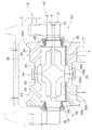
- FIG. 1 shows a longitudinal sectional view of the wheels of the crawler type traveling vehicle according to the first embodiment of the present invention.
- the rolling wheel 1 is disposed on the non-contacting surface side of the crawler belt, and includes a shaft 2, a roller assembly 3a, and two bushings 4 as bearings.
- the shaft 2 has support portions 2a of small diameter at both ends, ie, inner and outer end portions, and two bearing mounting portions 2b having a diameter larger than that of the support portion 2a at the central portion where the roller assembly 3a is disposed. have.
- the “inside” is the side closer to the vehicle body frame 8, that is, the right side in FIG. 1
- the “outside” is the side away from the vehicle body frame 8, that is, the left side in FIG.
- the support portions 2 a are supported by the large bogies 7 via the small bogies 6 respectively.
- the large bogie 7 is fixed to the vehicle body frame 8. Therefore, the shaft 2 is supported with respect to the vehicle body frame 8.
- the shaft 2 is formed with an oil supply hole 9 communicating with the outer peripheral surface of the shaft 2 from one inner end toward the outer side.
- a recess is formed at the axial center of the shaft 2, that is, between the two bearing mounting portions 2b.
- the roller assembly 3a has an inner roller shell 12 disposed on the inner side near the vehicle body frame 8, an outer roller shell 13 disposed on the outer side of the inner roller shell 12, and a combination of the roller shells 12 and 13. And a coupling ring 14. Since the inner roller shell 12 and the outer roller shell 13 are formed in a plane symmetry centering on their connecting surfaces, only the inner roller shell 12 will be described in detail here.
- the inner roller shell 12 is formed in a tubular shape, and has an inner coupling portion 15 and an inner tread portion 16 from the outer side on the left side in FIG. 1 toward the inner side.
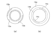
- the inner joint portion 15 has an inner annular groove 15a concentric with the rotation axis of the rotary wheel 1 at the outer peripheral portion of the outer end, as shown in an enlarged manner in FIG.
- On the outer peripheral portion of one (outside) side wall of the inner annular groove 15a there are provided two quarter circular projections 15b which project inward in the axial direction and which are concentric with the rotation axis of the rolling ring 1 .
- the two protrusions 15b are formed circumferentially in a range of 90 ° and arranged symmetrically with respect to the center. That is, between the circumferential direction of the two protrusions 15b, the non-formed portion of the protrusion 15b is present over a range of 90 °.
- the inner tread surface portion 16 has a diameter larger than that of the inner coupling portion 15, has a tread surface 16a on the outer circumferential surface with which the track link 17 contacts, and has a bearing mounting surface 16b on the inner circumferential surface.
- an annular flange 16c having a larger diameter than that of the other portions is formed.
- an inner boss 18 is formed further inside than the inner tread surface portion 16 of the inner roller shell 12.
- the inner boss 18 is formed on the inner peripheral portion of the inner end portion of the inner roller shell 12 and has an annular inner peripheral projecting portion 18a projecting to the inner peripheral side and an annular inner projecting portion projecting axially inward. And 18b.
- the floating seal 22 including the two O-rings 19a and 19b, the seal rings 20a and 20b, and the retaining ring 21 is provided on the projecting portions 18a and 18b.
- the inner roller shell 12 and the outer roller shell 13 are formed symmetrically, so that the outer roller shell 13 is provided with the “inner joint portion 15” and the “inner tread portion 16” of the inner roller shell 12.
- “Outer joint portion 25" corresponding to each of "inner annular groove 15a”, “protrusion 15b”, “tread surface 16a”, “bearing mounting surface 16b”, “annular flange 16c” and “inner boss 18", “outside A tread surface 26 ", an" outer annular groove 25a “, a” protrusion 25b “, a” footprint 26a “, a” bearing mounting surface 26b “, an” annular flange 26c “, and an” outer boss 28 "are formed.
- the outer boss 28 of the outer roller 13 is provided with a floating seal 22 including the same two O-rings and seal rings and a retaining ring.
- the coupling ring 14 is constituted by two semicircular split rings 14 (here, the “coupling ring” and the “split ring” are given the same reference numerals).
- the two split rings 14 have exactly the same configuration, and are C-shaped in cross section as shown enlarged in FIG. That is, the split ring 14 has a main body portion 14a axially extending in the outer peripheral portion, and a pair of leg portions 14b extending inward from both axial ends of the main body portion 14a. Then, two locking portions 14c that protrude inward (to the other leg side) are formed in each of the pair of legs 14b.
- the two locking portions 14c are formed so as to span an angle range smaller than 90 ° in the circumferential direction and to be symmetrical with respect to the center.
- the pair of leg portions 14b is fitted into the annular grooves 15a and 25a of the coupling portions 15 and 25, and the locking portion 14c straddles the protrusions 15b and 25b formed on the annular grooves 15a and 25a, respectively. It is locked on the inner circumference side of. 3A shows the cross section of the portion where the locking portion 14c is formed, and FIG. 3B shows the cross section of the portion where the locking portion 14c is not formed.
- the inner roller 12 and the outer roller 13 are integrally coupled by the two split rings 14 in a state in which the opposing end faces are butted.
- An oil reservoir 29 of lubricating oil is formed between the axially central portion and the shaft 2 at the inner peripheral portions of the two split rings 14.
- the two bushings 4 are mounted on the bearing mounting surface 16 b of the inner roller shell 12 and the bearing mounting surface 26 b of the outer roller shell 13 respectively. Therefore, both roller shells 12 and 13 are rotatably supported on the shaft 2 by the two bushings 4. Further, between the end surfaces of the bearing mounting portion 2 b of the shaft 2 and the end surfaces of the corresponding roller shells 12 and 13, thrust washers 30 each receiving a thrust force are disposed.
- FIG. 4 shows the shapes of the inner roller shell 12 and the coupling ring 14 at the time of insertion as viewed from the inside in the axial direction (viewed from the arrow AA in FIG. 1).
- the locking portion 14c formed on the pair of legs 14b of the two split rings 14 is an annular groove 15a, It positions so that it may come to the part in which protrusion 15b, 25b is not formed among 25a. In this state, since the locking portion 14c does not collide with the protrusions 15b and 25b, the pair of leg portions 14b of the split ring 14 can be fitted into the annular grooves 15a and 25a, respectively.
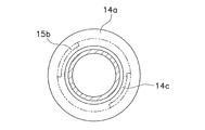
- the two split rings 14 fitted in the annular grooves 15a and 25a are rotated, and as shown in FIG. 5, the locking portions 14c of the two split rings 14 are projections of the annular grooves 15a and 25a. It is located in the part in which 15b and 25b are formed. As a result, as shown in FIG. 3, the locking portion 14c engages with the inner peripheral portions of the protrusions 15b and 25b.
- the inner roller shell 12 and the outer roller shell 13 are coupled. Thereafter, the floating seal 22 is attached to the bosses 18 and 28 of the roller shells 12 and 13, respectively.
- the roller shell is divided into only the inner roller shell 12 and the outer roller shell 13, and a member for supporting the floating seal 22 is integrated with the roller shell. For this reason, it is not necessary to form a screw hole for fixing a support member to a roller shell in a roller shell, and while being able to reduce a number of parts, manufacture and an assembly become easy.
- the shape and number of the annular groove and the protrusion formed in each of the roller shells 12 and 13 and the locking portion of the coupling ring 14 are not limited to the above embodiment.
- the coupling ring 14 may be provided with three or more locking portions.
- an inclined surface having an inclination in the circumferential direction is provided on one or both of the protrusion and the locking portion so that when the coupling ring (split ring) is rotated and assembled, it is firmly fixed according to the rotation. Also good.
- the two split rings may be coupled by pins as shown in FIG.
- locking notches 32a are formed on the inner circumferential side of one split ring 32 at one of the two split rings 32.
- a through hole 32b is formed through the notch 32a.
- locking notches 33a are formed on the outer peripheral sides of both ends, and through holes 33b penetrating the locking notches 33a in the radial direction are formed at the ends of both ends. ing.
- the pin 34 is inserted through both through holes 32b and 33b.
- the split rings 32, 33 can be rigidly fixed by the pins 34. For this reason, the operation
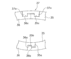
- first locking grooves 35a, 36a and locking projections 35b, 36b are formed at one end of each of the two split rings 35, 36.
- the respective locking projections 35b and 36b are locked to the first locking grooves 35a and 36a of the other ring.
- second locking grooves 35c and 36c are formed at the other ends of the split rings 35 and 36, respectively.
- the pair of leg portions 37a and 37a of the coupling member 37 is press-fitted into the locking second grooves 35c and 36c.
- the split rings 35 and 36 can be firmly fixed by the coupling member 37. For this reason, the operation
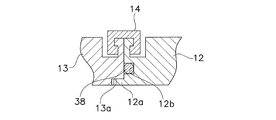
- FIG. 8 shows still another example.
- a convex portion 12 a is formed on the inner peripheral end of the outer end of the inner roller shell 12, and the inside of the inner end of the outer roller shell 13 is formed.
- a recess 13a is formed at the circumferential end.
- the convex portion 12 a is fitted into the concave portion 13 a, and the inner roller shell 12 is joined to the outer roller shell 13.
- the inner circumference of the joint portion is formed so as not to cause a step.
- an annular groove 12b for sealing is formed on the outer end surface of the inner roller shell 12, and an O-ring 38 as a sealing member is provided in the annular groove 12b.
- accurate positioning of the two roller shells 12 and 13 can be performed by joining the convex portion and the concave portion as described above. Further, since the O-ring 38 is provided on the mating surface of the two roller shells 12 and 13, leakage of lubricating oil inside can be further suppressed.
- FIG. 9 shows a roller 40 according to a second embodiment of the present invention.
- the roller 40 according to the second embodiment differs from the first embodiment in the inner roller shell, the outer roller shell, and the coupling ring constituting the roller assembly, but the other configuration is the same as that of the first embodiment.
- the other configuration is the same as that of the first embodiment.
- only parts different from the first embodiment will be described.
- the roller assembly 3b includes an inner roller shell 42 disposed on the inner side close to the vehicle body frame, an outer roller shell 43 disposed on the outer side of the inner roller shell 42, and both roller shells. And a coupling ring 44 for coupling 42, 43.
- the inner roller shell 42 is formed in a tubular shape, and includes an inner coupling portion 45 and an inner tread portion 46 from the outer side toward the inner side.
- the inner coupling portion 45 has an annular protrusion 47 projecting radially outward on the outer peripheral portion of the outer end.
- the outer peripheral surface 47 a of the projection 47 is formed in a tapered shape in which the radial direction becomes larger as it gets away from the outer roller shell 43, that is, as it goes inward.
- the axial inner end surface of the protrusion 47 is a locking surface 47 b.
- the inner tread surface portion 46 has a diameter larger than that of the inner coupling portion 45, and includes a tread surface 46a, a bearing mounting surface 46b, and an annular flange 46c as in the first embodiment. Furthermore, an inner boss 48 similar to that of the first embodiment is formed, and the floating seal 22 is provided on the inner boss 48.
- the outer roller shell 43 is formed in plane symmetry about the inner roller shell 42 and the connecting surface of the both, and thus the outer roller shell 43 is similarly formed with the outer joint portion 55, the outer tread portion 56, the projection 57, An outer peripheral surface 57a, a locking surface 57b, a tread surface 56a, a bearing mounting surface 56b, an annular flange 56c, and an outer boss 58 are formed.
- the outer boss 58 of the outer roller shell 43 is provided with a floating seal 22.
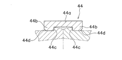
- the coupling ring 44 is an annular member having a predetermined length (width) in the axial direction, and as shown in an enlarged manner in FIG. 11, the main body portion 44 a axially extending in the outer peripheral portion and the axis of the main body portion 44 a And a pair of legs 44b extending inward from both directions. And, the inner side (the other leg side) of the pair of leg portions 44 b is a locking surface 44 c that locks with the locking surfaces 47 b and 57 b of the roller shells 42 and 43. A chamfered portion 44d is formed on the inner peripheral portion of the outer surface (surface opposite to the locking surface 44c) of the pair of leg portions 44b.
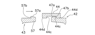
- the inner roller shell 42 and the outer roller shell 43 are coupled by the coupling ring 44.
- the coupling ring 44 is locked to the projection 57 of the outer roller 43 in the same procedure.
- the coupling ring 44 is engaged across the projections 47, 57, and the inner roller shell 42 and the outer roller shell 43 are coupled.
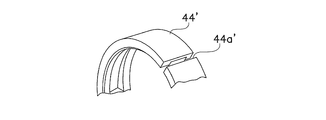
- a slit 44a ' may be formed in the coupling ring 44' along the axial direction, and the coupling ring 44 'may be a C-shaped snap ring.
- the coupling ring 44 ' when the coupling ring 44 'is engaged with the protrusions 47 and 57 of the roller shells 42 and 43, the coupling ring 44' can be easily expanded, and the assembling operation can be facilitated.
- the shape of the slits is not limited to that shown in FIG. 13.
- a plurality of slits having a short axial length may be formed so as not to penetrate from the both sides in the axial direction to the other side.
- the coupling ring 44 is an O-shaped ring.
- FIG. 14 shows a longitudinal sectional view of the wheels of the crawler type traveling vehicle according to the third embodiment of the present invention.
- the rolling wheel 101 is disposed on the non-contacting surface side of the crawler belt, and includes a shaft 102, a roller assembly 103a, and two bushings 104 as bearings.
- the shaft 102 has support portions 102a of small diameter at both ends, that is, the inner end and the outer end, and in the portion where the roller assembly 103a is disposed, two bearing mounting portions 102b having a diameter larger than the support portion 102a.
- the support portions 102 a are supported by the large bogies 107 via the small bogies 106 respectively.
- the large bogie 107 is fixed to the vehicle body frame 108. Therefore, the shaft 102 is supported with respect to the vehicle body frame 108.
- the shaft 102 is formed with an oil supply hole 109 communicating with the outer peripheral surface of the shaft 102 from the inner end toward the outer side.
- a recess is formed in the axial center of the shaft 102, that is, between the two bearing mounting portions 102b.
- the roller assembly 103 a includes an inner roller shell 112 disposed on the inner side near the vehicle body frame 108 and an outer roller shell 113 disposed on the outer side of the inner roller shell 112.
- the inner roller shell 112 is formed in a tubular shape and has an inner locking portion 115 at the outer end on the left side in FIG. 14 and an inner tread portion 116 inside the inner locking portion 115. .
- the outer end of the inner locking portion 115 is coupled to the outer roller shell 113 by a bridging structure.
- the inner locking portion 115 in particular its outer end, has a reduced radial thickness compared to the other portions in order to facilitate elastic deformation. Further, as shown in an enlarged manner in FIG. 15, the inner locking portion 115 is formed with an annular locking projection 115a projecting radially inward from the tip of the outer end portion. A seal surface 115b is formed on the inner peripheral side of the locking projection 115a, and the inner surface is a locking surface 115c.
- the inner tread portion 116 has a diameter larger than that of the inner locking portion 115, has a tread surface 116a on the outer circumferential surface with which the track link 117 contacts, and has a bearing mounting surface 116b on the inner circumferential surface. Further, at the innermost portion of the inner tread portion 116, an annular flange 116c having a larger diameter than the other portions is formed.
- an inner boss 118 is formed further inward than the inner tread surface portion 116 of the inner roller shell 112.
- the inner boss 118 is formed on the inner peripheral portion of the inner end portion of the inner roller shell 112, and an annular inner peripheral protrusion 118a that protrudes to the inner peripheral side and an annular inner protrusion that protrudes axially inward And 118b.
- the protruding portions 118a and 118b are provided with a floating seal 122 including two O-rings 119a and 119b, seal rings 120a and 120b, and a retaining ring 121.
- the outer roller shell 113 is formed in a cylindrical shape like the inner roller shell 112, and has an outer locking portion 125 at an inner end portion and an outer tread surface portion 126 at the outer side of the outer locking portion 125. ing.
- the tip of the outer locking portion 125 is smaller in diameter than the outer diameter of the inner locking portion 115.
- the outer locking portion 125 is formed with an annular locking groove 125a corresponding to the locking projection 115a of the inner locking portion 115, as shown in an enlarged manner in FIG.
- the locking protrusion 115 a of the inner locking portion 115 straddles the protrusion of the tip of the outer locking portion 125 and fits in the locking groove 125 a. Thereby, the inner roller shell 112 and the outer roller shell 113 are locked.
- a sealing annular groove 125b is formed on the bottom surface of the locking groove 125a, and a sealing member 114 is disposed in the sealing annular groove 125b.
- the seal member 114 is in pressure contact with the seal surface 115 b of the locking projection 115 a.
- a side surface on the inner side (right side in FIG. 15) of the locking groove 125a is a locking surface 125c, and the locking surface 115c of the locking projection 115a is locked to the locking surface 125c.
- the outer peripheral surface 125d of the tip end portion of the locking groove 125a is formed in a tapered shape in which the diameter decreases from the outer side to the inner side.
- the outer tread portion 126 is formed to be symmetrical to the inner tread portion 116. Therefore, the outer tread portion 126 is formed by the "tread surface 116a”, the “bearing mounting surface 116b”, the “annular flange 116c”, and “the inner tread surface 116". It has “tread surface 126a”, “bearing mounting surface 126b”, “annular flange 126c” and “outer boss 128” corresponding to each of the inner bosses 118 ”.
- the outer boss 128 of the outer roller shell 113 is provided with a floating seal 122 including the same two O-rings and seal rings and a retaining ring.
- the inner roller shell 112 and the outer roller shell 113 are engaged with each other by the locking projections 115a formed in the locking portions 115, 125 at the respective tip portions, and the locking groove 125a. It is combined.
- An oil reservoir 129 of lubricating oil is formed between the axially central portion and the shaft 102 at the inner peripheral portion of each locking portion 115, 125.
- the two bushings 104 as bearings are respectively mounted on the bearing mounting surface 116 b of the inner roller shell 112 and the bearing mounting surface 126 b of the outer roller shell 113. Therefore, the two roller shells 112 and 113 are rotatably supported on the shaft 102 by the two bushings 104. Further, thrust washers 130 each receiving a thrust force are disposed between both end surfaces of the bearing mounting portion 102 b of the shaft 102 and the end surfaces of the corresponding roller shells 112 and 113.
- the locking projection 115 a of the inner roller shell 112 is elastically deformed when passing over the outer peripheral surface 125 d of the tip end portion of the outer roller shell 113.
- the inner locking portion 115 in which the locking projection 115a is formed is thinner than the other portions, it is easily elastically deformed.
- the tip outer peripheral surface 125d of the outer roller 113 is formed in a tapered shape, the locking projection 115a can easily get over the outer peripheral tapered surface 125d.
- the inner roller shell 112 and the outer roller shell 113 are coupled. Thereafter, the floating seal 122 is attached to the bosses 118 and 128 of the roller shells 112 and 113, respectively.
- roller shell Since the roller shell is divided into only the inner roller shell 112 and the outer roller shell 113, no member for supporting the floating seal 122 is required. For this reason, it is not necessary to form a screw hole for fixing a support member to a roller shell in a roller shell, and while being able to reduce a number of parts, manufacture and an assembly become easy.
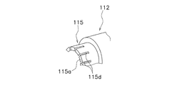
- a plurality of slits 115 d may be formed along the axial direction in the locking portion 115 of the inner roller shell 112 so as to further facilitate elastic deformation.
- the arrangement of the sealing annular groove and the sealing member is not limited to the above embodiment.
- the opposing end surfaces of the inner roller shell 112 and the outer roller shell 113 may be in contact with each other, and a sealing annular groove may be formed on this end surface to arrange the sealing member.
- FIG. 17 shows a wheel according to a fourth embodiment of the present invention.
- the roller according to the fourth embodiment differs from the third embodiment only in the locking portions of the inner and outer roller shells constituting the roller assembly, but the other configuration is the same as that of the third embodiment.
- the third embodiment differs from the third embodiment only in the locking portions of the inner and outer roller shells constituting the roller assembly, but the other configuration is the same as that of the third embodiment.
- only differences from the third embodiment will be described.
- an inner locking portion 135 is formed at the outer end of the inner roller shell 132.
- the locking portion 135 is formed to be thinner in the radial direction than other portions.
- an annular inner locking projection 135 a that protrudes radially outward is formed at the tip end of the locking portion 135.
- the inner surface 135b of the outer peripheral portion of the inner locking projection 135a is a tapered surface whose diameter decreases inward.
- the outer peripheral surface of the inner locking projection 135a is an inner fitting surface 135c, and the outer end surface is an axial positioning surface 135d.
- An outer locking portion 145 is formed at an inner end portion of the outer roller shell 133.
- the outer locking portion 145 is formed to have a smaller thickness in the radial direction than other portions.
- an outer locking projection 145 a that protrudes radially inward is formed at the tip of the outer locking portion 145.
- the outer surface 145b of the inner peripheral portion of the outer locking projection 145a is a tapered surface whose diameter increases toward the outer side (left side in FIG. 17).
- the tapered surface 145b of the outer locking projection 145a is formed to face the tapered surface 135b of the inner locking projection 135b so as to vertically overlap in the axial direction.
- the angle between the tapered surface 135b of the inner locking projection 135a and the tapered surface 145b of the outer locking projection 145 is set to 15 ° or less.
- a radially outer fitting surface 133c is formed on the inner peripheral portion of the outer roller shell 133 further outside (the left side in FIG. 17) than the outer locking portion 145.
- the radially outer fitting surface 133c is in contact with the inner fitting surface 135c of the inner locking protrusion 135a.
- an axial positioning surface 133d is formed to be in contact with the axial positioning surface 135d.
- the inner diameter of the inner end of the outer locking portion 145 of the outer roller shell 133 is larger than the outer diameter of the outer tip of the inner locking portion 135 of the inner roller shell 132. Then, the inner roller shell 132 is press-fit into the outer roller shell 133 until the positioning surfaces 133 d and 135 d abut, and the inner fitting surface 135 c and the outer fitting surface 133 c are engaged.
- a wedge ring 144 is provided between the tapered surface 135 b of the inner locking projection 135 a and the tapered surface 145 b of the outer locking projection 145.
- the wedge ring 144 is circular in cross section and has a notch at a part of its outer periphery. Therefore, the wedge ring 144 can expand its diameter.
- the wedge ring 144 having a circular cross-section is press-fit from the inside into the gap between the tapered surfaces 135b and 145b, and plastically deformed in the gap to make the cross-section into a wedge shape. As a result, the wedge ring 144 restrains the movement between the inner roller shell 132 and the outer roller shell 133 as a wedge and makes the locking between the two more strong.
- the inner locking protrusion 135a and the outer locking protrusion 145a are coupled via the wedge ring 144, whereby the inner roller shell 132 and the outer roller shell 133 are coupled.
- the inner locking portion 135 of the inner roller shell 132 assembled with the thrust washer 30, the bushing 104, and the wedge ring 144 is press-fit onto the tip inner periphery of the outer roller shell 133, and the inner locking protrusion 135a is fitted
- the surface 135 c is joined to the outer fitting surface 133 c of the outer roller shell 133, and the axial positioning surface 135 d of the inner locking projection 35 a is brought into contact with the axial positioning surface 133 d of the outer roller shell 133.
- the inner roller shell 132 and the outer roller shell 133 are positioned and fixed in the radial and axial directions.
- the wedge ring 144 mounted on the inner roller shell 132 is made of the tapered surface 135b of the inner locking protrusion 135a and the outer locking protrusion 145. It press-fits between the taper surface 145b.
- the jig 147 has a ring shape divided into two in the circumferential direction. In this way, the wedge ring 144 is fixed between the two tapered surfaces 135b and 145b, and the two roller shells 132 and 133 are more firmly connected.
- FIG. 18 shows a wheel according to a fifth embodiment of the present invention.
- the roller according to the fifth embodiment differs from the third embodiment only in the joint portion of the inner roller shell and the outer roller shell constituting the roller assembly, but the other configuration is the same as that of the third embodiment.
- the third embodiment differs from the third embodiment only in the joint portion of the inner roller shell and the outer roller shell constituting the roller assembly, but the other configuration is the same as that of the third embodiment.
- only differences from the third embodiment will be described.
- the outer end of the inner roller shell 152 is formed with an inner locking portion 155.
- the inner locking portion 155 is formed to have a smaller thickness in the radial direction than other portions.
- a female screw 155 b is formed on the inner peripheral surface of the tip end portion 155 a of the inner locking portion 155.
- the inner peripheral surface further inside of the female screw 155b is an inner fitting surface 155c, and the end surface of the outer side (left side in FIG. 18) is an axial positioning surface 155d.
- An outer locking portion 157 is formed at the inner end portion 157 a of the outer roller shell 153.
- the outer locking portion 157 is formed to have a smaller thickness in the radial direction than other portions.
- a male screw 157 b is formed on the outer peripheral portion of the outer locking portion 157.
- the male screw 157 b is screwed into the female screw 155 b of the inner locking portion 155.
- an outer fitting surface 157c is formed on the distal end side (inner side, that is, the right side of FIG. 18) of the portion where the male screw 157b is formed.
- the surface 157 d is formed.
- the outer fitting surface 157c and the axial positioning surface 157d respectively abut the inner fitting surface 155c and the axial positioning surface 155d of the inner roller shell 152, whereby both the roller shells 152 and 153 are in the radial and axial directions. Is positioned at
- a seal groove 157e is formed in the outer fitting surface 157c of the outer roller shell 157, and the seal member 158 is disposed in the seal groove 157e.
- each roller shell inward deformation of each roller shell inward can be suppressed, and partial contact between the bearing and the shaft disposed on the inner circumferential portion of the roller can be suppressed.
Landscapes
- Engineering & Computer Science (AREA)
- Chemical & Material Sciences (AREA)
- Combustion & Propulsion (AREA)
- Transportation (AREA)
- Mechanical Engineering (AREA)
- Rolling Contact Bearings (AREA)
- Rolls And Other Rotary Bodies (AREA)
Abstract
Description
図1に、本発明の第1実施形態による履帯式走行車両の転輪の縦断面図を示す。この転輪1は、履帯の非接地面側に配置されており、シャフト2と、ローラ組立体3aと、軸受としての2つのブシュ4と、を備えている。
シャフト2は、両端、すなわち内側端部及び外側端部に小径の支持部2aを有し、ローラ組立体3aが配置された中央部には支持部2aよりも大径の2つの軸受装着部2bを有している。ここで、「内側」とは、車体フレーム8に近い側、すなわち図1における右側であり、「外側」とは、車体フレーム8から離れる側、すなわち図1における左側である。そして、支持部2aがそれぞれ小ボギー6を介して大ボギー7に支持されている。また、大ボギー7は車体フレーム8に固定されている。したがって、シャフト2は車体フレーム8に対して支持されていることになる。また、このシャフト2には、内側の一端から外側に向かって、かつシャフト2の外周面に連通する給油孔9が形成されている。なお、シャフト2の軸方向中央部、すなわち2つの軸受装着部2bの間には凹部が形成されている。
ローラ組立体3aは、車体フレーム8に近い内側に配置された内側ローラシェル12と、この内側ローラシェル12の外側に配置された外側ローラシェル13と、両ローラシェル12,13を結合するための結合リング14と、を有している。内側ローラシェル12と外側ローラシェル13とはそれらの結合面を中心に面対称に形成されているので、ここでは内側ローラシェル12についてのみ詳細に説明する。
2つのブシュ4は、それぞれ、内側ローラシェル12の軸受装着面16bと、外側ローラシェル13の軸受装着面26bとに装着されている。したがって、この2つのブシュ4によって、両ローラシェル12,13はシャフト2に対して回転自在に支持されている。また、シャフト2の軸受装着部2bの両端面と、対応する各ローラシェル12,13の端面との間には、それぞれスラスト力を受けるスラストワッシャ30が配置されている。
シャフト2にローラ組立体3aを組み付ける場合は、まず、内側ローラシェル12及び外側ローラシェル13の内周部に、スラストワッシャ30を挿入するとともに、ブシュ4を組み付ける。次に、スラストワッシャ30及びブシュ4が組み付けられた内側ローラシェル12及び外側ローラシェル13を、それぞれシャフト2の支持部2aから挿入し、図1に示すように、両ローラシェル12,13の軸方向端面が当接するようにセットする。なお、ここで、両ローラシェル12,13に形成された環状溝15a,25aの突起15b,25bが円周方向において同じ位置になるように、それぞれのローラシェル12,13の角度を位置決めしておく必要がある。
(1)結合リング14が各ローラシェル12,13の外周部に形成された溝の突起を跨いで係止することによって2つのローラシェル12,13を結合しているので、各ローラシェル12,13が変形することがない。したがって、各ローラシェル12,13の内周部に配置されるブシュ4とシャフト2とが片当たりするのを防止できる。
(a)各ローラシェル12,13に形成された環状溝及び突起や、結合リング14の係止部の形状、個数については、前記実施形態に限定されない。例えば、結合リング14に3個以上の係止部を設けても良い。また、突起及び係止部の一方又は両方に、円周方向に傾斜を有する傾斜面を設け、結合リング(分割リング)を回転させて組み付ける際に、回転にしたがって強固に固定されるようにしても良い。
<構成>
図9に本発明の第2実施形態による転輪40を示す。この第2実施形態の転輪40は、ローラ組立体を構成する内側ローラシェル、外側ローラシェル、及び結合リングが第1実施形態と異なるが、他の構成は第1実施形態と同様である。ここでは、第1実施形態と異なる部分のみ説明する。
シャフト2にローラ組立体3bを組み付ける場合は、まず、第1実施形態と同様に、内側ローラシェル42及び外側ローラシェル43の内周部に、スラストワッシャ30を挿入するとともにブシュ4を組み付ける。次に、スラストワッシャ30及びブシュ4が組み付けられた内側ローラシェル42及び外側ローラシェル43のいずれか一方を、シャフト2の支持部2aから挿入する。ここでは、例えば内側ローラシェル42を先に挿入する。そして、内側ローラシェル42の結合部45の先端に、結合リング44を嵌合する。このとき、結合リング44の面取り部44dが内側ローラシェル42の先端に形成された突起47の外周テーパ面47aに乗り上げる。この状態からさらに結合リング44が押し込まれると、結合リング44及び内側ローラ42の先端部が互いに変形し、結合リング44の脚部44bが突起47を乗り越え、互いの係止面47b,44cが係止する。この状態を、図12に示している。
この第2実施形態では、第1実施形態とほぼ同様の特徴に加えて、突起47及び57と、結合リング44がすべて環状であるので、製造が容易になる。また、結合リング44が分割されていないので、結合リング自体の構成が簡単になる。
(a)突起及び結合リングの形状は前記実施形態に示した例に限定されない。例えば、図13に示すように、結合リング44’に軸方向に沿ってスリット44a’を形成して、結合リング44‘をC字形状のスナップリングとしてもよい。この場合は、結合リング44’と各ローラシェル42,43の突起47,57との係合時に、結合リング44’が拡がりやすくなり、組み付け作業が容易になる。
図14に、本発明の第3実施形態による履帯式走行車両の転輪の縦断面図を示す。この転輪101は、履帯の非接地面側に配置されており、シャフト102と、ローラ組立体103aと、軸受としての2つのブシュ104と、を備えている。
シャフト102は、両端、すなわち内側端部及び外側端部に小径の支持部102aを有し、ローラ組立体103aが配置された部分には支持部102aよりも大径の2つの軸受装着部102bを有している。そして、支持部102aがそれぞれ小ボギー106を介して大ボギー107に支持されている。また、大ボギー107は車体フレーム108に固定されている。したがって、シャフト102は車体フレーム108に対して支持されていることになる。また、このシャフト102には、内側の一端から外側に向かって、かつシャフト102の外周面に連通する給油孔109が形成されている。なお、シャフト102の軸方向中央部、すなわち2つの軸受装着部102bの間には凹部が形成されている。
ローラ組立体103aは、車体フレーム108に近い内側に配置された内側ローラシェル112と、この内側ローラシェル112の外側に配置された外側ローラシェル113と、を有している。
軸受としての2つのブシュ104はそれぞれ、内側ローラシェル112の軸受装着面116bと、外側ローラシェル113の軸受装着面126bとに装着されている。したがって、この2つのブシュ104によって、両ローラシェル112,113はシャフト102に対して回転自在に支持されている。また、シャフト102の軸受装着部102bの両端面と、対応する各ローラシェル112,113の端面との間には、それぞれスラスト力を受けるスラストワッシャ130が配置されている。
シャフト102にローラ組立体103aを組み付ける場合は、まず、内側ローラシェル112及び外側ローラシェル113の内周部に、スラストワッシャ130を挿入するとともに、ブシュ104を組み付ける。次に、スラストワッシャ130及びブシュ104が組み付けられた内側ローラシェル112及び外側ローラシェル113を、それぞれシャフト102の支持部102aから挿入する。そして、内側ローラシェル112の係止突起115aを外側ローラシェル113の先端部を跨いで係止溝125aに係止する。
(1)各ローラシェル112,113の係止部115,125に形成された係止突起115aと係止溝125aとを係止させることによって両ローラシェル112,113を結合しているので、従来の結合リングの圧入による結合に比較して、各ローラシェル112,113の変形が抑えられる。したがって、各ローラシェル112,113の内周部に配置されるブシュ104とシャフト102とが片当たりするのを防止できる。
(a)各ローラシェル112,113に形成された係止突起及び係止溝は、それぞれ前記実施形態と逆側に形成されていても良い。
<構成>
図17に本発明の第4実施形態による転輪を示す。この第4実施形態の転輪は、ローラ組立体を構成する内側ローラシェル、外側ローラシェルの係止部のみが第3実施形態と異なるが、他の構成は第3実施形態と同様である。ここでは、第3実施形態と異なる部分のみ説明する。
シャフト102にローラ組立体103bを組み付ける場合は、まず、第3実施形態と同様に、内側ローラシェル132及び外側ローラシェル133の内周部に、スラストワッシャ130を挿入するとともに、ブシュ104を組み付ける。また、内側ローラシェル132の結合部135の外周に、楔リング144を挿入しておく。
(a)内側ローラシェルと外側ローラシェルの結合部の具体的構成は前記実施形態に限定されない。例えば、各ローラシェルの結合部の構成を、前記実施形態と逆にしてもよい。
図18に本発明の第5実施形態による転輪を示す。この第5実施形態の転輪は、ローラ組立体を構成する内側ローラシェル、外側ローラシェルの結合部のみが第3実施形態と異なるが、他の構成は第3実施形態と同様である。ここでは、第3実施形態と異なる部分のみ説明する。
2,102 シャフト
3a,3b,103a ローラ組立体
4,104 ブシュ
8,108 車体フレーム
12,32,42,112,132,152 内側ローラシェル
13,33,43,113,133,153 外側ローラシェル
14,44 結合リング
14b,44b 1対の脚部
14c 係止部
47,57 突起
15,25,45,55 結合部
15a,25a 環状溝
15b,25b 突起
16,26,46,56 踏面部
16a,26a,116a,126a 踏面
44a’ スリット
Claims (19)
- 履帯の非接地面側に配置され、車体フレームに支持される履帯式走行車両の転輪であって、
前記車体フレームに支持されるシャフトと、
前記シャフトの外周に配置されたローラ組立体と、
前記ローラ組立体を前記シャフトに回転自在に支持する軸受と、
を備え、
前記ローラ組立体は、
前記車体フレームに近い側に配置される筒状の内側ローラシェルと、
前記内側ローラシェルに跨嵌構造により結合して前記内側ローラの外側に配置される筒状の外側ローラシェルと、
を有する、
履帯式走行車両の転輪。 - 前記跨嵌構造は、
前記内側ローラシェルの外側端の外周部に形成された内側係合部と、
前記外側ローラシェルの内側端の外周部に形成された外側係合部と、
前記内側ローラシェルの内側係合部と前記外側ローラシェルの外側係合部とを跨いで係合されて前記内側ローラシェルと外側ローラシェルを結合するための結合リングと、有する
請求項1に記載の履帯式走行車両の転輪。 - 前記内側ローラシェル及び前記外側ローラシェルの各係合部は、軸方向に突出する突起を円周方向の一部にのみ有する環状溝を有し、
前記結合リングは、複数の分割リングを含み、前記複数の分割リングのそれぞれは前記両ローラシェルの環状溝に嵌合可能な1対の脚部を有し、前記1対の脚部の一部には、前記突起に係止可能な係止部が形成されている、
請求項2に記載の履帯式走行車両の転輪。 - 前記複数の分割リングは、それぞれ半円形を有する2つの半割リングである、請求項3に記載の履帯式走行車両の転輪。
- 前記2つの半割リングのそれぞれは、一端部に形成され互いに係止可能な係止部と、他端部に軸方向に沿って形成された溝と、を有し、
前記結合リングは、前記溝に圧入されて前記2つの半割リングを固定する固定部材をさらに有している、
請求項4に記載の履帯式走行車両の転輪。 - 前記2つの半割リングのそれぞれは、両端部に径方向に貫通する貫通孔を有し、
前記結合リングは前記貫通孔を貫通して前記2つの半割リングを固定する2つのピンをさらに有する、
請求項4の記載の履帯式走行車両の転輪。 - 前記内側ローラシェル及び前記外側ローラシェルの各係合部は、径方向外方に突出する突起を有し、
前記結合リングは、前記両ローラシェルの突起に係合可能な1対の脚部を内周部に有する環状の部材である、
請求項2に記載の履帯式走行車両の転輪。 - 前記両ローラシェルの突起は、他方のローラシェルから離れるに従って外径が大きくなるテーパ状に形成されている、請求項7に記載の履帯式走行車両の転輪。
- 前記両ローラシェルの突起は前記両ローラシェルの全周に連続して形成されている、請求項8に記載の履帯式走行車両の転輪。
- 前記結合リングは弾性変形を容易にするために軸方向に少なくとも1つのスリットが形成されている、請求項7に記載の履帯式走行車両の転輪。
- 前記両ローラシェルの突起が形成された端部は径方向内側に弾性変形が可能である、請求項7に記載の履帯式走行車両の転輪。
- 前記跨嵌構造は、
前記内側ローラシェルの外側端部に形成された内側係止部と、
前記外側ローラシェルの内側端部に形成された外側係止部と、
を有し、
前記内側及び外側ローラシェルの係止部の一方が他方を跨いで係止して前記内側ローラシェルと前記外側ローラシェルとを結合する構造である
請求項1に記載の履帯式走行車両の転輪。 - 前記両ローラシェルの係止部の少なくとも一方は、径方向内方に突出する係止突起を有し、
前記両ローラシェルの係止部の少なくとも他方は、前記係止突起が係止する係止溝を有する、
請求項12に記載の履帯式走行車両の転輪。 - 前記内側ローラシェルの内側係止部及び前記外側ローラシェルの外側係止部の少なくとも一方は、他の部分に比較して径方向の厚みが薄く形成されている、請求項13に記載の履帯式走行車両の転輪。
- 前記係止溝が形成されたローラシェルの先端部外周面は、前記係止溝から先端にいくにしたがって径が小さくなるテーパ状に形成されている、請求項14に記載の履帯式走行車両の転輪。
- 前記係止部の少なくとも一方には、軸方向に沿って延びる複数のスリットが形成されている、請求項15に記載の履帯式走行車両の転輪。
- 前記係止溝の底面にはシール部材用の環状溝が形成されており、
前記環状溝に設けられたシール部材をさらに備え、
前記係止突起の内周面は前記シール部材を圧接している、
請求項13に記載の履帯式走行車両の転輪。 - 前記両ローラシェルの係止部は、径方向において互いに対向する傾斜面を有しており、
前記2つの傾斜面の間に挿入され、一部に切欠きを有して拡径可能な楔リングをさらに備え、
前記両ローラシェルの係止部は前記楔リングを介して係止している、
請求項12に記載の履帯式走行車両の転輪。 - 前記両ローラシェルの係止部の一方の外周面には雄ネジが形成されており、
前記両ローラシェルの係止部の他方には前記雄ネジが螺合する雌ネジが形成されている、
請求項1に記載の履帯式走行車両の転輪。
Priority Applications (2)
| Application Number | Priority Date | Filing Date | Title |
|---|---|---|---|
| US13/320,096 US20120056473A1 (en) | 2009-06-01 | 2010-05-31 | Roller wheel for track-type travelling vehicle |
| CN2010800209553A CN102421660B (zh) | 2009-06-01 | 2010-05-31 | 履带式行驶车辆的转轮 |
Applications Claiming Priority (2)
| Application Number | Priority Date | Filing Date | Title |
|---|---|---|---|
| JP2009-131815 | 2009-06-01 | ||
| JP2009131815A JP2010274872A (ja) | 2009-06-01 | 2009-06-01 | 履帯式走行車両の転輪 |
Publications (1)
| Publication Number | Publication Date |
|---|---|
| WO2010140558A1 true WO2010140558A1 (ja) | 2010-12-09 |
Family
ID=43297692
Family Applications (1)
| Application Number | Title | Priority Date | Filing Date |
|---|---|---|---|
| PCT/JP2010/059174 Ceased WO2010140558A1 (ja) | 2009-06-01 | 2010-05-31 | 履帯式走行車両の転輪 |
Country Status (4)
| Country | Link |
|---|---|
| US (1) | US20120056473A1 (ja) |
| JP (1) | JP2010274872A (ja) |
| CN (1) | CN102421660B (ja) |
| WO (1) | WO2010140558A1 (ja) |
Cited By (1)
| Publication number | Priority date | Publication date | Assignee | Title |
|---|---|---|---|---|
| JP2014139663A (ja) * | 2012-12-17 | 2014-07-31 | Ricoh Imaging Co Ltd | 鏡筒 |
Families Citing this family (24)
| Publication number | Priority date | Publication date | Assignee | Title |
|---|---|---|---|---|
| KR101146092B1 (ko) | 2009-12-11 | 2012-05-15 | 한국카모플라스트(주) | 충격흡수 홈을 구성한 고무 크로라 |
| CA2744630C (en) | 2010-06-30 | 2018-10-09 | Camoplast Solideal Inc. | Wheel of a track assembly of a tracked vehicle |
| US9067631B1 (en) | 2010-12-14 | 2015-06-30 | Camoplast Solideal Inc. | Endless track for traction of a vehicle |
| US9334001B2 (en) | 2010-12-14 | 2016-05-10 | Camso Inc. | Drive sprocket, drive lug configuration and track drive arrangement for an endless track vehicle |
| US8985250B1 (en) | 2010-12-14 | 2015-03-24 | Camoplast Solideal Inc. | Track drive mode management system and methods |
| JP5382664B2 (ja) * | 2011-01-28 | 2014-01-08 | 株式会社小松製作所 | 履帯式走行車両の下転輪 |
| JP5602967B1 (ja) * | 2014-03-05 | 2014-10-08 | 株式会社小松製作所 | 装軌式作業車両のためのローラ装置およびローラシェル |
| JP2015214292A (ja) * | 2014-05-13 | 2015-12-03 | 太平洋精機ホールディング株式会社 | 履帯式走行車両の転輪 |
| US11167810B2 (en) | 2015-03-04 | 2021-11-09 | Camso Inc. | Track system for traction of a vehicle |
| KR101836931B1 (ko) | 2015-03-31 | 2018-04-19 | 주식회사 진성티이씨 | 무한궤도 차량의 트랙 어셈블리 |
| WO2017000068A1 (en) | 2015-06-29 | 2017-01-05 | Camso Inc. | Systems and methods for monitoring a track system for traction of a vehicle |
| GB2541423B (en) * | 2015-08-19 | 2021-05-05 | Mahle Int Gmbh | Sliding element comprising at least one coupling element |
| CN107323547B (zh) * | 2017-07-06 | 2023-05-09 | 福建泉海工贸投资集团有限公司 | 拼接式引导轮 |
| EP3652049B1 (en) | 2017-07-11 | 2023-05-03 | Soucy International Inc. | Track system for a towed vehicle |
| CN107745754B (zh) * | 2017-11-09 | 2023-08-01 | 江苏徐工工程机械研究院有限公司 | 高可靠性导向轮结构及挖掘机 |
| CA3085012A1 (en) | 2017-12-08 | 2018-12-07 | Camso Inc. | Systems and methods for monitoring off-road vehicles |
| US11046376B2 (en) * | 2018-06-15 | 2021-06-29 | Flsmidth A/S | Undercarriage assembly for a rope shovel |
| WO2020041899A1 (en) | 2018-08-30 | 2020-03-05 | Camso Inc. | Systems and methods for monitoring vehicles with tires |
| WO2020041897A1 (en) | 2018-08-30 | 2020-03-05 | Camso Inc. | Systems and methods for monitoring tracked vehicles |
| US11667340B2 (en) * | 2020-03-06 | 2023-06-06 | Caterpillar Inc. | Screw profile mud-packing preventing |
| JP7007694B1 (ja) * | 2020-09-29 | 2022-01-25 | 矢崎化工株式会社 | クローラユニットとそれを使用した悪路用運搬台車 |
| US12049265B2 (en) * | 2020-12-21 | 2024-07-30 | Caterpillar Inc. | Roller assembly for ground-engaging track system |
| US11987302B2 (en) * | 2021-01-21 | 2024-05-21 | Caterpillar Inc. | Rim for a track roller |
| US11999420B2 (en) * | 2021-03-26 | 2024-06-04 | Caterpillar Inc. | Track roller for undercarriage system having inverted seal, and roller rim for same |
Citations (4)
| Publication number | Priority date | Publication date | Assignee | Title |
|---|---|---|---|---|
| JPH0527487U (ja) * | 1991-09-25 | 1993-04-09 | 株式会社クボタ | 切管用係止リング |
| JP2001271977A (ja) * | 2000-03-27 | 2001-10-05 | Toyo Tire & Rubber Co Ltd | 管の接続構造及び可とう継手 |
| JP2004149111A (ja) * | 2002-10-07 | 2004-05-27 | Komatsu Ltd | 履帯式走行車両の転輪 |
| JP2007170176A (ja) * | 2007-03-15 | 2007-07-05 | Jfe Steel Kk | 鋼管の継手構造 |
Family Cites Families (15)
| Publication number | Priority date | Publication date | Assignee | Title |
|---|---|---|---|---|
| JPS5215844B2 (ja) * | 1971-02-24 | 1977-05-04 | ||
| US3773393A (en) * | 1972-09-20 | 1973-11-20 | Gen Motors Corp | Track roller assembly |
| DE7638967U1 (de) * | 1976-12-13 | 1977-04-21 | Skf Kugellagerfabriken Gmbh, 8720 Schweinfurt | Abgedichtete Laufwerksrolle |
| US4152031A (en) * | 1977-08-25 | 1979-05-01 | Caterpillar Tractor Co. | Track roller with oil filter |
| US4209205A (en) * | 1977-12-20 | 1980-06-24 | Caterpillar Tractor Co. | Inspection of track assemblies |
| US4141598A (en) * | 1978-02-21 | 1979-02-27 | Caterpillar Tractor Co. | Track roller assembly |
| US5302012A (en) * | 1993-01-14 | 1994-04-12 | Caterpillar, Inc. | Composite tread ring for track roller |
| DE9306775U1 (de) * | 1993-05-05 | 1993-12-02 | Lippische Felgen- und Schutzblechfabrik Hans Kerkhoff GmbH & Co KG, 32107 Bad Salzuflen | Radfelge |
| DE19528837A1 (de) * | 1995-08-05 | 1997-02-06 | Intertractor Ag | Laufrolle für Raupenketten |
| US6074023A (en) * | 1996-07-24 | 2000-06-13 | Hitachi Construction Machinery Co., Ltd. | Guide roller assembly for crawler type vehicles and method for forming guide roller |
| DE60010340T2 (de) * | 2000-03-03 | 2005-05-12 | Split S.R.L., Zola Predosa | Achs-/rolleneinheit für raupenfahrzeuge |
| US20020153773A1 (en) * | 2001-04-24 | 2002-10-24 | Jinsung T.E.C. Co., Ltd. | Track roller |
| CN100586777C (zh) * | 2002-10-07 | 2010-02-03 | 株式会社小松制作所 | 履带式行驶车辆的转轮 |
| JP4288564B2 (ja) * | 2003-03-14 | 2009-07-01 | 株式会社小松製作所 | 転輪用シャフト |
| US7374257B2 (en) * | 2005-02-11 | 2008-05-20 | Caterpillar Inc. | Machine track roller assembly |
-
2009
- 2009-06-01 JP JP2009131815A patent/JP2010274872A/ja active Pending
-
2010
- 2010-05-31 CN CN2010800209553A patent/CN102421660B/zh not_active Expired - Fee Related
- 2010-05-31 WO PCT/JP2010/059174 patent/WO2010140558A1/ja not_active Ceased
- 2010-05-31 US US13/320,096 patent/US20120056473A1/en not_active Abandoned
Patent Citations (4)
| Publication number | Priority date | Publication date | Assignee | Title |
|---|---|---|---|---|
| JPH0527487U (ja) * | 1991-09-25 | 1993-04-09 | 株式会社クボタ | 切管用係止リング |
| JP2001271977A (ja) * | 2000-03-27 | 2001-10-05 | Toyo Tire & Rubber Co Ltd | 管の接続構造及び可とう継手 |
| JP2004149111A (ja) * | 2002-10-07 | 2004-05-27 | Komatsu Ltd | 履帯式走行車両の転輪 |
| JP2007170176A (ja) * | 2007-03-15 | 2007-07-05 | Jfe Steel Kk | 鋼管の継手構造 |
Cited By (1)
| Publication number | Priority date | Publication date | Assignee | Title |
|---|---|---|---|---|
| JP2014139663A (ja) * | 2012-12-17 | 2014-07-31 | Ricoh Imaging Co Ltd | 鏡筒 |
Also Published As
| Publication number | Publication date |
|---|---|
| CN102421660A (zh) | 2012-04-18 |
| US20120056473A1 (en) | 2012-03-08 |
| JP2010274872A (ja) | 2010-12-09 |
| CN102421660B (zh) | 2013-10-16 |
Similar Documents
| Publication | Publication Date | Title |
|---|---|---|
| JP2010274872A (ja) | 履帯式走行車両の転輪 | |
| US7374257B2 (en) | Machine track roller assembly | |
| US8231184B2 (en) | Crawler track roller with internal spherical spacers | |
| KR101479050B1 (ko) | 캐터필러 부시 및 캐터필러 링크 장치 | |
| US10589808B2 (en) | Splined idler for scallop resistance | |
| US20170175813A1 (en) | Cylindrical roller bearing | |
| JP7378461B2 (ja) | 保持リングを備えるフランジ型マスタ軌道ピン | |
| KR101699710B1 (ko) | 휠 베어링 체결 구조 및 체결 방법 | |
| JPH01126420A (ja) | 多列玉軸受又はころ軸受又は複合玉ころ軸受 | |
| JP2011527973A (ja) | 自己潤滑式転輪アセンブリおよび同アセンブリを使用する機械 | |
| WO2014003149A1 (ja) | 取付板付き転がり軸受ユニットおよびその製造方法 | |
| KR20220082894A (ko) | 트랙 차량용 환형 지지 구조체 | |
| JP2004276696A (ja) | 転輪用シャフト | |
| US10046816B2 (en) | Cartridge assembly with a flexible thrust ring assembly for a track chain | |
| KR101383268B1 (ko) | 휠 베어링 조립체 | |
| JP2015128924A (ja) | 軸受モジュール | |
| US8157453B2 (en) | Bearing device for wheel | |
| KR101431097B1 (ko) | 휠 베어링 조립체 | |
| JP2016114124A (ja) | 転がり軸受装置 | |
| AU2022268868A1 (en) | Undercarriage track roller having asymmetric shell with oil grooves and roller shaft for same | |
| CN205854313U (zh) | 锁紧组件、枢轴及履带支重轮框架 | |
| JP2010269697A (ja) | 履帯式走行車両の転輪 | |
| KR102939147B1 (ko) | 볼 베어링용 분할형 케이지 | |
| CN215166007U (zh) | 用于拉紧轴的轴座和拉紧轴组件 | |
| JP2009236223A (ja) | 転がり軸受 |
Legal Events
| Date | Code | Title | Description |
|---|---|---|---|
| WWE | Wipo information: entry into national phase |
Ref document number: 201080020955.3 Country of ref document: CN |
|
| 121 | Ep: the epo has been informed by wipo that ep was designated in this application |
Ref document number: 10783341 Country of ref document: EP Kind code of ref document: A1 |
|
| WWE | Wipo information: entry into national phase |
Ref document number: 13320096 Country of ref document: US |
|
| NENP | Non-entry into the national phase |
Ref country code: DE |
|
| 122 | Ep: pct application non-entry in european phase |
Ref document number: 10783341 Country of ref document: EP Kind code of ref document: A1 |