WO2010140513A1 - ステレオ画像撮影装置及びその方法 - Google Patents
ステレオ画像撮影装置及びその方法 Download PDFInfo
- Publication number
- WO2010140513A1 WO2010140513A1 PCT/JP2010/058885 JP2010058885W WO2010140513A1 WO 2010140513 A1 WO2010140513 A1 WO 2010140513A1 JP 2010058885 W JP2010058885 W JP 2010058885W WO 2010140513 A1 WO2010140513 A1 WO 2010140513A1
- Authority
- WO
- WIPO (PCT)
- Prior art keywords
- image
- previous
- unit
- live
- overlapping area
- Prior art date
- Legal status (The legal status is an assumption and is not a legal conclusion. Google has not performed a legal analysis and makes no representation as to the accuracy of the status listed.)
- Ceased
Links
Images


Classifications
-
- H—ELECTRICITY
- H04—ELECTRIC COMMUNICATION TECHNIQUE
- H04N—PICTORIAL COMMUNICATION, e.g. TELEVISION
- H04N5/00—Details of television systems
- H04N5/76—Television signal recording
- H04N5/91—Television signal processing therefor
- H04N5/92—Transformation of the television signal for recording, e.g. modulation, frequency changing; Inverse transformation for playback
-
- G—PHYSICS
- G03—PHOTOGRAPHY; CINEMATOGRAPHY; ANALOGOUS TECHNIQUES USING WAVES OTHER THAN OPTICAL WAVES; ELECTROGRAPHY; HOLOGRAPHY
- G03B—APPARATUS OR ARRANGEMENTS FOR TAKING PHOTOGRAPHS OR FOR PROJECTING OR VIEWING THEM; APPARATUS OR ARRANGEMENTS EMPLOYING ANALOGOUS TECHNIQUES USING WAVES OTHER THAN OPTICAL WAVES; ACCESSORIES THEREFOR
- G03B35/00—Stereoscopic photography
- G03B35/02—Stereoscopic photography by sequential recording
-
- H—ELECTRICITY
- H04—ELECTRIC COMMUNICATION TECHNIQUE
- H04N—PICTORIAL COMMUNICATION, e.g. TELEVISION
- H04N23/00—Cameras or camera modules comprising electronic image sensors; Control thereof
- H04N23/60—Control of cameras or camera modules
- H04N23/63—Control of cameras or camera modules by using electronic viewfinders
-
- G—PHYSICS
- G06—COMPUTING OR CALCULATING; COUNTING
- G06T—IMAGE DATA PROCESSING OR GENERATION, IN GENERAL
- G06T3/00—Geometric image transformations in the plane of the image
-
- G—PHYSICS
- G11—INFORMATION STORAGE
- G11B—INFORMATION STORAGE BASED ON RELATIVE MOVEMENT BETWEEN RECORD CARRIER AND TRANSDUCER
- G11B27/00—Editing; Indexing; Addressing; Timing or synchronising; Monitoring; Measuring tape travel
-
- H—ELECTRICITY
- H04—ELECTRIC COMMUNICATION TECHNIQUE
- H04N—PICTORIAL COMMUNICATION, e.g. TELEVISION
- H04N13/00—Stereoscopic video systems; Multi-view video systems; Details thereof
- H04N13/20—Image signal generators
- H04N13/204—Image signal generators using stereoscopic image cameras
- H04N13/207—Image signal generators using stereoscopic image cameras using a single 2D image sensor
- H04N13/221—Image signal generators using stereoscopic image cameras using a single 2D image sensor using the relative movement between cameras and objects
-
- H—ELECTRICITY
- H04—ELECTRIC COMMUNICATION TECHNIQUE
- H04N—PICTORIAL COMMUNICATION, e.g. TELEVISION
- H04N13/00—Stereoscopic video systems; Multi-view video systems; Details thereof
- H04N13/20—Image signal generators
- H04N13/296—Synchronisation thereof; Control thereof
-
- H—ELECTRICITY
- H04—ELECTRIC COMMUNICATION TECHNIQUE
- H04N—PICTORIAL COMMUNICATION, e.g. TELEVISION
- H04N5/00—Details of television systems
- H04N5/76—Television signal recording
- H04N5/765—Interface circuits between an apparatus for recording and another apparatus
- H04N5/77—Interface circuits between an apparatus for recording and another apparatus between a recording apparatus and a television camera
Definitions
- the present invention relates to a stereo image photographing apparatus and a method thereof. More specifically, the present invention relates to a stereo image capturing apparatus and method for appropriately determining an overlapping area between a previously captured image and a current captured image.
- JP 2007-183256 A (FIGS. 1 to 11, paragraphs 0021 to 0065)
- the present invention has been made in view of the above problems, and a stereo image photographing apparatus capable of appropriately determining an overlapping region between a previous photographed image and a current photographed image when photographing while moving using a single camera. And an object thereof.
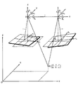
- the stereo image capturing apparatus 1 overlaps the measurement object 2 with a single camera.
- a capturing unit that acquires the live image 25 of the measurement object 2 as needed with the movement of the camera, captures the measurement object 2 in a timely manner, and acquires a captured image that is a still image.
- the overlap area setting section 6 that sets the overlap area 23 with the live image 25 in the previous captured image 21 that is the captured image previously captured by the capturing section 3, and the previously captured image 21 and the live image 25 are overlapped.
- the overlapping area 23 set by the area setting unit 6 is displayed in an overlapping manner, the previous captured image 21 is displayed by extending from the overlapping area 23 in the direction opposite to the moving direction of the imaging unit 3, and the live image 25 is displayed from the overlapping area 23.
- a display unit 4 for displaying extend on the same side as the moving direction of the shadow 3.
- the stereo image photographing device refers to a photographing device that normally includes a pair of cameras and shoots a measurement object in an overlapping manner.
- the measurement object is overlapped.
- An imaging apparatus that sequentially captures images while performing the above.
- the live image 25 is an image acquired at the current position using a camera such as a video camera or a digital camera that can acquire and display images continuously, and dynamically changes as the camera moves.
- the live image 25 is overwritten in the temporary memory and transferred to the display unit 4.
- the live image 25 is sampled at an appropriate frame interval or time interval, stored in a memory for a predetermined period (temporarily), and used for image processing.
- the live image 25 at the current position is acquired as the current captured image 22 which is a captured image scheduled to be captured this time by the shutter operation. Therefore, in the display area 26 of the display unit 4, if the image of the overlapping area (live image overlapping area 25 a) in the live image 25 is approximately coincident with the image of the overlapping area 23 in the previous captured image 21, it is planned.
- the captured image 22 can be obtained this time.
- the overlap area 23 is set by setting the overlap ratio and the overlap direction for the previously captured image 21.
- the overlap ratio is set, for example, in% and can be set to an arbitrary value.
- the overlapping direction is typically set to one of left side, right side, upper side, and lower side.
- the overlapping ratio is set as a horizontal ratio and a vertical ratio.
- the overlap typically overlaps a semi-transparent image, but the transparency (density) of the semi-transparent image can be arbitrarily selected. For example, when three images are overlapped, if the density is set low, the overlapping portion of the three images becomes dark and easy to distinguish. For example, if the moving direction of the photographing unit 3 is on the right side, displaying the previous captured image 21 from the overlapping region 23 and the overlapping region 23 and displaying the previous captured image 21 extending from the overlapping region 23 to the opposite side to the moving direction of the photographing unit 3.
- the live image 25 is displayed on the left side and extended from the overlap region 23 to the same side as the moving direction of the photographing unit 3 to display the live image 25 on the overlap region 23 and the right side thereof.
- the term “approximately coincidence” means that it is sufficient that they coincide within the margin even if they do not coincide completely. This is because if the overlapping area is set with a margin, there is no problem if the overlapping areas match. For example, since the overlap ratio may be set to a little over 50% for three-dimensional measurement, if the overlap ratio is set to 60%, a deviation of ⁇ 5% is not a problem, and a tolerance of slightly less than ⁇ 10% is acceptable.
- the live image 25 can be displayed in the display area 26 of the display unit 4 so as to overlap the overlap region 23 of the previous captured image 21, and the appropriate shooting position for the camera to capture the current captured image 22. You can visually determine whether or not Thereby, in the case of shooting while moving using a single camera, it is possible to provide the stereo image shooting device 1 in which the overlapping area 23 between the previous shot image 21 and the current shot image 22 can be appropriately determined.
- the stereo image photographing device 1 displays the photographed image and the live image 25 with a frame in the first aspect, for example, as shown in FIG. .
- the captured image includes, in addition to the previous captured image 21, a previously captured image, an initial captured image, and the like. If comprised like this aspect, the range of a picked-up image and the live image 25 can be displayed clearly.
- the overlapping area setting unit 6 sets the overlapping area 23 to 50 to 70% of the previous captured image 21.
- the overlapping ratio is preferably, for example, 10% or more when creating a continuous image such as a panoramic image or an all-around image, but for measuring the three-dimensional shape of the measuring object 2, for example, 50 to 70%. Is preferable, and 55 to 65% is more preferable.
- it can be set to any value depending on the situation. If comprised like this aspect, all the imaging
- the stereo image photographing device 1 of the fourth aspect of the present invention is the measurement object 2 in the previous photographed image 21 and the live image 25 in any of the first to third aspects, for example, as shown in FIG.
- the overlapping region setting unit 6 sets the overlapping region 23 in the previous captured image 21 on the same side as the moving direction determined by the camera moving direction determining unit 8. If comprised in this way, the direction of an overlap area can be set correctly, without adding equipment, such as a sensor.
- the stereo image photographing device 1B has a GPS or an inertial sensor as shown in FIG. 19 in any of the first to third aspects, and moves the photographing unit 3.
- a moving direction detecting unit 15 that detects a direction is provided, and the overlapping region setting unit 6 sets the overlapping region 23 in the previous captured image 21 on the same side as the moving direction detected by the moving direction detecting unit 15. If comprised in this way, the direction of an overlap area
- the stereo image photographing device 1C can input in advance the moving direction of the photographing unit 3 in any one of the first to third aspects, for example, as shown in FIG.
- the overlapping area setting unit 6 sets the overlapping area 23 in the previous captured image 21 on the same side as the input moving direction. If comprised in this way, an overlapping area
- the stereo image photographing device 1A is the measurement object 2 in the previous photographed image 21 and the live image 25 as shown in FIG. 10, for example, in any of the first to sixth aspects.
- the display unit 4 includes a displacement correction image forming unit 13 that performs a displacement correction process on the previously captured image 21 and the live image 25 using the position and tilt of the camera to form a displacement correction image.
- the displacement correction image formed by the displacement correction image forming unit 13 is displayed.
- the deviation correction processing is performed on the subject so that the stereo image geometry is established with respect to the measurement object 2 using the photographing position and inclination of the camera obtained by the orientation.
- This is a process of correcting the image so that the epipolar line coincides with the left and right horizontal lines in parallel (see FIG. 12). Therefore, distortions such as magnification and inclination of the left and right images are corrected, and the positions of the magnification and height are the same.
- the previously captured image 21 and the live image 25 can be displayed in a superimposed manner in a stereoscopically viewable manner, and an image that is almost the same can be obtained when overlapping. .
- the stereo image photographing device 1 is a photographed image obtained by the overlapping region setting unit 6 previously photographed as shown in FIG. 8, for example, in any of the first to seventh aspects.
- the overlap area set in the previous shot image 27 is the previous image overlap area 27a
- the overlap area set in the previous shot image 21 is the previous image overlap area 21a
- the display unit 4 rotates the previous shot image 27 and the last shot image 21
- the image overlap area 27a is displayed in an overlapping manner
- the previous image captured image 27 is displayed extending from the image overlap area 27a to the side opposite to the moving direction of the image capturing unit 3
- the previous image image 21 is displayed from the image overlap area 27a before the image capture area.
- the previous captured image 21 and the live image 25 are displayed in a superimposed manner in the previous image overlap area 21 a, and the previous captured image 21 is displayed as the previous image.
- Displays extend to the side opposite to the moving direction of the imaging unit 3 from the multiple area 21a, and displays the extend on the same side as the moving direction of the imaging unit 3 live images 25 from the previous image overlap region 21a.
- the previous image overlap area 27a has already been set in the previous shot image 27 by the overlap area setting unit 6 at the time of previous shooting.
- the moving direction of the photographing unit 3 refers to the moving direction from the photographing position of the previous photographed image 21 to the photographing position of the live image 25, and typically the previous photographed image from the photographing position of the last photographed image 21 and the last photographed image 27. This corresponds to the moving direction to the photographing position 21. If they do not match, it is sufficient to shoot after correcting the movement direction of the photographer. For example, if the moving direction of the photographing unit 3 is on the right side, displaying the previous captured image 21 from the previous image overlapping area 21a to the opposite side to the moving direction of the photographing unit 3 is displayed as the previous captured image 21.
- the live image 25 is displayed on the overlap area 21a and the left side thereof, and the live image 25 is extended from the previous image overlap area 21a to the same side as the moving direction of the photographing unit 3 and displayed. And on the right side.
- the previously captured image 27, the previous captured image 21, and the live image 25 can be displayed in an overlapped manner on the display area 26, and the tie region 29 that is tripled can be confirmed.
- “overlapping” means that they do not have to be completely matched, but need only be matched within the margin. For example, if the image overlap area 27a is set with a margin for overlapping with the live image 25, the image overlap area 27a is not problematic as long as it matches within the margin.
- the overlap ratio is set to 20%, a deviation of ⁇ 5% is not a problem, and a tolerance of ⁇ 20% is acceptable. Even if a deviation occurs within the margin, it can be sufficiently recovered by intentionally shifting the image in the reverse direction in the next image capturing. Of course, it is preferable to match as much as possible in order to maintain the uniformity of the image processing, for example, within ⁇ 3%.
- the overlap area setting unit 6 includes the image overlap area 27a and the previous image overlap area 21a.
- the image overlap area 27a and the previous image overlap area 21a are set the previous time so as to overlap at least partially. If comprised in this way, by this, all the imaging regions of the measuring object 2 can be imaged, and the three-dimensional shape of the measuring object 2 can be measured.
- the stereo image photographing device 1A measures the previous photographed image 21 and the live image 25 as shown in FIGS. 10 and 16, for example.
- the feature point extraction unit 7 that extracts the feature points of the target object 2 and the feature point extraction unit 7 extracts the feature points of the measurement target object 2 extracted from the live image 25 and the first shot image 28 that is a first shot image.
- the corresponding point search unit 8a that performs stereo matching with the feature point of the measurement object 2 extracted from the image, and when an overlapping region is found between the live image 25 and the first captured image 28 by stereo matching,
- the area setting unit 6 sets the overlapping area in the first shot image 28 as the one-round image overlapping area 28c, and the display unit 4 sets the first shot image 28 and the live image 25 to the one-round image overlapping area 28c. Cascade to display. With this configuration, it can be seen that when the first shot image 28 is displayed, shooting is completed in the current or next shooting.
- the stereo image photographing device 1A in any one of the first to ninth aspects, measures the previous photographed image 21 and the live image 25 as shown in FIGS. 10 and 16, for example.
- the feature point extraction unit 7 that extracts the feature points of the target object 2, the live image 25 extracted by the feature point extraction unit 7, and the feature points of the measurement target object 2 in the first captured image 28 that is the first captured image
- the three-dimensional coordinate calculation unit 14 for obtaining the three-dimensional coordinates of the respective photographing positions from the screen positions of the live image 25 and the first-captured image 28 based on the three-dimensional coordinates of the photographing position in the first-captured image 28.
- the overlapping area setting 6 sets the overlapping area as the one-round image overlapping area 28c, and the display unit 4 And 28 and live images 25 displayed superimposed in round image overlap region 28c.
- the stereo image photographing device 1B of the twelfth aspect of the present invention in the fifth aspect, as shown in FIG. 19, for example, a live image 25 detected by a GPS or an inertial sensor and a photographed image photographed for the first time.
- the overlap area setting unit 6 overlaps the first shot image 28 with the overlap area.
- the area 28c is set, and the display unit 4 displays the first shot image 28 and the live image 25 so as to overlap each other in the round image overlap area 28c.
- “turning once” means moving to the same direction and reaching a position where shooting from all directions planned by the current shooting is completed. For example, when shooting from 12 directions is scheduled, this means that the 12th shooting position has been reached.
- the stereo image photographing device 1C can input the fact that the photographer has made one round as shown in FIG. 21, for example, as shown in FIG. Is input, the overlap region setting unit 6 sets the one-round image overlap region 28c in the first shot image 28 which is the first shot image, and the display unit 4 The live image 25 and the live image 25 are displayed so as to overlap each other in the round image overlap area 28c. With this configuration, it can be seen that when the first shot image 28 is displayed, shooting is completed in the current or next shooting.
- the stereo image capturing device 1A in any one of the first to ninth aspects, measures the previous captured image 21 and the live image 25 as shown in FIGS. 10 and 18, for example.
- a feature point extraction unit 7 that extracts feature points of the object 2
- a location unit 12 that obtains the position and inclination of the camera of the photographing unit 3 using the feature points extracted by the feature point extraction unit 7, and a location unit 12
- a three-dimensional coordinate calculation unit 14 for obtaining the three-dimensional coordinates of the feature points using the obtained camera position and tilt, and the overlapping area setting unit 6 includes the feature points obtained by the three-dimensional coordinate calculation unit 14.
- the overlap area between the previous captured image 21 and the live image 25 is set as the previous overlap area 21c in the previous captured image 21 and the live overlap area 25c in the live image 25, and the display unit 4 Last time
- the shadow image 21 and the live image 25 are both included in the display area 26 so that the same part of the measurement object 2 substantially overlaps in the previous overlap region 21c and the live overlap region 25c, and both are framed. To display.
- the previous overlap region 21c and the live overlap region 25c may be represented by a rectangle that connects and overlaps the outermost feature points that overlap. If comprised like this aspect, the image of the measuring object 2 in the live side overlapping area 25c can be displayed more accurately. Further, by comparing the positions of the overlapping area 23 and the live side overlapping area 25c, it can be determined whether or not to shoot. When the deviation is large, the live side overlapping area 25c may be moved closer to the overlapping area 23, and both areas may be photographed together. Further, according to the position of the live-side overlap area 25c, that is, according to the shooting direction, the previous shot image 21, the live image 25, and the positions of these frames are changed and displayed.
- a stereo image capturing method for sequentially capturing an object to be measured 2 with a single camera as shown in FIG.
- the overlapping area 23 set in the setting process (S130 and S180) is displayed in an overlapping manner, and the previous captured image 21 is opposite to the moving direction of the imaging unit 3 from the overlapping area 23.
- Extension to display, and a display step (S190) of displaying extend on the same side as the moving direction of the imaging unit 3 live images 25 from the overlap region 23.
- the live image 25 can be displayed in the display area 26 of the display unit 4 so as to be superimposed on the overlapping area 23 of the previous captured image 21, so that the camera can capture images suitable for capturing the current scheduled image 22. You can visually determine whether or not you are in position.
- a stereo image shooting method in which an overlapping region 23 between the previous shot image 21 and the current shot image 22 can be appropriately determined.
- a stereo image photographing apparatus and method capable of appropriately determining an overlapping area between a previous photographed image and a current photographed image when photographing while moving using a single camera.
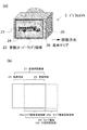
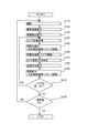
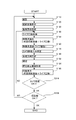
- FIG. 1 is a block diagram illustrating a configuration example of a stereo image capturing device according to Embodiment 1.
- FIG. It is a figure for demonstrating the duplication area
- FIG. 5 is a diagram illustrating an example of a processing flow of image capturing according to the first embodiment.
- FIG. 10 is a diagram illustrating an example of a processing flow of image capturing according to a second embodiment.
- FIG. 10 is a block diagram illustrating a configuration example of a stereo image capturing apparatus according to a third embodiment. It is a figure for demonstrating mutual orientation. It is a figure for demonstrating a deviation correction image. It is a figure for demonstrating the magnification of a picked-up image and a display image. It is a figure for demonstrating the stereo method.
- FIG. 10 is a diagram illustrating an example of a processing flow of image capturing according to a third embodiment.
- FIG. 10 is a diagram illustrating an example of a processing flow of image capturing according to a fourth embodiment. It is a figure which shows the example displayed by changing the position of the last picked-up image, a live image, and these frames according to the imaging direction.
- FIG. 10 is a block diagram illustrating a configuration example of a stereo image photographing device according to Embodiment 6.
- FIG. 10 is a diagram illustrating an example of a processing flow of image capturing according to a sixth embodiment.
- FIG. 10 is a block diagram illustrating a configuration example of a stereo image capturing device according to Embodiment 7.
- FIG. 10 is a diagram illustrating an example of a processing flow of image capturing according to a seventh embodiment.
- the first embodiment is an example in which the previously captured image and the live image are overlapped and displayed in the display area of the display unit.
- the camera moving direction determining unit obtains the moving direction of the photographing unit, and the overlapping region setting unit determines the camera moving direction.
- An example in which an overlapping area is set on the same side as the movement direction determined by the section will be described.
- FIG. 1 is a block diagram showing a configuration example of a stereo image photographing apparatus 1 according to the first embodiment of the present invention.
- the stereo image photographing device 1 obtains a live image of the measurement object 2 as needed as the camera moves, captures the measurement object 2 in a timely manner, and obtains a still image as a still image.
- the display unit 4 for displaying the image processed image
- the input unit 9 for the operator to input data and instructions
- the storage unit 5 for storing the captured image, the live image, the image processed image, etc.
- An overlapping area setting unit 6 that sets an overlapping area with a live image on a previous captured image that is a captured image, a feature point extracting unit 7 that extracts feature points from the captured image and the live image, and a feature point extracting unit 7 From the screen position of the extracted feature point in the previous captured image and the live image, the camera movement direction determination unit 8 that determines the moving direction of the photographing unit 3, the stereo image photographing device 1, and the control unit 10 that controls each of the components.
- the overlapping area setting unit 6, the feature point extraction unit 7, the camera movement direction determination unit 8, and the control unit 10 are configured in a personal computer (PC) 16. Each of these units may be configured as a processing unit in the digital camera, but in the present embodiment, it is configured in the PC 16.
- the stereo image photographing apparatus 1 is suitable for obtaining a whole image of the measurement object 2 by connecting a large number of photographed images, for example, photographing the entire circumference of the measurement object 2.
- it is suitable for obtaining a photographed image for performing three-dimensional measurement by performing duplicate photographing over the entire measurement object 2.
- the photographing unit 3 is composed of a single camera such as a video camera or a digital camera. The photographer uses a single camera as the photographing unit 3 to sequentially capture images while providing an overlapping region while moving around the measurement object 2, for example.
- the display unit 4 includes a display such as a liquid crystal display, for example. At least the previously captured image 21 and the live image 25 of the measurement object 2 are displayed in the display area 26 so as to overlap each other.
- the display area 26 can display a range wider than the shooting range, and the range shot by the shutter operation is the range displayed as the live image 25.
- the display unit 4 may display an image that has been subjected to image processing, such as a previously captured image and a displacement corrected image.
- a speaker is provided for voice display.
- the input unit 9 includes, for example, a mouse and a keyboard, and is used for an operator to input data and instructions.
- the storage unit 5 is composed of a hard disk, for example, and is used as a database.
- a captured image storage unit 51 that stores the captured image
- a live image storage unit 52 that stores the live image 25
- a processed image storage unit 53 that stores an image-processed image such as a displacement corrected image
- a position coordinate storage unit 54 that stores the position coordinates of the photographing position is provided.
- a photographed image is usually stored in an external memory by a shutter operation, but if there is an internal memory, it is stored there.
- a captured image is stored in an internal memory by a shutter operation.
- live images taken by the video camera or digital camera while the photographer moves are always overwritten in the temporary memory of the live image storage unit 52 and transferred to the display unit 4.
- image processing is required to determine the moving direction from the live image. Therefore, the live image is sampled at an appropriate frame interval or time interval, and stored in the memory of the live image storage unit 52 for a predetermined period (temporarily). The predetermined period may be a time sufficient for determining the moving direction, for example. Therefore, the live image storage unit 52 has a temporary memory and a memory for storing the sampled live image.
- the internal memory of the camera may be used as the storage unit 5, it is preferable to use the hard disk of the PC 16 because it is suitable for various processes at high speed.
- a camera using an external memory stores a captured image directly in the storage unit 5, and a camera using an internal memory transfers the captured image to the storage unit 5.
- the overlapping area setting unit 6 sets an overlapping area 23 with the live image 25 in the previous captured image 21 that is the captured image previously captured by the capturing unit 3.
- This overlapping area 23 is also an area in which the previous captured image 21 and the current captured image 22 which is a captured image scheduled to be captured this time are overlapped and captured.
- the display area 26 of the display unit 4 if shooting is performed when the image of the live image overlapping area 25 a that is an overlapping area in the live image 25 substantially coincides with the image of the overlapping area 23 in the previous captured image 21, the scheduled current shooting is performed. An image 22 can be obtained.
- the overlapping area setting unit 6 sets the overlapping ratio and the overlapping direction for the overlapping area 23.
- the overlapping area 23 is set on the same side as the moving direction determined by the camera moving direction determination unit 8.
- the overlapping region 23 is set and displayed on the right side of the previous photographed image 21.
- the display area 26 can display a range wider than the shooting range, and the range shot by the shutter operation is the range displayed as the live image 25. Therefore, if shooting is performed when the image of the live image overlapping area 25a, which is the overlapping area in the live image 25, does not match the image of the overlapping area 23 in the previous captured image 21, the captured image deviated from the scheduled current captured image 22 is obtained. can get.
- the term “approximately coincidence” means that it is sufficient that they coincide within the margin even if they do not coincide completely. This is because if the overlapping area is set with a margin, there is no problem if the overlapping areas match. For example, since the overlap ratio may be set to a little over 50% for three-dimensional measurement, if the overlap ratio is set to 60%, a deviation of ⁇ 5% is not a problem, and a tolerance of slightly less than ⁇ 10% is acceptable. Even if a deviation occurs within the margin, it can be sufficiently recovered by intentionally shifting the image in the reverse direction in the next image capturing. Of course, it is preferable to match as much as possible in order to maintain the uniformity of image processing, for example, within ⁇ 3%.
- the overlap ratio can be arbitrarily set according to the situation. For example, when it is desired to finely observe the measurement object 2 or to finely track the feature point, it is set to 90%. When the measurement object 2 may be coarsely observed, the feature point is coarsely tracked. For example, it may be set to 55%.
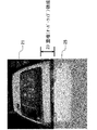
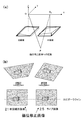
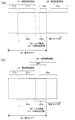
- FIG. 2 is a diagram for explaining an overlapping area in the display area.
- FIG. 2A shows the overlapping state in the display area 26, and FIG. A car as the measurement object 2 is displayed in a display area 26 (a region surrounded by a thick solid line frame on the outside in FIG. 2A) of the display unit 4 attached to the digital camera as the photographing unit 3.
- the inside solid line frame is the previous photographed image 21, which is arranged on the left side of the display area 26, here near the left end, and the broken line frame is the live image 25, on the right side of the display area 26, here near the right end. Has been placed. That is, this is a case where the moving direction of the photographing unit 3 is the right direction.
- the display area 26 there is a portion within the inner solid line frame and within the broken line frame, which is an overlapping region (overlap region) 23 between the previous captured image 21 and the live image 25.
- This overlapping area 23 is also an area in which the previously captured image 21 and the current captured image 22 which is the captured image scheduled to be captured this time are overlapped and captured.
- the overlap ratio is about 60%.
- the previously captured image 21 and the live image 25 are displayed so as to overlap each other in the overlapping area 23, and the previous captured image 21 is displayed extending from the overlapping area 23 to the left (opposite to the moving direction of the capturing unit 3). Is displayed extending from the overlapping area 23 to the right side (the same side as the moving direction of the photographing unit 3).
- the extended portion is the extended region 24, and in the live image 25, the portion in the overlapping region 23 is the live image overlapping region 25a, and the extended portion is the live image extended region. 25b. If shooting is performed when the image of the measurement object 2 in the live image overlap area 25a substantially coincides with the image of the measurement object 2 in the overlap area 23, the scheduled current captured image 22 can be obtained.
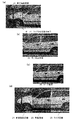
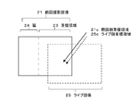
- FIG. 3 shows an example (part 1) in which a live image is displayed in duplicate on the previously captured image.
- the measurement object 2 is an automobile.
- FIG. 3A shows the previously captured image 21
- FIG. 3B shows the current captured image 22 scheduled to be captured this time
- FIG. 3C shows the live image 25
- FIG. 3D shows the previously captured image 21. Shows an image in which the live image 25 is overlapped.
- FIG. 2 for image codes.
- the overlap region 23 is set to the right half of the broken line in the previous photographed image 21, and the left half is the extension region 24.
- the left half is a portion that overlaps the overlapping region 23 set in the previous captured image 21.
- the left half is the live image overlap area 25a
- the right half is the live image extension area 25b.
- the previous captured image is arranged on the left 2/3 slightly
- the live image is disposed on the right 2/3
- the previously captured image 21 and the live image 25 are displayed in the overlap area 23 of the center 1/3 slightly.
- Duplicate display In the figure, the live image 25 is surrounded by a dotted line and is displayed slightly shifted upward from the previously captured image 21. If the position and angle of the camera are adjusted and shooting is performed when the same portion of the measurement object 2 in the previous captured image 21 and the live image 25 substantially overlaps in the overlapping region 23, the scheduled current captured image 22 can be obtained. it can.
- FIG. 4 shows an example (part 2) in which a live image is displayed in duplicate on the previously captured image.
- the measurement object 2 is an automobile.
- FIG. 3 shows an example in which the previous captured image 21 and the live image 25 are displayed side by side, but FIG. 4 shows an example in which the previous captured image 21 and the live image 25 are displayed side by side.
- the live image 25 is shown on the lower side in a direction surrounded by a dotted line.
- the range of the center arrow is the overlapping region 23.
- the live image 25 is displayed slightly shifted to the right side.
- the captured image 22 can be obtained this time.
- the feature point extraction unit 7 extracts feature points from the captured image.
- the feature points include, for example, the center position, the center of gravity position, the corner position of the measurement object 2, a position having a different characteristic from others, and a sign affixed or projected on the measurement object 2.
- a feature extraction operator is used for feature point extraction.
- a Moravec operator is used for feature point extraction.
- the MORAVEC operator has long been used as a general-purpose feature extractor.
- the MORAVEC operator uses, for example, a 3 ⁇ 3 pixel around a certain target pixel as a mask, and sets the minimum value of the density difference (direction density difference) when the mask moves one pixel in each of the four directions around the target pixel.
- the feature value It is characterized by simple and high-speed processing and relatively easy hardware. In order to perform high-speed processing, a memory several times as large as an image is required.
- the Harris operator has been described here, other operators, for example, the Harris operator and others, and anything that can detect feature points may be used.
- the camera movement direction determination unit 8 moves the photographing unit 3 from the screen position of the feature point extracted by the feature point extraction unit 7 in the previous captured image 21 and the live image 25 or from the change in the screen position between the live images 25. Find the direction. That is, using the previously captured image 21 and the live image 25 as a stereo image, the feature points of the previously captured image are associated with the feature points of the live image, and the movement vector of the feature point of the live image 25 with respect to the feature point of the previously captured image 21 is obtained. It can be obtained and averaged in the overlapping area, and the direction opposite to the average movement vector can be obtained as the moving direction of the photographing unit 3.
- Correspondence of feature points is performed by the corresponding point search unit 8a. It is also possible to track a feature point of a live image, obtain an average movement vector from changes in feature points between live images, and obtain a moving direction when movement in the same direction has continued a predetermined number of times (for example, three times or more). good. Note that the predetermined number of times may be one time, and tracking of feature points may be omitted.
- a live image is shot by operating the shutter at a position that is too far from the planned shooting position, it is preferable that the photographed image can be discarded by inputting a discard signal by the photographer. After that, it is preferable for the photographer to move back to the shooting position of the previous captured image in order to ensure the determination by the camera movement direction determination unit 8.
- FIG. 5 is a diagram showing an example of feature points and corresponding points in a stereo image.
- FIG. 5A shows feature points extracted from the left image
- FIG. 5B shows feature points extracted from the right image
- FIG. 5C shows associated feature points.
- the left image and the right image form a stereo pair, and are photographed at a position slightly shifted left and right.
- the positions of many points attached to the automobile as the measurement object 2 are the positions of the points extracted as feature points.
- Most of these feature points are associated by the corresponding point search, and are displayed in a three-dimensional coordinate space (here, a perspective view is used) in FIG.
- These feature points are assigned feature point numbers, and the three-dimensional position coordinates and the position coordinates in the left and right images are stored in the position coordinate storage unit 54.
- FIG. 6 is a diagram for explaining a corresponding point search for associating feature points between stereo images.
- Cross-correlation processing is used for the association.
- the template image of N 1 ⁇ N 1 pixel is moved on the search range (M 1 ⁇ N 1 +1) 2 in the larger input image of M 1 ⁇ M 1 pixel, and C
- the upper left position (a, b) of the template image that maximizes (a, b) is obtained, and it is considered that the template image has been searched.
- a template image of N 1 ⁇ N 1 pixel is set on the left image
- a search region of M 1 ⁇ M 1 pixel is set on the right image, and this operation is performed on each image. What is necessary is just to do about a position.
- the control unit 10 has a control program in the built-in memory, controls the stereo image capturing device 1 and each unit constituting the same, controls the flow of signals and data, and executes the function as the stereo image capturing device.
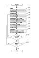
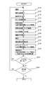
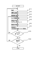
- FIG. 7 shows an example of a processing flow of image capturing according to the present embodiment.
- An example in which the previously captured image and the live image are displayed in the display area in an overlapping manner will be described.
- the measurement object 2 is imaged by the shutter operation of the imaging unit 3 (imaging process: S110).
- the captured image is stored in the captured image storage unit 51.
- the captured image is displayed in the display area 26 of the display unit 4 (captured image display step: S120), and the overlapped region setting unit 6 captures the previous captured image that was captured in the capturing step and displayed in the captured image display step.
- An overlap ratio is set in 21 (overlap ratio setting step: S130).
- the overlap area 23 is set for the overlap ratio and the overlap direction.
- the overlapping area setting process includes an overlapping ratio setting process (S130) and an overlapping direction setting process (S180) described later.
- the overlap ratio is set first, but the overlap direction is set temporarily.
- the overlapping area 23 in the previous captured image 21 displayed in the display area 26 in the captured image display step (S120). Is displayed surrounded by a frame.
- the photographer clicks a confirmation button on the display screen with a mouse for example, the overlap ratio is set, and the overlap direction is temporarily set.
- the overlapping direction is set in the subsequent overlapping direction setting step (S180).
- a live image is acquired (live image acquisition step: S140).
- the live image is always overwritten in the temporary memory of the live image storage unit 52 and transferred to the display unit 4.
- sampling is performed at an appropriate frame interval or time interval and stored in the live image storage unit 52 for a predetermined period (temporarily).
- a predetermined period temporary period (temporarily). For example, when the overlapping ratio is set to “60 (%)” and the overlapping direction is temporarily set to “right (side)”, 60% of the previous captured image 21 becomes the overlapping area 23 and is displayed in the display area 26.
- the previous captured image 21 is displayed extending from the overlapping area 23 to the left side (ie, the overlapping area and the left side thereof), and the live image is displayed extending from the overlapping area to the right side (ie, the overlapping area and its area). On the right).
- the temporary setting of the overlapping direction may be omitted, and the live image 25 may be displayed in the center of the display area 26 until the overlapping direction is finally set.
- feature points are extracted from the previous photographed image 21 and live image 25 (feature point extraction step: S150).
- the live image 25 for example, an image after a predetermined time (for example, 3 sec) has elapsed since the last captured image 21 was captured from images sampled at an appropriate frame interval or time interval, and feature points are extracted.
- the corresponding point search unit 8a associates the overlapping feature points.
- the camera movement direction determination unit 8 captures a direction opposite to the average movement vector from the average movement vector of the corresponding point of the live image 25 with respect to the feature point of the previously captured image 21 (the feature point associated with the corresponding point search unit 8a). It can be obtained as the moving direction of the part 3.
- feature points are tracked for the live image 25 (feature point tracking step: S160). For example, a live image after 6 sec and a live image after 9 sec are selected in addition to the live image after 3 sec since the last captured image 21 was captured. The corresponding point of the live image after 6 sec is searched for the feature point of the live image after 3 sec, and the average movement vector is obtained. Further, the corresponding point of the live image after 9 sec is searched for the feature point of the live image after 6 sec, and the average movement vector is obtained. In this way, the feature points of the live image can be tracked.
- the tracking time interval can be arbitrarily set according to the situation. For example, 1 sec is set when it is desired to track feature points finely, and 5 sec is set when the feature points may be tracked coarsely.
- the camera movement direction determination unit 8 moves the photographing unit 3 from the screen position of the feature point extracted by the feature point extraction unit 7 in the previous captured image 21 and the live image 25 or from the change in the screen position between live images.
- a direction is obtained (moving direction determination step: S170).
- a direction opposite to the direction of the average movement vector obtained from the previous photographed image 21 and live image 25 can be obtained as the movement direction of the photographing unit 3.
- the direction opposite to the direction of the average movement vector is set as the movement direction of the photographing unit 3. You may ask.
- the overlapping area setting unit 6 performs the main setting of the overlapping direction (overlapping direction setting step: S180).
- the overlapping area setting unit 6 sets an overlapping area 23 with the live image 25 in the previous captured image 21 on the same side as the movement direction determined by the camera movement direction determination unit 8. For example, when it is determined that the moving direction of the photographing unit 3 is the right direction, the overlapping region 23 is set on the right side of the previous photographed image 21.
- the display unit 4 displays the previously captured image 21 and the live image 25 in the display area 26 in an overlapping manner (display process: S190).
- the overlap area is set to “right (side)” and “60 (%)”
- 60% of the previous captured image becomes the overlap area 23
- the previous captured image 21 in the display area 26 is the overlap area 23.
- the live image 25 is displayed on the right side which is the same side as the moving direction of the photographing unit 3 from the overlapping area 23.
- the photographer monitors the overlapping state of the previously captured image 21 and the live image 25 in the display area 26, and determines whether or not the shooting position and the camera angle are appropriate (camera position determination step: S210). If an image is taken when the same portion of the measurement object 2 in the previous captured image 21 and the live image 25 substantially overlaps in the overlapping area 23, the scheduled current captured image 22 can be obtained. If there is a difference between the previously captured image 21 and the live image 25 in the overlapping area 23 (NO in S210), the shooting position and the camera angle are adjusted, and the live image acquisition process (S140) to the image display process (S190) are performed. repeat.
- the number of captured images has reached a predetermined number (photographing end determination step: S220).
- the scheduled number of shots is registered in the control unit 10 in advance, and the number of shots is counted for each shot, and the control unit 10 compares the counted number of shots with the registered scheduled number of shots.
- the shooting process (S110) to the camera position determination process (S210) are repeated.
- the counted number of shots ⁇ the scheduled number of shots (YES in S220)
- a stereo image shooting apparatus and method for appropriately determining an overlapping area between a previous shot image and a current shot image can provide.
- the previously captured image and the live image are displayed in the display area of the display unit in an overlapping manner.
- the previously captured image, the previously captured image and the live image are displayed in the display area of the display unit.
- images are displayed in duplicate will be described.
- the configuration of the stereo image photographing device 1 is the same as that of the first embodiment. Differences from the first embodiment will be mainly described.
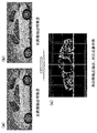
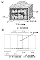
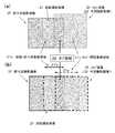
- FIG. 8 shows an example in which live images are displayed in duplicate on the previous and last captured images.
- 8A shows the display unit 4 of the digital camera 3
- FIG. 8B shows the camera display area 26 on a plane.
- a car as the measurement object 2 is displayed in the display area 26 of the display unit 4 of the digital camera 3 (a region surrounded by an outer solid line frame in FIG. 8A).
- the inner solid line frame is the image 27 taken two times before and is arranged on the left side of the display area 26, here, near the left end
- the one-dot chain line frame is the previous photographed image 21, arranged in the center of the display area 26, and broken line
- the inside of the frame is a live image 25, which is arranged on the right side of the display area 26, here near the right end.
- the inner solid line frame and the portion within the alternate long and short dash line frame form an overlapping area (overlap area) between the previous captured image 27 and the previous captured image 21, and the previous image repeated area 27 a set as the previous captured image 27. is there.
- the portion within the one-dot chain line frame and within the broken line frame is an overlapping region (overlap region) between the previous captured image 21 and the live image 25, and is the previous image overlapping region 21 a set to the previous captured image 21.
- the overlapping ratio of these overlapping areas is about 60%.
- the portion extending from the previous image overlap area 27a to the left side (opposite to the moving direction of the image capturing unit 3) of the previous image shot image 27 is the previous image extension area 27b and the left side of the previous image image 21 from the previous image overlap area 21a (shooting).
- the part extending in the direction opposite to the moving direction of the part 3) is the previous image extension area 21b
- the part overlapping the previous image overlap area 21a of the live image 25 is the live image overlap area 25a
- the part extending rightward from the live image overlap area 25a Is the live image extension area 25b.
- the portion inside the solid line frame and the broken line frame inside is a triple overlap region (overlap region) of the previously captured image 27, the previous captured image 21 and the live image 25, and is a tie region 29.
- the overlapping ratio of the tie area 29 is about 20%. In this way, by overlapping the live image 25 and the previous captured image 27, it is possible to overlap the entire imaging region of the measurement object 2, and to obtain the three-dimensional coordinates of the entire imaging region of the measurement object 2. If shooting is performed when the image of the live image overlapping area 25a in the live image 25 substantially matches the image of the previous image overlapping area 21a in the previous captured image 21, the scheduled current captured image 22 can be obtained.
- the planned current photographing image 22 can be obtained.
- substantially match means that it is only necessary to match within the margin even if they do not match completely.
- the image overlap area 27a is set with a margin for overlapping with the live image 25
- the image overlap area 27a is not problematic as long as it matches within the margin.
- the overlap ratio is set to 20%, there is no problem with a deviation of ⁇ 5%, and a little less than ⁇ 20% Is acceptable.
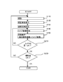
- FIG. 9 shows an example of a processing flow of image capturing according to the second embodiment.
- the previously captured image 27, the previously captured image 21 and the live image 25 are displayed in the display area 26 in an overlapping manner.
- the image display process (190) of the first embodiment see FIG. 7
- the previous captured image 21 and the live image 25 are displayed.
- the previously captured image 27 is displayed in the image display process (192).
- the difference is that the previously captured image 21 and the live image 25 are displayed. Therefore, the live image 25 can be viewed overlapping the previous captured image 27 and the previous captured image 21. In particular, it is possible to confirm the overlap in the tie area 29 and obtain a photographed image.
- a three-dimensional position measurement function is added to the first embodiment, and a displacement correction image can be created, the three-dimensional position coordinates of the feature point of the measurement object, and the shooting position of the camera can be measured.
- An example of correcting the magnification of an image displayed using an image will be described. Differences from the first embodiment will be mainly described.
- FIG. 10 is a block diagram illustrating a configuration example of a stereo image photographing device 1A according to the third embodiment of the present invention.
- a three-dimensional position measurement unit 11 is added to the configuration of the first embodiment (see FIG. 1).
- the three-dimensional position measurement unit 11 uses the feature points extracted by the feature point extraction unit 7 to determine the camera position and inclination of the photographing unit 3, and the camera position and inclination obtained by the orientation unit 12.
- It has a three-dimensional coordinate calculation unit 14 that calculates the three-dimensional position coordinates of the feature point of the object 2 and the shooting position.
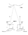
- a model image refers to a three-dimensional image obtained when a subject is reproduced from two or more photographed images. Forming relatively similar model images is called relative orientation. That is, the relative orientation determines the position and inclination of the projection center of each of the left and right cameras so that the two corresponding light beams of the captured image meet.
- FIG. 11 is a diagram for explaining relative orientation. Next, the details of the orientation calculation of each model image will be described. By this calculation, the positions of the left and right cameras (three-dimensional coordinates and three-axis tilt) are obtained. The parameters relating to the positions of these cameras are obtained by the following coplanar conditional expression.
- the origin of the model coordinate system is taken as the left projection center, and the line connecting the right projection centers is taken as the X axis.
- the base line length is taken as the unit length.
- the parameters to be obtained at this time are the rotation angle ⁇ 1 of the left camera, the rotation angle ⁇ 1 of the Y axis, the rotation angle ⁇ 2 of the right camera, the rotation angle ⁇ 2 of the Y axis, and the rotation of the X axis. the five of the rotation angle of the corner ⁇ 2. In this case, since the rotation angle ⁇ 1 of the X axis of the left camera is 0, it is not necessary to consider.
- unknown parameters are obtained by the following procedure.
- the position and tilt of the camera can be obtained. If the position of the camera is obtained by the relative orientation method, it is possible to obtain the three-dimensional coordinates on the object space point, that is, the three-dimensional coordinates of the feature points by the stereo method.
- a target can be arranged around the measurement object 2 and the coordinates of the photographing position can be obtained using the DLT method.
- the calculation is performed by the three-dimensional coordinate calculation unit 14.
- the DLT method approximates the relationship between the photographic coordinates and the three-dimensional coordinates (target point coordinates) of the subject using a cubic projective transformation equation.
- FIG. 12 is a diagram for explaining a deviation corrected image.
- FIG. 12A is a diagram for explaining the displacement correction image three-dimensionally
- FIG. 12B is a diagram for explaining the plan.
- the displacement correction process is performed by the displacement correction image forming unit 13.
- the deviation correction process is performed in parallel to the subject so that the stereo image geometry is established for the measurement object 2 using the shooting position and tilt of the camera obtained by the orientation. This is a process of correcting the image so that the epipolar line matches the left and right horizontal lines. Therefore, distortions such as magnification and inclination of the left and right images are corrected, and the positions of the magnification and height are the same.
- FIG. 12 is a diagram for explaining a deviation corrected image.
- FIG. 12A is a diagram for explaining the displacement correction image three-dimensionally
- FIG. 12B is a diagram for explaining the plan.
- the displacement correction process is performed by the displacement correction image forming unit 13.
- the deviation correction process is performed in parallel to the subject so that the stereo image
- the shooting positions of the camera 3 for shooting the left image and the right image of the stereo image are O 1 and O 2 , and the position of the measurement point of the measurement object 2 is P, respectively.
- the origin of the three-dimensional position coordinate and O 1, the three-dimensional coordinate axes X, Y, and Z axis. Since the shot images taken at the shooting positions O 1 and O 2 vary in the shooting distance and the camera angle, the magnification and inclination of the image are distorted as shown by the thin solid squares. These captured images are corrected to an image with the same magnification as viewed from the front of the camera, as shown by a thick solid square, by a deviation correction process.
- the magnification and the inclination are distorted in the previous captured image that is the left image and the live image that is the right image.
- the epipolar line is corrected by the displacement correction process so that the epipolar line coincides with the left and right horizontal lines for the previously captured image 21 that is the left image and the live image 25 that is the right image.
- the tilt is aligned.
- the model coordinates are (X1, Y1), the position coordinates in the captured image plane are (X C1 , Y C1 ), for the right image, the model coordinates are (X2, Y2), and the position coordinates in the captured image plane are (X C2 , Y C2 ), C1 and C2 are the focal lengths of the cameras in the captured images at the capturing positions O 1 and O 2 , m11 to m33 are the conversion parameters for the left image, and n11 to n33 are the conversion parameters for the right image. Then, the conversion expressions are expressed by (Expression 8) and (Expression 9). Thereby, the displacement correction process is performed.
- FIG. 13 is a diagram for explaining the magnification of the captured image and the display image.
- FIG. 13A is a diagram showing that the magnification of the last-time photographed image 27, the last-time photographed image 21, and the live image 25 is different.
- FIG. 13B is the display area 26, and the last-time photographed image 27, the last-time photographed image 21, and the live image. It is a figure which shows that the image 25 is displayed on the range of the same magnitude
- the last-time photographed image 27, the last-time photographed image 21, and the live image 25 are displayed in the same size range.
- the overlapping area 27o between the last-time captured image 27 and the previous captured image 21 and the overlapping area 21o between the previous captured image 21 and the live image 25 in FIG. 13A are shown in FIG.
- the image overlap area 27a and the previous image overlap area 21a are displayed two times before. Accordingly, the magnification of each image is different in each of the overlapping areas 21a and 27a, and the magnification of the three images is displayed differently in the tie area 29.
- the image is inclined in each of the overlapping regions 21 a and 27 a and the tie region 29. Therefore, if a deviation correction process is performed on the last-time photographed image 27, the previous photographed image 21, and the live image 25 to correct the deviation-corrected image, the images have the same magnification and are viewed from the front. Thereby, in the overlapping areas 21a and 27a and the tie area 29, the same part of the measuring object 2 in the two or three images can be displayed so as to be almost coincident with each other. Note that the reason why they do not completely match is that the positional relationship between the feature points changes somewhat depending on the viewing direction. As a result, the previous captured image 21 and the live image 25 can be matched well in the overlapping region 21a or the tie region 29, and the current captured image 22 can be captured more accurately.
- FIG. 14 is a diagram for explaining the stereo method.
- the three-dimensional position coordinates of each feature point of the measurement object 2 can be measured using the principle of the stereo method.
- the calculation of the three-dimensional position coordinates is performed by the three-dimensional coordinate calculation unit 14. Therefore, the three-dimensional shape can be obtained by overlappingly shooting the entire shooting region of the measurement object 2.
- the same camera is used to shoot from two shooting positions (O 1 , O 2 ), the optical axes are parallel, the distance c from the camera lens principal point to the CCD surface is equal, and the CCD is on the optical axis. Assume that it is placed at a right angle.
- B be the distance between the two optical axes (baseline length).
- the previous captured image or the last captured image is converted into an image viewed from an arbitrary direction, for example, the current position of the live image 25 or the planned shooting position of the current captured image 22. It can be expressed.
- a three-dimensional model image, an ortho image, and an all-around image can be formed. If feature points are arranged and constructed in the three-dimensional image space from the obtained three-dimensional coordinates, a three-dimensional model image is projected. If projected onto a plan view in parallel projection, an ortho image is projected. If it is arranged continuously, it becomes an all-around image.
- the three-dimensional model image can be expressed from an arbitrary direction using a perspective view or a projection view.
- FIG. 15 shows an example of a processing flow of image capturing according to the third embodiment. It is an example which correct
- the orientation step (S182) and the displacement correction image forming step (S184) are added after the overlapping direction setting step (S180). That is, the orientation unit 12 obtains the position and inclination of the camera of the photographing unit 3 using the feature points extracted by the feature point extraction unit 6, and the displacement-required image forming unit 13 obtains the camera obtained by the orientation unit 12.
- a displacement correction process is performed on the previously captured image 21 and the live image 25 to form a displacement correction image.
- the previous captured image 21 and the live image 25 are displayed in an overlapping manner using the displacement correction image, so that the same portion of the measurement object 2 in the previous captured image 21 and the live image 25 almost matches. It can be displayed overlaid.
- the almost coincidence is because the position of the symmetry point on the screen slightly changes depending on the viewing direction.
- the current captured image 22 can be captured more accurately.
- the previously captured image 27 the previously captured image 21 and the live image 25 are displayed in an overlapping manner, the same portion of the measurement object 2 in the three images can be displayed in the tie region 29 so as to almost coincide with each other.
- the captured image can be captured more accurately.
- Other processing flows are the same as those in the first or second embodiment.
- a stereo image shooting apparatus and method for appropriately determining an overlapping area between a previous shot image and a current shot image can provide.
- the previously captured image 21 and the live image 25 can be displayed in an overlapping manner in a stereoscopically viewable manner, and an image that is almost the same in the overlapping region 23 can be obtained at the planned shooting position. It is.
- the fourth embodiment in addition to the third embodiment, an example will be described in which the first shot image that is the first shot image is displayed in the display area when the shooting is completed (when the circumference of the measurement object is made a round). To do. Differences from the third embodiment will be mainly described.
- the apparatus configuration is the same as that of the third embodiment (see FIG. 10).
- FIG. 16 shows an example in which a live image is overlapped and displayed on the first shot image.
- FIG. 16A shows the previous display area that makes a round
- FIG. 16B shows the display area that makes a round.
- the corresponding point search unit 8a performs stereo matching (corresponding to feature points) between the first shot image 28 and the live image 25.
- the first captured image 28 and the live image 25 are correlated by stereo matching and an overlapping area is found
- the first captured image 21 is displayed in the display area 26 where the previously captured image 21 and the live image 25 are displayed. 28 can be displayed.
- an overlapping area is found, as shown in FIG.
- the one-round image overlapping area 28c that is the overlapping area with the live image 25 is displayed.
- the part is displayed, and the other part is outside the display area 26.
- the previous image overlap area 21a and the previous image extension area 21b are displayed separately by the frame of the live image 25.
- the live image overlap area 25a and the live image extension area 25b are the frame of the previous captured image 21.
- a display area 26 is shown when one round is taken during the next shooting, and a round image overlapping area 28c of the first shot image 28 partially overlaps with the previous shot image 21, and at least the first image overlap.
- a part of the area 28 a can be displayed in the display area 26.
- the rounded image overlap region 28c partially overlaps with the previous captured image 21, and the triple overlap region of the previous captured image 21, the initial captured image 28, and the live image 25 is formed, and thus the shooting has been completed.
- the captured image and the live image can be used as they are, but if the deviation correction image of the captured image and the live image is used, corresponding points can be detected with high accuracy, and stereo matching can be performed more accurately. Can be performed.
- FIG. 17 shows an example of a processing flow of image capturing according to the present embodiment.
- the first shot image 28 is displayed in the display area 26 when shooting is completed.
- a stereo matching process (S186) is added after the displacement correction image forming process (S184), and an image display process is performed instead of the image display process (S190).
- S194 is performed.
- the image display step (S194), when an overlapping area is found in the first captured image 28 and the live image 25 as compared with the image display step (S190), in addition to the previous captured image 21 and the live image 25, At least a part of the first shot image 28 is displayed in the display area 26.
- the feature point extraction unit 6 extracts feature points of the first shot image 28 after the first shooting.
- stereo matching step (S186) stereo matching is performed on the first shot image 28 and the live image 25. Thereby, it is possible to obtain an overlapping area (one-round image overlapping area 28 c) between the first shot image 28 and the live image 25.
- image display step (S194) when an overlapping area is found in the first shot image 28 and the live image 25 in the stereo matching step (S186), at least the first shot image is added to the previous shot image 21 and the live image 25. A part of 28 is displayed in the display area 26.
- the overlapping area can be found by calculating the shooting position.
- the three-dimensional coordinate calculation unit 14 uses, for example, a DLT method to calculate the tertiary of each shooting position from the screen position of the feature point of the measurement object 2 in the live image 25 and the first shot image 28 extracted by the feature point extraction unit 7. Find original coordinates.
- the overlap area setting unit 6 goes around the overlap area in the first shot image 28. It is set as the image overlap area 28c.
- the live image and the first shooting image 28 Corresponds to a case where an overlapping region is found.
- the overlap ratio is calculated from the distance between the shooting position in the live image 25 and the shooting position in the first shot image 28.
- the display unit 4 displays the first shot image 28 and the live image 25 so as to overlap each other in the round image overlap area 28c.
- the shooting position is calculated instead of the stereo matching step (S186), but the other steps are the same.
- a stereo image shooting apparatus capable of appropriately determining an overlapping area between the previous shot image and the current shot image and its Can provide a method. Moreover, it can be seen that the shooting is completed by displaying the first shot image.
- the positions and frames of the previously captured image and the live image are changed and displayed according to the shooting direction. Differences from the third embodiment will be mainly described.
- the apparatus configuration is the same as that of the third embodiment (see FIG. 10).
- FIG. 18 shows an example in which the previously captured image, the live image, and the positions of these frames are changed and displayed according to the shooting direction.
- the overlapping area setting unit 6 sets the overlapping area 23 between the previous captured image 21 and the live image 25 as the previous overlapping area 21c on the previous captured image 21 side and the live overlapping area 25c on the live image 25 side.
- the same part of the measurement object 2 is displayed so as to substantially overlap in the previous overlap area 21 c and the live overlap area 25 c.
- the overlapping area is displayed on the display unit 4 by performing stereo matching between the last-time photographed image 27 and the last-time photographed image 21. It is also possible to display so as to substantially overlap.
- a stereo image shooting apparatus capable of appropriately determining an overlapping area between the previous shot image and the current shot image and its Can provide a method.
- the live image and the positions of these frames are displayed in the previously captured image in accordance with the shooting direction, so that the direction of deviation of the live image can be visually grasped.
- the overlapping area setting unit sets the overlapping area on the same side as the movement direction detected by the movement direction detection unit. Differences from the first embodiment will be mainly described.
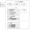
- FIG. 19 is a block diagram illustrating a configuration example of the stereo image capturing device 1B according to the sixth embodiment.
- the movement direction detection unit 15 includes a GPS (Global Positioning System) or an inertial sensor, and detects the movement direction of the imaging unit 3.
- GPS Global Positioning System
- GPS is a system that measures the position of a person using radio waves from the US Department of Defense artificial satellite, and can measure latitude and longitude with accuracy of several tens of meters from the difference in arrival time from three or more satellites. It is used for automobile navigation. The relative position change (moving direction) can be measured with higher accuracy.
- an acceleration sensor such as a piezoelectric type or a capacitance type can be used as the inertial sensor.
- the position change can be measured by integrating the detected acceleration twice.
- the overlapping area setting unit 6 sets an overlapping area on the same side as the moving direction detected by the moving direction detecting unit 15. Other configurations are the same as those of the first embodiment.
- FIG. 20 shows a processing flow example of image capturing according to the sixth embodiment.
- a feature point extraction step (S150) to camera movement direction determination step (S170), and a movement direction detection step (S152) is added instead.
- the moving direction detection step (S152) the moving direction of the photographing unit 3 is detected using a GPS sensor or an inertial sensor.
- the overlapping direction setting step (S180) an overlapping region is set on the same side as the moving direction detected in the moving direction detection step (S152).
- Other processes are the same as those in the first embodiment.
- the first shot image 28 can be displayed in the display area 26 when the shooting is completed (when the object is made a round).
- the overlap area setting unit 6 An overlapping area is set as a round image overlapping area 28c in the captured image 28. For example, if the distance between the shooting position in the live image 25 and the shooting position in the first shooting image 28 is equal to or less than the distance between the shooting position in the live image 25 and the shooting position in the previous shooting image 27, the live image and the first shooting image 28 Corresponds to a case where an overlapping region is found.
- the overlap ratio is calculated from the distance between the shooting position in the live image 25 and the shooting position in the first shot image 28.
- the display unit 4 displays the first shot image 28 and the live image 25 so as to overlap each other in the round image overlap area 28c.
- a stereo image shooting apparatus capable of appropriately determining an overlapping area between the previous shot image and the current shot image and its Can provide a method.
- the overlapping area setting unit sets the overlapping area on the same side as the input moving direction. Differences from the first embodiment will be mainly described.
- FIG. 21 is a block diagram illustrating a configuration example of the stereo image photographing device 1C according to the seventh embodiment.
- the overlapping area setting unit 6 sets an overlapping area by an input from the photographer.
- the overlapping area setting unit 6 the overlapping area 23 is set in the previous captured image 21.
- the overlap area 23 is set for the overlap ratio and the overlap direction.
- the moving direction of the imaging unit 3 can be input in advance, and the moving direction input by the photographer is set as the overlapping direction.
- the previously captured image 21 is displayed with an overlapping area 23 surrounded by a frame.
- the photographer clicks the confirmation button on the display screen with the mouse the overlapping ratio and the overlapping direction are determined, and the overlapping area 23 is set in the previous captured image 21.
- Other configurations are the same as those of the first embodiment.
- FIG. 22 shows an example of a processing flow of image capturing according to the seventh embodiment.
- the overlapping direction is set together with the overlapping ratio by the photographer's input.
- Other processes are the same as those in the first embodiment.
- the first shot image 28 can be displayed in the display area 26 when the shooting is completed (when the object is made a round).
- the overlap area setting unit 6 sets the round image overlap area 28 c in the first shot image 28.
- the round image overlapping area 28c is set on the side opposite to the moving direction of the photographing unit 3 input by the photographer, and the overlapping ratio is set to be the same as the initial image overlapping area 28a.
- “turning once” means moving to the same direction and reaching a position where the shooting from all directions planned by the current shooting is completed. For example, when shooting from 12 directions is scheduled, this means that the 12th shooting position has been reached.
- the display unit 4 displays the first shot image 28 and the live image 25 so as to overlap each other in the round image overlap area 28c.
- a stereo image shooting apparatus capable of appropriately determining an overlapping area between the previous shot image and the current shot image and its Can provide a method.
- the present invention can also be realized as a stereo image capturing method invention described in the flowcharts of the above embodiments and the like, and a program for causing a stereo image capturing apparatus to execute the method invention.
- the program may be stored and used in a built-in storage unit of the stereo image photographing device, may be stored and used in an external storage device, or may be downloaded from the Internet and used. Moreover, it is realizable also as a recording medium which recorded the said program.
- the overlapping display of the last-time captured image, the previous captured image, and the live image described in the second embodiment can be applied to the third to seventh embodiments.
- the deviation correction image described in the third embodiment, the first captured image described in the fourth embodiment, the previous captured image and the live image described in the fifth embodiment, and the display for changing the positions of these frames are displayed.
- This can also be applied to the sixth embodiment or the seventh embodiment.
- the image processing flow can be changed as appropriate.
- the example in which the overlap ratio is set before the live image acquisition has been described. However, it may be set in advance before shooting. Further, the feature point tracking step in the first to fifth embodiments can be omitted.
- the position may be moved while photographing a stereo image at a position slightly shifted left and right at each photographing position, and photographing may be performed while overlapping with other stereo images.
- the moving direction is both the vertical direction and the horizontal direction
- the overlapping area may be set and displayed as the photographing side overlapping area in FIG.
- the live image is temporarily stored.
- the live image may be stored so as to be reproducible like a video image.
- the number of shots, the overlapping ratio, and the like can be changed as appropriate.
- the present invention can be used for photographing for three-dimensional measurement of a measurement object and photographing all-around images.
Landscapes
- Engineering & Computer Science (AREA)
- Multimedia (AREA)
- Signal Processing (AREA)
- Physics & Mathematics (AREA)
- General Physics & Mathematics (AREA)
- Theoretical Computer Science (AREA)
- Studio Devices (AREA)
- Television Signal Processing For Recording (AREA)
- Stereoscopic And Panoramic Photography (AREA)
Applications Claiming Priority (2)
| Application Number | Priority Date | Filing Date | Title |
|---|---|---|---|
| JP2009-133378 | 2009-06-02 | ||
| JP2009133378A JP5363878B2 (ja) | 2009-06-02 | 2009-06-02 | ステレオ画像撮影装置及びその方法 |
Publications (1)
| Publication Number | Publication Date |
|---|---|
| WO2010140513A1 true WO2010140513A1 (ja) | 2010-12-09 |
Family
ID=43297649
Family Applications (1)
| Application Number | Title | Priority Date | Filing Date |
|---|---|---|---|
| PCT/JP2010/058885 Ceased WO2010140513A1 (ja) | 2009-06-02 | 2010-05-26 | ステレオ画像撮影装置及びその方法 |
Country Status (3)
| Country | Link |
|---|---|
| JP (1) | JP5363878B2 (enExample) |
| KR (1) | KR20120036908A (enExample) |
| WO (1) | WO2010140513A1 (enExample) |
Cited By (4)
| Publication number | Priority date | Publication date | Assignee | Title |
|---|---|---|---|---|
| JPWO2012096163A1 (ja) * | 2011-01-13 | 2014-06-09 | パナソニック株式会社 | 画像処理装置、画像処理方法、及びそのプログラム |
| WO2014157348A1 (ja) * | 2013-03-26 | 2014-10-02 | 凸版印刷株式会社 | 画像処理装置、画像処理システム、画像処理方法及び画像処理プログラム |
| CN111105351A (zh) * | 2019-12-13 | 2020-05-05 | 华中科技大学鄂州工业技术研究院 | 一种视频序列影像拼接方法及装置 |
| JP2021193634A (ja) * | 2019-06-19 | 2021-12-23 | 株式会社リコー | 情報処理システム、情報処理方法及び情報処理プログラム |
Families Citing this family (2)
| Publication number | Priority date | Publication date | Assignee | Title |
|---|---|---|---|---|
| TWI435593B (zh) * | 2010-12-30 | 2014-04-21 | Altek Corp | 立體影像拍攝方法 |
| CN104880905B (zh) * | 2015-05-13 | 2017-11-24 | 北京康得新三维科技有限责任公司 | 一种移轴立体摄影装置及方法 |
Citations (6)
| Publication number | Priority date | Publication date | Assignee | Title |
|---|---|---|---|---|
| JPH11136575A (ja) * | 1997-08-20 | 1999-05-21 | Ricoh Co Ltd | 撮像装置及び撮像画像合成方法 |
| JP2000299804A (ja) * | 1999-04-12 | 2000-10-24 | Casio Comput Co Ltd | パノラマ撮影方法及び撮像装置 |
| JP2002090820A (ja) * | 2000-09-14 | 2002-03-27 | Canon Inc | 画像処理装置、画像処理システム、制御方法、及び記憶媒体 |
| JP2007183256A (ja) | 2005-12-08 | 2007-07-19 | Topcon Corp | 画像処理装置及びその方法 |
| JP2008098754A (ja) * | 2006-10-06 | 2008-04-24 | Olympus Imaging Corp | 撮像装置、画像再生装置および撮像画像の表示方法 |
| JP2009133378A (ja) | 2007-11-29 | 2009-06-18 | Toyota Motor Corp | トルク変動吸収装置 |
Family Cites Families (1)
| Publication number | Priority date | Publication date | Assignee | Title |
|---|---|---|---|---|
| JP4889351B2 (ja) * | 2006-04-06 | 2012-03-07 | 株式会社トプコン | 画像処理装置及びその処理方法 |
-
2009
- 2009-06-02 JP JP2009133378A patent/JP5363878B2/ja not_active Expired - Fee Related
-
2010
- 2010-05-26 KR KR1020117031677A patent/KR20120036908A/ko not_active Withdrawn
- 2010-05-26 WO PCT/JP2010/058885 patent/WO2010140513A1/ja not_active Ceased
Patent Citations (6)
| Publication number | Priority date | Publication date | Assignee | Title |
|---|---|---|---|---|
| JPH11136575A (ja) * | 1997-08-20 | 1999-05-21 | Ricoh Co Ltd | 撮像装置及び撮像画像合成方法 |
| JP2000299804A (ja) * | 1999-04-12 | 2000-10-24 | Casio Comput Co Ltd | パノラマ撮影方法及び撮像装置 |
| JP2002090820A (ja) * | 2000-09-14 | 2002-03-27 | Canon Inc | 画像処理装置、画像処理システム、制御方法、及び記憶媒体 |
| JP2007183256A (ja) | 2005-12-08 | 2007-07-19 | Topcon Corp | 画像処理装置及びその方法 |
| JP2008098754A (ja) * | 2006-10-06 | 2008-04-24 | Olympus Imaging Corp | 撮像装置、画像再生装置および撮像画像の表示方法 |
| JP2009133378A (ja) | 2007-11-29 | 2009-06-18 | Toyota Motor Corp | トルク変動吸収装置 |
Cited By (10)
| Publication number | Priority date | Publication date | Assignee | Title |
|---|---|---|---|---|
| JPWO2012096163A1 (ja) * | 2011-01-13 | 2014-06-09 | パナソニック株式会社 | 画像処理装置、画像処理方法、及びそのプログラム |
| WO2014157348A1 (ja) * | 2013-03-26 | 2014-10-02 | 凸版印刷株式会社 | 画像処理装置、画像処理システム、画像処理方法及び画像処理プログラム |
| CN105027159A (zh) * | 2013-03-26 | 2015-11-04 | 凸版印刷株式会社 | 图像处理装置、图像处理系统、图像处理方法及图像处理程序 |
| JPWO2014157348A1 (ja) * | 2013-03-26 | 2017-02-16 | 凸版印刷株式会社 | 画像処理装置、画像処理システム、画像処理方法及び画像処理プログラム |
| US10068339B2 (en) | 2013-03-26 | 2018-09-04 | Toppan Printing Co., Ltd. | Image processing device, image processing system, image processing method and image processing program |
| CN105027159B (zh) * | 2013-03-26 | 2018-10-26 | 凸版印刷株式会社 | 图像处理装置、图像处理系统、图像处理方法及图像处理程序 |
| JP2021193634A (ja) * | 2019-06-19 | 2021-12-23 | 株式会社リコー | 情報処理システム、情報処理方法及び情報処理プログラム |
| JP7180739B2 (ja) | 2019-06-19 | 2022-11-30 | 株式会社リコー | 情報処理装置、情報処理システム、情報処理方法及び情報処理プログラム |
| CN111105351A (zh) * | 2019-12-13 | 2020-05-05 | 华中科技大学鄂州工业技术研究院 | 一种视频序列影像拼接方法及装置 |
| CN111105351B (zh) * | 2019-12-13 | 2023-04-18 | 华中科技大学鄂州工业技术研究院 | 一种视频序列影像拼接方法及装置 |
Also Published As
| Publication number | Publication date |
|---|---|
| JP2010283466A (ja) | 2010-12-16 |
| KR20120036908A (ko) | 2012-04-18 |
| JP5363878B2 (ja) | 2013-12-11 |
Similar Documents
| Publication | Publication Date | Title |
|---|---|---|
| JP5100360B2 (ja) | 画像処理装置 | |
| US7489335B2 (en) | Photographic apparatus with function of image correction and method thereof | |
| JP5362189B2 (ja) | 画像処理装置及びその処理方法 | |
| USRE43700E1 (en) | Virtual reality camera | |
| CN101753818B (zh) | 成像设备和成像方法 | |
| JP5027747B2 (ja) | 位置測定方法、位置測定装置、およびプログラム | |
| JP5027746B2 (ja) | 位置測定方法、位置測定装置、およびプログラム | |
| JP5363878B2 (ja) | ステレオ画像撮影装置及びその方法 | |
| WO2004113836A1 (ja) | 撮影映像表示方法 | |
| JP2004531113A (ja) | 注釈記入による全方位性3次元イメージデータ獲得装置、その方法及び感光範囲の拡大方法 | |
| JP2010219825A (ja) | 三次元計測用画像撮影装置 | |
| JP2009042162A (ja) | キャリブレーション装置及びその方法 | |
| JP4851239B2 (ja) | 画像処理装置及びその処理方法 | |
| JP2007147457A (ja) | 三次元形状演算装置及び三次元形状演算方法 | |
| JP3842988B2 (ja) | 両眼立体視によって物体の3次元情報を計測する画像処理装置およびその方法又は計測のプログラムを記録した記録媒体 | |
| JP3696335B2 (ja) | 複数枚の画像の各計測点の対応づけ方法 | |
| JP4006296B2 (ja) | 写真測量による変位計測方法及び変位計測装置 | |
| JPH10320558A (ja) | キャリブレーション方法並びに対応点探索方法及び装置並びに焦点距離検出方法及び装置並びに3次元位置情報検出方法及び装置並びに記録媒体 | |
| JPH11351865A (ja) | 画像計測処理方法並びに装置及び画像計測処理プログラムを記録した記録媒体 | |
| JP5885974B2 (ja) | 空中写真画像データの対応点設定方法及び対応点設定装置並びに対応点設定プログラム | |
| JP2006113001A (ja) | 写真測量による3次元計測方法及び装置 | |
| JP4550081B2 (ja) | 画像測定方法 | |
| JP4809134B2 (ja) | 画像処理装置及びその処理方法 | |
| JP4851240B2 (ja) | 画像処理装置及びその処理方法 | |
| JP2020167499A (ja) | 写真撮影支援装置 |
Legal Events
| Date | Code | Title | Description |
|---|---|---|---|
| 121 | Ep: the epo has been informed by wipo that ep was designated in this application |
Ref document number: 10783297 Country of ref document: EP Kind code of ref document: A1 |
|
| NENP | Non-entry into the national phase |
Ref country code: DE |
|
| WWE | Wipo information: entry into national phase |
Ref document number: 2010783297 Country of ref document: EP |
|
| ENP | Entry into the national phase |
Ref document number: 20117031677 Country of ref document: KR Kind code of ref document: A |