WO2010140428A1 - 接合方法 - Google Patents
接合方法 Download PDFInfo
- Publication number
- WO2010140428A1 WO2010140428A1 PCT/JP2010/056775 JP2010056775W WO2010140428A1 WO 2010140428 A1 WO2010140428 A1 WO 2010140428A1 JP 2010056775 W JP2010056775 W JP 2010056775W WO 2010140428 A1 WO2010140428 A1 WO 2010140428A1
- Authority
- WO
- WIPO (PCT)
- Prior art keywords
- main
- metal member
- joining
- main joining
- stirring
- Prior art date
- Legal status (The legal status is an assumption and is not a legal conclusion. Google has not performed a legal analysis and makes no representation as to the accuracy of the status listed.)
- Ceased
Links
Images





Classifications
-
- B—PERFORMING OPERATIONS; TRANSPORTING
- B23—MACHINE TOOLS; METAL-WORKING NOT OTHERWISE PROVIDED FOR
- B23K—SOLDERING OR UNSOLDERING; WELDING; CLADDING OR PLATING BY SOLDERING OR WELDING; CUTTING BY APPLYING HEAT LOCALLY, e.g. FLAME CUTTING; WORKING BY LASER BEAM
- B23K20/00—Non-electric welding by applying impact or other pressure, with or without the application of heat, e.g. cladding or plating
- B23K20/12—Non-electric welding by applying impact or other pressure, with or without the application of heat, e.g. cladding or plating the heat being generated by friction; Friction welding
-
- B—PERFORMING OPERATIONS; TRANSPORTING
- B23—MACHINE TOOLS; METAL-WORKING NOT OTHERWISE PROVIDED FOR
- B23K—SOLDERING OR UNSOLDERING; WELDING; CLADDING OR PLATING BY SOLDERING OR WELDING; CUTTING BY APPLYING HEAT LOCALLY, e.g. FLAME CUTTING; WORKING BY LASER BEAM
- B23K20/00—Non-electric welding by applying impact or other pressure, with or without the application of heat, e.g. cladding or plating
- B23K20/12—Non-electric welding by applying impact or other pressure, with or without the application of heat, e.g. cladding or plating the heat being generated by friction; Friction welding
- B23K20/122—Non-electric welding by applying impact or other pressure, with or without the application of heat, e.g. cladding or plating the heat being generated by friction; Friction welding using a non-consumable tool, e.g. friction stir welding
- B23K20/1225—Particular aspects of welding with a non-consumable tool
Definitions
- the present invention relates to a joining method for joining metal members together.
- Friction stir welding is known as a method for joining metal members. Friction stir welding is a process of rotating a rotating tool along the abutting portion between metal members, and plastically flowing the metal at the abutting portion by frictional heat between the rotating tool and the metal member, so that the metal members are solid-phased. It is what is joined.
- a rotating tool is generally formed by protruding a stirring pin (probe) on the lower end surface of a shoulder portion having a cylindrical shape.
- Patent Document 1 discloses a first main joining step in which friction stir welding is performed from the front surface side of the metal member to be bonded to the metal member to be bonded formed by abutting metal members, and friction from the back surface side.
- a technique for performing a second main joining step for stir welding is disclosed.
- friction stir welding is performed under the same conditions (pushing amount, feed speed, etc. of the rotary tool) using an equivalent rotary tool. According to this joining method, since friction stir can be performed over the entire depth direction of the abutting portion, the water tightness and air tightness of the joined portion can be enhanced.
- the first main joining step of the conventional joining method when a rotary tool is pushed in from the surface side of the metal member to be joined and friction stir welding is performed, a plasticized region is formed on the surface of the metal member to be joined.
- heat is applied to the metal member to be joined by a rotating tool that rotates at high speed, and then the metal member is cooled, so that the surface side of the metal member to be joined may be deformed into a concave shape due to thermal contraction.
- the metal member to be bonded and the table on which the metal member to be bonded is placed are in surface contact. It is discharged to the table from the entire back surface of the member (heat removal).
- the metal member to be joined is warped due to thermal shrinkage in the first main joining step, so that friction stir welding is performed with a gap formed between the metal member to be joined and the table. Will do.
- the second main joining step the number of heat removal is reduced compared to the first main joining step because there are fewer paths through which heat is released.
- the warpage is excessively returned, and the back surface of the metal member to be joined is concave. Deform.
- the amount of heat remaining in the metal member to be bonded becomes unbalanced, so that the metal member to be bonded is distorted. there were.
- an object of the present invention is to provide a joining method capable of improving the flatness of a metal member in friction stir welding for joining a pair of metal members.
- the joining method according to the present invention that solves such problems is a first main joining in which friction stir welding is performed by moving the main welding rotary tool from the surface side of the metal member along the abutting portion between the metal members. And a second main joining step for performing friction stir welding by moving the main welding rotary tool from the back side of the metal member along the abutting portion after the first main joining step.
- the amount of heat input to the metal member in the second main joining step is set to be smaller than the amount of heat input to the metal member in the first main joining step.
- the main joining rotary tool used in the second main joining step is smaller than the main joining rotating tool used in the first main joining step. Further, in the second main joining step, it is preferable to perform the friction stir welding at a feed rate faster than the feed rate of the rotary tool for main joining in the first main joining step. According to such a joining method, the amount of heat input in the second main joining process can be easily set to be small.
- the friction stir welding is performed while the stirring pin of the rotary tool for main joining is inserted into the plasticized region formed in the first main joining step. According to this joining method, since the plasticized regions overlap and the tip side of the plasticized region is frictionally stirred again, the airtightness and watertightness of the joined portion can be improved.
- the first main joining step and the second main joining step are performed in a state where the metal member is fixed to the table by a fixing jig. According to this joining method, the workability of friction stir welding can be improved.
- the rotating tool for main joining includes a shoulder portion made of a metal harder than the metal member, a stirring pin protruding in the center of a lower end surface of the shoulder portion and formed in a tapered truncated cone shape, and the stirring It is preferable that the ratio of the length of the stirring pin with respect to the maximum outer diameter of the stirring pin is set to 1.33 to 2.03. .
- the stir pin is not easily broken and the friction stir can be performed up to a deep position of the metal member. If this ratio is less than 1.33, the load on the friction stirrer is increased, which is inappropriate. In addition, the stirring pin becomes short, and it becomes difficult to perform friction stirring to the depth of the metal member. On the other hand, when this ratio is larger than 2.03, the stirring pin is easily broken.
- the rotating tool for main joining includes a shoulder portion made of a metal harder than the metal member, a stirring pin protruding in the center of a lower end surface of the shoulder portion and formed in a tapered truncated cone shape, and the stirring And a ratio of the maximum outer diameter of the stirring pin to the minimum outer diameter of the stirring pin is set to 2.00 to 2.67. preferable.
- the rotating tool for main joining includes a shoulder portion made of a metal harder than the metal member, a stirring pin protruding in the center of a lower end surface of the shoulder portion and formed in a tapered truncated cone shape, and the stirring It is preferable that a ratio of an outer diameter of the shoulder portion to a maximum outer diameter of the stirring pin is set to 1.56 to 2.14. .
- the stirring pin is more difficult to break, and burrs generated by friction stirring can be reduced. If this ratio is less than 1.56, the metal overflows from the shoulder portion and surface defects occur. On the other hand, if this ratio is larger than 2.14, the load on the friction stirrer is increased, which is inappropriate.
- a stirrer for stirring is formed on the lower end surface of the shoulder portion so as to project in a spiral shape in plan view so as to surround the periphery of the stirring pin. According to this joining method, the stirring efficiency of the friction stir welding can be increased.
- the metal with respect to the abutting portion by using a temporary joining rotating tool smaller than the main joining rotating tool used in the first main joining step. It is preferable to perform the temporary joining process which performs friction stir welding from the surface side of a member.
- the metal is applied to the abutting portion. It is preferable to perform the temporary joining process which performs friction stir welding from the back surface side of a member.
- this joining process can be performed in a state where a pair of metal members are temporarily attached, workability can be improved.
- a friction stirring start position or an end position is provided on the tab material arranged on the side of the abutting portion between the metal members, and after the first main joining step, A repairing process in which friction stir is performed using at least a repairing rotating tool smaller than the main welding rotating tool for at least a portion adjacent to the tab material in the plasticized region formed in the first main welding process. Preferably it is done.
- a friction stir start position or an end position is provided on the tab material arranged on the side of the abutting portion between the metal members, and after the second main joining step, A repairing step in which friction stir is performed using at least a repairing rotating tool smaller than the main welding rotating tool for at least a portion adjacent to the tab material in the plasticized region formed in the second main welding step. Preferably it is done.
- the joining defect can be repaired to improve the air tightness and water tightness of the joined portion.
- a highly flat metal member can be easily formed.
- the metal members 1a and 1b are plate-like members having a rectangular shape in cross-section, and are made of a friction-stirring metal material such as aluminum, aluminum alloy, copper, copper alloy, titanium, titanium alloy, magnesium, and magnesium alloy.
- one metal member 1a and the other metal member 1b are formed of a metal material having the same composition.
- matched the metal member 1a and the metal member 1b is called the to-be-joined metal member 1
- the surface of the to-be-joined metal member 1 is the surface A
- the back is the back B
- one side is the 1st side C
- the other The side surface is also referred to as the second side surface D.
- the 1st tab material 2 and the 2nd tab material 3 are arrange
- limiting in particular in the material of the 1st tab material 2 and the 2nd tab material 3 In this embodiment, it forms with the metal material of the same composition as the to-be-joined metal member 1.
- the thickness dimension is the same as the thickness dimension of the to-be-joined metal member 1 in the butt
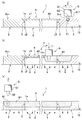
- temporary joining rotary tool F temporary joining step
- main joining rotary tool G main joining step
- a rotating tool F for temporary joining shown in FIG. 2A is made of a metal material harder than the metal member 1 to be joined, such as tool steel, and has a cylindrical shoulder portion F1 and a lower end face F11 of the shoulder portion F1. And an agitating pin (probe) F2 provided in a protruding manner.
- the size and shape of the temporary bonding rotary tool F may be set according to the material and thickness of the metal member 1 to be bonded, but at least the main bonding rotating tool G used in the first main bonding step described later. (Refer to FIG. 2B). This makes it possible to perform temporary bonding with a load smaller than that of the main bonding, so that it is possible to reduce the load applied to the friction stirrer at the time of temporary bonding. Since the moving speed (feeding speed) can be made faster than the moving speed of the main joining rotary tool G, the working time and cost required for temporary joining can be reduced.
- the lower end surface F11 of the shoulder portion F1 is a portion that plays a role of pressing the plastic fluidized metal and preventing scattering to the surroundings, and is formed in a concave shape in this embodiment.
- the stirring pin F2 hangs down from the center of the lower end surface F11 of the shoulder portion F1, and is formed into a tapered truncated cone shape in this embodiment.
- a stirring blade engraved in a spiral shape is formed on the peripheral surface of the stirring pin F2.
- the maximum outer diameter (upper diameter) X 2 is the maximum outer diameter of the stirring pin G2 of the rotary tool G for the joint (upper end diameter) Y 2 smaller than, and the minimum outer diameter (bottom diameter) X 3 is smaller than the minimum outer diameter (bottom diameter) Y 3 of the stirring pin G2.
- the length L A of the stirring pin F2 is set to 3 to 15% of the thickness t (see (c) of FIG. 1) of the metal member 1 to be joined at the abutting portion J1 (see (a) of FIG. 1). desirable, at least, it is desirable to be smaller than the length L B of the stirring pin G2 of the joining rotation tool G.
- a rotating tool G for main joining shown in FIG. 2B is made of a metal material harder than the metal member 1 to be joined, such as tool steel, and a shoulder part G1 having a columnar shape, and a lower end face G11 of the shoulder part G1. And an agitating pin (probe) G2 provided in a protruding manner.
- the lower end surface G11 of the shoulder portion G1 is formed in a concave shape like the temporary joining rotary tool F.
- the stirring pin G2 hangs down from the center of the lower end surface G11 of the shoulder portion G1, and is formed into a tapered truncated cone shape in this embodiment.
- a stirring blade engraved in a spiral shape is formed on the peripheral surface of the stirring pin G2.
- the length L B of the stirring pin G2 is preferably set to be 1/2 or more 3/4 of the thickness t of the bonding metal member 1 in the butting portion J1 (see FIG. 1 (c)) .
- the bonding method according to this embodiment includes (1) a first preparation step, (2) a first preliminary step, (3) a first main bonding step, (4) a second preparation step, and (5) a first.
- the first preliminary step and the first main joining step are steps executed from the surface A side of the metal member 1 to be joined, and the second preliminary step and the second main joining step are the metal to be joined. This is a process executed from the back surface B side of the member 1.
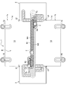
- the first preparation step is a step of preparing a contact member (first tab member 2 and second tab member 3) provided with a friction stirring start position and an end position of the metal members 1 to be bonded.
- the tab material arranging step of arranging the first tab material 2 and the second tab material 3 on both sides of the abutting portion J1, and the first tab material 2 and the second tab material 3 are temporarily joined to the metal member 1 to be joined by welding.
- a welding process and a fixing process for fixing the bonded metal member 1 to the table are provided.
- the metal members 1a, 1b, the first tab material 2 and the second tab material 3 which have been subjected to the chamfering process are immersed in a degreasing treatment liquid, and oils and fats such as processing oil adhering to the surface where each member is abutted Remove minutes and dirt.
- the end surfaces 11 and 11 where the metal member 1a and the metal member 1b are abutted, and the metal members 1a and 1b where the metal member 1 to be joined, the first tab material 2 and the second tab material 3 are abutted.
- the degreasing process is performed on the side surface 14, the contact surface 21 of the first tab member 2, and the contact surface 31 of the second tab member 3.
- at least the surface with which each member is abutted may be processed, but the surface adjacent to the abutting surface may be degreased.
- the end surface 11 of the other metal member 1b is brought into close contact with the end surface 11 of the one metal member 1a, and the surface 12 of the one metal member 1a and the other metal member
- the front surface 12 of 1b is flush
- the back surface 13 of one metal member 1a and the back surface 13 of the other metal member 1b are flush.
- the side surfaces 14 and 14 of one metal member 1a and the side surfaces 14 and 14 of the other metal member 1b are flush with each other.
- the first tab material 2 is arranged on one end side of the abutting portion J1 of the metal member 1 to be bonded, and the contact surface 21 is made to be the metal member 1 to be bonded.
- the second tab material 3 is disposed on the other end side of the abutting portion J1, and the contact surface 31 is brought into contact with the first side surface C of the metal member 1 to be joined.
- the surface 22 of the first tab member 2 and the surface 32 of the second tab member 3 are flush with the surface A of the metal member 1 to be joined, and the first tab.
- the back surface 23 of the material 2 and the back surface 33 of the second tab material 3 are flush with the back surface B of the bonded metal member 1.
- the corners 2a and 2a that is, the metal members 1a and 1b formed by the metal member 1 and the first tab member 2 are joined.
- the corner portion formed by the side surface 14 and the side surface 24 of the first tab member 2 is welded to join the metal member 1 to be joined and the first tab member 2, and the metal member 1 to be joined and the second tab member 3.
- the corners 3a, 3a that is, the corners formed by the side surface 14 of the metal members 1a, 1b and the side surface 34 of the second tab member 3) formed by welding are joined to the joined metal member 1 and the first The two tab material 3 is joined.
- the metal member 1 to be joined is placed on a table (base) 10 of a friction stirrer and restrained immovably using a fixing jig 15 such as a clamp.
- the form of the fixing jig 15 is not particularly limited, but a metal fitting 15a that contacts the surface A of the metal member 1 to be joined, a bolt 15b that is inserted through the metal fitting 15a, and a screw hole 15c into which the bolt 15b is screwed. It consists of.
- the four fixing jigs 15 are used, but the number is not limited.
- the first preliminary step is a step performed prior to the first main joining step, and in this embodiment, the abutting portion between the metal member 1 to be joined and the first tab member 2.
- the first tab material joining step for joining J2 the first temporary joining step for temporarily joining the abutting portion J1 of the metal member 1 to be joined, and the abutting portion J3 of the metal member 1 to be joined and the second tab material 3
- one temporary joining rotary tool F is moved so as to form a one-stroke writing movement trajectory (bead), and the abutting portions J2, J1, and J3 are moved. Friction stirring is performed continuously. That is, the stirring pin of the provisional joining rotary tool F which is inserted into the start position S P output friction stir F2 is moved to the end position E P without disengaging (in see FIG. 2 (a)) to the middle, first tab member A joining process, a 1st temporary joining process, and a 2nd tab material joining process are performed continuously.
- the start position S P output friction stir First tab member 2 is provided, although the end position E P provided on the second tab member 3, the position of the start position S P and the end position E P It is not intended to limit.
- the insertion speed (lowering speed) of the temporary joining rotary tool F is set according to the size and shape of the stirring pin F2, the material and thickness of the member on which the start position SP is provided, In this case, it is set within a range of 30 to 60 (mm / min).
- the moving speed (feeding speed) of the temporary bonding rotary tool F is set according to the size and shape of the stirring pin F2, the material and thickness of the metal member 1 to be bonded and the like to be frictionally stirred, In many cases, it is set within a range of 100 to 1000 (mm / min).
- the rotational speed at the time of movement of the temporary joining rotary tool F is the same as or lower than the rotational speed at the time of insertion.
- the axis of the shoulder portion F1 may be slightly inclined to the rear side in the traveling direction with respect to the vertical line. The direction of the joining rotary tool F can be easily changed, and complicated movement is possible.
- the metal around the stirring pin F2 is sequentially plastically fluidized, and the plastic fluidized metal is hardened again at a position away from the stirring pin F2.
- friction agitation is performed on the abutting portion J2 between the first tab material 2 and the metal member 1 to be joined. Specifically, by setting a friction stir route on the joint (boundary line) between the metal member 1 to be joined and the first tab member 2, and relatively moving the rotary tool F for temporary joining along the route, Friction stirring is performed on the abutting portion J2. In the present embodiment, the friction stir is continuously performed from the start point s2 to the end point e2 of the first tab material joining step without causing the temporary joining rotary tool F to be detached on the way.
- a start point is provided at the position of the end point e2 when the temporary joining rotary tool F is rotated to the right, and the position of the start point s2 when the temporary joining rotary tool F is rotated to the right.
- An end point may be provided at.
- the friction stir is continuously performed up to the start point s1 of the first temporary joining step without finishing the friction stirring at the end point e2, and the first tab material joining step is continued.
- the process proceeds to one temporary joining step. That is, friction stirring is continued without detaching the temporary bonding rotary tool F from the end point e2 of the first tab material bonding process to the start point s1 of the first temporary bonding process, and further, the temporary bonding rotary tool F at the start point s1.
- the process proceeds to the first temporary joining step without causing the separation.
- the friction stir route from the end point e2 of the first tab material joining process to the start point s1 of the first provisional joining process is set to the first tab material 2, and the temporary tool F for temporary joining is set as the first tab.
- a movement trajectory when moving from the end point e2 of the material joining step to the start point s1 of the first temporary joining step is formed on the first tab member 2. If it does in this way, since it becomes difficult to generate
- the first temporary joining step friction stir is performed on the abutting portion J1 of the metal member 1 to be joined. Specifically, a route for friction stirring is set on the joint (boundary line) of the metal member 1 to be joined, and the temporary tool rotation tool F is relatively moved along the route so that the entire length of the abutting portion J1 is obtained. Friction stirring is continuously performed throughout.
- the surface side plasticized region W0 is formed in the abutting portion J1.
- the friction stir is continuously performed from the start point s1 to the end point e1 of the first temporary joining step without causing the temporary joining rotary tool F to be detached on the way. This eliminates the need for removing the temporary joining rotary tool F during the first temporary joining step, thereby further improving the efficiency and speed of the preliminary joining work. Become.
- the friction stir is continuously performed up to the start point s3 of the second tab material joining step without ending the friction stirring at the end point e1. Transition to the two-tab material joining process. That is, the frictional stirring is continued without detaching the temporary joining rotary tool F from the end point e1 of the first temporary joining step to the start point s3 of the second tab material joining step, and further, the temporary joining rotary tool F is started at the start point s3. The process proceeds to the second tab material joining step without releasing the.
- the friction stir route from the end point e1 of the first temporary joining process to the start point s3 of the second tab material joining process is set to the second tab material 3, and the temporary tool F for temporary joining is set to the first.
- a movement locus when moving from the end point e1 of the temporary joining process to the start point s3 of the second tab material joining process is formed in the second tab material 3. If it does in this way, since it becomes difficult to generate
- friction agitation is performed on the abutting portion J3 between the metal member 1 to be joined and the second tab material 3. Specifically, by setting a friction stir route on the joint (boundary line) between the metal member 1 to be joined and the second tab member 3, and relatively moving the rotary tool F for temporary joining along the route, Friction stirring is performed on the abutting portion J3. In the present embodiment, the friction stir is continuously performed from the start point s3 to the end point e3 of the second tab member joining step without causing the temporary joining rotary tool F to be detached halfway.
- the start point s3 and the end point e3 of the second tab member joining step are set so that the metal member 1 to be joined is positioned on the right side in the traveling direction of the temporary joining rotary tool F. Set the position of. If it does in this way, since it becomes difficult to generate
- the start point and the end point of the second tab member joining process are arranged so that the metal member 1 to be joined is positioned on the left side in the traveling direction of the temporary tool F for temporary joining. It is desirable to set the position.
- a starting point is provided at the position of the end point e3 when the temporary joining rotary tool F is rotated to the right, and the position of the starting point s3 when the temporary joining rotary tool F is rotated to the right.
- An end point may be provided at.
- it is provided with end position E P on the extension of the seam appearing on the surface A side of the bonding metal member 1 (boundary line).
- the end position E P is also a friction stirring start position S M1 in a first main joining process described later.
- the temporary joining rotation tool F reaches the end position E P, it is raised while rotating the rotary tool F for temporary joining disengaging the stirring pin F2 from the end position E P with.
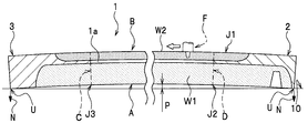
- FIG. 5 when the temporary welding rotary tool F rotated at high speed is inserted into the metal member 1 to be bonded, frictional heat is transmitted into the metal member 1 to be bonded (heat input). Since the metal member 1 to be bonded is in surface contact with the table 10, a part of the frictional heat is released (removed heat) from the entire back surface B of the metal member 1 to be bonded to the table 10 as indicated by an arrow N.
- the desorption rate of the rotary tool F for temporary bonding (rising speed), the size and shape of the stirring pin F2, but in which the end position E P is set according to the material and thickness of the members are provided, In many cases, it is set within a range of 30 to 60 (mm / min). Further, the rotational speed at the time of removal of the temporary joining rotary tool F is the same as or higher than the rotational speed at the time of movement.
- a pilot hole formation process is performed.
- Prepared hole forming step as shown in FIG. 2 (b), a step of forming a prepared hole P1 at the start position S M1 of the friction stir in the first of the welding process. That is, the pilot hole forming step is a step of forming the pilot hole P1 at a position where the stirring pin G2 of the main rotating tool G is to be inserted.
- the pilot hole P1 is provided for the purpose of reducing the insertion resistance (press-fit resistance) of the agitation pin G2 of the main welding rotary tool G, and in this embodiment, the agitation pin F2 (see FIG. 2 (see (a)) is formed by expanding the diameter of the hole h1 formed with a drill (not shown). If the punch hole h1 is used, the process of forming the pilot hole P1 can be simplified, and the working time can be shortened. Although there is no restriction
- the width Z 1 and depth Z 2 of the prepared hole P1 is stirring pin G2 of the size may be appropriately set according to the shape.
- pilot hole P1 is formed in the 2nd tab material 3
- matching part J2 , J3 may be preferably formed on the extended line of the joint (boundary line) of the metal member 1 to be bonded that appears on the surface A side of the metal member 1 to be bonded as in the present embodiment.
- a 1st main joining process is a process of joining the butting part J1 of the to-be-joined metal member 1 from the surface A side in earnest.
- the surface of the metal member 1 to be joined is used with respect to the abutting portion J1 in a temporarily joined state using the main joining rotating tool G shown in FIG. Friction stirring is performed from the A side.
- the stirring pin G2 of the joining rotation tool G inserted (press-fitted) into the prepared hole P1 formed in the start position S M1
- the inserted stirring pin G2 is moved to the end position E M1 without being removed halfway. That is, in the first main joining step, friction stirring is started from the pilot hole P1, and friction stirring is continuously performed to the end position E M1 .
- the second tab member 3 is provided with the friction stirring start position S M1 and the first tab member 2 is provided with the end position E M1 .
- the positions of the start position S M1 and the end position E M1 are as follows. It is not intended to limit.
- the main welding rotary tool G is positioned immediately above the pilot hole P1 (start position S M1 ), and then the main welding rotary tool G is rotated clockwise and lowered.
- the tip of the stirring pin G2 is inserted into the pilot hole P1.
- the stirring pin G2 enters the pilot hole P1
- the peripheral surface (side surface) of the stirring pin G2 comes into contact with the hole wall of the pilot hole P1, and the metal fluidizes plastically from the hole wall.
- the agitation pin G2 is press-fitted while pushing the plastic fluidized metal away from the peripheral surface of the agitation pin G2, so that it is possible to reduce the press-fitting resistance in the initial press-fitting stage. Since the stirring pin G2 contacts the hole wall of the pilot hole P1 and the frictional heat is generated before the shoulder portion G1 of the main rotating tool G contacts the surface of the second tab member 3, until the plastic fluidization occurs. It becomes possible to shorten the time. That is, it is possible to reduce the load on the friction stirrer, and in addition, it is possible to shorten the work time required for the main joining.
- the rotational speed (rotational speed at the time of insertion) of the main welding rotary tool G when the stirring pin G2 of the main welding rotary tool G is inserted into the friction stirring start position S M1 is the size / shape of the stirring pin G2, friction It is set in accordance with the material and thickness of the metal member 1 to be agitated, and is often set within the range of 70 to 700 (rpm). However, the friction from the start position S M1 It is desirable that the rotational speed of the main welding rotary tool G when the main welding rotary tool G is moved toward the stirring end position E M1 (the rotational speed at the time of movement) be higher.
- the moving speed (feeding speed) of the main rotating tool G for welding is set in accordance with the size and shape of the stirring pin G2, the material and thickness of the metal member 1 to be welded, etc. In many cases, it is set within a range of 30 to 300 (mm / min).
- the axis of the shoulder portion G1 may be slightly inclined to the rear side in the traveling direction with respect to the vertical line. The direction of the joining rotary tool G can be easily changed, and complex movement is possible.
- the first temporary bonding step is performed to be bonded. Since the joint between the metal members 1 is closed, it is difficult for cooling water to enter the abutting portion J1 of the metal member 1 to be joined, and therefore there is no possibility of deteriorating the quality of the joint portion.
- a friction stir route is set on the joint of the metal member 1 to be bonded (on the movement trajectory in the first temporary bonding process), and the main rotating tool along the route is connected.
- frictionally moving G friction stirring is continuously performed from one end of the abutting portion J1 to the other end.
- the main rotation tool G is relatively moved to the other end of the abutting portion J1
- the abutting portion J2 is moved across the abutting portion J2 while performing frictional stirring, and is then relatively moved toward the end position E M1 .
- the friction stirring end position E M1 is set on the extension line of the seam (boundary line) appearing on the surface A side of the metal member 1 to be joined, the friction stirring in the first main joining step is performed.
- the route of can be straight. If the route of friction stirring is made straight, the moving distance of the main welding rotary tool G can be minimized, so that the first main welding process can be performed efficiently. The wear amount of the tool G can be reduced.
- the left side in the traveling direction is the metal
- a tunnel-like cavity defect (hereinafter referred to as a tunnel-like cavity defect) is formed in the member 1b.
- the left side in the traveling direction is the shear side (the relative speed of the outer periphery of the rotating tool with respect to the bonded portion is a value obtained by adding the moving speed to the size of the tangential speed on the outer periphery of the rotating tool. Therefore, it is considered that the metal is vigorously stirred and softened at a high temperature to be easily discharged as burrs.
- the left side of the traveling direction is short of metal.
- the right side of the traveling direction that is, the metal member 1a side is the flow side (the relative speed of the outer periphery of the rotating tool with respect to the bonded portion is obtained by subtracting the magnitude of the moving speed from the magnitude of the tangential speed on the outer periphery of the rotating tool. Therefore, it is considered that the stirring of the metal is relatively weak and is not easily discharged as burrs, and a relatively dense plasticized region is formed.
- the right side in the traveling direction becomes the shear side, so that a tunnel-like cavity defect may be formed on the right side in the traveling direction.
- the left side in the traveling direction is the flow side, a relatively dense plasticized region is formed. If a bonding defect such as a tunnel-like cavity defect is formed in the metal member 1 to be bonded, it becomes a cause of reducing the airtightness and watertightness of the metal member 1 to be bonded.
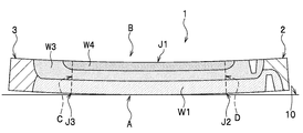
- FIG. 7 is a perspective view showing the first main joining process according to the first embodiment. As shown in FIG. 7, when the first preliminary process and the first main joining process described above are performed, the heat transferred to the metal member 1 is cooled and causes heat shrinkage. 1 is deformed into a concave shape on the surface A side.
- the second preparatory step is a step performed prior to the second preliminary step.
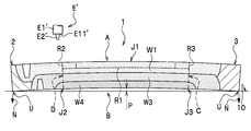
- the metal member to be bonded is obtained by reversing the front and back of the metal member 1 to be bonded. 1 is fixed to the table 10 with a fixing jig 15 (see FIG. 3). As shown in FIG. 8, when the metal member 1 to be bonded is fixed to the table 10, the metal member 1 to be bonded is warped (distorted), so that the edges U and U of the metal member 1 to be bonded and the table 10 are connected. A gap P is formed between the table 10 and the surface A of the metal member 1 to be joined.
- the second preliminary step is a step that is performed prior to the second main joining step, and in this embodiment, the abutting portion J2 between the metal member 1 to be joined and the first tab member 2.
- a first tab material joining step for joining the joint, a second temporary joining step for temporarily joining the abutting portion J1 of the joined metal member 1, and a joining portion J3 of the joined metal member 1 and the second tab material 3 are joined.
- the second main joining step is a step of fully joining the abutting portion J1 of the metal member 1 to be joined from the back surface B side.
- the joined metal member 1 is joined to the abutting portion J1 using the main joining rotating tool H. Friction stirring is performed from the back B side.
- the main rotating tool H for welding is made of a metal material harder than the metal member 1 to be joined, such as tool steel, and a shoulder portion H1 having a columnar shape, and the shoulder portion H1.
- a stirring pin (probe) H2 protruding from the lower end surface H11 is provided.
- the main-joining rotary tool H has a shape substantially the same as the main-joint rotary tool G used in the first main-joining step, and is formed with a size of about 80% of the main-joint rotary tool G.
- the main joining rotary tool H used in the second main joining step may be the same size as the main joining rotational tool G, but is preferably set smaller than the main joining rotational tool G.
- the main welding rotary tool H is appropriately set in consideration of the size of the main welding rotary tool G used in the first main bonding step, the warpage of the metal member 1 to be bonded, and the like.
- the stirring pin H2 of the rotary tool H for main welding is inserted (press-fitted) into the pilot hole P2 (start position S M2 ) provided in the second tab member 3, and the inserted stirring pin H2 is inserted in the middle. Is moved to the end position E M2 provided on the first tab member 2 without being separated. That is, in the second main joining step, friction agitation is started from the pilot hole P2, and friction agitation is continuously performed up to the end position EM2 .
- the main welding rotary tool H is positioned immediately above the pilot hole P2, and then the main welding rotary tool H is moved downward while rotating to the right of the stirring pin H2. Insert the tip into the pilot hole P2.
- the rotary tool H is relatively moved toward one end of the abutting portion J1 of the metal member 1 to be joined.
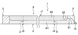
- the insertion depth of the stirring pin H2 is not particularly limited, but it is preferable to set the depth so that the stirring pin H2 contacts the surface-side plasticized region W1 as in the present embodiment.
- the rotation tool H for main joining is rotated rightward, and the 1st side C side of the to-be-joined metal member 1 is turned to the 2nd side D side. Since frictional stirring is performed, a relatively dense plasticized region is formed on the right side in the traveling direction, that is, on the metal member 1b side. Therefore, the tunnel-like cavity defect in the surface side plasticized region W1 formed by the first main joining process can be reliably sealed.
- the main welding rotary tool H when the main welding rotary tool H reaches the end position E M2 , the main welding rotary tool H is raised while rotating to disengage the stirring pin H2 from the end position E M2 . (See (c) of FIG. 9).
- the rotational speed at the time of detachment of the main joining rotary tool H is desirably higher than the rotational speed at the time of movement.
- the friction stirring end position E M2 (punch hole Q2) in the second main joining step is provided at a position away from the punch hole Q1, and the second so as to avoid the punch hole Q1. It is desirable to set a friction stirring route in the main joining step and move the stirring pin H2 of the main welding rotary tool H along the route.
- the second main joining step since the gap P is formed, there are fewer paths through which heat is released compared to the first main joining step. Therefore, in the second main joining step, the amount of heat removal is smaller than that in the first main joining step, but since the rotating tool H for main joining which is smaller than the rotating tool G for main joining is used, The amount of heat input is small compared to the main joining process.
- the tab material is excised.
- the amount of heat removal is reduced in the second main joining process due to the generation of the gap P, but the book using the main welding rotary tool H used in the second main joining process is used in the first main joining process.
- the amount of heat remaining in the bonded metal member 1 can be balanced in the first main joining step and the second main joining step.
- the amount of residual heat on the surface A side of the metal member 1 to be joined is (heat input in the first preliminary process + heat input in the first main joining process) ⁇ (heat removal in the first preliminary process + first The amount of heat removed in the main joining step).
- the residual heat quantity on the back B side is (heat input in the second preliminary process + heat input in the second main joining process) ⁇ (heat removal in the second preliminary process + second main joining process). (Heat removal amount)
- the remaining heat quantity in the first main joining step and the second main joining step is balanced, The to-be-joined metal member 1 can be made flat.
- the amount of heat input to the metal member 1 to be bonded is changed by changing the size of the rotary tools G and H for main bonding, the amount of heat input can be easily adjusted.
- the front side plasticizing region W1 is rubbed again by inserting the tip of the main welding rotating tool H into the surface side plasticizing region W1 formed in the first main joining step. Can be stirred. Thereby, the joining defect which may generate
- the friction stir welding can be performed without separating the metal members 1a and 1b from each other.
- the amount of heat input on the front surface side and the back surface side of the metal member 1 to be bonded is adjusted by changing the size of the rotating tool, but the present invention is not limited to this.
- the rotational tool on the back surface B side is increased by making the moving speed of the rotating tool on the back surface B side faster than that of the rotating tool on the front surface A side
- the amount of heat input can be reduced.
- the length of the trajectory for moving the rotating tool (the sum of the lengths of the friction agitation trajectory) is made shorter on the back surface B side than the front surface A side of the metal member 1 to be joined, so that the heat input amount on the back surface B side. Can be reduced.
- the friction agitation performed in the second main joining step may be set in consideration of the heat input amount, the heat removal amount, the size of the gap P in the first main joining step, the thickness of the metal member 1 to be joined, and the like. .
- a correction step is performed from the front surface A or the back surface B of the metal member 1 to be joined. Also good.
- friction agitation is performed from the convex surface side of the front surface A or the rear surface B of the bonded metal member 1 using a correction rotation tool (not shown).
- the straightening rotary tool has the same shape as the main joining rotary tool G, and a straightening rotary tool (not shown) smaller than the main joining rotary tool G is used.
- the movement path of the friction stirrer is not particularly limited, and may be performed on the abutting portion, or may be performed on a portion where warpage is large.
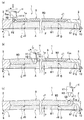
- the second embodiment includes (1) a first preparation step, (2) a first preliminary step, (3) a first main joining step, (4) a second preparation step, and (5) a second preparation step.
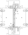
- the second repairing step is a step of repairing a joint defect that may be included in the backside plasticizing region W3 of the backside B of the metal member 1 to be joined.
- the friction stir for the first repair region R1 is intended to divide a tunnel defect that may be formed along the traveling direction of the main welding rotary tool H in the second main joining step. Is to be done. If the rotating tool for welding H is rotated to the right, a tunnel defect may occur on the left side in the traveling direction, and if it is rotated to the left, a tunnel defect may occur on the right side in the traveling direction.
- the first repair region R1 is set so as to include at least the upper portion of the surface-side plasticizing region W1 located on the left side in the traveling direction in plan view. Good.
- Friction stirring with respect to the second repair region R2 divides the oxide film caught in the back side plasticizing region W3 when the main welding rotary tool H crosses the abutting portion J2 in the second main joining step. It is done for the purpose.
- the end position E M2 of the friction stirring in the main joining step is provided in the first tab member 2 as in the present embodiment and the main rotating tool H is rotated to the right, the back side plasticization on the right side in the traveling direction is performed.
- There is a high possibility that an oxide film is caught in the upper part of the region W3, and when it is rotated counterclockwise, there is a high possibility that the oxide film is caught in the upper part of the back side plasticizing region W3 on the left side in the traveling direction.
- the back side plasticity located on the right side in the traveling direction in plan view in the back side plasticizing region W3 adjacent to the first tab member 2.
- the second repair region R2 may be set so as to include at least the upper portion of the conversion region W3.
- the distance d 5 from the joint between the metal member 1 to be bonded and the first tab member 2 to the edge of the second repair region R2 on the metal member 1 side is the maximum of the stirring pin H2 of the main rotating tool H for bonding. It is desirable to make it larger than the outer diameter.
- Friction stirring with respect to the third repair region R3 is performed for the purpose of dividing the oxide film caught in the back surface plasticizing region W3 when the main rotating tool H crosses the abutting portion J3. If the start position S M2 of the friction stir in the welding process as in the present embodiment is provided on the second tab member 3, when this joining rotation tool H has rotated clockwise the rear side to the left of the traveling direction There is a high possibility that an oxide film is caught in the upper part of the plasticizing region W3, and when it is rotated counterclockwise, there is a possibility that the oxide film is caught in the upper part of the back side plasticizing region W3 on the right side in the traveling direction.
- the third repair region R3 may be set so as to include at least the upper portion of the side plasticization region W3.
- the distance d 4 from the joint of the metal member 1 and the second tab member 3 to the edge of the third repair region R3 on the metal member 1 side is the maximum of the stirring pin H2 of the main rotating tool H. It is desirable to make it larger than the outer diameter.
- the repair rotary tool E is made of a metal material harder than the metal member 1 to be joined, such as tool steel, like the main welding rotary tool H, and has a cylindrical shoulder portion E1 and a lower end surface of the shoulder portion E1.
- a stirring pin (probe) E2 protruding from E11 is provided.
- the stirring pin E2 hangs down from the lower end surface of the shoulder portion E1, and in this embodiment, the stirring pin E2 is formed in a tapered truncated cone shape. In addition, a stirring blade engraved in a spiral shape is formed on the peripheral surface of the stirring pin E2.
- the repair rotary tool E is smaller than the main joining rotary tool H and larger than the temporary joining rotary tool F.
- the repair rotary tool E may be detached every time friction stirring for one repair area is completed, or a repair rotary tool E having a different form for each repair area may be used.
- the first repair area R1 and the second repair are performed by moving one repair rotary tool E so as to form a one-stroke writing movement trajectory (bead).
- Friction stirring is continuously performed on the region R2 and the third repair region R3. That is, in the second repairing process according to the present embodiment, the end without stirring pin E2 of repairing rotating tool E inserted into the starting position S R of the friction stirring (see (b) of FIG. 11) is detached in the middle It is moved to a position E R.
- the end position E R provided on the second tab member 3 the second repairing region R2, the first repairing region R1 , illustrate the case where the friction stir in the order of the third repair area R3, are not intended to limit the order of the position and the friction stir start position S R and the end position E R.
- the moving speed (feeding speed) of the repair rotary tool E is set according to the size and shape of the stirring pin E2, the material and thickness of the bonded metal member 1 to be frictionally stirred, and the like. In many cases, it is set within a range of 100 to 1000 (mm / min).
- the rotational speed at the time of movement of the repair rotary tool E is the same as or lower than the rotational speed at the time of insertion.
- the repair rotary tool E When the friction agitation with respect to the first repair region R1 is completed, the repair rotary tool E is moved to the third repair region R3 without being detached, and the friction agitation is performed with respect to the third repair region R3. If it does in this way, even if it is a case where the oxide film which exists between the to-be-joined metal member 1 and the 2nd tab material 3 is wound in the back surface side plasticization area
- region W3 it is possible to divide the said oxide film. Therefore, even in the back surface side plasticized region W3 adjacent to the second tab member 3, it becomes difficult to generate a bonding defect. If the third repair region R3 is larger than the region where friction stirring can be performed with the repair rotating tool E, the repair rotating tool E may be turned several times while shifting the friction stirring route. .
- the table 10 and the surface A of the metal member 1 to be joined are in contact with each other.
- the part is discharged from the surface A to the table 10 (heat removal).
- the first repair process is a process of repairing a joint defect that may be included in the surface side plasticized region W ⁇ b> 1 of the surface A of the metal member 1 to be joined.
- friction stirring is performed on at least the first repair region R1, the second repair region R2, and the third repair region R3 in the surface-side plasticized region W1.
- first repair region R1, the second repair region R2, and the third repair region R3 is the same as that of the second repair step, detailed description thereof is omitted.
- the repair tool is smaller than the repair rotary tool E used in the second repair process and larger than the temporary joint rotary tool F.
- Use rotating tool E ′ is made of a metal material harder than the metal member 1 to be joined, such as tool steel, and protruded from a shoulder portion E1 ′ having a columnar shape and a lower end surface E11 ′ of the shoulder portion E1 ′. And a stirring pin (probe) E2 ′.
- a first repair step as shown in FIGS. 14 and 15, insert the 'stirring pin E2 of' repairing rotating tool E to the starting position S R provided in place of the first tab member 2 (pressed) to Friction stirring is started and friction stirring is performed on the second repair region R2.
- friction stir is continuously performed on the first repair region R1 and the third repair region R3 as in the second repair step.
- the first repair process since the gap P is formed, there are fewer paths through which heat is released compared to the second repair process. Therefore, in the first repair process, the amount of heat removal is less than in the second repair process, but since the repair rotary tool E ′ is smaller than the repair rotary tool E, the first repair process uses the second repair process. Less heat input.
- the bonded metal member 1 when the bonded metal member 1 is released from the fixing jig 15 (see FIG. 14) and left after the first repair process, it is formed in the second repair process by thermal contraction. The warped portion is corrected and the bonded metal member 1 becomes flat.
- the amount of heat removal is reduced by generating the gap P, but the repair rotary tool E ′ used in the first repair process is set smaller than the repair rotary tool E used in the second repair process.
- the amount of heat remaining in the bonded metal member 1 can be balanced in the second repair process and the first repair process.
- produce in a repair process can be corrected, repairing the joint defect of the surface side plasticization area
- the trajectory of the rotating tool in the repair process is not limited to the above-described form.
- the repair may be performed by moving the rotating tool in a zigzag manner so as to cross the abutting portion J1.
- the main welding rotating tool K shown in FIG. 16 may be used as the rotating tool.
- the modified example is the same as that of the first embodiment except that the main rotating tool K for bonding is used. Therefore, the description of the overlapping parts is omitted.
- FIG. 16 is a view showing a modification of the rotary tool, in which (a) is a side sectional view and (b) is a bottom view.
- the main rotating tool K for welding is made of a metal material harder than the metal member 1 to be joined, such as tool steel, and has a shoulder portion K1 having a columnar shape, and the shoulder portion K1.
- a stirring pin (probe) K2 projecting from the lower end surface K11, an agitating protrusion K3 projecting from the lower end surface K11, and an agitating blade K4 engraved on the peripheral surface of the stirring pin K2 Has been.
- the stirring pin K2 hangs down from the center of the lower end surface K11 of the shoulder portion K1, and is formed into a tapered truncated cone shape in this embodiment.
- a stirring blade K4 that is spirally engraved to increase the stirring effect is formed.
- the length L 1 of the stirring pin K2, the maximum outer diameter Y 2 of the stirring pin K2, may be appropriately set according to the outside diameter Y 1 of the smallest outer diameter Y 3 and shoulder K1.
- a stirring ridge K3 protrudes from the lower end surface K11 of the shoulder portion K1 formed flat.
- the stirring protrusion K3 is formed in a spiral shape on the lower end surface K11 so as to surround the periphery of the stirring pin K2.
- the plastically fluidized metal flows toward the stirring pin K2, so that the efficiency of friction stirring can be increased.
- what is necessary is just to set suitably the length, the frequency
- the stirrer protrusion K3 protrudes from the lower end surface K11, so that friction stir is performed while collecting the plastic fluidized metal near the central portion of the stir pin K2. be able to. Thereby, while improving the efficiency of friction stirring, generation
- the base end portion of the stirring pin K2 is thick and the distal end side is tapered in the main rotating tool K for joining, the bending of the stirring pin K2 is prevented, and when the stirring pin K2 is press-fitted into a metal member. The press-fit resistance can be reduced.
- the stirring blade K4 is engraved on the outer peripheral surface of the stirring pin K2, friction stirring can be performed more efficiently.
- the metal member 200 was a rectangular parallelepiped having a size of 500 mm ⁇ 500 mm in plan view, and measurement was performed using two types of members having a thickness of 30 mm and 60 mm.
- the material of the metal member 200 is JIS standard 5052 aluminum alloy.
- Rotating tools of the same size were used for the front surface Za side and the back surface Zb side.
- the outer diameter of the shoulder portion is 20 mm
- the length of the stirring pin is 10 mm
- the size of the base of the stirring pin is 9 mm
- the size of the tip of the stirring pin is 6 mm. Things were used.
- the rotation speed of the rotary tool was set to 600 rpm, and the feed rate was set to 300 mm / min. Further, the pressing amount of the rotary tool was set constant on both the front surface Za side and the back surface Zb side. As shown in FIG.
- plasticized regions formed on the surface Za side are referred to as a plasticized region W21 to a plasticized region W23 from a small circle to a large circle, respectively.
- plasticized regions formed on the back surface Zb side are designated as plasticized regions W31 to W33 from the small circle to the great circle.
- Tables 1 to 4 The respective measurement results in this example are shown in Tables 1 to 4 below.
- Table 1 is a table showing measured values when the metal member 200 has a plate thickness of 30 mm and frictional stirring is performed from the surface Za side.
- “Before FSW” indicates the height difference between the central point j (reference j) and each point (point a to point h) before the friction stir.
- “After FSW” indicates a difference in height between the reference j and each point after performing frictional stirring of three circles with the reference j being zero.
- the “surface side deformation amount” indicates a value (after FSW ⁇ before FSW) at each point.
- the lowermost column of “Surface-side deformation amount” shows an average value of the points a to h. Negative values of “before FSW” and “after FSW” mean that they are located below the reference j.
- Table 2 shows that the thickness of the metal member 200 is 30 mm, and the metal member 200 that is warped (distorted) after frictional stirring of a small circle, a middle circle, and a great circle from the front side is performed. It is the table
- Before FSW indicates the level difference between the central point j ′ (reference j ′) and each point (a ′ to h ′) before the friction stir. As shown in FIG.
- “FSW1” indicates the difference in height between the reference j ′ and each point after the frictional stirring of the small circle (radius r1) with the reference j ′ set to zero.
- “Back side deformation amount 1” indicates a value (before FSW1 ⁇ FSW) at each point.
- the bottom column of “back surface side deformation amount 1” indicates an average value of the points a ′ to h ′.
- “FSW2” indicates a difference in height between the reference j ′ and each point after performing frictional stirring of the middle circle (radius r2) in addition to the small circle (radius r1) with the reference j ′ set to zero.
- “Back side deformation 2” indicates the value of (before FSW2 ⁇ FSW) at each point.
- the lowermost column of “back side deformation 2” shows the average value of the points a ′ to h ′.
- “FSW3” is based on the reference j ′ after the frictional stirring of the great circle (radius r3) in addition to the small circle (radius r1) and the middle circle (radius r2) with the reference j ′ set to zero. The height difference from the point is shown.
- “Back side deformation amount 3” indicates a value (before FSW3 ⁇ FSW) at each point.
- the bottom column of “back side deformation amount 3” indicates an average value of the points a ′ to h ′.
- Table 3 is a table showing measured values when the metal member 200 has a plate thickness of 60 mm and frictional stirring of small circles, middle circles, and great circles is performed from the surface side. Each item in Table 3 has substantially the same meaning as each item in Table 1.
- Table 4 is a table showing measured values when the thickness of the metal member 200 is 60 mm, and after frictional stirring is performed from the front side, frictional stirring is performed from the back side. Each item in Table 4 has substantially the same meaning as each item in Table 2.
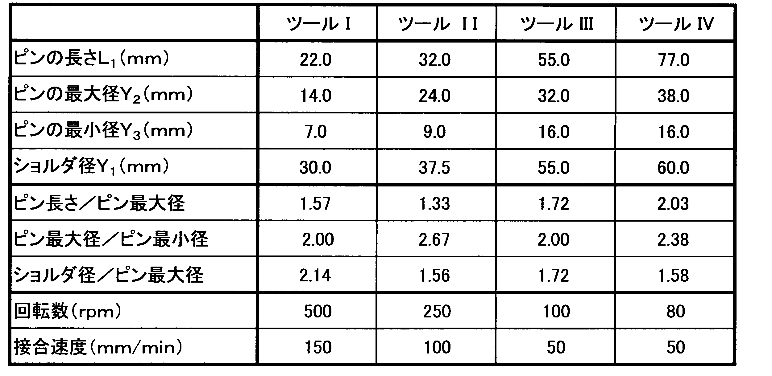
- Table 5 shows the conditions (dimensions) of each element of the main welding rotary tool K according to the above-described modification.
- Table 5 shows the pin (stirring pin) length, the maximum pin diameter, the minimum pin diameter, the shoulder diameter, and the dimensions of the tools I to IV having the same configuration as the rotary tool K for welding. The ratio, number of rotations and welding speed are shown.
- friction stir welding was performed on a pair of aluminum alloys (5052 aluminum alloy), and the status of each tool in the tools I to IV was observed.
- pin length / pin maximum diameter exceeds 2.03, the pin is broken. On the other hand, if the value of pin length / maximum pin diameter is less than 1.33, the load on the friction stirrer is increased, which is inappropriate and friction stirring cannot be performed to a deep position.
- the pin maximum diameter / minimum pin diameter exceeds 2.67, the maximum pin diameter is too large and the metal overflows, resulting in surface defects.
- the pin maximum diameter / pin minimum diameter is less than 2.00, the pin maximum diameter is smaller than the pin minimum diameter, so that heat input at the tip of the pin is insufficient and a joining defect occurs.
Landscapes
- Engineering & Computer Science (AREA)
- Mechanical Engineering (AREA)
- Pressure Welding/Diffusion-Bonding (AREA)
Abstract
Description
かかる接合方法によれば、第二の本接合工程における入熱量が、第一の本接合工程における入熱量よりも少なくなるため、接合された金属部材内に残存する熱量の不均衡を是正することができる。これにより、第二の本接合工程において金属部材が反ってしまうのを防ぐことができ、金属部材の平坦性を高めることができる。
また、前記第二の本接合工程を行う前に、前記第二の本接合工程で用いる前記本接合用回転ツールよりも小型の仮接合用回転ツールを用いて、前記突合部に対して前記金属部材の裏面側から摩擦攪拌接合を行う仮接合工程を行うことが好ましい。
また、前記第二の本接合工程では、前記金属部材同士の突合部の側方に配置されたタブ材に摩擦攪拌の開始位置又は終了位置を設け、前記第二の本接合工程の後に、前記第二の本接合工程で形成された塑性化領域のうち少なくとも前記タブ材に隣接する部分に対して前記本接合用回転ツールよりも小型の補修用回転ツールを用いて摩擦攪拌を行う補修工程を行うことが好ましい。
次に、本発明の実施形態について説明する。本実施形態では、図1に示すように、金属部材1a,1bを直線状に繋ぎ合せる場合を例示する。まず、接合すべき金属部材1a,1bを詳細に説明するとともに、この金属部材1a,1bを接合する際に用いられる第一タブ材2、第二タブ材3を詳細に説明する。
図1を参照して第一の準備工程を説明する。第一の準備工程は、接合すべき被接合金属部材1の摩擦攪拌の開始位置や終了位置が設けられる当て部材(第一タブ材2及び第二タブ材3)を準備する工程であり、本実施形態では、金属部材1a,1b、第一タブ材2及び第二タブ材3の油脂分等の汚れを取り除く脱脂工程と、金属部材1a,1bを突き合せる突合工程と、被接合金属部材1の突合部J1の両側に第一タブ材2、第二タブ材3を配置するタブ材配置工程と、第一タブ材2、第二タブ材3を溶接により被接合金属部材1に仮接合する溶接工程と、被接合金属部材1をテーブルに固定する固定工程を具備している。
第一の予備工程は、第一の本接合工程に先立って行われる工程であり、本実施形態では、被接合金属部材1と第一タブ材2との突合部J2を接合する第一タブ材接合工程と、被接合金属部材1の突合部J1を仮接合する第一の仮接合工程と、被接合金属部材1と第二タブ材3との突合部J3を接合する第二タブ材接合工程と、第一の本接合工程における摩擦攪拌の開始位置に下穴を形成する下穴形成工程とを具備している。
第一の本接合工程は、被接合金属部材1の突合部J1を表面A側から本格的に接合する工程である。本実施形態に係る第一の本接合工程では、図2の(b)に示す本接合用回転ツールGを使用し、仮接合された状態の突合部J1に対して被接合金属部材1の表面A側から摩擦攪拌を行う。
まず、図6の(a)に示すように、下穴P1(開始位置SM1)の直上に本接合用回転ツールGを位置させ、続いて、本接合用回転ツールGを右回転させつつ下降させて攪拌ピンG2の先端を下穴P1に挿入する。攪拌ピンG2を下穴P1に入り込ませると、攪拌ピンG2の周面(側面)が下穴P1の穴壁に当接し、穴壁から金属が塑性流動化する。このような状態になると、塑性流動化した金属を攪拌ピンG2の周面で押し退けながら、攪拌ピンG2が圧入されることになるので、圧入初期段階における圧入抵抗を低減することが可能となり、また、本接合用回転ツールGのショルダ部G1が第二タブ材3の表面に当接する前に攪拌ピンG2が下穴P1の穴壁に当接して摩擦熱が発生するので、塑性流動化するまでの時間を短縮することが可能となる。つまり、摩擦攪拌装置の負荷を低減することが可能となり、加えて、本接合に要する作業時間を短縮することが可能となる。
第二の準備工程は、第二の予備工程に先立って行われる工程であり、本実施形態では、被接合金属部材1の表裏を逆にして、被接合金属部材1を固定治具15(図3参照)でテーブル10に固定する。図8に示すように、被接合金属部材1をテーブル10に固定すると、被接合金属部材1が反って(歪んで)いるため、被接合金属部材1の縁部U,Uとテーブル10とが当接し、テーブル10と被接合金属部材1の表面Aとの間に間隙Pが形成される。
第二の予備工程は、第二の本接合工程に先だって行われる工程であり、本実施形態では、被接合金属部材1と第一タブ材2との突合部J2を接合する第一タブ材接合工程と、被接合金属部材1の突合部J1を仮接合する第二の仮接合工程と、被接合金属部材1と第二タブ材3との突合部J3を接合する第二タブ材接合工程と、第二の本接合工程における摩擦攪拌の開始位置に下穴を形成する下穴形成工程とを具備している。第二の予備工程は、被接合金属部材1の表裏を除いては、前記した第一の予備工程と略同等であるため、詳細な説明は省略する。
第二の本接合工程は、被接合金属部材1の突合部J1を裏面B側から本格的に接合する工程である。本実施形態に係る第二の本接合工程では、図9の(a)~(c)に示すように、本接合用回転ツールHを使用して、突合部J1に対して被接合金属部材1の裏面B側から摩擦攪拌を行う。
まず、図9の(a)に示すように、下穴P2の直上に本接合用回転ツールHを位置させ、続いて、本接合用回転ツールHを右回転させつつ下降させて攪拌ピンH2の先端を下穴P2に挿入する。
次に、本発明の第二の実施形態について説明する。第二の実施形態は、(1)第一の準備工程、(2)第一の予備工程、(3)第一の本接合工程、(4)第二の準備工程、(5)第二の予備工程、(6)第二の本接合工程、(7)第二の補修工程、(8)第一の補修工程を含む。(1)第一の準備工程から(6)第二の本接合工程までは、第一の実施形態と同等であるため、詳細な説明は省略する。
前記した(6)第二の本接合工程が終了したら、そのまま、第二の補修工程を行う。第二の補修工程は、被接合金属部材1の裏面Bの裏面側塑性化領域W3に含まれる可能性のある接合欠陥を補修する工程である。
まず、第一タブ材2の適所に設けた開始位置SRに補修用回転ツールEの攪拌ピンE2を挿入(圧入)して摩擦攪拌を開始し、第二の補修領域R2に対して摩擦攪拌を行う。
第二の補修工程が終了したら、被接合金属部材1の表裏を逆にして、表面Aに対して第一の補修工程を行う。第一の補修工程は、図14に示すように、被接合金属部材1の表面Aの表面側塑性化領域W1に含まれる可能性のある接合欠陥を補修する工程である。
変形例では、第一の本接合工程および第二の本接合工程を行う際に、回転ツールとして図16に示す本接合用回転ツールKを用いてもよい。なお、変形例は、本接合用回転ツールKを用いる点を除いては第一の実施形態と同等であるため、重複する部分については説明を省略する。
次に、本発明の実施例について説明する。本発明に係る実施例は、図17の(a)及び(b)に示すように平面視正方形の金属部材200の表面Za及び裏面Zbにそれぞれ3つの円を描くように摩擦攪拌を行い、表面Za側で発生した反りの変形量と、裏面Zb側で発生した反りの変形量を測定した。表面Za側で発生した反りの変形量の値と、裏面Zb側で発生した反りの変形量の値が近いほど、金属部材200の平坦性が高いことを示す。

「FSW1」は、図17を参照するように、基準j’をゼロとして、小円(半径r1)の摩擦攪拌を行った後の、基準j’と各地点との高低差を示している。「裏面側変形量1」は、各地点における(FSW1-FSW前)の値を示している。「裏面側変形量1」の最下欄は、地点a’~地点h’の平均値を示す。
「FSW2」は、基準j’をゼロとして、小円(半径r1)に加えてさらに、中円(半径r2)の摩擦攪拌を行った後の、基準j’と各地点との高低差を示している。「裏面側変形量2」は、各地点における(FSW2-FSW前)の値を示している。「裏面側変形量2」の最下欄は、地点a’~地点h’の平均値を示す。
「FSW3」は、基準j’をゼロとして、小円(半径r1)、中円(半径r2)に加えてさらに、大円(半径r3)の摩擦攪拌を行った後の、基準j’と各地点との高低差を示している。「裏面側変形量3」は、各地点における(FSW3-FSW前)の値を示している。「裏面側変形量3」の最下欄は、地点a’~地点h’の平均値を示す。
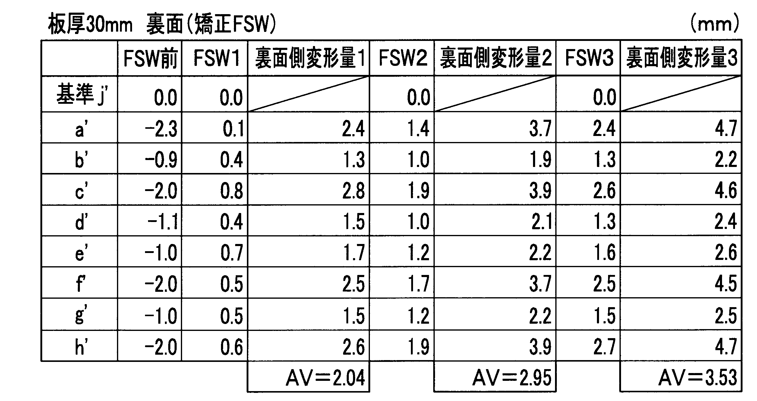
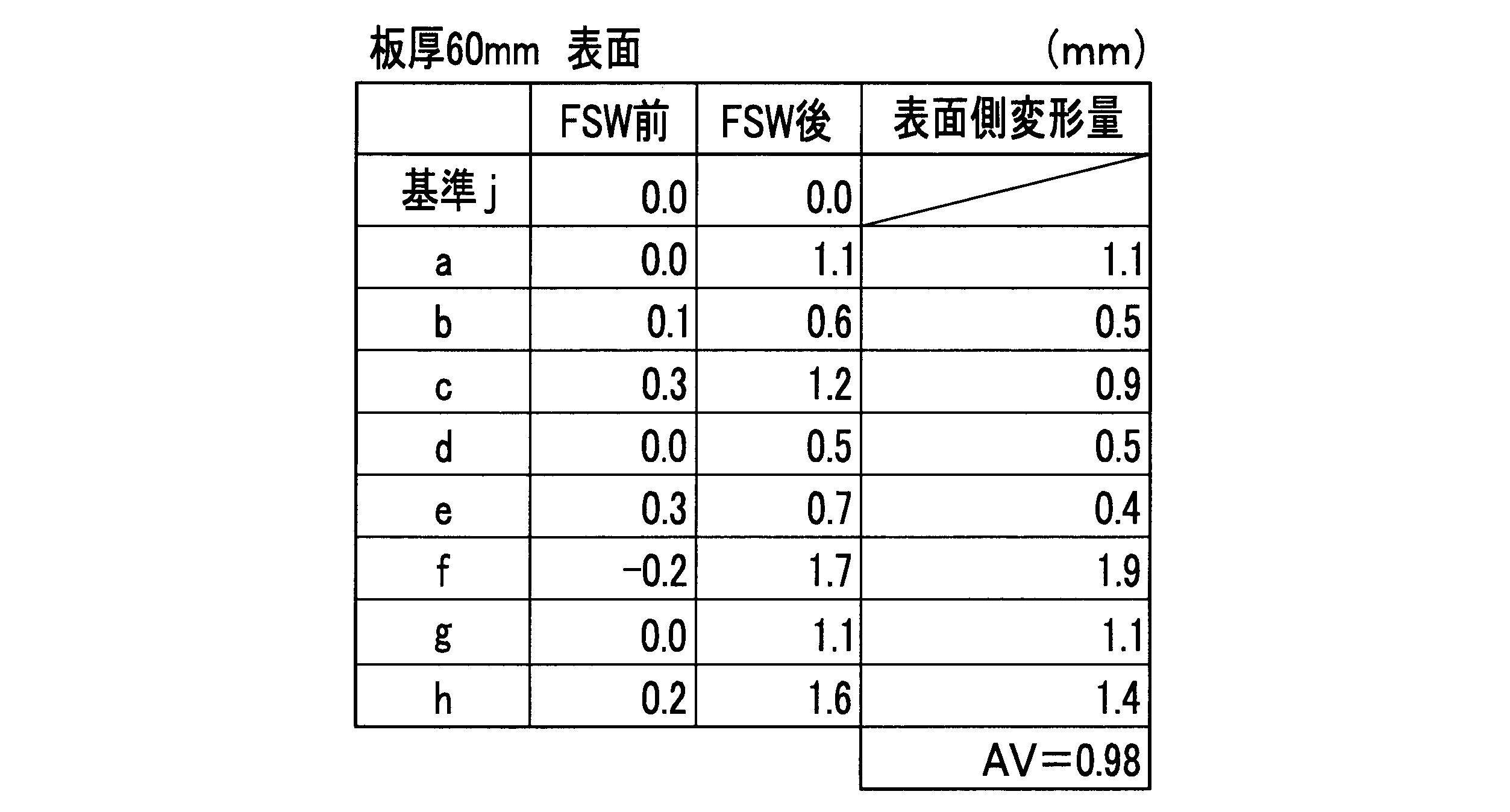

前記した変形例に係る本接合用回転ツールKの各要素の条件(寸法)を表5に示す。表5は、本接合用回転ツールKと同等の構成からなるツールI~ツールIVにおいて、ピン(攪拌ピン)長さ、ピンの最大径、ピンの最小径及びショルダ径の各寸法、各寸法の割合及び回転数・接合速度を示す。表5に記載した各ツールI~ツールIVを用いて、一対のアルミニウム合金(5052アルミニウム合金)に対して摩擦攪拌接合を行い各ツールI~ツールIVにおける各ツールの状況について観察した。
1a 金属部材
1b 金属部材
2 第一タブ材
3 第二タブ材
J1~J3 突合部
A 表面
B 裏面
C 第一側面
D 第二側面
F 仮接合用回転ツール
F1 ショルダ部
F2 攪拌ピン
G 本接合用回転ツール
G1 ショルダ部
G2 攪拌ピン
H 本接合用回転ツール
H1 ショルダ部
H2 攪拌ピン
E 補修用回転ツール
E1 ショルダ部
E2 攪拌ピン
W1,W2 塑性化領域
Claims (14)
- 金属部材同士の突合部に沿って前記金属部材の表面側から本接合用回転ツールを移動させて摩擦攪拌接合を行う第一の本接合工程と、
前記第一の本接合工程の後に、前記突合部に沿って前記金属部材の裏面側から本接合用回転ツールを移動させて摩擦攪拌接合を行う第二の本接合工程と、を含み、
前記第二の本接合工程における前記金属部材への入熱量を、前記第一の本接合工程における前記金属部材への入熱量よりも少なく設定することを特徴とする接合方法。 - 前記第二の本接合工程で使用する本接合用回転ツールは、前記第一の本接合工程で使用する本接合用回転ツールよりも小さいことを特徴とする請求の範囲第1項に記載の接合方法。
- 前記第二の本接合工程では、前記第一の本接合工程における前記本接合用回転ツールの送り速度よりも速い送り速度で摩擦攪拌接合を行うことを特徴とする請求の範囲第1項に記載の接合方法。
- 前記第二の本接合工程の後に、前記金属部材の表面側又は裏面側から摩擦攪拌を行う矯正工程を行うことを特徴とする請求の範囲第1項に記載の接合方法。
- 前記第二の本接合工程では、前記第一の本接合工程で形成された塑性化領域に前記本接合用回転ツールの攪拌ピンを入り込ませつつ摩擦攪拌接合を行うことを特徴とする請求の範囲第1項に記載の接合方法。
- 前記金属部材を固定治具によってテーブルに固定した状態で前記第一の本接合工程及び前記第二の本接合工程を行うことを特徴とする請求の範囲第1項に記載の接合方法。
- 前記本接合用回転ツールは、
前記金属部材よりも硬質の金属からなるショルダ部と、
前記ショルダ部の下端面の中央に突設され先細りの円錐台状に形成された攪拌ピンと、
前記攪拌ピンの外周面に螺旋状に刻設された攪拌翼と、を有し、
前記攪拌ピンの最大外径に対する前記攪拌ピンの長さの比を1.33~2.03に設定することを特徴とする請求の範囲第1項に記載の接合方法。 - 前記本接合用回転ツールは、
前記金属部材よりも硬質の金属からなるショルダ部と、
前記ショルダ部の下端面の中央に突設され先細りの円錐台状に形成された攪拌ピンと、
前記攪拌ピンの外周面に螺旋状に刻設された攪拌翼と、を有し、
前記攪拌ピンの最小外径に対する前記攪拌ピンの最大外径の比を2.00~2.67に設定することを特徴とする請求の範囲第1項に記載の接合方法。 - 前記本接合用回転ツールは、
前記金属部材よりも硬質の金属からなるショルダ部と、
前記ショルダ部の下端面の中央に突設され先細りの円錐台状に形成された攪拌ピンと、
前記攪拌ピンの外周面に螺旋状に刻設された攪拌翼と、を有し、
前記攪拌ピンの最大外径に対する前記ショルダ部の外径の比を1.56~2.14に設定することを特徴とする請求の範囲第1項に記載の接合方法。 - 前記ショルダ部の下端面には、前記攪拌ピンの周囲を囲むように、平面視渦巻き状に突設された攪拌用突条体が形成されていることを特徴とする請求の範囲第7項乃至第9項のいずれか一項に記載の接合方法。
- 前記第一の本接合工程を行う前に、前記第一の本接合工程で用いる前記本接合用回転ツールよりも小型の仮接合用回転ツールを用いて、前記突合部に対して前記金属部材の表面側から摩擦攪拌接合を行う仮接合工程を行うことを特徴とする請求の範囲第1項に記載の接合方法。
- 前記第二の本接合工程を行う前に、前記第二の本接合工程で用いる前記本接合用回転ツールよりも小型の仮接合用回転ツールを用いて、前記突合部に対して前記金属部材の裏面側から摩擦攪拌接合を行う仮接合工程を行うことを特徴とする請求の範囲第1項に記載の接合方法。
- 前記第一の本接合工程では、前記金属部材同士の突合部の側方に配置されたタブ材に摩擦攪拌の開始位置又は終了位置を設け、
前記第一の本接合工程の後に、前記第一の本接合工程で形成された塑性化領域のうち少なくとも前記タブ材に隣接する部分に対して前記本接合用回転ツールよりも小型の補修用回転ツールを用いて摩擦攪拌を行う補修工程を行うことを特徴とする請求の範囲第1項に記載の接合方法。 - 前記第二の本接合工程では、前記金属部材同士の突合部の側方に配置されたタブ材に摩擦攪拌の開始位置又は終了位置を設け、
前記第二の本接合工程の後に、前記第二の本接合工程で形成された塑性化領域のうち少なくとも前記タブ材に隣接する部分に対して前記本接合用回転ツールよりも小型の補修用回転ツールを用いて摩擦攪拌を行う補修工程を行うことを特徴とする請求の範囲第1項に記載の接合方法。
Priority Applications (2)
| Application Number | Priority Date | Filing Date | Title |
|---|---|---|---|
| CN201080025068.5A CN102448657B (zh) | 2009-06-01 | 2010-04-15 | 接合方法 |
| KR1020117031279A KR101250708B1 (ko) | 2009-06-01 | 2010-04-15 | 접합 방법 |
Applications Claiming Priority (2)
| Application Number | Priority Date | Filing Date | Title |
|---|---|---|---|
| JP2009131700A JP5381344B2 (ja) | 2009-06-01 | 2009-06-01 | 接合方法 |
| JP2009-131700 | 2009-06-01 |
Publications (1)
| Publication Number | Publication Date |
|---|---|
| WO2010140428A1 true WO2010140428A1 (ja) | 2010-12-09 |
Family
ID=43297570
Family Applications (1)
| Application Number | Title | Priority Date | Filing Date |
|---|---|---|---|
| PCT/JP2010/056775 Ceased WO2010140428A1 (ja) | 2009-06-01 | 2010-04-15 | 接合方法 |
Country Status (5)
| Country | Link |
|---|---|
| JP (1) | JP5381344B2 (ja) |
| KR (1) | KR101250708B1 (ja) |
| CN (2) | CN102448657B (ja) |
| TW (1) | TWI405631B (ja) |
| WO (1) | WO2010140428A1 (ja) |
Families Citing this family (14)
| Publication number | Priority date | Publication date | Assignee | Title |
|---|---|---|---|---|
| JP5957720B2 (ja) * | 2011-08-30 | 2016-07-27 | 日本軽金属株式会社 | 摩擦攪拌接合方法 |
| KR20170002686A (ko) | 2011-08-19 | 2017-01-06 | 니폰게이긴조쿠가부시키가이샤 | 마찰 교반 접합 방법 |
| JP6273821B2 (ja) * | 2013-12-18 | 2018-02-07 | 日本軽金属株式会社 | 接合方法 |
| JP6260327B2 (ja) * | 2014-02-17 | 2018-01-17 | 日本軽金属株式会社 | 接合方法 |
| JP6112133B2 (ja) * | 2015-04-01 | 2017-04-12 | 日本軽金属株式会社 | 摩擦攪拌接合方法 |
| JP6283328B2 (ja) * | 2015-04-01 | 2018-02-21 | 日本軽金属株式会社 | 摩擦攪拌接合方法 |
| JP6112175B2 (ja) * | 2015-10-27 | 2017-04-12 | 日本軽金属株式会社 | 摩擦攪拌接合方法 |
| CN106392298A (zh) * | 2016-10-17 | 2017-02-15 | 南昌航空大学 | 一种不等厚度的铝和钢异种金属搅拌摩擦焊接方法 |
| JP2018134668A (ja) * | 2017-02-22 | 2018-08-30 | 日本軽金属株式会社 | 接合方法 |
| JP6964840B2 (ja) * | 2019-05-16 | 2021-11-10 | 三菱電機株式会社 | 摩擦攪拌接合用回転工具及び摩擦攪拌接合方法 |
| JP2021079422A (ja) * | 2019-11-21 | 2021-05-27 | 日本軽金属株式会社 | 液冷ジャケットの製造方法 |
| CN111001678A (zh) * | 2019-12-10 | 2020-04-14 | 昆山万洲特种焊接有限公司 | 一种基于搅拌摩擦焊接的矫形方法 |
| CN111230188A (zh) * | 2020-01-20 | 2020-06-05 | 哈尔滨工业大学 | 一种用于搅拌摩擦制造的搅拌头及应用其制备水冷通道的方法 |
| JP7452496B2 (ja) | 2021-06-07 | 2024-03-19 | 日本軽金属株式会社 | 接合体の製造方法および接合装置 |
Citations (6)
| Publication number | Priority date | Publication date | Assignee | Title |
|---|---|---|---|---|
| JP2000334577A (ja) * | 1999-05-25 | 2000-12-05 | Kawasaki Heavy Ind Ltd | 接合装置及び接合方法 |
| JP2001269780A (ja) * | 2000-03-27 | 2001-10-02 | Ishikawajima Harima Heavy Ind Co Ltd | 低温液化ガス用容器 |
| JP2003181653A (ja) * | 2001-12-13 | 2003-07-02 | Nippon Light Metal Co Ltd | 化粧面を有する部材の摩擦攪拌接合方法並びに構造体及びその製造方法 |
| JP2003211326A (ja) * | 2002-01-16 | 2003-07-29 | Hitachi Ltd | 金属部品の製造方法および金属部品 |
| JP2005177844A (ja) * | 2003-12-22 | 2005-07-07 | Kawasaki Heavy Ind Ltd | 摩擦撹拌接合方法 |
| JP2009101401A (ja) * | 2007-10-25 | 2009-05-14 | Nippon Light Metal Co Ltd | 接合方法 |
Family Cites Families (7)
| Publication number | Priority date | Publication date | Assignee | Title |
|---|---|---|---|---|
| JP3307330B2 (ja) * | 1998-06-01 | 2002-07-24 | 日本軽金属株式会社 | 厚肉の被接合材の摩擦攪拌接合方法及び接合構造 |
| JP4273846B2 (ja) * | 2003-06-06 | 2009-06-03 | 日本軽金属株式会社 | 厚肉被接合材の接合方法及び接合構造 |
| JP4281510B2 (ja) * | 2003-10-30 | 2009-06-17 | 日本軽金属株式会社 | 真空容器の製造方法 |
| CN102267007B (zh) * | 2006-10-02 | 2015-11-25 | 日本轻金属株式会社 | 接合方法 |
| JP5023909B2 (ja) * | 2007-09-18 | 2012-09-12 | 日本軽金属株式会社 | 接合方法 |
| CN101214579A (zh) * | 2008-01-21 | 2008-07-09 | 侯贤忠 | 一种加热搅拌焊接方法及搅拌头 |
| CN101559537A (zh) * | 2009-06-02 | 2009-10-21 | 湘潭电机股份有限公司 | 双轴肩搅拌摩擦焊接方法及设备 |
-
2009
- 2009-06-01 JP JP2009131700A patent/JP5381344B2/ja not_active Expired - Fee Related
-
2010
- 2010-04-15 WO PCT/JP2010/056775 patent/WO2010140428A1/ja not_active Ceased
- 2010-04-15 KR KR1020117031279A patent/KR101250708B1/ko not_active Expired - Fee Related
- 2010-04-15 CN CN201080025068.5A patent/CN102448657B/zh not_active Expired - Fee Related
- 2010-04-15 CN CN201410050339.2A patent/CN103817428B/zh not_active Expired - Fee Related
- 2010-05-27 TW TW099116960A patent/TWI405631B/zh not_active IP Right Cessation
Patent Citations (6)
| Publication number | Priority date | Publication date | Assignee | Title |
|---|---|---|---|---|
| JP2000334577A (ja) * | 1999-05-25 | 2000-12-05 | Kawasaki Heavy Ind Ltd | 接合装置及び接合方法 |
| JP2001269780A (ja) * | 2000-03-27 | 2001-10-02 | Ishikawajima Harima Heavy Ind Co Ltd | 低温液化ガス用容器 |
| JP2003181653A (ja) * | 2001-12-13 | 2003-07-02 | Nippon Light Metal Co Ltd | 化粧面を有する部材の摩擦攪拌接合方法並びに構造体及びその製造方法 |
| JP2003211326A (ja) * | 2002-01-16 | 2003-07-29 | Hitachi Ltd | 金属部品の製造方法および金属部品 |
| JP2005177844A (ja) * | 2003-12-22 | 2005-07-07 | Kawasaki Heavy Ind Ltd | 摩擦撹拌接合方法 |
| JP2009101401A (ja) * | 2007-10-25 | 2009-05-14 | Nippon Light Metal Co Ltd | 接合方法 |
Also Published As
| Publication number | Publication date |
|---|---|
| KR20120024868A (ko) | 2012-03-14 |
| CN103817428A (zh) | 2014-05-28 |
| CN103817428B (zh) | 2016-08-17 |
| CN102448657B (zh) | 2014-10-29 |
| TWI405631B (zh) | 2013-08-21 |
| JP5381344B2 (ja) | 2014-01-08 |
| JP2010274320A (ja) | 2010-12-09 |
| TW201043370A (en) | 2010-12-16 |
| KR101250708B1 (ko) | 2013-04-03 |
| CN102448657A (zh) | 2012-05-09 |
Similar Documents
| Publication | Publication Date | Title |
|---|---|---|
| JP5381344B2 (ja) | 接合方法 | |
| JP5790828B2 (ja) | 接合方法 | |
| JP5915802B2 (ja) | 摩擦攪拌接合方法 | |
| JP2015120204A (ja) | 摩擦攪拌接合方法 | |
| JP5459416B2 (ja) | 接合方法 | |
| JP5092333B2 (ja) | 接合方法 | |
| JP5641117B2 (ja) | 接合方法 | |
| JP5508375B2 (ja) | 接合方法 | |
| JP6273821B2 (ja) | 接合方法 | |
| JP5082364B2 (ja) | 接合方法 | |
| JP4844329B2 (ja) | 接合方法 | |
| JP4957161B2 (ja) | 摩擦攪拌方法 | |
| JP4957160B2 (ja) | 接合方法 | |
| JP5338884B2 (ja) | 接合方法 | |
| JP4935282B2 (ja) | 摩擦攪拌方法 | |
| JP4844328B2 (ja) | 接合方法 |
Legal Events
| Date | Code | Title | Description |
|---|---|---|---|
| WWE | Wipo information: entry into national phase |
Ref document number: 201080025068.5 Country of ref document: CN |
|
| 121 | Ep: the epo has been informed by wipo that ep was designated in this application |
Ref document number: 10783214 Country of ref document: EP Kind code of ref document: A1 |
|
| NENP | Non-entry into the national phase |
Ref country code: DE |
|
| ENP | Entry into the national phase |
Ref document number: 20117031279 Country of ref document: KR Kind code of ref document: A |
|
| 122 | Ep: pct application non-entry in european phase |
Ref document number: 10783214 Country of ref document: EP Kind code of ref document: A1 |