WO2010140305A1 - 動力発生源制御装置 - Google Patents
動力発生源制御装置 Download PDFInfo
- Publication number
- WO2010140305A1 WO2010140305A1 PCT/JP2010/003297 JP2010003297W WO2010140305A1 WO 2010140305 A1 WO2010140305 A1 WO 2010140305A1 JP 2010003297 W JP2010003297 W JP 2010003297W WO 2010140305 A1 WO2010140305 A1 WO 2010140305A1
- Authority
- WO
- WIPO (PCT)
- Prior art keywords
- power
- vehicle
- travel
- destination
- mode
- Prior art date
- Legal status (The legal status is an assumption and is not a legal conclusion. Google has not performed a legal analysis and makes no representation as to the accuracy of the status listed.)
- Ceased
Links
Images


Classifications
-
- B—PERFORMING OPERATIONS; TRANSPORTING
- B60—VEHICLES IN GENERAL
- B60W—CONJOINT CONTROL OF VEHICLE SUB-UNITS OF DIFFERENT TYPE OR DIFFERENT FUNCTION; CONTROL SYSTEMS SPECIALLY ADAPTED FOR HYBRID VEHICLES; ROAD VEHICLE DRIVE CONTROL SYSTEMS FOR PURPOSES NOT RELATED TO THE CONTROL OF A PARTICULAR SUB-UNIT
- B60W50/00—Details of control systems for road vehicle drive control not related to the control of a particular sub-unit, e.g. process diagnostic or vehicle driver interfaces
- B60W50/0097—Predicting future conditions
-
- B—PERFORMING OPERATIONS; TRANSPORTING
- B60—VEHICLES IN GENERAL
- B60W—CONJOINT CONTROL OF VEHICLE SUB-UNITS OF DIFFERENT TYPE OR DIFFERENT FUNCTION; CONTROL SYSTEMS SPECIALLY ADAPTED FOR HYBRID VEHICLES; ROAD VEHICLE DRIVE CONTROL SYSTEMS FOR PURPOSES NOT RELATED TO THE CONTROL OF A PARTICULAR SUB-UNIT
- B60W20/00—Control systems specially adapted for hybrid vehicles
- B60W20/10—Controlling the power contribution of each of the prime movers to meet required power demand
-
- B—PERFORMING OPERATIONS; TRANSPORTING
- B60—VEHICLES IN GENERAL
- B60K—ARRANGEMENT OR MOUNTING OF PROPULSION UNITS OR OF TRANSMISSIONS IN VEHICLES; ARRANGEMENT OR MOUNTING OF PLURAL DIVERSE PRIME-MOVERS IN VEHICLES; AUXILIARY DRIVES FOR VEHICLES; INSTRUMENTATION OR DASHBOARDS FOR VEHICLES; ARRANGEMENTS IN CONNECTION WITH COOLING, AIR INTAKE, GAS EXHAUST OR FUEL SUPPLY OF PROPULSION UNITS IN VEHICLES
- B60K6/00—Arrangement or mounting of plural diverse prime-movers for mutual or common propulsion, e.g. hybrid propulsion systems comprising electric motors and internal combustion engines
- B60K6/20—Arrangement or mounting of plural diverse prime-movers for mutual or common propulsion, e.g. hybrid propulsion systems comprising electric motors and internal combustion engines the prime-movers consisting of electric motors and internal combustion engines, e.g. HEVs
- B60K6/42—Arrangement or mounting of plural diverse prime-movers for mutual or common propulsion, e.g. hybrid propulsion systems comprising electric motors and internal combustion engines the prime-movers consisting of electric motors and internal combustion engines, e.g. HEVs characterised by the architecture of the hybrid electric vehicle
- B60K6/44—Series-parallel type
-
- B—PERFORMING OPERATIONS; TRANSPORTING
- B60—VEHICLES IN GENERAL
- B60L—PROPULSION OF ELECTRICALLY-PROPELLED VEHICLES; SUPPLYING ELECTRIC POWER FOR AUXILIARY EQUIPMENT OF ELECTRICALLY-PROPELLED VEHICLES; ELECTRODYNAMIC BRAKE SYSTEMS FOR VEHICLES IN GENERAL; MAGNETIC SUSPENSION OR LEVITATION FOR VEHICLES; MONITORING OPERATING VARIABLES OF ELECTRICALLY-PROPELLED VEHICLES; ELECTRIC SAFETY DEVICES FOR ELECTRICALLY-PROPELLED VEHICLES
- B60L50/00—Electric propulsion with power supplied within the vehicle
- B60L50/10—Electric propulsion with power supplied within the vehicle using propulsion power supplied by engine-driven generators, e.g. generators driven by combustion engines
- B60L50/16—Electric propulsion with power supplied within the vehicle using propulsion power supplied by engine-driven generators, e.g. generators driven by combustion engines with provision for separate direct mechanical propulsion
-
- B—PERFORMING OPERATIONS; TRANSPORTING
- B60—VEHICLES IN GENERAL
- B60L—PROPULSION OF ELECTRICALLY-PROPELLED VEHICLES; SUPPLYING ELECTRIC POWER FOR AUXILIARY EQUIPMENT OF ELECTRICALLY-PROPELLED VEHICLES; ELECTRODYNAMIC BRAKE SYSTEMS FOR VEHICLES IN GENERAL; MAGNETIC SUSPENSION OR LEVITATION FOR VEHICLES; MONITORING OPERATING VARIABLES OF ELECTRICALLY-PROPELLED VEHICLES; ELECTRIC SAFETY DEVICES FOR ELECTRICALLY-PROPELLED VEHICLES
- B60L50/00—Electric propulsion with power supplied within the vehicle
- B60L50/50—Electric propulsion with power supplied within the vehicle using propulsion power supplied by batteries or fuel cells
- B60L50/60—Electric propulsion with power supplied within the vehicle using propulsion power supplied by batteries or fuel cells using power supplied by batteries
- B60L50/61—Electric propulsion with power supplied within the vehicle using propulsion power supplied by batteries or fuel cells using power supplied by batteries by batteries charged by engine-driven generators, e.g. series hybrid electric vehicles
-
- B—PERFORMING OPERATIONS; TRANSPORTING
- B60—VEHICLES IN GENERAL
- B60W—CONJOINT CONTROL OF VEHICLE SUB-UNITS OF DIFFERENT TYPE OR DIFFERENT FUNCTION; CONTROL SYSTEMS SPECIALLY ADAPTED FOR HYBRID VEHICLES; ROAD VEHICLE DRIVE CONTROL SYSTEMS FOR PURPOSES NOT RELATED TO THE CONTROL OF A PARTICULAR SUB-UNIT
- B60W10/00—Conjoint control of vehicle sub-units of different type or different function
- B60W10/04—Conjoint control of vehicle sub-units of different type or different function including control of propulsion units
- B60W10/06—Conjoint control of vehicle sub-units of different type or different function including control of propulsion units including control of combustion engines
-
- B—PERFORMING OPERATIONS; TRANSPORTING
- B60—VEHICLES IN GENERAL
- B60W—CONJOINT CONTROL OF VEHICLE SUB-UNITS OF DIFFERENT TYPE OR DIFFERENT FUNCTION; CONTROL SYSTEMS SPECIALLY ADAPTED FOR HYBRID VEHICLES; ROAD VEHICLE DRIVE CONTROL SYSTEMS FOR PURPOSES NOT RELATED TO THE CONTROL OF A PARTICULAR SUB-UNIT
- B60W10/00—Conjoint control of vehicle sub-units of different type or different function
- B60W10/04—Conjoint control of vehicle sub-units of different type or different function including control of propulsion units
- B60W10/08—Conjoint control of vehicle sub-units of different type or different function including control of propulsion units including control of electric propulsion units, e.g. motors or generators
-
- B—PERFORMING OPERATIONS; TRANSPORTING
- B60—VEHICLES IN GENERAL
- B60W—CONJOINT CONTROL OF VEHICLE SUB-UNITS OF DIFFERENT TYPE OR DIFFERENT FUNCTION; CONTROL SYSTEMS SPECIALLY ADAPTED FOR HYBRID VEHICLES; ROAD VEHICLE DRIVE CONTROL SYSTEMS FOR PURPOSES NOT RELATED TO THE CONTROL OF A PARTICULAR SUB-UNIT
- B60W20/00—Control systems specially adapted for hybrid vehicles
-
- B—PERFORMING OPERATIONS; TRANSPORTING
- B60—VEHICLES IN GENERAL
- B60W—CONJOINT CONTROL OF VEHICLE SUB-UNITS OF DIFFERENT TYPE OR DIFFERENT FUNCTION; CONTROL SYSTEMS SPECIALLY ADAPTED FOR HYBRID VEHICLES; ROAD VEHICLE DRIVE CONTROL SYSTEMS FOR PURPOSES NOT RELATED TO THE CONTROL OF A PARTICULAR SUB-UNIT
- B60W20/00—Control systems specially adapted for hybrid vehicles
- B60W20/10—Controlling the power contribution of each of the prime movers to meet required power demand
- B60W20/12—Controlling the power contribution of each of the prime movers to meet required power demand using control strategies taking into account route information
-
- F—MECHANICAL ENGINEERING; LIGHTING; HEATING; WEAPONS; BLASTING
- F02—COMBUSTION ENGINES; HOT-GAS OR COMBUSTION-PRODUCT ENGINE PLANTS
- F02D—CONTROLLING COMBUSTION ENGINES
- F02D29/00—Controlling engines, such controlling being peculiar to the devices driven thereby, the devices being other than parts or accessories essential to engine operation, e.g. controlling of engines by signals external thereto
- F02D29/02—Controlling engines, such controlling being peculiar to the devices driven thereby, the devices being other than parts or accessories essential to engine operation, e.g. controlling of engines by signals external thereto peculiar to engines driving vehicles; peculiar to engines driving variable pitch propellers
-
- B—PERFORMING OPERATIONS; TRANSPORTING
- B60—VEHICLES IN GENERAL
- B60W—CONJOINT CONTROL OF VEHICLE SUB-UNITS OF DIFFERENT TYPE OR DIFFERENT FUNCTION; CONTROL SYSTEMS SPECIALLY ADAPTED FOR HYBRID VEHICLES; ROAD VEHICLE DRIVE CONTROL SYSTEMS FOR PURPOSES NOT RELATED TO THE CONTROL OF A PARTICULAR SUB-UNIT
- B60W2510/00—Input parameters relating to a particular sub-units
- B60W2510/24—Energy storage means
- B60W2510/242—Energy storage means for electrical energy
- B60W2510/244—Charge state
-
- Y—GENERAL TAGGING OF NEW TECHNOLOGICAL DEVELOPMENTS; GENERAL TAGGING OF CROSS-SECTIONAL TECHNOLOGIES SPANNING OVER SEVERAL SECTIONS OF THE IPC; TECHNICAL SUBJECTS COVERED BY FORMER USPC CROSS-REFERENCE ART COLLECTIONS [XRACs] AND DIGESTS
- Y02—TECHNOLOGIES OR APPLICATIONS FOR MITIGATION OR ADAPTATION AGAINST CLIMATE CHANGE
- Y02T—CLIMATE CHANGE MITIGATION TECHNOLOGIES RELATED TO TRANSPORTATION
- Y02T10/00—Road transport of goods or passengers
- Y02T10/60—Other road transportation technologies with climate change mitigation effect
- Y02T10/62—Hybrid vehicles
-
- Y—GENERAL TAGGING OF NEW TECHNOLOGICAL DEVELOPMENTS; GENERAL TAGGING OF CROSS-SECTIONAL TECHNOLOGIES SPANNING OVER SEVERAL SECTIONS OF THE IPC; TECHNICAL SUBJECTS COVERED BY FORMER USPC CROSS-REFERENCE ART COLLECTIONS [XRACs] AND DIGESTS
- Y02—TECHNOLOGIES OR APPLICATIONS FOR MITIGATION OR ADAPTATION AGAINST CLIMATE CHANGE
- Y02T—CLIMATE CHANGE MITIGATION TECHNOLOGIES RELATED TO TRANSPORTATION
- Y02T10/00—Road transport of goods or passengers
- Y02T10/60—Other road transportation technologies with climate change mitigation effect
- Y02T10/70—Energy storage systems for electromobility, e.g. batteries
-
- Y—GENERAL TAGGING OF NEW TECHNOLOGICAL DEVELOPMENTS; GENERAL TAGGING OF CROSS-SECTIONAL TECHNOLOGIES SPANNING OVER SEVERAL SECTIONS OF THE IPC; TECHNICAL SUBJECTS COVERED BY FORMER USPC CROSS-REFERENCE ART COLLECTIONS [XRACs] AND DIGESTS
- Y02—TECHNOLOGIES OR APPLICATIONS FOR MITIGATION OR ADAPTATION AGAINST CLIMATE CHANGE
- Y02T—CLIMATE CHANGE MITIGATION TECHNOLOGIES RELATED TO TRANSPORTATION
- Y02T10/00—Road transport of goods or passengers
- Y02T10/60—Other road transportation technologies with climate change mitigation effect
- Y02T10/7072—Electromobility specific charging systems or methods for batteries, ultracapacitors, supercapacitors or double-layer capacitors
Definitions
- the present invention relates to a power generation source control device that is used in a hybrid vehicle and controls a power generation source.
- hybrid vehicle including an internal combustion engine and a rotating electric machine as a power generation source that generates power for driving the drive shaft of the vehicle.
- This conventional device predicts a route travel pattern based on road data, and sets engine and motor operation schedules based on the predicted travel pattern. Furthermore, the set operation schedule can be reset.
- the reason why the resetting is possible is that it is considered that the vehicle cannot travel according to the set driving schedule due to an unexpected traffic jam or the driving condition of the driver that day.
- the operation schedule is reset.
- the driving schedule before resetting was not appropriate. That is, the driving schedule before resetting was not a sufficiently fuel-efficient driving.
- the operation schedule after resetting is not always an appropriate schedule. That is, even after resetting, traveling with sufficiently high fuel efficiency is not always performed.
- a plan may be set in which all the electric driving is performed to the destination. Therefore, if the warm-up control of the internal combustion engine, for example, fuel increase, is always performed without considering whether or not the internal combustion engine is used as a power generation source, the fuel is wasted and the practical fuel consumption is reduced. I will let you.
- an object of the present invention is to provide a power generation source control device capable of improving the practical fuel consumption.
- the travel mode is set to the electric travel mode or the internal combustion engine drive mode based on the comparison between the drive power and the power threshold that are determined sequentially, rather than planning the travel mode in advance. Switch between. Therefore, unlike the case where the travel mode is planned in advance, there can be no deviation between the driving power assumed at the time of planning and the driving power actually generated, so that the fuel consumption can be reliably improved.
- the power threshold used for selecting the travel mode is set to a low threshold while it is determined that the vehicle cannot reach the destination if the power travel mode is maintained. In a state where the power threshold is set to the low threshold, driving power exceeding the low threshold is often required in the high load section, and thus the vehicle is often driven in the internal combustion engine drive mode. In other words, the amount of charge suddenly decreases when traveling in the electric travel mode, and it is suppressed to select the electric travel mode in a high load section where the efficiency is worse than when traveling on a flat road in the electric travel mode. Practical fuel consumption is improved.
- the vehicle at the time of departure, it is determined whether or not the vehicle can run to the destination while keeping the electric travel mode.
- the internal combustion engine does not need to be driven, and thus the warm-up control of the internal combustion engine is not performed. Therefore, the fuel efficiency required for warm-up control of the internal combustion engine can be saved and the practical fuel efficiency can be improved.
- FIG. 1 is a block diagram showing an embodiment of a power generation source driving device of the present invention mounted on a hybrid vehicle. It is a flowchart which shows the warm-up necessity determination process implemented at the time of a vehicle departure in this embodiment. It is a flowchart which shows the threshold value setting process which sets the threshold value used for switching determination of driving mode in this embodiment.
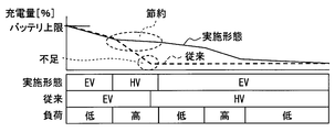
- 4A and 4B are diagrams showing the relationship between the power threshold value set in the threshold value setting process of FIG. 3, the traveling power, and the traveling mode, along with the change in SOC. It is a figure which shows notionally the change of the fuel consumption with respect to load about this embodiment and a conventional apparatus.
- the hybrid vehicle 1 includes an engine 2 and a motor generator (MG) 3 as power generation sources.
- the engine 2 is an internal combustion engine that uses gasoline or light oil as fuel.
- the output shaft of the engine 2 is connected to the axle of the drive wheel via a planetary gear device, a reduction gear, and a differential gear (not shown).
- the motor generator 3 is connected to an inverter 4, and the inverter 4 is electrically connected to a battery 6.
- the number of motor generators 3 is not limited to one and may be two.
- the motor generator 3 functions as a motor to generate power when electric power from the battery 6 is supplied. On the other hand, when the rotation of the wheel or the engine 2 is transmitted, it functions as a generator and generates electric power. Electric power generated by the motor generator 3 functioning as a generator is stored in the battery 6.
- the battery 6 corresponds to a power storage device, and for example, a nickel hydride secondary battery is used.
- the charge amount monitoring unit 8 detects an input / output current with respect to the battery 6 by a current sensor (not shown), sequentially monitors the voltage of the battery 6, and sequentially calculates the storage state (SOC) of the battery 6 based on them. Then, a signal representing the SOC is sequentially supplied to the hybrid travel (HV) control unit 10 and the navigation unit 30.
- a current sensor not shown
- SOC storage state
- HV hybrid travel
- the charge amount monitoring unit 8 sequentially calculates the maximum power amount that can be charged by the battery 6 and the maximum power amount that can be discharged from the SOC and the rated capacity of the battery 6.
- the chargeable maximum power amount and the dischargeable maximum power amount are also transmitted to the HV control unit 10.
- the HV controller 10 is supplied with a vehicle speed signal SSp representing the vehicle speed and an accelerator opening signal Acc representing the accelerator opening.
- the charge amount monitoring unit 8, the MG control unit 12, the engine control unit 14, and the navigation unit 30 perform transmission / reception of signals with each other, and execute predetermined calculation processing based on various supplied signals.
- the calculation process includes a calculation process of the drive power request value Pr required by the vehicle 1.
- This drive power request value Pr is calculated based on the accelerator opening and the vehicle speed. Specifically, the required drive torque is set from the accelerator opening using a required drive torque determination map stored in advance. Note that the transmission gear shift position may be used in addition to the accelerator opening for determining the required drive torque.
- the rotational speed of the axle is calculated based on the vehicle speed, and the drive power request value Pr is calculated by multiplying the rotation speed by the required drive torque.
- the calculation process of the drive power request value Pr corresponds to drive power determination means.
- the HV control unit 10 compares the drive power request value Pr with a predetermined power threshold value Pt, and based on the comparison result, whether to travel in the electric (EV) travel mode or the HV travel mode.
- the traveling mode switching process for switching between is sequentially performed during traveling.
- the EV travel mode corresponds to an electric travel mode in which the engine 2 is stopped, electric power is supplied from the battery 6 and the vehicle 1 is traveled using only the motor generator 3 as a power generation source.
- the HV travel mode corresponds to an engine drive mode that uses the engine 2 as a power generation source. In the HV traveling mode, only the engine 2 may be used as a power generation source, or two types of power generation sources, that is, the engine 2 and the motor generator 3 may be used. When the SOC reaches the lower limit of use, the HV travel mode is selected regardless of the magnitude of the drive power request value Pr because the amount of power stored in the battery 6 is insufficient.
- the HV control unit 10 When the EV travel mode is selected, the HV control unit 10 outputs a signal instructing to generate the drive power request value Pr (or torque corresponding thereto) to the MG control unit 12. On the other hand, when the HV traveling mode is selected, the HV control unit 10 determines the driving power (or torque) generated by the engine 2 and the driving power (or torque) generated by the motor generator 3 based on the driving power request value Pr. Are output to the engine control unit 14 and the MG control unit 12, respectively. As described above, the HV control unit 10 uses the predetermined power threshold value Pt to determine whether to travel in the EV traveling mode or in the HV traveling mode.
- the power threshold value Pt is not constant, and is set by switching one of a low threshold value (here 7.5 kw) and a high threshold value (here 30 kw) while the vehicle is running.
- a low threshold value here 7.5 kw
- a high threshold value here 30 kw
- the HV control unit 10 performs a warm-up necessity determination process for determining whether or not to perform the warm-up control of the engine 2 at the time of departure. This process will be described in detail later with reference to FIG.
- the navigation unit 30 includes a position detection unit 32, a control unit 34, a map database (DB) 36, and a learning database (DB) 38.
- the position detection unit 32 includes at least one device generally used for vehicle position detection, such as a GPS receiver, and sequentially detects the current position of the vehicle 1 using the device.
- the control unit 34 displays a road map stored in the map DB 36 and a map display process for displaying a road map around the current position based on the current position sequentially detected by the position detection unit 32, and a route from the departure point to the destination.
- Normal processing of the navigation device such as route search processing for searching for, is performed, and traveling power related value learning processing is sequentially performed during traveling.
- This learning process is a process of sequentially storing the driving power related value for determining the driving power in association with the position and storing it in the learning DB 38.
- the vehicle speed and the accelerator opening are stored as the driving power related value.
- the position may be a single point or a section. Various sections can be set here.
- a predetermined distance a section obtained by dividing a route from the start to the stop, between the intersections, and the route to the destination into a predetermined number can be used.
- the vehicle speed and the accelerator opening store the average value of the section. This learning process corresponds to the travel power related value storage means.
- a charger 40 corresponding to external power input means is connected to a charging connector 42 via a charging cable 41.
- the charger 40 acquires power from a power supply facility installed at the charging station or home, and uses the acquired power.
- the battery 6 is supplied.
- the amount of power that the charger 40 supplies to the battery 6, that is, the amount of charge, is controlled by the charger controller 44.
- the charger control unit 44 controls the amount of charge of the charger 40 until the battery 6 reaches a predetermined voltage or charges the battery 6 with a predetermined amount of current.
- FIG. 2 shows a flowchart of the warm-up necessity determination process performed by the vehicle 1 at the time of departure.
- the time of departure is from when the power position of the vehicle 1 is turned off to the accessory or on until the vehicle starts running.
- the processing shown in FIG. 2 is performed by the HV control unit 10, but some processing may be performed by the control unit 34 of the navigation unit 30.
- step S1 the travel power related value of the route from the current value (that is, the departure point) to the destination, that is, the vehicle speed and the accelerator opening are acquired from the learning DB 38, and the travel distance to the destination is acquired. Further, the current SOC is acquired from the charge monitoring unit 8.
- the destination here is the destination when the destination is set by the vehicle occupant, but is not limited thereto, and may be set automatically from the current position or past travel history.
- the amount of power that can be used for EV travel (usable power amount Wa) [kWh] and the amount of power required for traveling to the destination in the EV travel mode are obtained from the information acquired in step S1.
- An estimated required power amount Wr that is an estimated value is calculated.
- the usable electric energy Wa is calculated based on a difference between the current SOC acquired in step S1 and a preset SOC lower limit value.
- the estimated required power amount Wr is calculated by first calculating the drive power Pr [kW] required when traveling in the EV travel mode on the route to the destination from the travel power related value acquired in step S1. From the drive power Pr [kW], the travel energy [kWh] required for traveling on the route to the destination is calculated for each predetermined section.
- step S3 it is determined whether or not the usable power amount Wa calculated in step S2 is larger than the estimated required power amount Wr calculated in step S2 as determination means. If this determination is affirmative (YES), that is, if the available power amount Wa is greater than the estimated required power amount Wr, the process proceeds to step S4, and it is determined not to perform engine warm-up control. If the available power amount Wa is larger than the estimated required power amount Wr, the EV 2 can run to the destination in the EV travel mode. Therefore, when the EV travel mode can run to the destination, the engine 2 needs to be warmed up. Absent.
- step S3 determines whether the available power amount Wa is less than or equal to the estimated required power amount Wr. If the available power amount Wa is less than or equal to the estimated required power amount Wr, it is necessary to travel with the engine 2, the process proceeds to step S5.
- step S5 it is determined to perform known warm-up control of the engine 2. For example, the engine 2 is forcibly driven before the vehicle starts running, and the fuel is increased to warm up. Alternatively, the engine may be warmed up before starting the first engine drive (for example, entering the HV section) after the vehicle starts running.
- step S11 it is determined whether or not the next section has been entered. If it is determined that it is not in the next section, a negative determination is made in step S11, and the process proceeds to step S17. If it is determined in step S17 that the vehicle has not arrived at the destination, the determination in step S11 is performed again. Therefore, step S11 determines whether or not the next section has been reached with respect to the section that was running at the time of the previous execution of step S11.
- the section here can be variously set similarly to the section in the learning process.
- the section here may be the same section as the section in the learning process, or may be a section different from the section in the learning process.
- step S11 If step S11 is affirmative, the process proceeds to step S12.
- step S12 as in the process of step S1 of FIG. 2, the travel power related values (ie, vehicle speed and accelerator opening) of the route from the current position to the destination, the remaining distance to the destination, and the current SOC are calculated. get.
- step S13 the estimated required power amount Wr and the usable power amount Wa are calculated in the same manner as in step S2 of FIG.
- step S14 which is a process corresponding to the determination means, is executed.
- step S13 it is determined whether or not the available power amount Wa calculated in step S13 is greater than or equal to the estimated required power amount Wr calculated in step S13. If this determination is affirmative, that is, if the available power amount Wa is equal to or greater than the estimated required power amount Wr, the process proceeds to step S15, and a load higher than 30 kw is set to a high load by setting the power threshold Pt to 30 kw It is determined to be a section.
- the power threshold value Pt is set to 30 kw
- the drive power request value Pr does not exceed the power threshold value Pt unless the load is considerably high.
- the EV traveling mode is almost selected. Therefore, when the usable power amount Wa is equal to or greater than the estimated required power amount Wr, the vehicle travels to the destination in principle in the EV travel mode.
- step S16 the power threshold Wr is set to 7.5 kw so that a load higher than 7.5 kw is determined as a high load section.
- the power threshold value Pt is set to 7.5 kw in this way, the drive power request value Pr exceeds the power threshold value Wt even with a relatively low load. As a result, the HV traveling mode is selected in the high load section.
- step S15 or step S16 the process proceeds to step S17 to determine whether or not the destination has been reached. If the destination has been reached, the process is terminated. If the destination has not been reached, the process returns to step S11 to continue the process.
- FIG. 4A and 4 (B) show the relationship between the power threshold Pt set in step S15 or S16 in FIG. 3, the travel power (drive power request value Pr), and the travel mode, along with the change in SOC. Show. Specifically, FIG. 4A shows a case where the available power amount Wa is smaller than the estimated required power amount Wr (S14 is NO), and FIG. 4B shows that the available power amount Wa is the estimated required power amount Wr. This is the case (S14 is YES).
- the horizontal axis of each figure is time or distance.
- the vehicle 1 of the present embodiment has improved fuel efficiency compared to a conventional hybrid vehicle.
- the conventional hybrid vehicle here travels first in the EV travel mode until the SOC reaches the lower limit value of use regardless of the magnitude of the drive power request value Pr, and the SOC reaches the lower limit value of use. After that, traveling control is performed to travel in the HV traveling mode.
- the conventional hybrid vehicle first travels in the EV travel mode regardless of the magnitude of the load. Therefore, when a high load section exists in a short section after the start of traveling, the high load section also travels in the EV travel mode. Since the vehicle travels in the EV travel mode in the high load section, the amount of charge rapidly decreases. For this reason, the power is cut ⁇ insufficient> during the high load section.
- the present invention is also a conventional hybrid vehicle in that the low load section traveling in the HV traveling mode is shortened. More efficient.
- the travel mode is set to the EV travel mode based on the comparison between the drive power request value Pr and the power threshold value Pt that are determined in sequence rather than planning the travel mode in advance. Or HV driving mode. Therefore, unlike the case where the travel mode is planned in advance, there can be no deviation between the driving power assumed at the time of planning and the driving power actually generated, so that the fuel consumption can be reliably improved.
- the power threshold value Pt is constant at a high value, even if there is a low load section that is appropriate to travel in the EV travel mode thereafter, the high load section before the low load section is present.
- the power threshold value Pt used for selecting the travel mode is set to a low threshold value (7.5 kW) while it is determined that the vehicle cannot reach the destination with the EV travel mode.
- the power threshold value Pt is set to the low threshold value (7.5 kw)
- the drive power requirement value that exceeds the low threshold value is often increased in the high load section, and thus the vehicle frequently travels in the HV travel mode. .
- the charging amount is drastically reduced, and the EV traveling mode is suppressed from being selected in a high load section where the efficiency is worse than when traveling on the flat road in the EV traveling mode. Practical fuel consumption is improved.
- the vehicle it is determined whether or not the vehicle can run to the destination while leaving the EV travel mode at the time of departure.
- the engine 2 does not need to be driven, so the warm-up control of the engine 2 is not performed. Therefore, the fuel consumption required for the warm-up control of the engine 2 can be saved and the practical fuel consumption can be improved.
- step S14 in FIG. 3 instead of directly comparing the available power amount Wa calculated in step S13 with the estimated required power amount Wr calculated in step S13, an estimated value (That is, it is possible to make a correction to compensate for the estimation error of the required electric energy (estimated electric energy) and to easily set the high threshold (30 kW), and make the determination in step S14 based on the corrected value. If it does in this way, since it becomes easy to set high threshold value (30 kW) and EV driving mode is performed easily, when arriving at the destination, the state where usable electric power is not used up can be prevented. Therefore, it is possible to increase the amount of power that can be charged using the external power source at the destination that has arrived.
- the correction coefficient is set so that the SOC reaches the lower limit value slightly before the destination in consideration of the estimation error of the estimated required electric energy Wr, and the SOC becomes the lower limit value at a point far away from the destination. Do not reach. Therefore, although specific numerical values are set based on experiments, the correction coefficient is a numerical value close to 1.
- the correction coefficient may be multiplied only for the travel energy in a part of the section (for example, only the last section) used for calculating the estimated required power amount Wr.
- the EV travel mode is set. It is also possible to determine whether or not the vehicle can arrive at the destination while in the EV travel mode by comparing the travelable distance (EV travelable distance) with the remaining distance to the destination. When the EV travelable distance exceeds the remaining distance to the destination, it becomes a problem how to set the travel power related value in the section outside the route to the destination. As the travel power related value in the section outside the range, a predetermined constant value may be used, or a travel power related value near the destination may be used on the route to the destination.
- the travel power related value during travel of the host vehicle is stored.
- the present invention is not limited to this, and the travel power related value when the other vehicle travels is obtained from the other vehicle or the center. May be acquired by wireless communication or the like.
- the vehicle speed and the accelerator opening are stored as the travel power related values.
- the present invention is not limited to this, and the travel power itself that can be determined from the vehicle speed and the accelerator opening is stored as the travel power related values. May be.
- a brake signal and a shift position may be stored as travel power related values.
Landscapes
- Engineering & Computer Science (AREA)
- Chemical & Material Sciences (AREA)
- Combustion & Propulsion (AREA)
- Mechanical Engineering (AREA)
- Transportation (AREA)
- Automation & Control Theory (AREA)
- Power Engineering (AREA)
- Sustainable Development (AREA)
- Sustainable Energy (AREA)
- Life Sciences & Earth Sciences (AREA)
- General Engineering & Computer Science (AREA)
- Human Computer Interaction (AREA)
- Electric Propulsion And Braking For Vehicles (AREA)
- Hybrid Electric Vehicles (AREA)
- Control Of Vehicle Engines Or Engines For Specific Uses (AREA)
Abstract
動力発生源制御装置において、HV制御部(10)はEV走行に使用可能な電力量と、目的地までEV走行モードで走行する際に必要な電力量の推定値とを逐次比較し(S14)、推定必要電力量のほうが多い場合には動力閾値を低い値に設定し(S16)、使用可能電力量のほうが多い場合には動力閾値を高い値に設定する(S15)。そして、バッテリ(6)から電力を供給してモータジェネレータ(3)を動力発生源として用いて車両を走行させる電動走行モードと、エンジン(2)を動力発生源として用いるHV走行モードとを、逐次決定した駆動動力要求値と動力閾値との比較に基づいて切り替える。
Description
本出願は、2009年6月2日に出願された日本特許出願2009-133360号を基礎とし、その開示内容を参照導入する。
本発明は、ハイブリッド車両に用いられ、動力発生源を制御する動力発生源制御装置に関する。
車両の駆動軸を駆動するための動力を発生させる動力発生源として、内燃機関および回転電機を備えたハイブリッド車両がある。
このハイブリッド車両において、消費燃料をできるだけ少なくするために、目的地までの経路の道路状況に応じて内燃機関および回転電機の運転スケジュールを設定することが提案されている(たとえば特許文献1)。
この従来装置は、道路データに基づいて経路の走行パターンを予測し、予測した走行パターンから、エンジンおよびモータの運転スケジュールを設定する。さらに、設定した運転スケジュールの再設定も可能である。
再設定を可能としている理由は、予期せぬ渋滞や運転者のその日の走行状態によって、設定された運転スケジュール通りに走行することができないことが考えられるからである。走行中の実際のSOC(蓄電状態)と運転スケジュールに含まれるSOCとの相違が大きい場合に、運転スケジュールを再設定している。
走行中に運転スケジュールを再設定する場合、再設定する前の運転スケジュールは適切でなかったことになる。つまり、再設定する前の運転スケジュールでは、十分に燃費のよい走行ではなかったことになる。しかし、再設定した後の運転スケジュールも適切なスケジュールであるとは限らない。つまり、再設定した後も、十分に燃費のよい走行が行われるとは限らない。
また、回転電機のみを動力発生源として用いて目的地まで到達できることが予想できる場合には、目的地まですべて電動走行を行うという計画を設定することもありうる。そのため、内燃機関を動力発生源として用いるか否かを考慮することなく内燃機関の暖機制御、例えば燃料増量、を常に行うとすれば、燃料を無駄に消費することになり、実用燃費を低下させてしまう。
本発明は、それゆえに実用燃費を向上させることができる動力発生源制御装置を提供することを目的とする。
本発明の第一アスペクトでは、予め走行モードを計画しておくのではなく、逐決定する駆動動力と動力閾値との比較に基づいて、走行モードを電動走行モードとするか内燃機関駆動モードとするかを切り替える。そのため、予め走行モードを計画する場合と異なり、計画時に想定された駆動動力と実際に発生した駆動動力とのずれは生じ得ないので、燃費を確実に向上させることが可能となる。加えて、走行モードを選択するために用いる動力閾値を、電動走行モードとしたままでは目的地まで到着できないと判定する間は低閾値に設定する。動力閾値が低閾値に設定されている状態では、高負荷区間では低閾値を越える駆動動力が必要となることが多くなるため、内燃機関駆動モードにて走行されることが多くなる。すなわち、電動走行モードで走行すると充電量が急激に低下し、平坦路を電動走行モードで走行する場合より効率の悪化する高負荷区間において電動走行モードを選択してしまうことが抑制されるので、実用燃費が向上する。
また、本発明の第二アスペクトでは、出発時に、電動走行モードとしたままで目的地まで走りきれるかどうかを判定する。そして、電動走行モードとしたままで走りきれると判定した場合には、内燃機関を駆動させる必要はないことから、内燃機関の暖機制御を行わない。そのため、内燃機関の暖機制御に要する燃費を節約して実用燃費を向上させることができる。
以下、本発明のー実施形態を図面に基づいて説明する。
図1で、ハイブリッド車両1は、エンジン2とモータジェネレータ(MG)3とを動力発生源として備える。
エンジン2は、燃料としてガソリンまたは軽油等を用いる内燃機関である。このエンジン2の出力軸は、図示しない遊星歯車装置、減速機、デファレンシャルギアを介して駆動輪の車軸に連結されている。
図1で、ハイブリッド車両1は、エンジン2とモータジェネレータ(MG)3とを動力発生源として備える。
エンジン2は、燃料としてガソリンまたは軽油等を用いる内燃機関である。このエンジン2の出力軸は、図示しない遊星歯車装置、減速機、デファレンシャルギアを介して駆動輪の車軸に連結されている。
モータジェネレータ3はインバータ4に接続されており、そのインバータ4は、バッテリ6と電気的に接続されている。なお、モータジェネレータ3は1つに限られず、2つ備えていてもよい。
このモータジェネレータ3は、バッテリ6からの電力が供給されるとモータとして機能して動力を発生させる。一方、車輪あるいはエンジン2の回転が伝達されることによって回転させられると発電機として機能して電力を発生させる。モータジェネレータ3が発電機として機能して発生させた電力はバッテリ6に蓄電される。バッテリ6は蓄電装置に相当するものであり、たとえば、ニッケル水素二次電池を用いる。
充電量監視部8は、図示しない電流センサによってバッテリ6に対する入出力電流を検出するとともに、バッテリ6の電圧を逐次監視し、それらに基づいてバッテリ6の蓄電状態(SOC)を逐次演算する。そして、そのSOCを表す信号をハイブリッド走行(HV)制御部10、および、ナビゲーション部30へ逐次供給する。
加えて、充電量監視部8は、SOCとバッテリ6の定格容量とから、バッテリ6が充電可能な最大の電力量および放電可能な最大の電力量を逐次算出する。この充電可能最大電力量および放電可能最大電力量もHV制御部10へ送信する。
HV制御部10には、車速を表す車速信号SSp、アクセル開度を表すアクセル開度信号Accが供給される。また、充電量監視部8、MG制御部12、エンジン制御部14、ナビゲーション部30は相互に信号の送受信を行い、供給される種々の信号に基づいて所定の演算処理を実行する。
上記演算処理には、車両1が要求する駆動動力要求値Prの算出処理がある。この駆動動力要求値Prは、アクセル開度と車速とに基づいて算出する。詳しくは、アクセル開度から、予め記憶されている要求駆動トルク決定マップを用いて要求駆動トルクを設定する。なお、この要求駆動トルクの決定には、アクセル開度に加えて変速ギアシフト位置を用いてもよい。次いで、車速に基づいて車軸の回転速度を算出し、その回転速度に上記要求駆動トルクを乗じることにより駆動動力要求値Prを算出する。なお、この駆動動力要求値Prの算出処理は、駆動動力決定手段に相当する。
そして、HV制御部10は、上記駆動動力要求値Prと所定の動力閾値Ptとを比較し、比較結果に基づいて、電動(EV)走行モードにて走行するかHV走行モードにて走行するかを切り替える走行モード切替処理を走行中に逐次行う。
そして、HV制御部10は、上記駆動動力要求値Prと所定の動力閾値Ptとを比較し、比較結果に基づいて、電動(EV)走行モードにて走行するかHV走行モードにて走行するかを切り替える走行モード切替処理を走行中に逐次行う。
上記EV走行モードとは、エンジン2を停止させ、バッテリ6から電力を供給してモータジェネレータ3のみを動力発生源として用いて車両1を走行させる電動走行モードに相当する。また、HV走行モードとは、エンジン2を動力発生源として用いるエンジン駆動モードに相当する。HV走行モードでは、エンジン2のみを動力発生源として用いてもよいし、エンジン2とモータジェネレータ3の2種類の動力発生源を用いてもよい。なお、SOCが使用下限値となった場合には、バッテリ6の蓄電量が不足するため駆動動力要求値Prの大きさに関わらずHV走行モードを選択する。
EV走行モードを選択した場合、HV制御部10は、駆動動力要求値Pr(あるいはそれに対応するトルク)を発生させることを指示する信号を、MG制御部12へ出力する。一方、HV走行モードを選択した場合、HV制御部10は、駆動動力要求値Prに基づいて、エンジン2に発生させる駆動動力(あるいはトルク)とモータジェネレータ3に発生させる駆動動力(あるいはトルク)とを決定して、それらを発生させることを指示する信号を、エンジン制御部14およびMG制御部12へそれぞれ出力する。
HV制御部10は、上述のように、EV走行モードにて走行するかHV走行モードにて走行するかの判断に所定の動力閾値Ptを用いる。この動力閾値Ptは一定ではなく、低閾値(ここでは7.5kw)または高閾値(ここでは30kw)のいずれかを車両走行中に逐次切り替えて設定する。この閾値を設定する閾値設定処理については、図3を用いて後に詳述する。
HV制御部10は、上述のように、EV走行モードにて走行するかHV走行モードにて走行するかの判断に所定の動力閾値Ptを用いる。この動力閾値Ptは一定ではなく、低閾値(ここでは7.5kw)または高閾値(ここでは30kw)のいずれかを車両走行中に逐次切り替えて設定する。この閾値を設定する閾値設定処理については、図3を用いて後に詳述する。
また、HV制御部10は、出発時には、エンジン2の暖機制御を行うか否かを決定する暖機要否判定処理を行なう。この処理については、図2を用いて後に詳述する。
ナビゲーション部30は、位置検出部32、制御部34、地図データベース(DB)36、学習データベース(DB)38を備えている。位置検出部32は、GPS受信機等、車両の位置検出に一般的に利用される機器を少なくとも一つ備え、その機器を用いて車両1の現在位置を逐次検出する。
制御部34は、地図DB36に記憶されている道路地図および位置検出部32により逐次検出される現在位置に基づいて現在位置周辺の道路地図を表示する地図表示処理、出発地から目的地までの経路を探索する経路探索処理等、ナビゲーション装置の通常の処理を行なうとともに、走行パワー関連値の学習処理を走行中に逐次行なう。
この学習処理は、走行パワーを決定するための走行パワー関連値を位置に関連付けて逐次、学習DB38に記憶する処理であり、本実施形態では、走行パワー関連値として車速とアクセル開度とを記憶する。また、位置は、一点であってもよいし、区間であってもよい。ここでの区間は、種々に設定可能である。たとえば、一定距離、発進から停止まで、交差点間、目的地までの経路を所定数に分割した区間などを用いることができる。区間である場合、車速、アクセル開度は、その区間の平均値を記憶する。この学習処理が走行パワー関連値記憶手段に相当する。
この学習処理は、走行パワーを決定するための走行パワー関連値を位置に関連付けて逐次、学習DB38に記憶する処理であり、本実施形態では、走行パワー関連値として車速とアクセル開度とを記憶する。また、位置は、一点であってもよいし、区間であってもよい。ここでの区間は、種々に設定可能である。たとえば、一定距離、発進から停止まで、交差点間、目的地までの経路を所定数に分割した区間などを用いることができる。区間である場合、車速、アクセル開度は、その区間の平均値を記憶する。この学習処理が走行パワー関連値記憶手段に相当する。
外部電力入力手段に相当する充電器40は充電ケーブル41を介して充電コネクタ42に接続されている。その充電コネクタ42が車両外部の充電ステーションや自宅の電力供給口に接続されている状態では、充電器40は、充電ステーションや自宅に設置された電力供給設備から電力を取得し、取得した電力をバッテリ6に供給する。充電器40がバッテリ6に供給する電力量すなわち充電量は充電器制御部44によって制御する。充電器制御部44は、バッテリ6が所定電圧となるまで、または、所定の電流量をバッテリ6に充電するように充電器40の充電量を制御する。
車両1が出発時に実施する暖機要否判定処理をフローチャートとして図2に示す。ここで、出発時とは、車両1の電源ポジションがオフからアクセサリーまたはオンとなった後から走行を開始するまでである。なお、この図2に示す処理は、HV制御部10が実施するが、一部の処理をナビゲーション部30の制御部34が実施するようにしてもよい。
まず、ステップS1では、現在値(すなわち出発地)から目的地までの経路の走行パワー関連値、すなわち、車速およびアクセル開度を学習DB38から取得するとともに、目的地までの走行距離を取得する。また、充電量監視部8から現在のSOCを取得する。ここでの目的地は、車両乗員によって目的地が設定された場合にはその目的地とするが、それに限らず、現在位置や過去の走行履歴から自動的に設定してもよい。
続くステップS2では、ステップS1で取得した情報から、EV走行に使用可能な電力量(使用可能電力量Wa)[kWh]、および、目的地までEV走行モードで走行する際に必要な電力量の推定値である推定必要電力量Wrを算出する。使用可能電力量Waは、ステップS1で取得した現在のSOCと予め設定されたSOC下限値との差に基づいて算出する。推定必要電力量Wrは、まず、ステップS1で取得した走行パワー関連値から、目的地へ向かう経路をEV走行モードで走行する場合に要求される駆動動力Pr[kW]を算出し、この算出した駆動動力Pr[kW]から、目的地までの経路を走行する際に必要な走行エネルギー[kWh]を所定の区間毎に算出する。そして、区間毎の走行エネルギーの総和を推定必要電力量Wrとする。
続くステップS3では、判定手段として、ステップS2で算出した使用可能電力量Waが、同ステップS2で算出した推定必要電力量Wrよりも多いか否かを判断する。この判断が肯定判断(YES)の場合、すなわち、使用可能電力量Waの方が推定必要電力量Wrよりも多い場合にはステップS4へ進み、エンジンの暖機制御をしないことに決定する。使用可能電力量Waの方が推定必要電力量Wrよりも多い場合、EV走行モードで目的地まで走りきれるため、EV走行モードで目的地まで走りきる場合には、エンジン2の暖機制御は必要ない。そこで、このように、暖機制御をしないことに決定するのである。これによって、暖機制御に要する燃料を節約して実用燃費を向上させることができる。
一方、ステップS3の判断が否定判断(NO)の場合、すなわち、使用可能電力量Waが推定必要電力量Wr以下の場合には、エンジン2で走行する必要もあるため、ステップS5へ進む。ステップS5では、エンジン2の周知の暖機制御をすることに決定する。例えば、車両の走行開始前に強制的にエンジン2を駆動し、燃料増量をして暖機を行う。又は、車両の走行開始後に最初のエンジン駆動を開始する(例えばHV区間に入る)手前で暖機をしても良い。
走行モードの切り替え判定に用いる閾値は、図3にフローチャートで示す閾値設定処理で設定する。まず、ステップS11では、次の区間に入ったか否かを判断する。次の区間に入っていないと判断する場合には、このステップS11を否定判断し、ステップS17へ進む。ステップS17にて目的地に到着していないと判断する場合には、再度、ステップS11の判断を行う。従って、ステップS11は、前回のステップS11の実行時に走行していた区間に対して次の区間となったか否かを判断するものである。なお、ここでの区間も、学習処理における区間と同様に種々に設定可能である。また、ここでの区間は、学習処理における区間と同一の区切りであってもよいし、学習処理における区間とは異なる区切りであってもよい。
続くステップS3では、判定手段として、ステップS2で算出した使用可能電力量Waが、同ステップS2で算出した推定必要電力量Wrよりも多いか否かを判断する。この判断が肯定判断(YES)の場合、すなわち、使用可能電力量Waの方が推定必要電力量Wrよりも多い場合にはステップS4へ進み、エンジンの暖機制御をしないことに決定する。使用可能電力量Waの方が推定必要電力量Wrよりも多い場合、EV走行モードで目的地まで走りきれるため、EV走行モードで目的地まで走りきる場合には、エンジン2の暖機制御は必要ない。そこで、このように、暖機制御をしないことに決定するのである。これによって、暖機制御に要する燃料を節約して実用燃費を向上させることができる。
一方、ステップS3の判断が否定判断(NO)の場合、すなわち、使用可能電力量Waが推定必要電力量Wr以下の場合には、エンジン2で走行する必要もあるため、ステップS5へ進む。ステップS5では、エンジン2の周知の暖機制御をすることに決定する。例えば、車両の走行開始前に強制的にエンジン2を駆動し、燃料増量をして暖機を行う。又は、車両の走行開始後に最初のエンジン駆動を開始する(例えばHV区間に入る)手前で暖機をしても良い。
走行モードの切り替え判定に用いる閾値は、図3にフローチャートで示す閾値設定処理で設定する。まず、ステップS11では、次の区間に入ったか否かを判断する。次の区間に入っていないと判断する場合には、このステップS11を否定判断し、ステップS17へ進む。ステップS17にて目的地に到着していないと判断する場合には、再度、ステップS11の判断を行う。従って、ステップS11は、前回のステップS11の実行時に走行していた区間に対して次の区間となったか否かを判断するものである。なお、ここでの区間も、学習処理における区間と同様に種々に設定可能である。また、ここでの区間は、学習処理における区間と同一の区切りであってもよいし、学習処理における区間とは異なる区切りであってもよい。
ステップS11が肯定判断となった場合には、ステップS12へ進む。ステップS12では、図2のステップS1の処理と同様にして、現在位置から目的地までの経路の走行パワー関連値(すなわち、車速およびアクセル開度)、目的地までの残距離、現在のSOCを取得する。そして、続くステップS13では、図2のステップS2と同様にして、推定必要電力量Wrおよび使用可能電力量Waを算出する。
続いて、判定手段に相当する処理であるステップS14を実行する。このステップでは、ステップS13で算出した使用可能電力量Waが、同ステップS13で算出した推定必要電力量Wr以上であるか否かを判断する。この判断が肯定の場合、すなわち、使用可能電力量Waが推定必要電力量Wr以上である場合にはステップS15へ進み、動力閾値Ptを30kwに設定することで、30kwよりも高い負荷を高負荷区間と判定するようにする。このように動力閾値Ptを30kwに設定すると、相当な高負荷状態でなければ駆動動力要求値Prがこの動力閾値Ptを超えることはない。その結果、ほとんどEV走行モードが選択されることになる。従って、使用可能電力量Waが推定必要電力量Wr以上の場合には、原則としてEV走行モードで目的地まで走行することになる。
一方、ステップS14の判断が否定の場合、すなわち、使用可能電力量Waが推定必要電力量Wrよりも少ない場合にはステップS16へ進む。ステップS16では、動力閾値Wrを7.5kwに設定することで、7.5kwよりも高い負荷を高負荷区間と判定するようにする。
このように動力閾値Ptを7.5kwに設定すると、比較的低い負荷でも駆動動力要求値Prが動力閾値Wtを超えることになる。その結果、高負荷区間ではHV走行モードが選択されることになる。
ステップS15またはステップS16を実行した場合には、ステップS17へ進み、目的地に到着したか否かを判断する。目的地に到着した場合にはこの処理を終了するが、目的地に到着していない場合には、ステップS11へ戻り処理を継続する。
このように動力閾値Ptを7.5kwに設定すると、比較的低い負荷でも駆動動力要求値Prが動力閾値Wtを超えることになる。その結果、高負荷区間ではHV走行モードが選択されることになる。
ステップS15またはステップS16を実行した場合には、ステップS17へ進み、目的地に到着したか否かを判断する。目的地に到着した場合にはこの処理を終了するが、目的地に到着していない場合には、ステップS11へ戻り処理を継続する。
図4(A)と図4(B)は、図3のステップS15またはS16で設定する動力閾値Ptと、走行パワー(駆動動力要求値Pr)と、走行モードとの関係を、SOCの変化とともに示す。 詳細には、図4(A)は使用可能電力量Waが推定必要電力量Wrよりも少ない場合(S14がNO)であり、図4(B)は使用可能電力量Waが推定必要電力量Wr以上の場合(S14がYES)である。各図の横軸は時間または距離である。
図4(A)、(B)の比較から分かるように、同じ走行パワーPrが必要であっても、動力閾値Ptが7.5kwに設定されているか30kwに設定されているかで、選択される走行モードが異なってくる。図4(A)に示すように、使用可能電力Waが少ないため動力閾値Ptが低い値(7.5kw)に設定されていると、高い走行パワーPrが要求されEV走行モードでは効率よい走行ができない区間では、HV走行モードが選択されることになる。その結果、SOCが急激に低下するのを抑制できる。図4(B)に示すように、使用可能電力Paが多いため動力閾値Ptが高い値(30kw)に設定されていると、HV走行モードが選択されにくくなり、その結果、EV走行モードのためSOCの低下は早い。
図5に示すように、本実施形態の車両1では従来のハイブリッド車両よりも燃費が向上する。なお、ここでの従来のハイブリッド車両は、SOCが使用下限値に到達するまでは、駆動動力要求値Prの大きさに関わらず、まずEV走行モードで走行し、SOCが使用下限値に到達した後はHV走行モードで走行する走行制御を行うとしている。
図5に示すように、従来のハイブリッド車両は、負荷の大きさにかかわらず、まず、EV走行モードで走行する。そのため、走行開始後、間もない区間に高負荷区間が存在する場合、その高負荷区間もEV走行モードで走行する。高負荷区間をEV走行モードで走行することから充電量が急激に低下する。そのため、高負荷区間の途中で電気切れ〈不足)となってしまっている。
一方、本実施形態では、前述のように、使用可能電力量Waが推定必要電力量Wrよりも少ない場合には、動力閾値Ptとして、HV走行モードが選択されやすい7.5kwを設定する。そのため、走行開始当初の高負荷区間をHV走行モードで走行する。これにより、その高負荷区間での充電量の急激な低下を抑制することができ、その結果、従来のハイブリッド車両に比べてEV走行モードで走行することができる距離が長くなる。しかも、EV走行モードで走行する低負荷区間が長くなるため、HV走行モードで走行する低負荷区間は短くなる。低負荷区間をHV走行モードで走行するよりも、高負荷区間をHV走行モードで走行するほうが効率がよいので、HV走行モードで走行する低負荷区間が短くなる点でも本発明は従来のハイブリッド車両よりも効率がよい。
以上、説明した本実施形態によれば、予め走行モードを計画しておくのではなく、逐決定する駆動動力要求値Prと動力閾値Ptとの比較に基づいて、走行モードをEV走行モードとするかHV走行モードとするかを切り替える。そのため、予め走行モードを計画する場合と異なり、計画時に想定された駆動動力と実際に発生した駆動動力とのずれは生じ得ないので、燃費を確実に向上させることが可能となる。
加えて、仮に、動力閾値Ptを高い値で一定とすると、その後に、EV走行モードで走行することが適切な低負荷区間が存在しているとしても、その低負荷区間の手前の高負荷区間においてEV走行モードで走行してバッテリ6の電力を使い過ぎて、EV走行モードにおいて最も効率良く走行することができる低負荷区間においてEV走行モードで走行することができなくなってしまい、燃費を十分に向上できない可能性がある。しかし、本実施形態では、走行モードを選択するために用いる動力閾値Ptを、EV走行モードとしたままでは目的地まで到着できないと判定する間は低閾値(7.5kw)に設定する。動力閾値Ptが低閾値(7.5kw)に設定されている状態では、高負荷区間では低閾値を越える駆動動力要求値となることが多くなるため、HV走行モードにて走行することが多くなる。すなわち、EV走行モードで走行すると充電量が急激に低下し、平坦路をEV走行モードで走行する場合より効率の悪化する高負荷区間においてEV走行モードを選択してしまうことが抑制されるので、実用燃費が向上する。
加えて、仮に、動力閾値Ptを高い値で一定とすると、その後に、EV走行モードで走行することが適切な低負荷区間が存在しているとしても、その低負荷区間の手前の高負荷区間においてEV走行モードで走行してバッテリ6の電力を使い過ぎて、EV走行モードにおいて最も効率良く走行することができる低負荷区間においてEV走行モードで走行することができなくなってしまい、燃費を十分に向上できない可能性がある。しかし、本実施形態では、走行モードを選択するために用いる動力閾値Ptを、EV走行モードとしたままでは目的地まで到着できないと判定する間は低閾値(7.5kw)に設定する。動力閾値Ptが低閾値(7.5kw)に設定されている状態では、高負荷区間では低閾値を越える駆動動力要求値となることが多くなるため、HV走行モードにて走行することが多くなる。すなわち、EV走行モードで走行すると充電量が急激に低下し、平坦路をEV走行モードで走行する場合より効率の悪化する高負荷区間においてEV走行モードを選択してしまうことが抑制されるので、実用燃費が向上する。
また、本実施形態では、出発時に、EV走行モードとしたままで目的地まで走りきれるかどうかを判定する。そして、EV走行モードとしたままで走りきれると判定した場合には、エンジン2を駆動させる必要はないことから、エンジン2の暖機制御を行わない。そのため、エンジン2の暖機制御に要する燃費を節約して実用燃費を向上させることができる。
本発明は上述の実施形態に限定されるものではなく、他の実施形態でも実施可能である。
たとえば、図3のステップS14では、ステップS13で算出した使用可能電力量Waと同ステップS13で算出した推定必要電力量Wrとをそのまま比較することに代え、いずれか一方または両方に、推定値(すなわち推定必要電力量)の推定誤差を補い、且つ、高閾値(30kw)が設定されやすくするための補正を行い、補正後の値に基づいてステップS14の判断を行ってもよい。このようにすると、高閾値(30kw)が設定されやすくなる結果、EV走行モードが行われやすくなるので、目的地に到着した時に、使用可能電力を使い切っていないという状態を防ぐことができる。そのため、到着した目的地にて、外部電源を用いて充電できる電力量を多くすることができる。なお、上記補正としては、たとえば、使用可能電力量WaPおよび推定必要電力量Peの一方または両方に補正係数を乗じる補正がある。この場合、補正係数は、推定必要電力量Wrの推定誤差を考慮して、目的地の少し手前でSOCが下限値に至る程度の係数とし、目的地からあまり離れた地点でSOCが下限値に至らないようにする。したがって、具体的な数値は実験に基づいて設定するが、上記補正係数は1に近い数値となる。また、推定必要電力量Wrを補正する場合、この推定必要電力量Wrの算出に用いる一部の区間(たとえば、最後の区間のみ)の走行エネルギーに対してのみ、補正係数を乗じてもよい。このように、一部の区間の走行エネルギーに対してのみ補正を行うことで、目的地からあまり離れた地点でSOCが下限値に至らないようにすることが容易となる。
また、前述の実施形態では、推定必要電力量と使用可能電力量とを比較することで、EV走行モードとしたままで目的地まで到着できるか否かを判定することに代え、EV走行モードにて走行した場合の走行可能距離(EV走行可能距離)と目的地までの残距離との比較により、EV走行モードとしたままで目的地まで到着できるか否かを判定してもよい。なお、EV走行可能距離が目的地までの残距離を越えるような場合、目的地までの経路を外れる区間の走行パワー関連値をどのように設定するかが問題となるが、目的地までの経路を外れる区間の走行パワー関連値としては、予め設定された一定値を用いたり、目的地までの経路において目的地付近の走行パワー関連値を用いたりすればよい。
また、前述の実施形態では、推定必要電力量と使用可能電力量とを比較することで、EV走行モードとしたままで目的地まで到着できるか否かを判定することに代え、EV走行モードにて走行した場合の走行可能距離(EV走行可能距離)と目的地までの残距離との比較により、EV走行モードとしたままで目的地まで到着できるか否かを判定してもよい。なお、EV走行可能距離が目的地までの残距離を越えるような場合、目的地までの経路を外れる区間の走行パワー関連値をどのように設定するかが問題となるが、目的地までの経路を外れる区間の走行パワー関連値としては、予め設定された一定値を用いたり、目的地までの経路において目的地付近の走行パワー関連値を用いたりすればよい。
また、前述の実施形態では、自車の走行中の走行パワー関連値を記憶していたが、これに限られず、他車両が走行したときの走行パワー関連値を、その他車両から、または、センタから無線通信等により取得してもよい。
また、前述の実施形態では、走行パワー関連値として、車速、アクセル開度を記憶していたが、これに限られず、車速、アクセル開度から決定できる走行パワーそのものを走行パワー関連値として記憶してもよい。また、車速、アクセル開度に加えて、ブレーキ信号やシフトポジションを走行パワー関連値として記憶してもよい。
Claims (6)
- 車両の駆動軸を駆動するための動力を発生させる動力発生源として、内燃機関(2)および回転電機(3)を備えるとともに、前記回転電機(3)との間で電力の授受を行う蓄電装置(6)を備えたハイブリッド車両に用いられ、前記動力発生源を制御する動力発生源制御装置であって、
前記動力発生源で発生させる駆動動力を逐次決定する駆動動力決定手段(10)と、
前記蓄電装置(6)から電力を供給して前記回転電機(3)のみを動力発生源として用いて前記車両を走行させる電動走行モードと、前記内燃機関(2)を動力発生源として用いる内燃機関駆動モードとを切り替えるものであって、前記駆動動力決定手段で決定した駆動動力と動力閾値とを比較し、駆動動力が動力閾値以下であることに基づいて前記電動走行モードとし、駆動動力が動力閾値よりも高いことに基づいて前記内燃機関駆動モードとする走行モード切替手段(10)と、
前記蓄電装置(6)の使用可能電力量および目的地までの走行距離に基づいて、走行モードを前記電動走行モードとしたままで目的地まで到着できるか否かを逐次判定する判定手段(10、S3、S14)と、
その判定手段(10、S3、S14)によって、走行モードを前記電動走行モードとしたままで目的地まで到着できると判定した場合には前記動力閾値を所定の低閾値に設定し、走行モードを前記電動走行モードとしたままでは目的地まで到着できないと判定した場合には前記動力閾値を前記低閾値よりも高い所定の高閾値に設定する閾値設定手段(10、S15、S16)と、を含むことを特徴とする動力発生源制御装置。 - 請求項1において、
前記判定手段(10、S3、S14)は、前記電動走行モードにて走行した場合の走行可能距離の推定値である推定電動走行可能距離と目的地までの残距離との比較、または、目的地までの残距離を前記電動走行モードで走行する際に必要な電力量の推定値である推定必要電力量と前記蓄電装置(6)の使用可能電力量との比較に基づいて前記判定を行うことを特徴とする動力発生源制御装置。 - 請求項2において、
車両外部の外部電源に接続可能で、その外部電源からの電力で前記蓄電装置を充電する外部電力入力手段(40)をさらに備え、
前記判定手段(10、S3、S14)は、比較する2つの値の少なくともいずれか一方に、前記推定値の推定誤差を補い、且つ、走行モードを前記電動走行モードとしたままで目的地まで到着できると判定されやすくする補正を行い、補正後の値に基づいて比較を行うことを特徴とする動力発生源制御装置。 - 請求項2において、
前記車両の走行中に、走行パワーを決定するための走行パワー関連値を位置に関連付けて逐次記憶する走行パワー関連値記憶手段(34)と、
前記走行パワー関連値記憶手段(34)により位置に関連づけて記憶された走行パワー関連値に基づいて、目的地までの経路を走行する場合の前記推定必要電力量を算出する推定必要電力量算出手段(10、S2、S13)とをさらに備え、
前記判定手段(10、S3、S14)は、前記推定必要電力量算出手段で算出した推定必要電力量と、前記蓄電装置(6)の使用可能電力量との比較に基づいて前記判定を行うことを特徴とする動力発生源制御装置。 - 車両の駆動軸を駆動するための動力を発生させる動力発生源として、内燃機関(2)および回転電機(3)を備えるとともに、前記回転電機(3)との間で電力の授受を行う蓄電装置を備えたハイブリッド車両に用いられ、前記動力発生源を制御する動力発生源制御装置であって、
前記車両の出発時に、前記回転電機のみを動力発生源として用いて前記車両を走行させる電動走行モードとしたままで目的地まで到着できるか否かを、前記蓄電装置の使用可能電力量および目的地までの走行距離に基づいて判定する判定手段(10、S3)を備え、
その判定手段によって、走行モードを前記電動走行モードとしたままでは目的地まで到着できないと判定した場合には前記内燃機関を作動させて暖機制御を行うが、走行モードを前記電動走行モードとしたままで目的地まで到達できると判定した場合には前記暖機制御を行わない暖気制御手段(10、S4、S5)を含むことを特徴とする動力発生源制御装置。 - 請求項5において、
前記目的地までの経路を走行する場合に必要な推定必要電力量を算出する推定必要電力量算出手段(10、S2)をさらに備え、
前記判定手段(10、S3)は、前記推定必要電力量算出手段で算出した推定必要電力量が前記蓄電装置の使用可能電力量より少ない場合に、走行モードを前記電動走行モードとしたままで目的地まで到着できると判定することを特徴とする動力発生源制御装置。
Applications Claiming Priority (2)
| Application Number | Priority Date | Filing Date | Title |
|---|---|---|---|
| JP2009133360A JP2010280250A (ja) | 2009-06-02 | 2009-06-02 | 動力発生源制御装置 |
| JP2009-133360 | 2009-06-02 |
Publications (1)
| Publication Number | Publication Date |
|---|---|
| WO2010140305A1 true WO2010140305A1 (ja) | 2010-12-09 |
Family
ID=43297448
Family Applications (1)
| Application Number | Title | Priority Date | Filing Date |
|---|---|---|---|
| PCT/JP2010/003297 Ceased WO2010140305A1 (ja) | 2009-06-02 | 2010-05-17 | 動力発生源制御装置 |
Country Status (2)
| Country | Link |
|---|---|
| JP (1) | JP2010280250A (ja) |
| WO (1) | WO2010140305A1 (ja) |
Cited By (6)
| Publication number | Priority date | Publication date | Assignee | Title |
|---|---|---|---|---|
| CN110386129A (zh) * | 2018-04-19 | 2019-10-29 | 丰田自动车株式会社 | 混合动力车辆的控制装置 |
| CN111016875A (zh) * | 2018-10-09 | 2020-04-17 | 丰田自动车株式会社 | 混合动力车辆的控制装置及混合动力车辆的控制系统 |
| CN111795705A (zh) * | 2019-03-22 | 2020-10-20 | 丰田自动车株式会社 | 车辆控制系统、服务器、混合动力车辆及非暂时性存储介质 |
| FR3100509A1 (fr) * | 2019-09-09 | 2021-03-12 | Psa Automobiles Sa | Contrôle du seuil de couple de démarrage thermique d’un groupe motopropulseur hybride d’un véhicule sur un trajet |
| GB2594293A (en) * | 2020-04-21 | 2021-10-27 | Jaguar Land Rover Ltd | Hybrid vehicle state of charge control |
| CN114435339A (zh) * | 2020-11-06 | 2022-05-06 | 本田技研工业株式会社 | 控制装置、控制方法以及电动车辆 |
Families Citing this family (11)
| Publication number | Priority date | Publication date | Assignee | Title |
|---|---|---|---|---|
| EP2799300B1 (en) | 2011-12-28 | 2019-02-06 | Toyota Jidosha Kabushiki Kaisha | Plug-in hybrid vehicle |
| JP6040797B2 (ja) * | 2013-02-07 | 2016-12-07 | トヨタ自動車株式会社 | 走行制御装置 |
| JP5716779B2 (ja) * | 2013-03-22 | 2015-05-13 | トヨタ自動車株式会社 | ハイブリッド自動車 |
| JP5803964B2 (ja) * | 2013-03-25 | 2015-11-04 | トヨタ自動車株式会社 | ハイブリッド自動車 |
| KR101655216B1 (ko) * | 2015-06-04 | 2016-09-07 | 현대자동차 주식회사 | 플러그인 하이브리드 차량의 제어 방법 및 장치 |
| KR101664077B1 (ko) | 2015-06-29 | 2016-10-10 | 현대자동차 주식회사 | 하이브리드 차량의 구동 모드 변환 제어 장치 및 이를 이용한 구동 모드 변환 제어 방법 |
| KR102237065B1 (ko) * | 2015-07-21 | 2021-04-06 | 현대자동차 주식회사 | 하이브리드 차량의 제어 시스템 및 그 제어 방법 |
| JP6683175B2 (ja) * | 2017-05-17 | 2020-04-15 | トヨタ自動車株式会社 | ハイブリッド車両の制御装置 |
| JP6981262B2 (ja) * | 2018-01-10 | 2021-12-15 | トヨタ自動車株式会社 | ハイブリッド車両 |
| JP7067388B2 (ja) * | 2018-03-02 | 2022-05-16 | トヨタ自動車株式会社 | ハイブリッド車両の制御装置 |
| JP7110718B2 (ja) * | 2018-05-17 | 2022-08-02 | スズキ株式会社 | 内燃機関の始動制御装置 |
Citations (5)
| Publication number | Priority date | Publication date | Assignee | Title |
|---|---|---|---|---|
| JP2008068739A (ja) * | 2006-09-14 | 2008-03-27 | Toyota Motor Corp | ハイブリッド車両、ハイブリッド車両の制御方法およびその制御方法をコンピュータに実行させるためのプログラムを記録したコンピュータ読取可能な記録媒体 |
| JP2008074321A (ja) * | 2006-09-25 | 2008-04-03 | Toyota Motor Corp | ハイブリッド車両の表示装置、ハイブリッド車両、およびハイブリッド車両の表示方法 |
| JP2008087719A (ja) * | 2006-10-04 | 2008-04-17 | Nissan Motor Co Ltd | ハイブリッド車両とその制御方法 |
| JP2008087516A (ja) * | 2006-09-29 | 2008-04-17 | Toyota Motor Corp | ハイブリッド車両およびハイブリッド車両の走行制御方法 |
| JP2008120333A (ja) * | 2006-11-15 | 2008-05-29 | Toyota Motor Corp | ハイブリッド車両およびその制御方法 |
-
2009
- 2009-06-02 JP JP2009133360A patent/JP2010280250A/ja active Pending
-
2010
- 2010-05-17 WO PCT/JP2010/003297 patent/WO2010140305A1/ja not_active Ceased
Patent Citations (5)
| Publication number | Priority date | Publication date | Assignee | Title |
|---|---|---|---|---|
| JP2008068739A (ja) * | 2006-09-14 | 2008-03-27 | Toyota Motor Corp | ハイブリッド車両、ハイブリッド車両の制御方法およびその制御方法をコンピュータに実行させるためのプログラムを記録したコンピュータ読取可能な記録媒体 |
| JP2008074321A (ja) * | 2006-09-25 | 2008-04-03 | Toyota Motor Corp | ハイブリッド車両の表示装置、ハイブリッド車両、およびハイブリッド車両の表示方法 |
| JP2008087516A (ja) * | 2006-09-29 | 2008-04-17 | Toyota Motor Corp | ハイブリッド車両およびハイブリッド車両の走行制御方法 |
| JP2008087719A (ja) * | 2006-10-04 | 2008-04-17 | Nissan Motor Co Ltd | ハイブリッド車両とその制御方法 |
| JP2008120333A (ja) * | 2006-11-15 | 2008-05-29 | Toyota Motor Corp | ハイブリッド車両およびその制御方法 |
Cited By (10)
| Publication number | Priority date | Publication date | Assignee | Title |
|---|---|---|---|---|
| CN110386129A (zh) * | 2018-04-19 | 2019-10-29 | 丰田自动车株式会社 | 混合动力车辆的控制装置 |
| CN110386129B (zh) * | 2018-04-19 | 2022-07-29 | 丰田自动车株式会社 | 混合动力车辆的控制装置 |
| CN111016875A (zh) * | 2018-10-09 | 2020-04-17 | 丰田自动车株式会社 | 混合动力车辆的控制装置及混合动力车辆的控制系统 |
| CN111795705A (zh) * | 2019-03-22 | 2020-10-20 | 丰田自动车株式会社 | 车辆控制系统、服务器、混合动力车辆及非暂时性存储介质 |
| FR3100509A1 (fr) * | 2019-09-09 | 2021-03-12 | Psa Automobiles Sa | Contrôle du seuil de couple de démarrage thermique d’un groupe motopropulseur hybride d’un véhicule sur un trajet |
| WO2021048475A1 (fr) * | 2019-09-09 | 2021-03-18 | Psa Automobiles Sa | Contrôle du seuil de couple de démarrage thermique d'un groupe motopropulseur hybride d'un véhicule sur un trajet |
| CN114364586A (zh) * | 2019-09-09 | 2022-04-15 | 标致雪铁龙汽车股份有限公司 | 在行程上对运输工具的混合动力系统的热力起动转矩阈值的控制 |
| GB2594293A (en) * | 2020-04-21 | 2021-10-27 | Jaguar Land Rover Ltd | Hybrid vehicle state of charge control |
| GB2594293B (en) * | 2020-04-21 | 2022-10-26 | Jaguar Land Rover Ltd | Hybrid vehicle state of charge control |
| CN114435339A (zh) * | 2020-11-06 | 2022-05-06 | 本田技研工业株式会社 | 控制装置、控制方法以及电动车辆 |
Also Published As
| Publication number | Publication date |
|---|---|
| JP2010280250A (ja) | 2010-12-16 |
Similar Documents
| Publication | Publication Date | Title |
|---|---|---|
| WO2010140305A1 (ja) | 動力発生源制御装置 | |
| CN108944902B (zh) | 混合动力车辆的控制装置 | |
| CN107031430B (zh) | 用于在驾驶路线的多个位置上给电动车辆充电的控制策略 | |
| US10464547B2 (en) | Vehicle with model-based route energy prediction, correction, and optimization | |
| EP2807064B1 (en) | Hybrid vehicle controller and method of controlling a hybrid vehicle | |
| JP6965809B2 (ja) | ハイブリッド車両の制御装置 | |
| US12311915B2 (en) | Hybrid electric vehicle and control method of the same | |
| US20090277701A1 (en) | Hybrid vehicle and travel control method of hybrid vehicle | |
| CN112977400B (zh) | 一种用于混合动力汽车驱动系统的能量管理方法及系统 | |
| WO2012010950A2 (en) | Control device for hybrid vehicle, and hybrid vehicle equipped with control device | |
| KR101972958B1 (ko) | 하이브리드 차량 및 하이브리드 차량의 제어 방법 | |
| US9876460B2 (en) | Automobile equipped with drive motor | |
| KR20220121976A (ko) | 하이브리드 차량의 배터리 soc 제어 장치 및 방법 | |
| US10895469B2 (en) | Hybrid vehicle and method of controlling hybrid vehicle | |
| KR20170040173A (ko) | 하이브리드 차량 | |
| KR20170011162A (ko) | 구동 모터를 구비한 차량의 dc 컨버터의 출력 전압을 제어하는 방법 및 장치 | |
| US10910971B2 (en) | Alternator control unit, alternator driving control method, and power supply management system for engine vehicle | |
| JP2010088206A (ja) | 車両および二次電池の充電方法 | |
| US10583827B2 (en) | Hybrid vehicle and control device mounted thereon | |
| JPWO2009041138A1 (ja) | ハイブリッド車両の制御方法 | |
| US10821842B2 (en) | Electric vehicle | |
| US10532728B2 (en) | Hybrid vehicle and controller for hybrid vehicle | |
| US11563330B2 (en) | Electric vehicle control device and electric vehicle | |
| JP5520625B2 (ja) | ハイブリッド車両の制御装置 | |
| US11260754B2 (en) | Electric vehicle control device that controls electric vehicle equipped with chargeable and dischargeable battery and electric motor that drives driving wheel by being supplied with electric power charged in battery, and electric vehicle |
Legal Events
| Date | Code | Title | Description |
|---|---|---|---|
| 121 | Ep: the epo has been informed by wipo that ep was designated in this application |
Ref document number: 10783093 Country of ref document: EP Kind code of ref document: A1 |
|
| NENP | Non-entry into the national phase |
Ref country code: DE |
|
| 122 | Ep: pct application non-entry in european phase |
Ref document number: 10783093 Country of ref document: EP Kind code of ref document: A1 |