WO2010140293A1 - ガス濃度湿度検出装置 - Google Patents
ガス濃度湿度検出装置 Download PDFInfo
- Publication number
- WO2010140293A1 WO2010140293A1 PCT/JP2010/002808 JP2010002808W WO2010140293A1 WO 2010140293 A1 WO2010140293 A1 WO 2010140293A1 JP 2010002808 W JP2010002808 W JP 2010002808W WO 2010140293 A1 WO2010140293 A1 WO 2010140293A1
- Authority
- WO
- WIPO (PCT)
- Prior art keywords
- gas
- detected
- current
- humidity
- electrodes
- Prior art date
- Legal status (The legal status is an assumption and is not a legal conclusion. Google has not performed a legal analysis and makes no representation as to the accuracy of the status listed.)
- Ceased
Links
Images




Classifications
-
- G—PHYSICS
- G01—MEASURING; TESTING
- G01N—INVESTIGATING OR ANALYSING MATERIALS BY DETERMINING THEIR CHEMICAL OR PHYSICAL PROPERTIES
- G01N27/00—Investigating or analysing materials by the use of electric, electrochemical, or magnetic means
- G01N27/26—Investigating or analysing materials by the use of electric, electrochemical, or magnetic means by investigating electrochemical variables; by using electrolysis or electrophoresis
- G01N27/416—Systems
- G01N27/417—Systems using cells, i.e. more than one cell and probes with solid electrolytes
- G01N27/419—Measuring voltages or currents with a combination of oxygen pumping cells and oxygen concentration cells
Definitions
- the present invention relates to a gas concentration / humidity detection device that detects humidity when a gas to be detected is air, using a gas sensor for detecting a gas concentration of a specific component in the gas to be detected.
- an oxygen sensor that is attached to an exhaust passage of an internal combustion engine such as an automobile engine and detects an oxygen concentration in exhaust gas is known.
- This oxygen sensor detects the oxygen concentration and thus detects the air-fuel ratio of the exhaust gas by utilizing the fact that the magnitude of the current flowing through the sensor element changes according to the oxygen concentration in the exhaust gas.
- the sensor control device for controlling the driving of the oxygen sensor has a function of energizing the sensor element, converting the current flowing through the sensor element into a voltage, and outputting the voltage to an electronic control unit (ECU). Based on the output from the control device, the oxygen concentration and the air-fuel ratio of the exhaust gas are obtained. The obtained oxygen concentration and air-fuel ratio of the exhaust gas are used for air-fuel ratio feedback control such as adjustment of the fuel injection amount in the ECU.
- Oxygen sensors mounted on automobiles may shift sensor output under the same conditions if their characteristics change due to deterioration over time or durability. For this reason, it is known to correct the characteristic change that has occurred in the oxygen sensor based on the sensor output in the air atmosphere.
- an exhaust gas concentration detection method and apparatus for calibrating the zero point of the detection output based on the detection output of the gas sensor exposed to the atmospheric atmosphere by supplying atmospheric gas to the gas sensor are disclosed (for example, patents). Reference 1). It also detects atmospheric humidity, corrects atmospheric condition output according to the humidity, adopts it as an atmospheric calibration value, and makes the atmospheric calibration value correspond exactly to the oxygen partial pressure in the atmosphere to accurately correct the sensor characteristics.
- An air-fuel ratio detection apparatus is disclosed (for example, see Patent Document 2).
- the oxygen sensor exposed to the air atmosphere may change the sensor output under the same conditions due to the influence of humidity in the air atmosphere.
- the oxygen partial pressure in the atmosphere is lower than in a low humidity state, so the number of oxygen molecules detected by the oxygen sensor is substantially reduced and the sensor output decreases. It is known to show a tendency to
- the Ip value (herein referred to as “atmospheric Ip value”) detected by the oxygen sensor exposed to the air atmosphere is in a high humidity state. It tends to be smaller than in the low humidity state.
- the atmospheric IP values in the low humidity state with relative humidity “0%” and the high humidity state with relative humidity “80%” are detected under the condition of the atmospheric temperature “30 ° C.”. Illustrated.
- the gas composition (volume ratio) in the atmosphere is nitrogen (N 2 ) “80” and oxygen (O 2 ) “20”, so the oxygen concentration in the atmosphere is “ 20% ".
- the gas composition (volume ratio) in the atmosphere is nitrogen (N 2 ) “80”, oxygen (O 2 ) “20”, and moisture (H 2 O) “1”. .95 ”, the oxygen concentration in the atmosphere is“ 19.6% ”. Due to such a difference in oxygen partial pressure in the atmosphere, for example, “3.854 mA” is detected as the atmospheric IP value in the high humidity state, while “3.777 mA” is detected as the atmospheric IP value in the low humidity state. The That is, an error ⁇ Ip (here, about “2.0%”) occurs in the detected atmospheric IP value in accordance with the atmospheric humidity to which the oxygen sensor is exposed.
- the present invention has been made in order to solve the above-described problem, and when the gas to be detected is the atmosphere by a simple apparatus configuration using a gas sensor for detecting the gas concentration of a specific component in the gas to be detected.
- An object of the present invention is to provide a gas concentration / humidity detection device capable of accurately detecting the humidity of the gas.
- a gas concentration / humidity detection device includes a first solid electrolyte body and a pair of first electrodes formed on the first solid electrolyte body, and the pair of first electrodes.
- One of the electrodes is disposed in a detection chamber into which a gas to be detected is introduced, and the other electrode is exposed to a reference oxygen concentration atmosphere, a second solid electrolyte body, and the second solid electrolyte body.
- a gas sensor comprising an oxygen pump cell that pumps or pumps oxygen contained in the detected gas introduced into the detection chamber, and is connected to the gas sensor and has a gas concentration of a specific component in the detected gas And the detected gas is large
- a gas concentration / humidity detection device that detects humidity when the voltage is between the pair of first electrodes due to a difference between an oxygen concentration in the detection chamber and an oxygen concentration in the oxygen reference chamber
- current control means for controlling a current flowing between the pair of second electrodes so that a voltage generated between the pair of first electrodes becomes a control target voltage, and whether or not the gas to be detected is air.
- An atmosphere determining means for determining and the control target voltage are set to the first voltage, and when the detected gas is determined to be the atmosphere by the atmosphere determining means, the control target voltage is set to the first voltage.
- Voltage setting means for setting a second voltage higher than the first voltage and a first current flowing between the pair of second electrodes in a state where the first voltage is generated between the pair of first electrodes.
- First current detection means and front In a state where the second voltage is generated between the pair of first electrodes, the gas to be detected is detected by a second current detection unit that detects a second current flowing between the pair of second electrodes and the atmosphere determination unit.
- Humidity detecting means for detecting the humidity of the gas to be detected based on the second current detected by the detecting means.
- the first voltage and the second voltage set as the control target voltage the first voltage is set in a range in which moisture in the detection gas introduced into the gas detection chamber is not substantially dissociated, and the gas detection chamber is set. It is preferable to set the second voltage within a range in which moisture in the gas to be detected introduced into the gas dissociates.
- the humidity detection unit obtains the humidity based on a difference value obtained by subtracting the first current from the second current. May be.
- the humidity detection unit may include the control target voltage of the first current detected by the first current detection unit.
- the humidity may be detected based on the first current detected immediately before being set to the second voltage.
- the gas concentration / humidity detection device includes a gas sensor including an oxygen concentration detection cell having a pair of first electrodes and an oxygen pump cell having a pair of second electrodes.
- the current flowing between the pair of second electrodes is controlled so that the voltage generated between the pair of first electrodes becomes the control target voltage.
- the control target voltage is set to the first voltage, it is set to the second voltage when the gas to be detected is the atmosphere.
- the humidity of the detected gas is detected based on the first current and the second current detected when it is determined that the detected gas is the atmosphere.
- the humidity when the gas to be detected is in the atmosphere is detected by a simple apparatus configuration using a gas sensor for detecting the gas concentration of the specific component in the gas to be detected without separately providing a humidity sensor. be able to.
- the gas concentration / humidity detection apparatus of Application Example 2 by correcting the gas concentration with the correction value, it is possible to obtain a gas concentration in which the influence of the amount of moisture contained in the detection target gas is eliminated, and to detect the sensor output. Accuracy can be improved.
- the gas concentration / humidity detection apparatus of Application Example 3 it is possible to accurately detect the humidity when the gas to be detected is the atmosphere by a simple process of obtaining the difference between the first current and the second current.
- the time difference between the detection timing of the first current and the detection timing of the second current is reduced, and the second current is detected after the first current is detected.
- production of the malfunction which humidity changes during this can be suppressed.
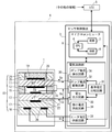
- FIG. 1 is a diagram showing a schematic configuration around an exhaust system of an internal combustion engine 100.
- FIG. 1 is a diagram showing a schematic structure of a full-range air-fuel ratio sensor 1.
- a gas concentration / humidity detection apparatus embodying the present invention
- a gas concentration / humidity detection device based on a detection signal output from a gas sensor, oxygen concentration in the detection gas and humidity when the detection gas is the atmosphere are detected.
- the sensor control device 3 that can be used will be described as an example.
- the gas sensor a full range air-fuel ratio sensor 1 in which the sensor current changes linearly according to the oxygen concentration will be described as an example.
- the internal combustion engine 100 has an engine 101 for driving an automobile.
- the engine 101 is connected to an exhaust pipe 102 for discharging exhaust gas discharged from the engine 101 to the outside of the vehicle.
- a full-range air-fuel ratio sensor 1 is disposed on the path of the exhaust pipe 102. More specifically, the full-range air-fuel ratio sensor 1 is a gas sensor that detects the gas concentration of a specific component (oxygen in the present embodiment) in the exhaust gas flowing through the exhaust passage of the exhaust pipe 102.
- the full-range air-fuel ratio sensor 1 is electrically connected to a sensor control device 3 disposed at a position away from itself through a harness (signal line) 91 and is energized and controlled by the sensor control device 3. Detect oxygen concentration.
- the sensor control device 3 is driven by the supply of electric power from the battery 80, and outputs an oxygen concentration detection signal detected using the full-range air-fuel ratio sensor 1 to the engine control device (ECU) 5.
- ECU engine control device
- air-fuel ratio feedback control of the engine 101 is performed based on the output of the full-range air-fuel ratio sensor 1.
- the exhaust gas becomes the detection target of the full-range air-fuel ratio sensor 1 as described above.
- the atmosphere flows through the exhaust pipe 102, so that the atmosphere flowing through the exhaust pipe 102 becomes the detection target of the full-range air-fuel ratio sensor 1. .
- the “detected gas” to be detected by the full-range air-fuel ratio sensor 1 includes both exhaust gas and the atmosphere.
- the full-range air-fuel ratio sensor 1 has a structure in which a sensor element 10 having an elongated and long plate shape is held in a housing (not shown).
- the full-range air-fuel ratio sensor 1 is electrically connected to a sensor control device 3 attached at a position away from the full-range air-fuel ratio sensor 1 via a harness 91 for taking out an output signal of the sensor element 10. .
- the sensor control device 3 is provided between the full-range air-fuel ratio sensor 1 and the ECU 5, and the sensor unit 4 is configured by the full-range air-fuel ratio sensor 1 and the sensor control device 3. is doing.
- the “gas concentration / humidity detection device” in the present invention corresponds to the sensor control device 3 (that is, the sensor unit 4) connected to the full-range air-fuel ratio sensor 1.
- the arrangement mode of the sensor control device 3 can be changed as appropriate.
- the sensor control device 3 may be incorporated in the ECU 5 and the entire region air-fuel ratio sensor 1 and the ECU 5 may be used as a sensor unit.
- the sensor element 10 includes solid electrolyte bodies 11 and 13 mainly composed of zirconia and insulating base bodies 12, 17, 18 and 24 mainly composed of alumina, insulating base bodies 18 and 17, solid electrolyte body 13, insulating base body 12, The solid electrolyte body 11 and the insulating base 24 are stacked in this order.
- a pair of electrodes 19 and 20 mainly composed of platinum are respectively formed on both surfaces of the solid electrolyte body 11, and similarly, a pair of electrodes 21 and 22 are also formed on both surfaces of the solid electrolyte body 13, respectively. .
- the electrode 22 is embedded between the solid electrolyte body 13 and the insulating base 24.
- Each of the solid electrolyte bodies 11 and 13 and the insulating bases 12, 17, 18, and 24 is formed in an elongated plate shape, and FIG. 2 shows a cross section orthogonal to the longitudinal direction.
- a hollow gas detection chamber 23 into which a gas to be detected can be introduced is formed on one end side in the longitudinal direction of the insulating substrate 12 while the solid electrolyte bodies 11 and 13 are used as one wall surface. At both ends of the gas detection chamber 23 in the width direction, porous diffusion rate controlling portions 15 for restricting the amount of inflow when the gas to be detected is introduced into the gas detection chamber 23 are provided.
- the electrode 20 on the solid electrolyte body 11 and the electrode 21 on the solid electrolyte body 13 are exposed in the gas detection chamber 23, respectively.
- the insulating bases 17 and 18 and the heating resistor 26 function as a heater for heating and activating the solid electrolyte bodies 11 and 13.
- the surface of the electrode 19 on the solid electrolyte body 11 is covered with a porous protective layer 25 made of ceramics (for example, alumina). That is, the electrode 19 is protected by the protective layer 25 so as not to be deteriorated by poisoning components such as silicon contained in the exhaust gas.
- the insulating base 24 laminated on the solid electrolyte body 11 has an opening so as not to cover the electrode 19, and the protective layer 25 is disposed in the opening.
- the solid electrolyte body 11 and the pair of electrodes 19 and 20 provided on both surfaces of the sensor element 10 pump oxygen into the gas detection chamber 23 from the outside or from the gas detection chamber 23 to the outside. It functions as an oxygen pump cell that pumps out oxygen (hereinafter, the solid electrolyte body 11 and the electrodes 19 and 20 are also collectively referred to as “Ip cells”).
- the solid electrolyte body 11 corresponds to the “second solid electrolyte body” of the present invention
- the pair of electrodes 19 and 20 corresponds to the “pair of second electrodes” of the present invention.
- the solid electrolyte body 13 and a pair of electrodes 21 and 22 provided on both surfaces thereof are composed of an oxygen concentration detection cell (hereinafter referred to as the solid electrolyte body 13 and the electrode 21) that generates an electromotive force according to the oxygen concentration between both electrodes. , 22 are also collectively referred to as “Vs cells”).
- the electrode 22 functions as an oxygen reference electrode that maintains an oxygen concentration that serves as a reference for detecting the oxygen concentration in the gas detection chamber 23.
- the solid electrolyte body 13 corresponds to the “first solid electrolyte body” of the present invention
- the pair of electrodes 21 and 22 corresponds to the “pair of first electrodes” of the present invention. Detailed functions of the Ip cell and the Vs cell will be described later.
- the sensor control device 3 includes a microcomputer 9 and an electric circuit unit 30 as constituent entities.
- the microcomputer 9 is a microcomputer chip on which a CPU 6, a ROM 7, a RAM 8, and the like having a known configuration are mounted.
- the ROM 7 stores a control program for causing the CPU 6 to execute each process, a humidity correction table for performing humidity correction described later, and the like.
- the electric circuit unit 30 includes a heater energization control circuit 31, a pump current drive circuit 32, a voltage output circuit 33, a minute current supply circuit 34, a reference voltage comparison circuit 35, and a pump current detection circuit 36.
- the heater energization control circuit 31 heats the heating resistor 26 by PWM energizing the voltage Vh supplied to both ends of the heating resistor 26 to heat the Ip cell and the Vs cell.
- the minute current supply circuit 34 flows a minute current Icp from the electrode 22 of the Vs cell to the electrode 21 side, and moves oxygen ions to the electrode 22 side to generate a reference oxygen concentration atmosphere.
- the electrode 22 functions as an oxygen reference electrode that serves as a reference for detecting the oxygen concentration in the gas to be detected.
- the voltage output circuit 33 detects an electromotive force Vs generated between the electrodes 21 and 22 of the Vs cell.
- the reference voltage comparison circuit 35 compares a predetermined reference voltage with the electromotive force Vs detected by the voltage output circuit 33 and feeds back the comparison result to the pump current drive circuit 32.
- the pump current drive circuit 32 controls the magnitude and direction of the pump current Ip that flows between the electrodes 19 and 20 of the Ip cell based on the comparison result obtained from the reference voltage comparison circuit 35. As a result, oxygen is pumped into the gas detection chamber 23 and oxygen is pumped out of the gas detection chamber 23 by the Ip cell.
- the pump current detection circuit 36 converts the pump current Ip flowing between the electrodes 19 and 20 of the Ip cell into a voltage and outputs it to the microcomputer 9 as a detection signal.
- first reference voltage and second reference voltage there are two reference voltages (first reference voltage and second reference voltage) as reference voltages to be compared with the electromotive force Vs by the reference voltage comparison circuit 35.
- the first reference voltage is introduced into the gas detection chamber 23 when the comparison result of the voltage output circuit 33 is fed back to the pump current drive circuit 32 and the oxygen concentration in the atmosphere in the gas detection chamber 23 is controlled.
- the voltage value (for example, 450 mV) is set such that moisture (H 2 O) in the detection gas does not substantially dissociate.
- the second reference voltage is introduced into the gas detection chamber 23 when the comparison result of the voltage output circuit 33 is fed back to the pump current drive circuit 32 and the oxygen concentration in the atmosphere in the gas detection chamber 23 is controlled.
- the voltage value (for example, 1000 mV) is set such that moisture (H 2 O) in the detected gas is dissociated.
- the first reference voltage is always used as the reference voltage to be compared with the electromotive force Vs, and the oxygen concentration in the detected gas is calculated based on the pump current Ip.
- the second reference voltage is used when correcting the humidity of the air-fuel ratio sensor 1, and details will be described later.
- the pump current drive circuit 32, the voltage output circuit 33, and the reference voltage comparison circuit 35 correspond to the “current control means” of the present invention.
- the reference voltage compared with the electromotive force Vs corresponds to the “control target voltage” of the present invention, and the first reference voltage and the second reference voltage are “first voltage” and “second voltage” of the present invention, respectively. Is equivalent to.
- the ECU 5 is a device for electronically controlling driving of the automobile engine 101 and the like.
- the ECU 5 uses a microcomputer chip having a known configuration of CPU, ROM, RAM, etc., and controls the fuel injection timing and ignition timing according to the execution of the control program.
- an output (detection signal) corresponding to the oxygen concentration in the gas to be detected is input from the sensor control device 3.
- signals from other sensors for example, information such as a crank angle at which the piston position and the rotation speed of the engine 101 can be detected, coolant temperature, combustion pressure, etc. are also input.
- a first reference voltage (for example, 450 mV) is set as a reference voltage to be compared by the reference voltage comparison circuit 35.
- a minute current Icp is first caused to flow from the electrode 22 to the electrode 21 of the Vs cell by the minute current supply circuit 34.
- oxygen in the gas to be detected is pumped from the electrode 21 side to the electrode 22 side through the solid electrolyte body 13, and the electrode 22 functions as an oxygen reference electrode.
- the voltage output circuit 33 detects an electromotive force Vs generated between the electrodes 21 and 22, and the reference voltage comparison circuit 35 compares the electromotive force Vs with a reference voltage.
- the pump current drive circuit 32 controls the magnitude and direction of the pump current Ip that flows between the electrodes 19 and 20 of the Ip cell so that the electromotive force Vs becomes the reference voltage based on the comparison result by the reference voltage comparison circuit 35.
- the air-fuel ratio of the exhaust gas flowing into the gas detection chamber 23 is richer than the stoichiometric air-fuel ratio, the oxygen concentration in the exhaust gas is thin, so that oxygen is introduced into the gas detection chamber 23 from the outside in the Ip cell.
- the pump current Ip flowing between the electrodes 19 and 20 is controlled so as to pump in.
- the air-fuel ratio of the exhaust gas flowing into the gas detection chamber 23 is leaner than the stoichiometric air-fuel ratio, a large amount of oxygen is present in the exhaust gas, so that in the Ip cell from the gas detection chamber 23 to the outside.
- the pump current Ip flowing between the electrodes 19 and 20 is controlled so as to pump out oxygen.
- the pump current Ip at this time is converted into a voltage by the pump current detection circuit 36 and output to the ECU 5 as an output (detection signal) of the full-range air-fuel ratio sensor 1.
- the ECU 5 can specify the oxygen concentration contained in the detected gas, and hence the air-fuel ratio of the exhaust gas, based on the magnitude and direction of the pump current Ip output from the full-range air-fuel ratio sensor 1.
- the sensor unit 4 (full-range air-fuel ratio sensor 1 and sensor control device 3) has the same configuration as the conventional sensor unit, and the oxygen concentration of the detection gas (the air-fuel ratio of the exhaust gas) ) Detection operation is the same as that of the prior art.
- the sensor control device 3 can detect not only the oxygen concentration of the gas to be detected (the air-fuel ratio of the exhaust gas) but also the humidity when the gas to be detected is the atmosphere using the full-range air-fuel ratio sensor 1. it can.
- the sensor output from the full-range air-fuel ratio sensor 1 can be corrected according to the humidity in the air atmosphere, which will be described in detail below.
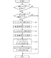
- a program for executing each process shown in FIG. 3 is also stored in the ROM 7 (see FIG. 2), and is executed by the CPU 6 (see FIG. 2). This main process is periodically executed at predetermined timings while the internal combustion engine 100 is being driven.
- the drive control of the heater energization control circuit 31, the pump current drive circuit 32, the voltage output circuit 33, the minute current supply circuit 34, the reference voltage comparison circuit 35, and the pump current detection circuit 36 included in the electric circuit unit 30 is shown in FIG.
- the main process shown in FIG. Note that, after the internal combustion engine is started and before the main process shown in FIG. 3 is first executed, the reference voltage of the reference voltage comparison circuit 35 is set to the first reference voltage (for example, 450 mV) in the sensor control device 3.
- the pump current drive circuit 32 controls the energization of the Ip current to the Ip cell.
- the microcomputer 9 receives a signal indicating whether or not fuel is being supplied in the internal combustion engine 100 from the ECU 5 every predetermined time, and stores the received signal in the RAM 8 as needed by a separately executed program. .
- S1 it is determined whether or not the fuel cut signal is received based on whether or not the fuel cut signal is stored in the RAM 8 as the latest signal received from the ECU 5.
- the exhaust passage of the exhaust pipe 102 is filled with the atmosphere. That is, since the sensor element 10 is exposed to the atmosphere, it is determined that the gas to be detected is the atmosphere (S1: YES).
- a timer (not shown) is updated every predetermined period and stored in the RAM 8 by a timer update program separately executed during a period in which the fuel cut signal is continuously received. Therefore, the timer (not shown) indicates the length of the period during which the fuel cut signal is continuously received, that is, the elapsed time from the point in time when the fuel supply is stopped (that is, when the fuel cut is started).
- S3 it is determined whether or not a predetermined time has elapsed since the fuel supply was stopped in the internal combustion engine 100 (S3). In the process of S3, it is determined whether or not the timer stored in the RAM 8 has passed a predetermined time stored in the ROM 7 in advance. If it is determined that a predetermined time has elapsed since the stop of fuel supply (S3: YES), the exhaust passage of the exhaust pipe 102 is sufficiently filled with the atmosphere, and the atmosphere around the sensor element 10 is an atmosphere with a known oxygen concentration. It has become.
- the process proceeds to S5, and the pump current Ip flowing between the electrodes 19 and 20 of the Ip cell when the reference voltage set by the reference voltage comparison circuit 35 is the first reference voltage (for example, 450 mV) is It reads as “Ip_primary” through the pump current detection circuit 36 (S5). This read “IP_primary” is stored in the RAM 8.
- S7 a process of changing the reference voltage set in the reference voltage comparison circuit 35 from the first reference voltage to the second reference voltage (for example, 1000 mV) is executed (S7).
- the process proceeds to S9, and the pump current Ip that the reference voltage set by the reference voltage comparison circuit 35 flows between the electrodes 19 and 20 of the Ip cell under the second reference voltage is converted into a pump current detection circuit. It is read as “Ip_secondary” via S36 (S9). The read “Ip_secondary” is stored in the RAM 8.
- a process of changing the reference voltage set in the reference voltage comparison circuit 35 from the second reference voltage to the first reference voltage is executed (S11).
- the moisture content of the detected gas is calculated from “Ip_primary” and “Ip_secondary” read into the RAM 8 (S13).
- the difference Ip current indicates the oxygen concentration derived from humidity in the detected gas (that is, the amount of water in the detected gas), and consequently the detected gas. Indicates atmospheric humidity.
- a correction value indicating the error ⁇ Ip of the Ip current caused by the atmospheric humidity is determined based on the above “Ip_primary” and the water amount calculated in S13 (S15).
- Ip current errors ⁇ Ip corresponding to combinations of the Ip current indicated by “Ip_primary” and the moisture content of the gas to be detected are set.
- an IP current error ⁇ IP corresponding to the combination of “Ip_primary” and the amount of moisture is determined as a correction value.
- the correction value determined in S15 is set in a predetermined storage area of the RAM 8.
- Ip_primary used for calculating the water content in S13 is the process of S5 immediately before S7, which is a process of changing the reference voltage set in the reference voltage comparison circuit 35 from the first reference voltage to the second reference voltage. It is preferable to read in. As a result, the time difference between the detection timing of “Ip_primary” and the detection timing of “Ip_secondary” is reduced, and the humidity changes after “Ip_primary” is detected until “Ip_secondary” is detected. Is suppressed.
- the humidity correction table in the ROM 7 is set by performing sampling of the entire region air-fuel ratio sensor 1 as follows. That is, the pump current Ip output according to the reference voltage is detected by changing only the humidity condition in a state where the entire range air-fuel ratio sensor 1 is exposed to the air atmosphere of the same temperature condition. Note that the magnitude of the pump current Ip output when controlled to the same reference voltage may differ depending on the individual difference or performance of the full-range air-fuel ratio sensor 1. Therefore, it is preferable that the sampling of the full-range air-fuel ratio sensor 1 is performed for a plurality of full-range air-fuel ratio sensors 1 having different output characteristics of the pump current Ip.
- the sampling result of the entire region air-fuel ratio sensor 1 as described above will be exemplified.
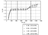
- 4 to 7 show that the entire range air-fuel ratio sensor 1 is exposed to the air atmosphere of the same temperature condition “25 ° C.”, and the humidity condition is “20%”, “50%”, “80%” as relative humidity.
- the sampling results of detecting the pump current Ip output from the full-range air-fuel ratio sensor 1 in accordance with a reference voltage that is variable within a predetermined width in the case where “100%” and “100%” are made different are illustrated.
- the relative humidity is “20%”, “50%”, “80%”, and “100%”
- the water content in the gas composition (volume ratio) in the atmosphere is “0.38%”, “0.95%”, “1.52%”, and “1.89%”.
- FIGS. 4 and 5 illustrate the sampling results of the full-range air-fuel ratio sensor 1 in which the output tendency of the Ip current is relatively large.
- the pump current Ip increases as the reference voltage increases.
- the reference voltage is higher than “200 mV”
- oxygen contained in the gas to be detected can be sufficiently moved by the solid electrolyte body 13, and the pump current Ip is almost stabilized.
- the reference voltage is higher than “900 mV”
- oxygen can be dissociated from the moisture contained in the gas to be detected in the solid electrolyte body 13, and the pump current Ip increases.
- the increase range of the pump current Ip is larger as the entire range air-fuel ratio sensor 1 is in a higher humidity condition, while the increase in the pump current Ip is higher as the entire range air-fuel ratio sensor 1 is in a lower humidity condition.
- the width is small.
- each humidity condition “20%” water content 0.38%
- “50%” water content 0.95%
- “80%” The pump current Ip of the first reference voltage (here 450 mV) and the pump current of the second reference voltage (here 1000 mV) at a moisture content of 1.52%) and “100%” (moisture content of 1.89%)
- the errors ⁇ Ip compared with Ip are “0.0304 mA”, “0.0779 mA”, “0.1242 mA”, and “0.1504 mA”, respectively.
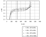
- FIGS. 6 and 7 illustrate the sampling results of the full-range air-fuel ratio sensor 1 in which the output tendency of the pump current Ip is relatively small. As shown in FIG. 6, even when the output tendency of the pump current Ip is relatively small, the behavior of the pump current Ip according to the magnitude of the reference voltage is a case where the output tendency is relatively large (FIG. 4). It is the same.
- each humidity condition “20%” water content 0.38%
- “50%” water content 0.95%
- “80%” The pump current Ip of the first reference voltage (here 450 mV) and the pump current of the second reference voltage (here 1000 mV) at a moisture content of 1.52%) and “100%” (moisture content of 1.89%)
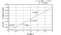
- the errors ⁇ Ip compared to Ip are “0.0575 mA”, “0.1044 mA”, “0.1616 mA”, and “0.2784 mA”, respectively.
- the pump current error ⁇ Ip (that is, the correction value) corresponding to the combination of the pump current Ip and the moisture content of the gas to be detected is the humidity of the ROM 7. It is preset in the correction table.
- correlation functions corresponding to the pump currents Ip may be set instead of the above correction values. In this case, in S15 described above, based on the correlation function corresponding to “Ip_primary”, the pump current error ⁇ Ip corresponding to the moisture amount calculated in S13 is calculated as a correction value.
- the main process (FIG. 3) is terminated.
- the correction value set in the RAM 8 is applied to the pump current detection circuit 36 when the reference voltage of the reference voltage comparison circuit 35 is set to the first reference voltage in a separate process in the microcomputer 9 (CPU 6). This is used as a correction value (Ip current error ⁇ Ip) of the pump current Ip detected via
- the pump current Ip separately detected thereafter by the microcomputer 9 (CPU 6) is corrected by the correction value.
- the microcomputer 9 outputs the pump current Ip corrected using the correction value to the ECU 5 as an oxygen concentration detection signal, so that the ECU 5 can calculate the oxygen concentration and the air-fuel ratio with high accuracy, and hence the precision. Air-fuel ratio feedback control can be realized.
- the CPU 6 that executes S1 corresponds to the “atmosphere discrimination means” of the present invention
- the CPU 6 that executes the pump current detection circuit 36 and S5 is the “first” of the present invention.
- the CPU 6 that executes S7 and S11 corresponds to the “voltage detection means” of the present invention
- the CPU 6 that executes the pump current detection circuit 36 and S9 corresponds to the “second current detection means” of the present invention.
- the CPU 6 that executes S13 corresponds to “humidity detecting means” of the present invention
- the CPU 6 that executes S15 corresponds to “correction value determining means” of the present invention.
- microcomputer 9 that outputs the pump current Ip corrected by using the correction value of the above-described embodiment to the ECU 5 as an oxygen concentration detection signal and the ECU 5 that calculates the oxygen concentration and the air-fuel ratio based on the detection signal are included in the present invention. It corresponds to “gas concentration detection means”.
- the present invention is not limited to the embodiment described in detail above, and various modifications may be made without departing from the gist of the present invention.
- the full-range air-fuel ratio sensor 1 that detects the oxygen concentration in the detection gas is used as the gas sensor that detects the gas concentration of the specific component in the detection gas
- the present invention is not limited to this.
- humidity correction can be performed in the same manner as described above.
- the detected gas is the atmosphere based on the fuel cut signal output when the fuel supply to the internal combustion engine is stopped.
- the present invention is not limited to this.
- the full-range air-fuel ratio sensor 1 includes a device that fills the atmosphere around the sensor element 10 with a correction gas having a known oxygen concentration, based on a signal output when the correction gas is filled. It may be determined that the gas to be detected is air.
- the pump current Ip is output from the sensor control device 3 to the ECU 5, and the ECU 5 specifies the oxygen concentration in the detected gas, and thus the air-fuel ratio of the exhaust gas, based on the pump current Ip. It is not limited to this.
- the microcomputer 9 (CPU 6) specifies the oxygen concentration in the detected gas and the air-fuel ratio of the exhaust gas based on the pump current Ip and the correction value determined in S15 shown in FIG.
- the oxygen concentration and the air / fuel ratio may be output to the ECU 5.
- the microcomputer 9 for identifying the oxygen concentration in the detected gas and the air-fuel ratio of the exhaust gas based on the pump current Ip and the correction value determined in S15 shown in FIG. corresponds to “means”.
Landscapes
- Chemical & Material Sciences (AREA)
- Life Sciences & Earth Sciences (AREA)
- Health & Medical Sciences (AREA)
- Physics & Mathematics (AREA)
- Chemical Kinetics & Catalysis (AREA)
- Electrochemistry (AREA)
- Molecular Biology (AREA)
- Analytical Chemistry (AREA)
- Biochemistry (AREA)
- General Health & Medical Sciences (AREA)
- General Physics & Mathematics (AREA)
- Immunology (AREA)
- Pathology (AREA)
- Combined Controls Of Internal Combustion Engines (AREA)
Abstract
Description
。
y=0.0799x+0.0011
このとき、相関係数Rの2乗値(R-2乗値)は、以下となる。
R2=0.9991
y=0.1368x+0.0117
このとき、相関係数Rの2乗値(R-2乗値)は、以下となる。
R2=0.9015
3 センサ制御装置
4 センサユニット
9 マイクロコンピュータ
10 センサ素子
11 固体電解質体
13 固体電解質体
23 ガス検出室
32 ポンプ電流駆動回路
33 電圧出力回路
34 微小電流供給回路
35 基準電圧比較回路
36 ポンプ電流検出回路
100 内燃機関
Claims (4)
- 第1固体電解質体及び当該第1固体電解質体上に形成された一対の第1電極を有し、当該一対の第1電極のうちの一方の電極が、被検出ガスが導入される検出室内に配置され、他方の電極が基準となる酸素濃度雰囲気に晒される酸素濃度検出セルと、
第2固体電解質体及び当該第2固体電解質体上に形成された一対の第2電極を有し、前記一対の第2電極のうちの一方の電極が前記検出室内に配置され、当該一対の第2電極間に流れる電流に応じて、前記検出室に導入された前記被検出ガスに含まれる酸素の汲み出し又は汲み入れを行う酸素ポンプセルと
を備えるガスセンサを有し、前記ガスセンサに接続されて前記被検出ガス中の特定成分のガス濃度及び前記被検出ガスが大気であるときの湿度を検出するガス濃度湿度検出装置であって、
前記検出室内の酸素濃度と前記酸素基準室内の酸素濃度との差異に起因して前記一対の第1電極間に生じる電圧を検出し、当該一対の第1電極間に生じる電圧が制御目標電圧となるように前記一対の第2電極間に流れる電流を制御する電流制御手段と、
前記被検出ガスが大気であるか否かを判別する雰囲気判別手段と、
前記制御目標電圧を前記第1の電圧に設定する一方、前記雰囲気判別手段によって前記被検出ガスが大気であると判別された場合に、前記制御目標電圧を前記第1の電圧よりも大きい第2の電圧に設定する電圧設定手段と、
前記一対の第1電極間に第1の電圧が生じた状態において、前記一対の第2電極間に流れる第1電流を検出する第1電流検出手段と、
前記一対の第1電極間に前記第2の電圧が生じた状態において、前記一対の第2電極間に流れる第2電流を検出する第2電流検出手段と、
前記雰囲気判別手段によって前記被検出ガスが大気であると判別されているときに前記第1電流検出手段によって検出された前記第1電流と、前記電圧設定手段によって前記第1の電圧を前記第2の電圧に変更した後に前記第2電流検出手段によって検出された前記第2電流とに基づいて、前記被検出ガスの湿度を検出する湿度検出手段とを備えたことを特徴とするガス濃度湿度検出装置。 - 前記第1電流検出手段によって検出された前記第1電流に基づいて、前記特定成分のガス濃度を検出するガス濃度検出手段と、
前記雰囲気判別手段によって前記被検出ガスが大気であると判別されたときに前記第1電流検出手段によって検出された前記第1電流と、前記湿度検出手段によって検出された前記湿度とに基づいて、前記ガス濃度検出手段によって検出されるガス濃度を補正する補正値を決定する補正値決定手段とを備えたことを特徴とする請求項1に記載のガス濃度湿度検出装置。 - 前記湿度検出手段は、前記第2電流から前記第1電流を減じた差分値に基づいて前記湿度を求めることを特徴とする請求項1又は2に記載のガス濃度湿度検出装置。
- 前記湿度検出手段は、前記第1電流検出手段によって検出される前記第1電流のうちで、前記制御目標電圧が前記第2の電圧に設定される直前に検出された前記第1電流に基づいて、前記湿度を検出することを請求項1~3のいずれかに記載のガス濃度湿度検出装置。
Priority Applications (2)
| Application Number | Priority Date | Filing Date | Title |
|---|---|---|---|
| US13/147,988 US8603310B2 (en) | 2009-06-05 | 2010-04-19 | Gas-concentration/humidity detection apparatus |
| DE112010002225T DE112010002225T5 (de) | 2009-06-05 | 2010-04-19 | Vorrichtung zum Erfassen der Gaskonzentration/der Feuchtigkeit |
Applications Claiming Priority (2)
| Application Number | Priority Date | Filing Date | Title |
|---|---|---|---|
| JP2009136184A JP5021697B2 (ja) | 2009-06-05 | 2009-06-05 | ガス濃度湿度検出装置 |
| JP2009-136184 | 2009-06-05 |
Publications (1)
| Publication Number | Publication Date |
|---|---|
| WO2010140293A1 true WO2010140293A1 (ja) | 2010-12-09 |
Family
ID=43297436
Family Applications (1)
| Application Number | Title | Priority Date | Filing Date |
|---|---|---|---|
| PCT/JP2010/002808 Ceased WO2010140293A1 (ja) | 2009-06-05 | 2010-04-19 | ガス濃度湿度検出装置 |
Country Status (4)
| Country | Link |
|---|---|
| US (1) | US8603310B2 (ja) |
| JP (1) | JP5021697B2 (ja) |
| DE (1) | DE112010002225T5 (ja) |
| WO (1) | WO2010140293A1 (ja) |
Cited By (1)
| Publication number | Priority date | Publication date | Assignee | Title |
|---|---|---|---|---|
| DE102013200647B4 (de) | 2012-01-17 | 2023-06-07 | Ngk Spark Plug Co., Ltd. | Korrekturkoeffizienten-Setzverfahren für eine Gaskonzentrations-Erfassungsvorrichtung |
Families Citing this family (26)
| Publication number | Priority date | Publication date | Assignee | Title |
|---|---|---|---|---|
| JP5739839B2 (ja) * | 2012-05-31 | 2015-06-24 | 日本特殊陶業株式会社 | ガスセンサ制御装置 |
| JP2013250164A (ja) * | 2012-05-31 | 2013-12-12 | Ngk Spark Plug Co Ltd | ガスセンサ制御装置 |
| JP5788834B2 (ja) * | 2012-05-31 | 2015-10-07 | 日本特殊陶業株式会社 | ガスセンサ制御装置 |
| JP5767607B2 (ja) * | 2012-05-31 | 2015-08-19 | 日本特殊陶業株式会社 | ガスセンサ制御装置 |
| DE102013212217A1 (de) * | 2012-07-12 | 2014-05-15 | Ford Global Technologies, Llc | Indirekte Messung der relativen Luftfeuchtigkeit |
| JP6116320B2 (ja) * | 2013-03-29 | 2017-04-19 | 株式会社堀場製作所 | 排ガスサンプリング装置及び排ガスサンプリング方法 |
| RU2540450C1 (ru) * | 2013-09-13 | 2015-02-10 | Федеральное государственное бюджетное учреждение науки Институт высокотемпературной электрохимии Уральского отделения Российской Академии наук | Способ измерения кислородосодержания и влажности газа |
| JP6252940B2 (ja) * | 2013-12-26 | 2017-12-27 | ボルボトラックコーポレーション | NOx計測装置及びNOx計測方法 |
| US9404432B2 (en) * | 2014-01-09 | 2016-08-02 | Ford Global Technologies, Llc | Methods and systems for fuel ethanol content determination via an oxygen sensor |
| US9376968B2 (en) * | 2014-01-09 | 2016-06-28 | Ford Global Technologies, Llc | Methods and systems for fuel ethanol content determination via an oxygen sensor |
| RU2691275C2 (ru) * | 2014-06-05 | 2019-06-11 | Форд Глобал Текнолоджиз, Ллк | Способ определения содержания этанола в топливе при помощи датчика кислорода (варианты) |
| US9885685B2 (en) * | 2014-10-10 | 2018-02-06 | Ford Global Technologies, Llc | Compensating oxygen sensor aging |
| JP6323357B2 (ja) | 2015-02-09 | 2018-05-16 | 株式会社デンソー | 内燃機関制御装置 |
| US9709482B2 (en) | 2015-02-19 | 2017-07-18 | Ford Global Technologies, Llc | Methods and systems for humidity determination via an oxygen sensor |
| US9528448B2 (en) | 2015-02-19 | 2016-12-27 | Ford Global Technologies, Llc | Methods and system for fuel ethanol content estimation and engine control |
| US9611799B2 (en) | 2015-02-19 | 2017-04-04 | Ford Global Technologies, Llc | Methods and systems for estimating an air-fuel ratio with a variable voltage oxygen sensor |
| US9664594B2 (en) | 2015-02-19 | 2017-05-30 | Ford Global Technologies, Llc | Ambient humidity detection transmission shifts |
| JP6587815B2 (ja) | 2015-03-09 | 2019-10-09 | 日本特殊陶業株式会社 | センサ制御装置およびセンサ制御システム |
| JP6233343B2 (ja) * | 2015-04-02 | 2017-11-22 | トヨタ自動車株式会社 | ガスセンサの異常診断システム |
| DE102016207516B4 (de) * | 2016-05-02 | 2021-10-28 | Vitesco Technologies GmbH | Verfahren zur Alterungsbestimmung einer zur Ermittlung einer Gaskonzentration eines Gasgemischs ausgebildeten Sonde einer Brennkraftmaschine |
| US9920699B1 (en) * | 2016-10-19 | 2018-03-20 | Ford Global Technologies, Llc | Methods and system for exhaust gas recirculation estimation via an exhaust oxygen sensor |
| KR101850903B1 (ko) * | 2016-10-28 | 2018-05-30 | 울산과학기술원 | 습도 센서 및 이를 포함하는 습도 보정 가스 센서 |
| GB201903473D0 (en) * | 2019-03-14 | 2019-05-01 | Sumitomo Chemical Co | Interferent and baseline drift correcting gas sensor system |
| US10746118B1 (en) * | 2019-07-02 | 2020-08-18 | Delphi Technologies Ip Limited | Compensator circuitry and method for an oxygen sensor |
| DE102022132507A1 (de) * | 2021-12-16 | 2023-06-22 | Ngk Insulators, Ltd. | Gassensor und Verfahren zur Diagnose eines Feuchtigkeitsabsorptionszustands eines Gassensors |
| JP7877165B2 (ja) | 2022-10-21 | 2026-06-22 | Ngk株式会社 | ガスセンサ |
Citations (4)
| Publication number | Priority date | Publication date | Assignee | Title |
|---|---|---|---|---|
| JPS62150151A (ja) * | 1985-12-24 | 1987-07-04 | Fujikura Ltd | 気体濃度測定方法 |
| JPS6385351A (ja) * | 1986-09-30 | 1988-04-15 | Ngk Insulators Ltd | 高温ガス中の二酸化炭素および水分測定装置 |
| JPH06265516A (ja) * | 1993-03-16 | 1994-09-22 | Matsushita Electric Ind Co Ltd | 酸素湿度センサ |
| JPH10267885A (ja) * | 1997-03-21 | 1998-10-09 | Ngk Spark Plug Co Ltd | ガスセンサの補正方法 |
Family Cites Families (8)
| Publication number | Priority date | Publication date | Assignee | Title |
|---|---|---|---|---|
| JPH0660884B2 (ja) * | 1983-09-19 | 1994-08-10 | トヨタ自動車株式会社 | 湿度測定装置 |
| JPS622149A (ja) | 1985-06-27 | 1987-01-08 | Nissan Motor Co Ltd | 空燃比検出装置 |
| JP3529567B2 (ja) * | 1996-03-21 | 2004-05-24 | 日本特殊陶業株式会社 | ガスセンサ |
| EP0878709B1 (en) | 1997-03-21 | 2004-08-25 | NGK Spark Plug Co. Ltd. | Method and apparatus for measuring NOx gas concentration |
| JP3589872B2 (ja) | 1997-09-11 | 2004-11-17 | 日本特殊陶業株式会社 | 排出ガス濃度検出方法及びその装置 |
| JPH11160272A (ja) * | 1997-11-25 | 1999-06-18 | Nippon Soken Inc | ガス濃度検出装置 |
| JP4466709B2 (ja) * | 2007-09-27 | 2010-05-26 | 株式会社デンソー | ガスセンサ制御装置 |
| US8522760B2 (en) * | 2009-12-04 | 2013-09-03 | Ford Global Technologies, Llc | Fuel alcohol content detection via an exhaust gas sensor |
-
2009
- 2009-06-05 JP JP2009136184A patent/JP5021697B2/ja active Active
-
2010
- 2010-04-19 DE DE112010002225T patent/DE112010002225T5/de active Pending
- 2010-04-19 WO PCT/JP2010/002808 patent/WO2010140293A1/ja not_active Ceased
- 2010-04-19 US US13/147,988 patent/US8603310B2/en not_active Expired - Fee Related
Patent Citations (4)
| Publication number | Priority date | Publication date | Assignee | Title |
|---|---|---|---|---|
| JPS62150151A (ja) * | 1985-12-24 | 1987-07-04 | Fujikura Ltd | 気体濃度測定方法 |
| JPS6385351A (ja) * | 1986-09-30 | 1988-04-15 | Ngk Insulators Ltd | 高温ガス中の二酸化炭素および水分測定装置 |
| JPH06265516A (ja) * | 1993-03-16 | 1994-09-22 | Matsushita Electric Ind Co Ltd | 酸素湿度センサ |
| JPH10267885A (ja) * | 1997-03-21 | 1998-10-09 | Ngk Spark Plug Co Ltd | ガスセンサの補正方法 |
Cited By (1)
| Publication number | Priority date | Publication date | Assignee | Title |
|---|---|---|---|---|
| DE102013200647B4 (de) | 2012-01-17 | 2023-06-07 | Ngk Spark Plug Co., Ltd. | Korrekturkoeffizienten-Setzverfahren für eine Gaskonzentrations-Erfassungsvorrichtung |
Also Published As
| Publication number | Publication date |
|---|---|
| US8603310B2 (en) | 2013-12-10 |
| DE112010002225T5 (de) | 2012-06-28 |
| US20110290015A1 (en) | 2011-12-01 |
| JP2010281732A (ja) | 2010-12-16 |
| JP5021697B2 (ja) | 2012-09-12 |
Similar Documents
| Publication | Publication Date | Title |
|---|---|---|
| JP5021697B2 (ja) | ガス濃度湿度検出装置 | |
| US6214207B1 (en) | Method and apparatus for measuring oxygen concentration and nitrogen oxide concentration | |
| JP4814996B2 (ja) | 測定センサの温度の決定方法 | |
| JP5074358B2 (ja) | ガスセンサ制御装置、及び窒素酸化物濃度検出方法 | |
| US9052279B2 (en) | Gas sensor apparatus and method for controlling the same | |
| JP7303129B2 (ja) | ガスセンサ | |
| JP4415771B2 (ja) | ガス濃度検出装置 | |
| US10627365B2 (en) | Sensor control apparatus and sensor control system | |
| JP5817581B2 (ja) | 内燃機関の排出ガス浄化装置 | |
| JP2016090264A (ja) | ガスセンサ装置 | |
| JP5767607B2 (ja) | ガスセンサ制御装置 | |
| JP6551314B2 (ja) | ガスセンサ制御装置 | |
| JP4905726B2 (ja) | 空燃比検出装置 | |
| WO2017068919A1 (ja) | 排出ガスセンサの制御装置及び排出ガスセンサシステム | |
| JP2017053802A (ja) | ガス濃度湿度検出装置及びガス濃度湿度検出方法 | |
| JP4696760B2 (ja) | センサ特性較正装置 | |
| US9671311B2 (en) | Method and device for determining a lambda air ratio using a gas sensor | |
| JP2024132120A (ja) | 濃度情報取得装置、及び濃度情報取得方法 | |
| JP3734685B2 (ja) | 空燃比センサのセンサ素子温度検出装置 | |
| JP2023145123A (ja) | NOxセンサ | |
| JPH11183432A (ja) | ガス成分濃度測定装置 | |
| JP2004156916A (ja) | 酸素センサ | |
| JP2017026413A (ja) | ガス濃度湿度検出装置 |
Legal Events
| Date | Code | Title | Description |
|---|---|---|---|
| 121 | Ep: the epo has been informed by wipo that ep was designated in this application |
Ref document number: 10783081 Country of ref document: EP Kind code of ref document: A1 |
|
| WWE | Wipo information: entry into national phase |
Ref document number: 13147988 Country of ref document: US |
|
| WWE | Wipo information: entry into national phase |
Ref document number: 1120100022259 Country of ref document: DE Ref document number: 112010002225 Country of ref document: DE |
|
| 122 | Ep: pct application non-entry in european phase |
Ref document number: 10783081 Country of ref document: EP Kind code of ref document: A1 |