WO2010140231A1 - ファスナーストリンガー - Google Patents
ファスナーストリンガー Download PDFInfo
- Publication number
- WO2010140231A1 WO2010140231A1 PCT/JP2009/060135 JP2009060135W WO2010140231A1 WO 2010140231 A1 WO2010140231 A1 WO 2010140231A1 JP 2009060135 W JP2009060135 W JP 2009060135W WO 2010140231 A1 WO2010140231 A1 WO 2010140231A1
- Authority
- WO
- WIPO (PCT)
- Prior art keywords
- fastener
- cross
- sectional area
- meshing
- tooth
- Prior art date
- Legal status (The legal status is an assumption and is not a legal conclusion. Google has not performed a legal analysis and makes no representation as to the accuracy of the status listed.)
- Ceased
Links
Images






Classifications
-
- A—HUMAN NECESSITIES
- A44—HABERDASHERY; JEWELLERY
- A44B—BUTTONS, PINS, BUCKLES, SLIDE FASTENERS, OR THE LIKE
- A44B19/00—Slide fasteners
- A44B19/02—Slide fasteners with a series of separate interlocking members secured to each stringer tape
- A44B19/04—Stringers arranged edge-to-edge when fastened, e.g. abutting stringers
- A44B19/06—Stringers arranged edge-to-edge when fastened, e.g. abutting stringers with substantially rectangular members having interlocking projections and pieces
-
- A—HUMAN NECESSITIES
- A44—HABERDASHERY; JEWELLERY
- A44B—BUTTONS, PINS, BUCKLES, SLIDE FASTENERS, OR THE LIKE
- A44B19/00—Slide fasteners
- A44B19/24—Details
- A44B19/40—Connection of separate, or one-piece, interlocking members to stringer tapes; Reinforcing such connections, e.g. by stitching
- A44B19/403—Connection of separate interlocking members
Definitions
- the present invention relates to a fastener stringer for a slide fastener in which the engagement tooth is broken when an excessive lateral pulling force is applied.
- Japanese Utility Model Publication No. 53-71661 is a manual injection molding machine that is used to attach a new service tooth by injection molding to a fastener stringer that has previously lost some of the service teeth in the service tooth row. It is shown in the gazette (patent document 1).
- the fastener tape is formed by promoting the cooling after injection molding by forming a recess in the leg portion, etc., and reducing the cavity generated inside the engagement gear during cooling. It is said that the attachment strength between the tooth and the tooth can be greatly increased.
- the use of stationary nets has continued for 2 years and 3 years. Not only will the net itself be damaged, but the slide fasteners used for joining will also be damaged. There is a case.
- the slide fastener used for joining such a stationary net is one that can withstand a strong lateral pulling force (for example, 250 kg / 25 mm).
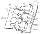
- FIG. 14 is a diagram for explaining a state of damage that occurs in the engagement teeth 914 of the slide fastener 910 and the fastener tape when a strong lateral pulling force is applied to the conventional slide fastener 910 in the meshed state.
- the damage state which may occur in the conventional slide fastener 910 will be described.
- the slide fastener 910 has a pair of left and right fastener stringers 916 and 917.
- the fastener stringers 916 and 917 are formed by attaching a plurality of engagement teeth 912, 913, and 914 to opposing side edges of the respective fastener tapes.
- separating a pair of right and left fastener stringers 916 and 917 is abbreviate
- breakage that occurs in the engagement teeth 912, 913, and 914 that are in an engaged state can be mentioned.
- the breakage 921 is generally generated in the constricted neck portion 78 having the smallest cross-sectional area.
- FIG. 14 a state in which a fracture 921 occurs in the meshing neck 78 having a smaller cross-sectional area than the meshing head 70 of the service tooth 914 is shown.
- the operation of removing the tooth from the fastener tape is generally not easy.
- the work of removing a large tooth having a mounting pitch of about 15 mm to 30 mm, such as a tooth of a slide fastener used for joining a stationary net. Will be difficult.
- slide fasteners used for applications that require restoration not only have a strong lateral pulling force that can be tolerated, but also do not break in the fastener tape, and have a structure that breaks or deforms in parts other than the meshing neck portion of the engagement tooth
- the recessed part is formed in the leg part of the slide fastener described in patent document 2
- the purpose of forming this recessed part is to promote the cooling after the injection molding, so that the fastener tape and the engagement tooth The purpose is to increase the mounting strength. Therefore, when a lateral pulling force is applied to the slide fastener described in Patent Document 2 and the lateral pulling force is increased, the slide fastener is separated due to breakage at the meshing neck portion having a small cross-sectional area. It becomes a state.
- the present invention has been made in view of the above-described conventional problems, and even when a lateral pulling force exceeding the breaking strength is applied and a part of the engagement tooth is broken, the meshing head and engagement of the broken engagement tooth
- An object of the present invention is to provide a fastener stringer provided with a tooth that does not leave a broken piece of the broken tooth on the fastener tape while maintaining a meshed state with the other side of the tooth.
- the present invention provides a fastener stringer in which a plurality of engagement teeth are respectively attached to opposite side edges of a pair of left and right fastener tapes, and the engagement teeth are arranged on one surface in a direction perpendicular to the fastener tape surface.
- the first surface is the second surface and the other surface is the second surface
- the first leg is attached to the first surface across the edge of the fastener tape
- the second leg is attached to the second surface.
- a meshing neck that extends from the first and second legs toward the mating tooth, and a meshing head that further extends in the same direction from the meshing neck and bulges in the length direction of the fastener tape
- a minimum cross-sectional area of the meshing neck portion is Sn, and at least a cross-section of at least one of the first and second leg portions in the width direction of the fastener tape, the length of the fastener tape being Cross section parallel to the vertical direction
- the cross-sectional area in the case of the Sf characterized by satisfying the relation of Sn> Sf.
- a core portion formed thicker than the fastener tape is extended to the opposite end edges of the pair of left and right fastener tapes, and the first and second leg portions of the engagement teeth straddle the core portion. It is preferable that the cross-sectional area Sf is attached to the opposite edge of the tape, and the cross-sectional area Sf is a cross-sectional area of a plane parallel to the extending core part and passing through the core part.
- cross-sectional area Sn and the cross-sectional area Sf are configured so as to satisfy a relationship of 0.8 ⁇ Sn> Sf.
- the thin portion is formed in a concave shape in at least one of the first and second leg portions.
- the dimension in the tape length direction of the concave thin-walled part is formed larger than the dimension in the tape length direction of the meshing neck part.
- a part of a fastener stringer made of a resin service tooth row, a repair service tooth made of metal and divided into two in the front and back direction is inserted on the resin service tooth row so that the fastener tape is sandwiched between the bolt and the bolt It is preferable to screw and attach to the fastener tape.
- the relationship of Sn> Sf between the minimum cross-sectional area Sn of the meshing neck portion of the engagement teeth arranged on the opposite end edges of the fastener stringer and the cross-sectional area Sf of the leg portion When a strong lateral pulling force is applied in the direction in which the pair of left and right fastener stringers are separated from each other, the breakage occurs at the leg portion having a small cross-sectional area before the breakage occurs at the meshing neck portion. It becomes like this.
- the fastener tape When the cross-sectional area of the plane parallel to the core portion extending through the core portion is Sf and the minimum cross-sectional area at the meshing neck portion is Sn, the relationship Sn> Sf is satisfied. . Thereby, when a lateral pulling force equal to or higher than the breaking strength is applied, the break can be generated at the leg portion of the cross-sectional area Sf passing through the core portion before the meshing neck portion of the cross-sectional area Sn.
- the strength of the leg portion is maintained and the slide fastener is While securing a predetermined lateral pulling force, it is possible to generate a break at the leg portion of the cross-sectional area Sf passing through the core portion before the meshing neck portion of the cross-sectional area Sn.
- the slider is slid even when a small amount of foreign matter is attached to the first or second leg part. At this time, since the foreign matter enters the concave thin-walled portion, the slider can be smoothly slid. In particular, it is suitable for applications in which cleaning of the dental dentition is not easy, such as when the slide fastener is used in the sea.
- the breakage can be suitably generated.
- FIG. 1 is a diagram showing a use example in which a slide fastener is applied for joining in a stationary net for fish culture.
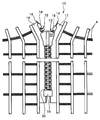
- FIG. 2 is an enlarged plan view of the vicinity of a slide fastener that joins nets of stationary nets.
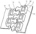
- FIG. 3 is an enlarged perspective view of a part of the fastener stringer in the meshing state shown in FIG.
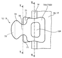
- FIG. 4 is an enlarged plan view of the engagement tooth shown in FIGS. 2 and 3.
- FIG. 5 is a view for explaining the shape of the cross section VV of the meshing neck portion shown in FIG. 4 and the cross-sectional area Sn at the meshing neck portion.
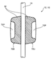
- FIG. 6 is a view for explaining the shape of the leg VI-VI cross section shown in FIG.
- FIG. 7 is a perspective view showing a state in which the service tooth is detached from the fastener stringer due to the breakage in the leg portion of the service tooth.
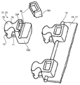
- FIG. 8 is a perspective view showing another embodiment of the engagement tooth attached to the opposite end edge of the fastener tape in the fastener stringer.
- FIG. 9 is a view showing a meshed state in which the engagement teeth in the pair of left and right fastener stringers shown in FIG. 8 are meshed with each other.
- FIG. 10 is a view for explaining the shape of the cross section XX of the meshing neck portion shown in FIG. 9 and the cross-sectional area Sn at the meshing neck portion.
- FIG. 11 is a diagram for explaining the shape of the leg section XI-XI and the sectional area Sf of the leg section shown in FIG.
- FIG. 12 is a cross-sectional view illustrating a state before the repair service tooth is attached to the fastener stringer.
- FIG. 13 is a cross-sectional view illustrating a state where the repair service tooth is attached to the fastener stringer.
- FIG. 14 is a diagram for explaining a damage state that occurs when a strong lateral pulling force is applied to a conventional slide fastener.
- FIG. 1 is a diagram showing a use example in which a slide fastener 10 to which fastener stringers 16 and 17 according to the present invention are applied is applied for joining in a stationary net 2 for fish farming.
- FIG. 2 is an enlarged plan view of the vicinity of the slide fastener 10 that joins the nets 4 of the stationary net 2.
- a plurality of slide fasteners 10 are used for joining the nets 4 constituting the stationary net 2 having a circumference of about 20 m.
- the stationary net 2 shown in FIG. 1 is for aquaculture of tuna and is continuously used for 3 years or more.
- FIG. 1 and FIG. 2 by forming a stationary net 2 by joining a plurality of nets 4 using a slide fastener 10, the net 4 and the stationary net 2 can be easily manufactured, assembled, and disassembled and used. This makes it easy to repair the damaged net 4.
- the slide fastener 10 is composed of a pair of left and right fastener stringers 16 and 17 and a slider 50.
- a plurality of engagement teeth 12 and 13 are attached to the opposing side edges of the fastener tape constituting the pair of left and right fastener stringers 16 and 17 so as to straddle the core portion 14 respectively.
- the embodiment shown in FIG. 2 the embodiment is shown in which the engagement teeth 12 and 13 are attached across the core portion 14 that is thickly extended so as to bulge to the opposite end edge of the fastener tape. Is not limited to the embodiment in which the core portion 14 is formed on the opposite edge of the fastener tape, and can also be applied to a tooth that is attached to a fastener tape that does not include the core portion 14.
- the slider 50 is prevented from falling off and moved to one end (upper end portion in the example shown in FIG. 2) of the service teeth 12 and 13 arranged on the opposite end edges of the fastener stringers 16 and 17.
- An upper stop 18 for limiting the range is connected to each other.
- a box 19 that prevents the slider 50 from falling off and limits the movement range is provided at the other end (the lower end portion in the example shown in FIG. 2) of the tooth 13 that is arranged at one end edge of the fastener stringer 17. It is attached.
- the upper stopper 18 is connected to each of the fastener stringers 16 and 17 one by one, but the box 19 is attached only to the fastener stringer 17 side.
- the other end (the lower end portion in the example shown in FIG. 2) of the engagement tooth 12 row arranged at one end edge of the fastener stringer 16 can be inserted into the insertion portion provided in the box 19.
- a large butterfly stick 30 is connected.
- a resin molded product such as polyacetal can be used as the material for the engagement teeth 12 and 13, the box 19, and the butterfly stick 30.
- the slider 50 When reconnecting the left and right fastener stringers 16 and 17 in the separated state, the slider 50 is first lowered to the lowest position where it abuts the box 19. Then, the butterfly stick 30 attached to one end edge of the fastener stringer 16 is inserted from the left shoulder of the slider 50 shown in FIG. 2 and inserted into the fitting insertion portion of the box 19. Thereafter, the slider 50 is pulled up (moved upward as shown in FIG. 2).
- FIG. 3 is an enlarged perspective view of a part of the fastener stringers 16 and 17 in the meshing state shown in FIG.
- FIG. 4 is an enlarged plan view of the engagement teeth 12 and 13 shown in FIGS. 2 and 3.
- the engagement teeth 12 and 13 are arranged in a row at the opposite end edges of the pair of left and right fastener stringers 16 and 17, respectively.
- a core portion 14 bulging thicker than the fastener tape is extended to the opposite end edge of the fastener tape constituting the pair of left and right fastener stringers 16 and 17.
- the engagement teeth 12 and 13 are attached to the fastener tape in a shape straddling the core portion 14 (a shape that surrounds the core portion 14 and sandwiches the front and back sides).
- the engagement teeth 12 and 13 are provided with leg portions 72U and leg portions 72D (the first and second surfaces of the fastener tape) that are attached to the front and rear surfaces (first and second surfaces of the fastener tape) across the edge of the fastener tape.
- a first leg and a second leg In the state shown in FIGS. 3 and 4, since the first surface of the two surfaces perpendicular to the fastener tape surface of the fastener stringers 16 and 17 is observed, the leg portion 72D on the second surface side is the back surface. I can't see it.
- a meshing neck portion 78 extends from the leg portion 72U and the leg portion 72D toward the mating teeth 13 and 12 on the other side. From the meshing neck portion 78, the meshing head 70 extends further toward the mating tooth 13, 12.
- the meshing neck part 78 is a constricted part formed between the leg parts 72U and 72D and the meshing head part 70.
- the meshing neck portion 78 is a portion into which the mating head portion 70 in which the mating engagement teeth 13 and 12 bulge is inserted during meshing, and the meshing neck portion 78 and the meshing head portion 70 are alternately meshed to form a pair of left and right pairs. It can withstand the lateral pulling force in the direction in which the fastener stringers 16 and 17 are separated from each other.
- two front and back meshing protrusions 71 are extended on both sides of the meshing neck portion 78 in parallel with the fastener tape from the constricted portion of the meshing neck portion 78 of the engagement teeth 12 and 13 to the leg portions 72U and 72D. It is out.
- the dimension in the tape length direction of the front and back meshing protrusions 71 is larger than the dimension in the tape length direction of the leg portions 72U and 72D.
- a front and back meshing recess 73 parallel to the fastener tape is formed at the center of the top of the meshing head 70 (in the thickness direction of the end opposite to the legs 72U and 72D).
- the front and back meshing recess 73 is a portion into which the front and back meshing protrusions 71 of the mating engagement teeth 13 and 12 are fitted when meshing.
- the front and back meshing protrusions 71 of the mating engagement teeth 13 and 12 are fitted in the front and back meshing recesses 73 so that the thrust force applied in the direction perpendicular to the fastener tape surface (thickness direction) With this, it is possible to prevent the engaging teeth 12 and 13 in the meshing state from shifting in the direction perpendicular to the fastener tape surface.
- a concave thin portion 72P that is recessed into a rectangular shape in plan view is formed on a part of the surface of the legs 72U and 72D opposite to the fastener tape surface.
- the purpose of forming the thin-walled portion 72P is that the leg portions 72U and 72D in a cross section passing through the core portion 14 are parallel to the core portion 14 extending on the side edge of the fastener tape and perpendicular to the fastener tape. It is formed to reduce the cross-sectional area.
- FIG. 5 is a view for explaining the shape of the cross section VV of the meshing neck 78 shown in FIG. 4 and the cross-sectional area Sn at the meshing neck 78.
- FIG. 6 is a view for explaining the shape of the VI-VI cross section of the leg portions 72U and 72D shown in FIG. 4 and the cross-sectional area Sf at the leg portions 72U and 72D.
- the cross section of the meshing neck portion 78 of the service teeth 12, 13 is long with respect to the thickness direction of the service teeth 12, 13 (direction perpendicular to the fastener tape surface) and the length of the core portion 14. It has a short, substantially rectangular cross section with respect to the vertical direction.
- Two front and back meshing protrusions 71 extend from both side walls of the meshing neck portion 78 constricted in parallel with the length direction of the core portion 14.
- the minimum cross-sectional area in the meshing neck 78 shown in FIG. 5 is defined as Sn.
- the cross-section of the cross-sectional area Sn may be a cross-section from which the minimum cross-sectional area at the meshing neck 78 can be obtained.
- FIG. 6 shows a cross section of the leg portions 72U and 72D that are parallel to the length direction of the fastener tape and orthogonal to the fastener tape surface and pass through the substantially central portion of the core portion 14.
- the external appearance is represented without making a cross section.
- the cross-sectional shapes of the leg portions 72U and 72D maintain the rigidity of the leg portions 72U and 72D by setting both side portions of the leg portions 72U and 72D in the length direction of the core portion 14 high. be able to. Even when a lateral pulling force is applied to the pair of left and right fastener stringers 16 and 17 in the meshing state, the leg portions 72U and 72D can be opened and the core portion 14 can be prevented from falling off.
- a concave thin-walled portion 72P is formed on a part of the open-side surface of the engagement teeth 12 and 13 on the back side of the portion where the leg portions 72U and 72D are attached to the fastener tape across the core portion 14. It is. By forming the thin portion 72P, the cross-sectional areas of the leg portions 72U and 72D on the surface passing through the core portion 14 can be reduced. As shown in FIG. 2 to FIG. 4 and FIG. 6, a concave thin portion 72P is formed on a part of the open-side surface of the service teeth 12, 13 so that the outer shape of the service teeth 12, 13 is the same as that of the conventional service. By maintaining the same dimensions as the teeth, a standard slider can be used as a slider for meshing and separating the engagement teeth 12 and 13.
- the cross-sectional area Sn can be more reliably engaged. Prior to the neck portion 78, breakage can be generated in the leg portions 72U and 72D having the cross-sectional area Sf.
- the fracture in the tape length direction of the thin portion 72P is made larger than the dimension of the meshing neck portion 78 in the tape length direction. It is possible to make it suitable for the shape.
- the dimension of the leg portions 72U and 72D in the tape length direction is 11.8 mm
- the dimension of the mesh neck portion 78 in the tape length direction is 5.4 mm
- the dimension in the thickness direction from the surface of the leg portions 72U and 72D (the depth of the thin wall portion 72P).
- the dimension in the thickness direction from the fastener tape surface of the leg portions 72U and 72D in the thin portion 72P is formed larger than the thickness dimension).
- the maximum dimension of the leg portions 72U and 72D in the thickness direction from the fastener tape surface is 100%, the depth of the thin portion 72P at that position is less than 45%, and the thickness from the fastener tape surface is The height is preferably 55% or more.
- the cross-sectional area Sf and the cross-sectional area Sn can be calculated by the broken service tooth, or can be calculated by an arbitrary service tooth on the fastener stringers 16 and 17 different from the broken service tooth.
- leg portions 72U and 72D of the service teeth Even if breakage occurs in the leg portions 72U and 72D of the service teeth, since the shapes of the meshing head 70 and the meshing neck 78 are maintained, the meshed state of the pair of left and right fastener stringers 16 and 17 is maintained. In addition, the rupture of the leg portions 72U and 72D of the service teeth makes it impossible to continue using the service teeth, but the service teeth fall off the fastener tape. When repairing is performed, the work of removing the broken service teeth 12 and 13 is unnecessary.
- a concave thin portion 72P is formed on both the leg portion 72U and the leg portion 72D.
- the thin portion 72P is either one of the leg portion 72U and the leg portion 72D.
- the cross-sectional area Sf of one of the leg portion 72U and the leg portion 72D smaller than the cross-sectional area Sn of the meshing neck portion 78, the cross-sectional area Sn is cut before the meshing neck portion 78 of the cross-sectional area Sn. Breakage can be generated in the leg portion 72U or the leg portion 72D having the area Sf. Further, the breaking strength is lower than the breaking strength of the fastener tape.
- FIG. 7 is a perspective view showing a state where the service teeth 12 and 13 are detached from the fastener stringers 16 and 17 due to the breakage in the leg portions 72U of the service teeth 12 and 13.
- FIG. 7 the same code
- FIG. 8 is a perspective view showing another embodiment of the engagement teeth 112 and 113 attached to the opposite end edges of the fastener tape in the fastener stringers 116 and 117.
- FIG. 9 is a diagram showing a meshed state in which the engagement teeth 112 and 113 of the pair of left and right fastener stringers 116 and 117 shown in FIG. 8 are meshed with each other, and a cross section perpendicular to the length direction of the fastener stringers 116 and 117. It is sectional drawing cut
- FIG. 10 is a diagram for explaining the shape of the cross-section XX of the meshing neck portion 78 shown in FIG. 9 and its cross-sectional area Sn.
- FIG. 10 is a diagram for explaining the shape of the cross-section XX of the meshing neck portion 78 shown in FIG. 9 and its cross-sectional area Sn.
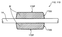
- FIG. 11 is a diagram for explaining the shape of the XI-XI cross section of the leg portions 172U and 172D shown in FIG. 9 and the cross sectional area Sf thereof.
- part which has the same function as the site
- the engagement teeth 112, 113 have leg portions 172 ⁇ / b> U and legs that are attached to the front and back of the fastener tape (first surface and second surface of the fastener tape) across the edge of the fastener tape.
- a portion 172D (first leg and second leg) is provided. In the perspective view shown in FIG. 8, the leg portion 172D on the second surface side is hidden behind the back surface and is not visible.
- the thin portions 172P of the leg portions 712U and 172D of the service teeth 112 and 113 are formed to be thin with respect to the meshing neck portion 78 in one step parallel to the fastener tape.
- the thin portion 172P is parallel to the core portion 14 extending on the side edge of the fastener tape and perpendicular to the fastener tape, and reduces the cross-sectional area of the leg portions 172U and 172D on the plane passing through the core portion 14. This is a part formed for the purpose.
- a slider 150 that brings the service teeth 112 and 113 into an engaged state or a separated state is shown by a broken line in FIG.
- the slider 150 shown in FIG. 9 is the figure which looked at the state which has inserted the service teeth 112 and 113 in a meshing state from the back opening side of the slider 150.
- FIG. In the slider 150 a tooth guide passage for inserting the tooth 112, 113 is formed surrounded by the upper wing piece 52, the lower wing piece 53, and the flange 50F.
- a tape insertion passage for inserting a fastener tape is formed between the flange 50F extending from both end edges of the upper wing piece 52 and the flange 50F extending from both end edges of the lower wing piece 53.
- FIG. 10 is a diagram for explaining the shape of the cross section XX of the meshing neck portion 78 shown in FIG. 9 and the cross-sectional area Sn at the meshing neck portion 78.
- FIG. 11 is a diagram for explaining the shape of the XI-XI cross section of the leg portions 172U and 172D shown in FIG. 9 and the cross-sectional area Sf of the leg portions 172U and 172D.
- the cross section of the meshing neck portion 78 of the service teeth 112, 113 is long with respect to the thickness direction of the service teeth 112, 113 (direction perpendicular to the fastener tape surface), and the length of the core portion 14. It has a short, substantially rectangular cross section with respect to the vertical direction.
- Two front and back meshing protrusions 71 extend from both side walls of the meshing neck portion 78 constricted in parallel with the length direction of the core portion 14.
- the minimum cross-sectional area in the meshing neck 78 shown in FIG. 10 is defined as Sn.
- the cross-sectional area of the surface parallel to the length direction of the fastener tape and orthogonal to the surface of the fastener tape is shown, but the present invention is not limited to the cross-sectional area of this cut surface. Any cross-section that has a minimum cross-sectional area at the meshing neck 78 may be used.
- FIG. 11 shows a cross section of the leg portions 172U and 172D that are parallel to the length direction of the fastener tape and orthogonal to the fastener tape surface and pass through the substantially central portion of the core portion 14.
- the external appearance is represented without making a cross section.
- the open side surfaces of the engagement teeth 112, 113 form a thin portion 172P having a shape thinner than the meshing neck portion 78. It is.
- the cross-sectional areas of the leg portions 172U and 172D on the surface passing through the core portion 14 can be reduced.
- the cross-sectional area Sn can be more reliably engaged. Prior to the neck portion 78, breakage can be generated in the leg portions 172U and 172D of the cross-sectional area Sf.
- FIG. 10 and FIG. 11 an embodiment is shown in which a core portion 14 formed thicker than the fastener tape is extended to the opposite end edges of the pair of left and right fastener tapes.
- the present invention is not limited to the fastener stringers 116 and 117 having the core portion 14 on the tape, and can be applied to a fastener stringer having a flat fastener tape not having the core portion 14.
- the thin portion 172P is formed on both the leg portion 172U and the leg portion 172D is shown, but the thin portion 172P is attached to either the leg portion 172U or the leg portion 172D.
- the thin-walled portion 172P and forming the cross-sectional area Sf of either the leg portion 172U or the leg portion 172D smaller than the cross-sectional area Sn of the meshing neck portion 78, the cross-sectional area Sn is ahead of the meshing neck portion 78.
- a break can be generated at the leg portion 172U or the leg portion 172D having the cross-sectional area Sf.
- FIG. 12 is a view showing a state before the repair service tooth 212 is attached to the fastener stringers 16 and 17, and is a cross-sectional view showing a state cut along a cross section perpendicular to the length direction of the fastener tape. is there.
- FIG. 13 is a cross-sectional view showing a state in which the repair service tooth 212 is attached to the fastener stringers 16 and 17.
- part which has the same function as the site
- the repair service tooth 212 is a service tooth divided into two in the front and back direction. Although the two repair service teeth 212 shown in FIGS. 12 and 13 have the same shape, they can be combined in different shapes.
- the two repair service teeth 212 are sandwiched from the front and back of the fastener tape at predetermined positions of the fastener stringers 16 and 17 using a jig or the like. Position it. Then, a mounting hole is opened in the fastener tape, and the bolt 210 is inserted into the bolt hole 212H of the two repairing service teeth 212 and the opened mounting hole. Then, the nut 211 is fastened from the opposite side, and the two repair service teeth 212 are attached to the fastener tape. In this manner, the fastener stringers 16 and 17 can be repaired easily. This operation can also be performed on a ship with the stationary net 2 pulled up. In addition, metals, such as stainless steel and a copper alloy, can be used as the raw material for the repair service tooth 212.
- fastener stringer is not limited to the use of joining between stationary nets.
Landscapes
- Slide Fasteners (AREA)
Abstract
Description
4 網
10、910 スライドファスナー
12、13、112、113、912、913 務歯
14 芯部
16、17、916、917 ファスナーストリンガー
18 上止具
19 箱体
50、150 スライダー
50F フランジ
52 上翼片
53 下翼片
56 引手支持部
70 噛合頭部
71 表裏噛合突片
72U、72D、172U、172D 脚部
72P、172P 薄肉部
73 表裏噛合凹部
78 噛合首部
210 ボルト
211 ナット
212 補修用務歯
212H ボルト孔
920 破断
921 破断
Sn 務歯の噛合首部における断面積
Sf 務歯の脚部における断面積
Claims (7)
- 左右一対のファスナーテープの対向側縁にそれぞれ複数の務歯(12,13)を取着したファスナーストリンガーにおいて、
前記務歯(12,13)は、前記ファスナーテープ面に垂直な方向の一面を第1面とし他の面を第2面とした場合に、前記ファスナーテープの端縁を跨いで第1面側に取着する第1脚部(72U)と、第2面側に取着する第2脚部(72D)と、前記第1及び第2脚部(72U,72D)から相手側の務歯(13,12)に向けて延出する噛合首部(78)と、当該噛合首部(78)から更に同方向に延出するとともにファスナーテープ長さ方向に膨出する噛合頭部(70)とを有してなり、
前記噛合首部(78)における最小の断面積をSnとし、前記第1及び第2脚部(72U,72D)の少なくとも一方のファスナーテープ幅方向における少なくとも一部の断面であって、ファスナーテープの長さ方向に平行な断面の断面積をSfとした場合に、Sn>Sfの関係を満たすことを特徴とするファスナーストリンガー。 - 請求項1に記載のファスナーストリンガーにおいて、
前記左右一対のファスナーテープの対向端縁に、ファスナーテープよりも厚手に形成した芯部(14)を延設し、
前記務歯(12,13)の第1及び第2脚部(72U,72D)は、前記芯部(14)を跨いで前記ファスナーテープの対向端縁に取着され、
前記断面積Sfは、前記延設されている芯部(14)に平行且つ当該芯部(14)を通る面の断面積であることを特徴とするファスナーストリンガー。 - 請求項2に記載のファスナーストリンガーにおいて、
前記断面積Snと断面積Sfとの間で、0.8×Sn>Sfの関係を満たすことを特徴とするファスナーストリンガー。 - 請求項2又は3のいずれかに記載のファスナーストリンガーにおいて、
前記第1及び第2脚部(72U,72D)の少なくとも一方に、噛合首部(78)の厚さ方向の寸法よりも薄く、かつ前記断面積Sfを減ずる薄肉部を形成したことを特徴とするファスナーストリンガー。 - 請求項4に記載のファスナーストリンガーにおいて、
前記薄肉部(72P)は、前記第1及び第2脚部(72U,72D)の少なくとも一方に、凹形状に形成されてなることを特徴とするファスナーストリンガー。 - 請求項5に記載のファスナーストリンガーにおいて、
前記凹形状の薄肉部(72P)のテープ長さ方向の寸法が、噛合首部(78)のテープ長さ方向の寸法よりも大きく形成されてなることを特徴とするファスナーストリンガー。 - 請求項1に記載のファスナーストリンガーにおいて、
樹脂製の務歯(12,13)列からなるファスナーストリンガー(16,17)の一部で、前記樹脂製の務歯(12,13)列上に、金属製で表裏方向に2分割された補修用務歯(212)を、ファスナーテープを挟み込むようにし、ボルト(210)で螺合してファスナーテープに取着してなることを特徴とするファスナーストリンガー。
Priority Applications (4)
| Application Number | Priority Date | Filing Date | Title |
|---|---|---|---|
| CN200980158779.7A CN102395290B (zh) | 2009-06-03 | 2009-06-03 | 拉链牙链带 |
| PCT/JP2009/060135 WO2010140231A1 (ja) | 2009-06-03 | 2009-06-03 | ファスナーストリンガー |
| JP2011518123A JP5127984B2 (ja) | 2009-06-03 | 2009-06-03 | ファスナーストリンガー |
| TW099106317A TWI446885B (zh) | 2009-06-03 | 2010-03-04 | Chain belt |
Applications Claiming Priority (1)
| Application Number | Priority Date | Filing Date | Title |
|---|---|---|---|
| PCT/JP2009/060135 WO2010140231A1 (ja) | 2009-06-03 | 2009-06-03 | ファスナーストリンガー |
Publications (1)
| Publication Number | Publication Date |
|---|---|
| WO2010140231A1 true WO2010140231A1 (ja) | 2010-12-09 |
Family
ID=43297378
Family Applications (1)
| Application Number | Title | Priority Date | Filing Date |
|---|---|---|---|
| PCT/JP2009/060135 Ceased WO2010140231A1 (ja) | 2009-06-03 | 2009-06-03 | ファスナーストリンガー |
Country Status (4)
| Country | Link |
|---|---|
| JP (1) | JP5127984B2 (ja) |
| CN (1) | CN102395290B (ja) |
| TW (1) | TWI446885B (ja) |
| WO (1) | WO2010140231A1 (ja) |
Cited By (2)
| Publication number | Priority date | Publication date | Assignee | Title |
|---|---|---|---|---|
| WO2015046497A1 (ja) * | 2013-09-30 | 2015-04-02 | Ykk株式会社 | スライドファスナーチェーン及びスライドファスナー |
| JP2023030703A (ja) * | 2021-08-24 | 2023-03-08 | Ykk株式会社 | ファスナーエレメント、ファスナーストリンガー、ファスナーストリンガーの製造方法 |
Families Citing this family (2)
| Publication number | Priority date | Publication date | Assignee | Title |
|---|---|---|---|---|
| WO2019043851A1 (ja) * | 2017-08-30 | 2019-03-07 | Ykk株式会社 | スライドファスナー用エレメント |
| CN113208242A (zh) * | 2021-04-09 | 2021-08-06 | 中铝材料应用研究院有限公司 | 一种海洋工程用全铜链式连接机构及其应用 |
Citations (2)
| Publication number | Priority date | Publication date | Assignee | Title |
|---|---|---|---|---|
| JPS57104906U (ja) * | 1980-12-19 | 1982-06-28 | ||
| JP2009160268A (ja) * | 2008-01-08 | 2009-07-23 | Ykk Corp | スライドファスナー |
Family Cites Families (8)
| Publication number | Priority date | Publication date | Assignee | Title |
|---|---|---|---|---|
| JPS5636272Y2 (ja) * | 1975-11-13 | 1981-08-26 | ||
| US4718150A (en) * | 1980-10-02 | 1988-01-12 | Talon, Inc. | Projection cooling of molded slide fastener elements and product |
| PH21498A (en) * | 1981-10-28 | 1987-11-10 | Yoshida Kogyo Kk | Slide fastener assembly |
| JPH0779815A (ja) * | 1993-09-10 | 1995-03-28 | Ykk Kk | スライドファスナー用テープおよびスライドファスナー |
| JP2000004911A (ja) * | 1998-06-22 | 2000-01-11 | Shinagawa Shoko Kk | スライドファスナー |
| JP3685255B2 (ja) * | 2001-06-18 | 2005-08-17 | Ykk株式会社 | 気密防水用スライドファスナー |
| JP4312676B2 (ja) * | 2004-07-26 | 2009-08-12 | Ykk株式会社 | スライドファスナー用ストリンガー |
| CN2754414Y (zh) * | 2004-11-15 | 2006-02-01 | 陈德宁 | 一种拉链 |
-
2009
- 2009-06-03 WO PCT/JP2009/060135 patent/WO2010140231A1/ja not_active Ceased
- 2009-06-03 CN CN200980158779.7A patent/CN102395290B/zh active Active
- 2009-06-03 JP JP2011518123A patent/JP5127984B2/ja active Active
-
2010
- 2010-03-04 TW TW099106317A patent/TWI446885B/zh not_active IP Right Cessation
Patent Citations (2)
| Publication number | Priority date | Publication date | Assignee | Title |
|---|---|---|---|---|
| JPS57104906U (ja) * | 1980-12-19 | 1982-06-28 | ||
| JP2009160268A (ja) * | 2008-01-08 | 2009-07-23 | Ykk Corp | スライドファスナー |
Cited By (5)
| Publication number | Priority date | Publication date | Assignee | Title |
|---|---|---|---|---|
| WO2015046497A1 (ja) * | 2013-09-30 | 2015-04-02 | Ykk株式会社 | スライドファスナーチェーン及びスライドファスナー |
| JPWO2015046497A1 (ja) * | 2013-09-30 | 2017-03-09 | Ykk株式会社 | スライドファスナーチェーン及びスライドファスナー |
| US10306954B2 (en) | 2013-09-30 | 2019-06-04 | Ykk Corporation | Slide fastener chain and slide fastener |
| JP2023030703A (ja) * | 2021-08-24 | 2023-03-08 | Ykk株式会社 | ファスナーエレメント、ファスナーストリンガー、ファスナーストリンガーの製造方法 |
| JP7695152B2 (ja) | 2021-08-24 | 2025-06-18 | Ykk株式会社 | ファスナーエレメント、ファスナーストリンガー、ファスナーストリンガーの製造方法 |
Also Published As
| Publication number | Publication date |
|---|---|
| CN102395290A (zh) | 2012-03-28 |
| CN102395290B (zh) | 2014-10-01 |
| TWI446885B (zh) | 2014-08-01 |
| JPWO2010140231A1 (ja) | 2012-11-15 |
| TW201102013A (en) | 2011-01-16 |
| JP5127984B2 (ja) | 2013-01-23 |
Similar Documents
| Publication | Publication Date | Title |
|---|---|---|
| JP5127984B2 (ja) | ファスナーストリンガー | |
| JPWO2011070678A1 (ja) | ファスナーストリンガー及びスライドファスナー、並びにファスナーストリンガーの補修方法 | |
| JPWO2012164682A1 (ja) | 開離嵌挿具付きスライドファスナー及び射出成形用金型 | |
| JPWO2010113275A1 (ja) | スライドファスナー用スライダー並びにクイックオープン式スライドファスナー | |
| CN107950170B (zh) | 刀具组件、组装刀具组件的方法、用于刀具组件的刀护罩 | |
| TWI754635B (zh) | 拉鏈用金屬單件式滑件及拉件 | |
| DE10352768B4 (de) | Verbinder und Verbinderanordnung | |
| JP7084908B2 (ja) | スライドファスナのための金属一体スライドおよび引手 | |
| DE112012001673B4 (de) | Verfahren zum Herstellen einer Reifenvulkanisierform und Reifenvulkanisierform | |
| DE102007030014A1 (de) | Verbinder, Verbinderanordnung und Verbindungsverfahren | |
| JP3188025U (ja) | 開離嵌挿具及び隠しスライドファスナー | |
| JP2018019648A (ja) | 釣糸の留め具 | |
| JP7715927B2 (ja) | スライドファスナー用ファスナーエレメント及びスライドファスナー | |
| JP5707060B2 (ja) | 樹脂成形品 | |
| DE102008025082B3 (de) | Werkzeug zum Formen von Werkstücken | |
| JP2005009644A (ja) | 締結機構、締結機構の分解方法および締結機構の締結・分解工具 | |
| KR20110013645A (ko) | 낚시용 찌고무 | |
| EP3672888A1 (de) | Trennelement zur unterteilung des innenraumes eines draht-korbes | |
| CN104000352B (zh) | 可拆卸的自锁式拉链头 | |
| EP2875886B1 (de) | Spiralbohrer und Verfahren zu dessen Herstellung | |
| CN210676842U (zh) | 浇铸系统 | |
| DE102012200948A1 (de) | Gehäuse für Fluide | |
| DE20306830U1 (de) | Schmuckstück mit einem lösbar befestigten Zierteil | |
| DE102006023514A1 (de) | Plattengepasster, aus Harz geformter Gegenstand und Verfahren zum Formen desselben | |
| CN218362008U (zh) | 一种发动机缸体模具油道铸销结构 |
Legal Events
| Date | Code | Title | Description |
|---|---|---|---|
| WWE | Wipo information: entry into national phase |
Ref document number: 200980158779.7 Country of ref document: CN |
|
| 121 | Ep: the epo has been informed by wipo that ep was designated in this application |
Ref document number: 09845516 Country of ref document: EP Kind code of ref document: A1 |
|
| WWE | Wipo information: entry into national phase |
Ref document number: 2011518123 Country of ref document: JP |
|
| NENP | Non-entry into the national phase |
Ref country code: DE |
|
| 122 | Ep: pct application non-entry in european phase |
Ref document number: 09845516 Country of ref document: EP Kind code of ref document: A1 |