WO2010140208A1 - 回転電機 - Google Patents
回転電機 Download PDFInfo
- Publication number
- WO2010140208A1 WO2010140208A1 PCT/JP2009/059991 JP2009059991W WO2010140208A1 WO 2010140208 A1 WO2010140208 A1 WO 2010140208A1 JP 2009059991 W JP2009059991 W JP 2009059991W WO 2010140208 A1 WO2010140208 A1 WO 2010140208A1
- Authority
- WO
- WIPO (PCT)
- Prior art keywords
- rotor
- coil
- teeth
- rotating electrical
- electrical machine
- Prior art date
- Legal status (The legal status is an assumption and is not a legal conclusion. Google has not performed a legal analysis and makes no representation as to the accuracy of the status listed.)
- Ceased
Links
Images







Classifications
-
- H—ELECTRICITY
- H02—GENERATION; CONVERSION OR DISTRIBUTION OF ELECTRIC POWER
- H02K—DYNAMO-ELECTRIC MACHINES
- H02K1/00—Details of the magnetic circuit
- H02K1/06—Details of the magnetic circuit characterised by the shape, form or construction
- H02K1/22—Rotating parts of the magnetic circuit
- H02K1/24—Rotor cores with salient poles ; Variable reluctance rotors
-
- H—ELECTRICITY
- H02—GENERATION; CONVERSION OR DISTRIBUTION OF ELECTRIC POWER
- H02K—DYNAMO-ELECTRIC MACHINES
- H02K19/00—Synchronous motors or generators
- H02K19/02—Synchronous motors
- H02K19/10—Synchronous motors for multi-phase current
- H02K19/12—Synchronous motors for multi-phase current characterised by the arrangement of exciting windings, e.g. for self-excitation, compounding or pole-changing
-
- H—ELECTRICITY
- H02—GENERATION; CONVERSION OR DISTRIBUTION OF ELECTRIC POWER
- H02K—DYNAMO-ELECTRIC MACHINES
- H02K19/00—Synchronous motors or generators
- H02K19/16—Synchronous generators
- H02K19/26—Synchronous generators characterised by the arrangement of exciting windings
- H02K19/28—Synchronous generators characterised by the arrangement of exciting windings for self-excitation
-
- H—ELECTRICITY
- H02—GENERATION; CONVERSION OR DISTRIBUTION OF ELECTRIC POWER
- H02K—DYNAMO-ELECTRIC MACHINES
- H02K3/00—Details of windings
- H02K3/46—Fastening of windings on the stator or rotor structure
- H02K3/52—Fastening salient pole windings or connections thereto
- H02K3/527—Fastening salient pole windings or connections thereto applicable to rotors only
Definitions
- the present invention relates to a rotating electrical machine, and more particularly to a rotating electrical machine with improved output.
- Patent Document 1 a field winding type synchronous machine described in Japanese Unexamined Patent Publication No. 2007-185082 (Patent Document 1) includes a rotor provided with a rotor coil and a stator provided with a stator coil. A rectifier circuit is provided in the rotor coil, and a field flux current in a desired direction is formed in the rotor coil by rectifying the alternating current.
- the rotating electrical machine described in Japanese Patent Application Laid-Open No. 2008-086161 includes a stator and a rotor, the stator is provided with a stator coil, and the rotor is provided with a rotor coil. ing.
- the stator coil is supplied with an armature current obtained by superimposing a rotor exciting current on a synchronous current.
- an induced voltage of the rotor coil is generated using spatial harmonics from the stator.
- a sufficient dielectric voltage cannot be generated in the rotor coil.
- the present invention has been made in view of the above-described problems, and an object thereof is to provide a rotating electrical machine capable of obtaining a sufficient induced voltage.
- a rotating electrical machine includes an annular rotor core having a plurality of rotor teeth formed on a peripheral surface thereof, a rotor coil mounted on the rotor teeth, and a rotor provided rotatably and opposed to the rotor. And a stator disposed on the surface.
- the difference between the outermost diameter of the rotor core and the outermost diameter of the rotor coil is 0% or more and 4% or less of the outermost diameter of the rotor core.
- a fixing member for fixing the rotor coil to the rotor core is further provided, and the fixing member is made of a nonmagnetic material.
- the fixing member includes a first locking member, a second locking member, and a coil circumferential surface fixing portion
- the first locking member is one of the rotor coils arranged in the central axis direction of the rotor core.
- the second locking member engages with the other end of the rotor coil arranged in the direction of the central axis of the rotor core, and the coil peripheral surface fixing portion covers the peripheral surface of the rotor.
- the difference between the outermost diameter of the rotor core and the outermost diameter of the rotor coil is 1.3% or more and 4% or less of the outermost diameter of the rotor core.
- the rotor teeth include a plurality of first rotor teeth and second rotor teeth alternately provided on the peripheral surface of the rotor core, and the rotor coils include first rotor coils mounted on the first rotor teeth, And a second rotor coil mounted on each second rotor tooth.
- the first rotor coils are connected to each other, the second rotor coils are connected to each other, the flow direction of the current flowing in the first rotor coil is defined, and the first magnetic pole is formed on the end face of the first rotor teeth.
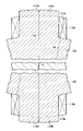
- FIG. 2 is a cross-sectional view showing a rotor tooth 112A and a rotor tooth 112B located on the opposite side of the rotation center line O from the rotor tooth 112A.
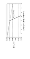
- FIG. 6 is a graph showing the relationship between ⁇ (R1-R2) / R1 ⁇ ⁇ 100 (%) and the maximum torque of rotating electrical machine 100. It is a figure which shows a fundamental wave magnetic flux component and a double long wave magnetic flux component among the spatial harmonics produced between the rotor 110 and the stator 130.
- FIG. FIG. 3 is a development view in which a part of a rotor 110 is developed.
- FIG. 6 is a development view of the rotor 110 showing a state after a half cycle of the double long wave magnetic flux P2 from the state shown in FIG.
- FIG. 7 is a development view of the rotor 110 showing a state in which a predetermined period has elapsed from the state shown in FIGS.
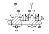
- FIG. 8 is a development view of the rotor 110 showing the flow of magnetic flux in the state shown in FIG. 7. It is sectional drawing which shows the state after 1/2 period of the double long wave magnetic flux P2 from the state shown in FIG.
- FIG. 10 is a development view of the rotor 110 showing the flow of magnetic flux in the state shown in FIG. 9.
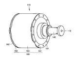
- 2 is a perspective view of a rotor 110.
- FIG. 2 is an exploded perspective view of a rotor 110.
- FIG. 12 is a perspective view showing the rotor 110 in a state where the peripheral surface fixing member 163 and the flange members 161 and 162 are removed from the state shown in FIG. 11. It is a perspective view of the rotor 110 which shows the state which mounted
- FIG. 2 is a cross-sectional view of a rotor 110.
- FIG. 1 is a cross-sectional view schematically showing a rotating electrical machine according to the present invention.
- the rotating electrical machine 100 is fixed to a rotating shaft 140 and is formed in an annular shape so as to surround the rotor 110 and a rotor 110 that is rotatably provided around a rotation center line O. And a stator 130.
- the inner peripheral surface of the stator 130 faces the outer peripheral surface of the rotor 110, and the inner peripheral surface of the stator 130 and the outer peripheral surface of the rotor 110 are slightly separated from each other.
- the stator 130 includes a stator core 150 formed in an annular shape and a stator coil 152 attached to the stator core 150.
- the stator core 150 includes a stator yoke portion 153 formed in an annular shape and a plurality of stator teeth 151 formed on the inner peripheral surface of the stator yoke portion 153 at intervals.
- the stator coil 152 is wound around each stator tooth 151.
- the rotating electrical machine 100 shown in FIG. 1 is a concentrated winding rotating electrical machine.
- the stator coil 152 is a three-phase coil including a U-phase coil, a V-phase coil, and a W-phase coil.
- the rotor 110 includes a rotor core 111 formed in an annular shape, and rotor coils 113 and 123 attached to the rotor core 111.
- the rotor core 111 includes a rotor yoke portion 109 formed in an annular shape and a plurality of rotor teeth 112 and 122 formed on the outer peripheral surface of the rotor yoke portion 109 at intervals.
- a rotor coil 113 is wound around each rotor tooth 112, and a rotor coil 123 is attached to each rotor tooth 122.
- a plurality of rotor teeth 112 and rotor coils 113 are provided, and the rotor coils 113 are connected to each other in series.
- the rotor coils 113 are short-circuited via a diode (rectifier) 114.
- a plurality of rotor teeth 122 and rotor coils 123 are provided, and the rotor coils 123 are connected to each other in series.
- the rotor coils 123 are short-circuited via a diode (rectifier) 124.
- the direction of current flowing through the rotor coil 113 is defined by the diode 114.
- the direction of current flowing through the rotor coil 123 is defined by the diode 124.
- current flows in a direction in which the outer peripheral end surface of the rotor tooth 122 is magnetized by the N magnetic pole (first magnetic pole), while no current flows in a direction in which the outer peripheral end surface of the rotor tooth 122 is magnetized by the S magnetic pole.
- the rotating electrical machine 100 is provided with 12 rotor teeth and 18 stator teeth.
- FIG. 2 is a cross-sectional view showing the rotor teeth 112A and the rotor teeth 112B located on the opposite side of the rotation center line O from the rotor teeth 112A.
- the rotor teeth 112A and the rotor teeth 112B are arranged symmetrically about the rotation center line O.
- the rotor coil 113A is attached to the peripheral surface of the rotor teeth 112A, and the rotor coil 113B is attached to the rotor teeth 112B.
- An arc-shaped radial end surface 115A is formed on a portion of the peripheral surface of the rotor teeth 112A located on the radially outer side.
- an arcuate radial end surface 115B is formed on a portion of the peripheral surface of the rotor teeth 112B located on the radially outer side.
- the distance between the radial end face 115A and the radial end face 115B is taken as the rotor core outermost diameter R1 along the rotation center line O, and the distance between the coil end face 117A and the coil end face 117B is taken along the rotation center line O.
- the outermost diameter R2 of the rotor coil is a diameter of a virtual circle that passes through the radial end face 115A and the radial end face 115B and is centered on the rotation center line O.
- the outermost diameter R2 of the rotor coil is This is the diameter of an imaginary circle that passes through the outermost portion of the end face 117A and the coil end face 117B and has the rotation center line O as the center.
- FIG. 3 is a graph showing the relationship between ⁇ (R1-R2) / R1 ⁇ ⁇ 100 (%) and the maximum torque of the rotating electrical machine 100.
- FIG. 3 shows an analysis result using electromagnetic field analysis software JMAG (registered trademark).
- ⁇ (R1-R2) / R1 ⁇ ⁇ 100 (%) is set to be 0% or more and 4% or less. Thereby, the output of the rotary electric machine 100 can be increased.
- the output of the rotating electrical machine 100 is high when ⁇ (R1-R2) / R1 ⁇ ⁇ 100 (%) is in the range of 0% to 1.3%. Therefore, as an example of a more preferable range, the positions of the rotor coils 113A and 113B are set so that ⁇ (R1-R2) / R1 ⁇ ⁇ 100 (%) is 0% or more and 1.3% or less.
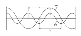
- FIG. 4 is a diagram showing a fundamental wave magnetic flux component and a double wave magnetic flux component among the spatial harmonics generated between the rotor 110 and the stator 130.
- FIG. 5 is a developed view in which a part of the rotor 110 is developed.
- FIG. 5 shows an initial state in which the rotating electrical machine 100 starts to be driven.
- a virtual axis extending in the radial direction of the rotor 110 passing through the central portion in the circumferential direction of the radial end surface 115 of the rotor tooth 112 is defined as a circumferential center line 116, and the circumferential center of the radial end surface 125 of the rotor tooth 122 is further defined.
- a virtual axis extending through the portion in the radial direction of the rotor 110 is defined as a circumferential center line 126.
- a distance between the circumferential center line 116 and the circumferential center line 126 is defined as a distance L between teeth.
- the half wavelength of the fundamental wave magnetic flux P1 is the distance L between teeth, and all the wavelengths of the double long wave magnetic flux P2 are the distance L between teeth.
- the fundamental wave magnetic flux P1 enters the rotor 110 from one of the radial end face 115 and the radial end face 125 and is radiated outward from the other of the radial end face 115 and the radial end face 125.
- the double long wave magnetic flux P2 enters the rotor 110 from the radial end face 115, it also enters the rotor 110 also from the radial end face 125, as shown in FIG. For this reason, the double long wave magnetic flux P2 entering from the radial end face 115 and the double long wave magnetic flux P2 entering from the radial end face 125 repel each other.
- the double long wave magnetic flux P ⁇ b> 2 leaks to the outside from the side surfaces of the rotor teeth 112 and the rotor teeth 122. Then, it intersects with the rotor coil 113 and the rotor coil 123 attached to each of the rotor teeth 112 and the rotor teeth 122.
- FIG. 6 is a development view of the rotor 110 showing a state after a half cycle of the double wave magnetic flux P2 from the state shown in FIG.
- double long wave magnetic flux P ⁇ b> 2 intersects with each rotor coil 113 and rotor coil 123 from the outside, and enters each rotor tooth 112 and rotor tooth 122 from the side surface of each rotor tooth 112 and rotor tooth 122. It is out.
- the double long wave magnetic fluxes P2 repel each other and are radiated to the outside from the radial end face 115 of the rotor teeth 112 and the radial end face 125 of the rotor teeth 122.
- the double long wave magnetic flux P2 intersects each rotor coil 113 and the rotor coil 123, and the intersecting direction and the amount of magnetic flux change with the passage of time.
- FIG. 7 is a development view of the rotor 110 showing a state in which a predetermined period has elapsed from the state shown in FIGS. 5 and 6.
- the double long wave magnetic flux P ⁇ b> 2 enters the rotor teeth 112 from the radial end face 115, exits from the side face of the rotor teeth 112, and intersects the rotor coil 113.
- a dielectric voltage is generated in the rotor coil 113.
- An induced current flows in the rotor coil 113, and the induced current flows in the rotor coil 113 so that the radial end surface 115 of the rotor teeth 112 is magnetized by the S magnetic pole (first magnetic pole).
- the rotor coil 113 is short-circuited via the diode 114, and the diode 114 has a current flowing in the rotor coil 113 so that the radial end face 115 is magnetized by the S magnetic pole as described above. Allowed.
- the magnetic flux amount of the double long wave magnetic flux P ⁇ b> 2 intersecting with the rotor coil 123 also fluctuates, and an induced voltage is also generated in the rotor coil 123.
- An induced voltage is generated in the rotor coil 123 so that the radial end face 125 of the rotor tooth 122 is magnetized by the S magnetic pole.
- the diode 124 connected to the rotor coil 123 prevents the current from flowing through the rotor coil 123 so that the radial end face 125 is magnetized by the S magnetic pole. For this reason, no current flows through the rotor coil 123.
- the fundamental wave magnetic flux P1 but also the double long wave magnetic flux P2 can be used to generate a dielectric current in the rotor coil 113, and the drive efficiency of the rotating electrical machine 100 is improved.
- FIG. 9 is a cross-sectional view showing a state after a half cycle of the double wave magnetic flux P2 from the state shown in FIG.
- the magnetic flux amount of the double long wave magnetic flux P ⁇ b> 2 that intersects the rotor coil 123 and enters the rotor teeth 122 from the side surface of the rotor teeth 122 varies.
- an induced voltage is generated in the rotor coil 123, and an induced current flows in the rotor coil 123 so that the radial end face 125 of the rotor tooth 122 is magnetized with N magnetic poles.
- the diode 124 connected to the rotor coil 123 allows current to flow through the rotor coil 123 so that the radial end face 125 is magnetized as an N magnetic pole (second magnetic pole).
- a similar induced voltage is also generated in the rotor coil 113 attached to the rotor teeth 112.
- This induced voltage causes an induced current to flow in the rotor coil 113 so that the radial end face 115 of the rotor tooth 112 is magnetized with N magnetic poles.
- the diode 114 suppresses the current from flowing through the rotor coil 113 so that the radial end face 115 is magnetized with N magnetic poles. For this reason, no induced current is generated in the rotor coil 113.
- the double wave magnetic flux P2 and the magnetic flux 201 enter the rotor yoke portion 109 from the rotor teeth 112, and then enter the rotor teeth 122.
- the double long wave magnetic flux P ⁇ b> 2 and the magnetic flux 201 go out from the radial end face 125 of the rotor tooth 122.
- the fundamental wave magnetic flux P1 but also the double wave magnetic flux P2 can be used to generate a dielectric current in the rotor coil 123, so that the drive efficiency of the rotating electrical machine 100 is improved.
- FIG. 11 is a perspective view of the rotor 110
- FIG. 12 is an exploded perspective view of the rotor 110.
- the rotor 110 includes a rotor core 111 and rotor coils 113 and 123 attached to rotor teeth 112 and 122 formed on the rotor core 111. It is fixed to the rotor teeth 112 and 113 by a fixing member 160.
- the fixing member 160 is made of a nonmagnetic material and is made of a material having a high specific resistance.
- the fixing member 160 includes a flange member 161, a flange member 162, and a peripheral surface fixing member 163.
- the flange member 161 is attached to one end face of the rotor core 111 arranged in the direction of the rotation center line O, and the flange member 162 is attached to the other end face of the rotor core 111.
- the flange member 161 includes a top plate portion 170 in which a through hole into which the rotary shaft 140 is inserted is formed, and a peripheral wall portion 171 that hangs down from a peripheral portion of the top plate portion 170.
- the flange member 162 also includes a top plate portion 172 in which a through hole into which the rotary shaft 140 is inserted is formed, and a peripheral wall portion 173 formed so as to hang from the peripheral edge portion of the top plate portion 172. .
- FIG. 13 is a perspective view showing the rotor 110 in a state in which the peripheral surface fixing member 163 and the flange members 161 and 162 are removed from the state shown in FIG.
- a rotor coil 113 is attached to each rotor tooth 112, and a rotor coil 123 is attached to the rotor tooth 122.
- the rotor coil 113 includes a coil end portion 131 and a coil end portion 133 that are curved in an arc shape, and a middle abdomen portion 132 located between the coil end portion 131 and the coil end portion 133.
- the rotor coil 123 includes a coil end part 134 that is curved in an arc shape, a coil end part 136, and a middle part 135 that is positioned between the coil end part 134 and the coil end part 136.
- the coil end portion 131 and the coil end portion 133 of the rotor coil 113 are arranged in the direction of the rotation center line O. Further, in a state where the rotor teeth 122 are mounted, the coil end portion 134 and the coil end portion 136 of the rotor coil 123 are arranged in the direction of the rotation center line O.
- the coil end portions 133 and 136 of the rotor coils 113 and 123 are arranged in an annular shape around the rotation center line O, and the other coil end portions 131 and 134 are also arranged in an annular shape around the rotation center line O. Arranged.
- FIG. 14 is a perspective view of the rotor 110 showing a state in which the flange member 161 and the flange member 162 are attached to the state shown in FIG.
- the flange member 161 is attached to one end of the rotor core 111 arranged in the direction of the rotation center line O.
- the peripheral wall portion 171 of the flange member 161 engages with the coil end portion 133 and the coil end portion 136 that are annularly arranged, and the rotor coil 113 and the rotor coil 123 are fixed to the rotor core 111.
- the flange member 162 is attached to the other end portion of the rotor core 111 arranged in the direction of the rotation center line O, and the coil end portion 131 and the coil end portion 134 in which the peripheral wall portion 173 of the flange member 162 is arranged in an annular shape.
- the rotor coil 113 and the rotor coil 123 are fixed to the rotor core 111. This prevents the rotor coil 113 and the rotor coil 123 from falling off.
- FIG. 15 is a cross-sectional view of the rotor 110.
- a support portion 174 is formed on the top plate portion 172 of the flange member 161.
- the support portion 174 is located on the radially inner side with respect to the peripheral wall portion 171.
- the peripheral wall portion 171 supports the outer surface of the coil end portions 133, 136, and the support portion 174 The inner side surfaces of the coil end portions 133 and 136 are supported.
- a support portion 175 is formed on the top plate portion 172 of the flange member 162 inside the peripheral wall portion 173.
- the flange member 162 is attached to the other end of the rotor core 111, so that the peripheral wall portion 173 supports the outer surface of the coil end portion 134, and the support portion 175 supports the inner surface of the coil end portion 131.
- the rotor coils 113 and 123 are accurately positioned by the peripheral wall portions 171 and 173 and the support portions 174 and 175.
- the flange member 161 and the flange member 162 are positioned by bolts (positioning members) 176.
- a screw hole 180 that penetrates the support portion 175 is formed in the flange member 162, and a through hole 181 is also formed in the rotor core 111.
- a screw hole 182 is formed in the support portion 174.
- the bolt 176 is inserted into the screw hole 180 and the through hole 181, and is screwed with a screw portion formed on the inner peripheral surface of the screw hole 182.
- a plurality of such bolts 176 and the like are provided in the circumferential direction of the rotor core 111, and the flange member 161 and the flange member 162 are accurately positioned.
- the rotor coil 113 and the rotor coil 123 are positioned so that ⁇ (R1-R2) / R1 ⁇ ⁇ 100 (%) is within the range of 1.3% to 4%. ing.
- the rotor coils 113 and 123 are positioned on the radially inward side with respect to the radial end surfaces 115 and 125 of the rotor teeth 112 and the rotor teeth 122.
- the peripheral surface fixing member 163 is provided so as to cover the outer peripheral surface of the rotor 110, and the rotor coil 113 and the rotor coil 123 are prevented from dropping from the rotor teeth 112 and the rotor teeth 122. is doing.
- the peripheral surface fixing member 163 is made of carbon fiber, for example. By configuring the peripheral surface fixing member 163 with the carbon fiber, the mass of the peripheral surface fixing member 163 can be suppressed low, the strength can be increased, and the rotor coil 113 and the rotor teeth 122 can be prevented from falling off. Can do.
- the present invention can be applied to a rotating electrical machine, and is particularly suitable as a rotating electrical machine mounted on a vehicle.
Landscapes
- Engineering & Computer Science (AREA)
- Power Engineering (AREA)
- Synchronous Machinery (AREA)
- Iron Core Of Rotating Electric Machines (AREA)
Abstract
回転電機は、周面に複数のロータティース(112)が形成された環状のロータコア(111)と、ロータティース(112)に装着されたロータコイル(113)とを含み、回転可能に設けられたロータ(110)と、ロータと対向するように配置されたステータ(130)とを備え、ロータコア(111)の最外径(R1)とロータコイルの最外径(R2)との差が、ロータコアの最外径(R1)の0%以上4%以下とされる。
Description
本発明は、回転電機に関し、特に、出力の向上が図られた回転電機に関する。
従来から各種の回転電機が提案されている。たとえば、特開2007-185082号公報(特許文献1)に記載された界磁巻線型同期機は、ロータコイルが設けられたロータと、ステータコイルが設けられたステータとを備えている。そして、ロータコイルに整流回路が設けられており、交流電流を整流することで、ロータコイルに所望方向の界磁束電流を形成している。
さらに、特開2008-086161号公報(特許文献2)に記載された回転電機は、ステータとロータとを備え、ステータには、ステータコイルが設けられており、ロータには、ロータコイルが設けられている。そして、ステータコイルには、同期電流にロータ励磁用電流を重畳させた電機子電流が供給されている。
上記のような回転電機においては、ステータからの空間高調波を利用してロータコイルの誘起電圧を発生させている。そして、ロータコイルの端面とステータとの間の距離が広がると、ロータコイルに十分な誘電電圧を発生させることができなくなる。
しかし、上記従来の回転電機においては、ロータコイルとステータとの間の距離については何等記載も示唆もされていない。
本発明は、上記のような課題に鑑みてなされたものであって、その目的は、十分な誘起電圧を得ることができる回転電機を提供することである。
本発明に係る回転電機は、周面に複数のロータティースが形成された環状のロータコアと、ロータティースに装着されたロータコイルとを含み、回転可能に設けられたロータと、ロータと対向するように配置されたステータとを備える。そして、上記ロータコアの最外径とロータコイルの最外径との差が、ロータコアの最外径の0%以上4%以下とされる。
好ましくは、上記ロータコイルをロータコアに固定する固定部材をさらに備え、固定部材は、非磁性材料から形成される。
好ましくは、上記固定部材は、第1係止部材と、第2係止部材と、コイル周面固定部とを含み、第1係止部材は、ロータコアの中心軸線方向に配列するロータコイルの一方の端部と係合し、第2係止部材は、ロータコアの中心軸線方向に配列するロータコイルの他方の端部と係合し、コイル周面固定部は、ロータの周面を覆うように設けられる。
好ましくは、上記ロータコアの最外径とロータコイルの最外径との差が、ロータコアの最外径の1.3%以上4%以下とされる。
好ましくは、上記コイル周面固定部は、カーボンファイバによって形成される。好ましくは、上記ロータコアの最外径とロータコイルの最外径との差が、ロータコアの最外径の1.3%以下とされる。
好ましくは、上記ロータティースは、ロータコアの周面に交互に設けられた第1ロータティースおよび第2ロータティースを複数含み、ロータコイルは、各第1ロータティースに装着された第1ロータコイルと、各第2ロータティースに装着された第2ロータコイルとを含む。そして、上記第1ロータコイル同士は、互いに接続され、第2ロータコイル同士は互いに接続され、第1ロータコイル内を流れる電流の流通方向を規定し、第1ロータティースの端面に第1磁極の磁気を帯びさせる第1整流器と、第2ロータコイル内を流れる電流の流通方向を規定し、第2ロータティースの端面に第2磁極の磁気を帯びさせる第2整流器とをさらに備える。
本発明に係る回転電機によれば、十分な誘起電圧を得ることができる、
図1から図15を用いて、本発明に係る回転電機について説明する。
図1は、本発明に係る回転電機を模式的に示す断面図である。この図1に示すように、回転電機100は、回転シャフト140に固定され、回転中心線Oを中心に回転可能に設けられたロータ110と、このロータ110の周囲を取り囲むように環状に形成されたステータ130とを備えている。
図1は、本発明に係る回転電機を模式的に示す断面図である。この図1に示すように、回転電機100は、回転シャフト140に固定され、回転中心線Oを中心に回転可能に設けられたロータ110と、このロータ110の周囲を取り囲むように環状に形成されたステータ130とを備えている。
ステータ130の内周面は、ロータ110の外周面と対向しており、ステータ130の内周面とロータ110の外周面とは僅かに離れている。
ステータ130は、環状に形成されたステータコア150と、このステータコア150に装着されたステータコイル152とを備えている。
ステータコア150は、環状に形成されたステータヨーク部153と、ステータヨーク部153の内周面に間隔を隔てて形成された複数のステータティース151とを備えている。そして、ステータコイル152は、各ステータティース151に巻回されている。このように、この図1に示す回転電機100は集中巻型の回転電機である。
そして、ステータコイル152は、U相コイルと、V相コイルと、W相コイルとを含み、3相コイルとされている。
ロータ110は、環状に形成されたロータコア111と、このロータコア111に装着されたロータコイル113,123とを備えている。
ロータコア111は、環状に形成されたロータヨーク部109と、このロータヨーク部109の外周面に間隔を隔てて形成された複数のロータティース112,122とを備えている。
そして、各ロータティース112には、ロータコイル113が巻回されており、各ロータティース122にはロータコイル123が装着されている。ロータティース112およびロータコイル113は、複数設けられており、各ロータコイル113同士は互いに直列に接続されている。なお、ロータコイル113同士は、ダイオード(整流器)114を介して短絡されている。そして、ロータティース122およびロータコイル123は、複数設けられており、各ロータコイル123同士は互いに直列に接続されている。そして、ロータコイル123同士は、ダイオード(整流器)124を介して短絡されている。
そして、ロータコイル113を流れる電流方向は、ダイオード114によって規定されている。その結果、ロータティース112の外周端面がS磁極(第2磁極)の磁気を帯びる方向に電流がロータコイル113内を流れる一方で、ロータティース112の外周端面がN磁極の磁気を帯びる方向に電流は流れない。
また、ロータコイル123を流れる電流方向は、ダイオード124によって規定されている。その結果、ロータティース122の外周端面がN磁極(第1磁極)の磁気を帯びる方向に電流が流れる一方で、ロータティース122の外周端面がS磁極の磁気を帯びる方向に電流は流れない。
なお、本実施の形態に係る回転電機100は、ロータティースは、12個、ステータティースは、18個、設けられている。
図2は、ロータティース112Aと、回転中心線Oに対してロータティース112Aと反対側に位置するロータティース112Bとを示す断面図である。
この図2に示すように、ロータティース112Aとロータティース112Bとは、回転中心線Oを中心に対称的に配置されている。
ロータティース112Aの周面には、ロータコイル113Aが装着されており、ロータティース112Bには、ロータコイル113Bが装着されている。
ロータティース112Aの周面のうち径方向外方側に位置する部分には、円弧状の径方向端面115Aが形成されている。同様に、ロータティース112Bの周面のうち径方向外方側に位置する部分には、円弧状の径方向端面115Bが形成されている。
そして、回転中心線Oをとおり、径方向端面115Aと径方向端面115Bとの間の距離をロータコア最外径R1とし、回転中心線Oをとおり、コイル端面117Aとコイル端面117Bとの間の距離をロータコイル最外径R2とする。さらに、具体的には、ロータコア最外径R1は、径方向端面115Aおよび径方向端面115Bをとおり、回転中心線Oを中心とする仮想円の直径であり、ロータコイル最外径R2は、コイル端面117Aおよびコイル端面117Bの最も外側に位置する部分をとおり、回転中心線Oを中心とする仮想円の直径である。
図3は、{(R1-R2)/R1}×100(%)と、回転電機100の最大トルクとの関係を示すグラフである。
この図3において、横軸は、{(R1-R2)/R1}×100(%)を示し、縦軸は、回転電機100の最大トルクを示す。なお、図3は、電磁界解析ソフトウェアJMAG(登録商標)を用いた解析結果である。
この図3に示すように、{(R1-R2)/R1}×100(%)が4%より大きくなると、急激に回転電機100の最大トルクが小さくなることが分かる。その一方で、{(R1-R2)/R1}×100(%)が0%以上4%以下の範囲では、回転電機100の出力トルクが大きいことが分かる。
そこで、本実施の形態に係る回転電機100においては、{(R1-R2)/R1}×100(%)が0%以上4%以下となるように設定している。これにより、回転電機100の出力を高めることができる。
さらに、この図3に示すように、{(R1-R2)/R1}×100(%)が0%以上1.3%以下の範囲では、回転電機100の出力が高いことが分かる。したがって、より好ましい範囲の一例として、{(R1-R2)/R1}×100(%)が0%以上1.3%以下となるようにロータコイル113A,113Bの位置を設定する。
図4は、ロータ110とステータ130との間に生じる空間高調波のうち、基本波磁束成分と倍長波磁束成分とを示す図である。そして、図5は、ロータ110の一部を展開した展開図である。
図5には、ロータコイル113が装着されたロータティース112と、このロータティース112と隣り合うロータティース122と、ロータティース122に装着されたロータコイル123と、ロータティース112に装着されたロータコイル113とが示されている。この図5は、回転電機100が駆動し始めた初期状態を示す。
ここで、ロータティース112の径方向端面115の周方向中央部をとおり、ロータ110の径方向に延びる仮想軸線を周方向中心線116とし、さらに、ロータティース122の径方向端面125の周方向中央部をとおりロータ110の径方向に延びる仮想軸線を周方向中心線126とする。周方向中心線116と周方向中心線126との間の距離をティース間距離Lとする。
そして、図4に示すように、基本波磁束P1の半波長が、ティース間距離Lとなっており、倍長波磁束P2の全波長が、ティース間距離Lとなっている。
このため、たとえば、基本波磁束P1は、径方向端面115および径方向端面125の一方からロータ110内に入り込み、径方向端面115および径方向端面125の他方から外方に放射される。
その一方で、倍長波磁束P2は、径方向端面115からロータ110内に入り込むときには、図5に示すように、径方向端面125からも、ロータ110内に入り込む。このため、径方向端面115から入り込んだ倍長波磁束P2と、径方向端面125から入り込んだ倍長波磁束P2とが互い反発する。
このため、図5に示すような初期状態では、倍長波磁束P2は、ロータティース112およびロータティース122の側面から外部に漏れだす。そして、各ロータティース112およびロータティース122に装着されたロータコイル113およびロータコイル123と交差する。
図6は、上記図5に示す状態から倍長波磁束P2の1/2周期後の状態を示すロータ110の展開図である。この図6に示す状態では、倍長波磁束P2は、外部から各ロータコイル113およびロータコイル123と交差し、各ロータティース112およびロータティース122の側面から各ロータティース112およびロータティース122内に入り込んでいる。その後、ロータティース112およびロータコイル123内において、倍長波磁束P2同士が反発し、ロータティース112の径方向端面115およびロータティース122の径方向端面125から外部に放射されている。
このように、倍長波磁束P2は、各ロータコイル113およびロータコイル123を交差すると共に、時間の経過と共に、交差する方向および磁束量が変化する。
図7は、上記図5および図6に示す状態から所定期間経過した状態を示すロータ110の展開図である。この図7に示す状態では、倍長波磁束P2は、径方向端面115からロータティース112内に入り込み、ロータティース112の側面から外部に出て行き、ロータコイル113と交差している。この倍長波磁束P2の磁束量が変動することで、ロータコイル113内に誘電電圧が生じている。そして、ロータコイル113内に誘導電流が流れ、誘導電流は、ロータティース112の径方向端面115がS磁極(第1磁極)の磁気を帯びるように、ロータコイル113内を流れている。
ここで、ロータコイル113は、ダイオード114を介して短絡されており、ダイオード114は、上記のように、径方向端面115がS磁極の磁気を帯びるように電流がロータコイル113内を流れることを許容している。
このため、ロータコイル113内を誘導電流が流れ、この誘導電流が流れることで、ロータティース112内に磁束203が発生している。
この際、ロータコイル123と交差する倍長波磁束P2の磁束量も変動しており、ロータコイル123内にも誘起電圧が発生している。そして、ロータティース122の径方向端面125がS磁極の磁気を帯びるように、ロータコイル123内に誘起電圧が発生している。
その一方で、ロータコイル123に接続されたダイオード124は、径方向端面125がS磁極の磁気を帯びるように電流がロータコイル123内を流れることを防止している。このため、ロータコイル123には電流が流れない。
この結果、図8に示すように、径方向端面115からロータヨーク部109内に入り込み、径方向端面125から出て行くように流れる磁束の磁束量が多くなり、径方向端面125から入り込む磁束に打ち勝つようになる。その結果、径方向端面115からロータヨーク部109内に入り込み、径方向端面125から外部に放射されるような磁束の流れが生じる。
このように、基本波磁束P1のみならず、倍長波磁束P2をも利用して、ロータコイル113に誘電電流を発生させることができ、回転電機100の駆動効率の向上が図られている。
図9は、上記図7に示す状態から倍長波磁束P2の1/2周期後の状態を示す断面図である。この図9に示す状態では、ロータコイル123と交差し、ロータティース122の側面からロータティース122内に入り込む倍長波磁束P2の磁束量が変動している。
そして、ロータコイル123内には、誘起電圧が生じ、ロータティース122の径方向端面125がN磁極の磁気を帯びるように、誘導電流がロータコイル123内を流れている。この際、ロータコイル123に接続されたダイオード124は、径方向端面125がN磁極(第2磁極)の磁気を帯びるように、電流がロータコイル123内を流れることを許容している。
このため、誘導電流がロータコイル123内を流れ、ロータティース122内に磁束が発生している。
その一方で、ロータティース112に装着されたロータコイル113においても、同様の誘起電圧が発生している。この誘起電圧によって、ロータコイル113内には、ロータティース112の径方向端面115がN磁極の磁気を帯びるように誘導電流がながれようとしている。しかし、ダイオード114は、径方向端面115がN磁極の磁気を帯びるように電流がロータコイル113内を流れることを抑制している。このため、ロータコイル113内に誘導電流が発生していない。
この結果、図10に示すように、倍長波磁束P2および磁束201は、ロータティース112からロータヨーク部109内に入り込み、その後、ロータティース122内に入り込む。そして、倍長波磁束P2および磁束201はロータティース122の径方向端面125から外部に出て行く。このように、基本波磁束P1のみならず、倍長波磁束P2をも利用して、ロータコイル123に誘電電流を発生させることができ、回転電機100の駆動効率の向上が図られている。
図11は、ロータ110の斜視図であり、図12は、ロータ110の分解斜視図である。この図11および図12に示すように、ロータ110は、ロータコア111と、このロータコア111に形成されたロータティース112,122に装着されたロータコイル113,123とを備え、ロータコイル113,123は固定部材160によってロータティース112,113に固定されている。固定部材160は、非磁性体材料によって形成されており、比抵抗の高い材料によって構成されている。
図12に示すように、固定部材160は、フランジ部材161と、フランジ部材162と、周面固定部材163とを備えている。
フランジ部材161は、回転中心線O方向に配列するロータコア111の一方の端面に装着され、フランジ部材162は、ロータコア111の他方の端面に装着されている。
フランジ部材161は、回転シャフト140が挿入される貫通孔が形成された天板部170と、この天板部170の周縁部から垂下する周壁部171とを備えている。
また、フランジ部材162も、回転シャフト140が挿入される貫通孔が形成された天板部172と、この天板部172の周縁部から垂下するように形成された周壁部173とを備えている。
図13は、上記図11に示す状態から周面固定部材163およびフランジ部材161,162を取り外した状態におけるロータ110を示す斜視図である。
この図13に示すように、各ロータティース112にロータコイル113が装着され、ロータティース122にロータコイル123が装着されている。
ロータコイル113は、円弧状に湾曲したコイルエンド部131およびコイルエンド部133と、コイルエンド部131およびコイルエンド部133間に位置する中腹部132とを含む。同様に、ロータコイル123は、円弧状に湾曲したコイルエンド部134と、コイルエンド部136と、コイルエンド部134およびコイルエンド部136間に位置する中腹部135とを含む。
そして、ロータティース112に装着された状態においては、ロータコイル113のコイルエンド部131およびコイルエンド部133は、回転中心線O方向に配列している。また、ロータティース122に装着された状態において、ロータコイル123のコイルエンド部134およびコイルエンド部136は、回転中心線O方向に配列している。
各ロータコイル113,123の一方のコイルエンド部133,136は、回転中心線Oを中心に環状に配列しており、他方のコイルエンド部131,134も、回転中心線Oを中心に環状に配列している。
図14は、上記図13に示す状態に、フランジ部材161およびフランジ部材162を装着した状態を示すロータ110の斜視図である。この図14に示すように、フランジ部材161が、回転中心線O方向に配列するロータコア111の一方の端部に装着されている。そして、フランジ部材161の周壁部171が、環状に配列するコイルエンド部133およびコイルエンド部136と係合し、各ロータコイル113およびロータコイル123をロータコア111に固定する。
同様に、フランジ部材162は、回転中心線O方向に配列するロータコア111の他方の端部に装着されており、フランジ部材162の周壁部173が環状に配列するコイルエンド部131およびコイルエンド部134と係合して、ロータコイル113およびロータコイル123をロータコア111に固定している。これにより、ロータコイル113およびロータコイル123の脱落が防止されている。
図15は、ロータ110の断面図である。この図15に示すように、フランジ部材161の天板部172には、支持部174が形成されている。支持部174は、周壁部171に対して径方向内方側に位置している。フランジ部材161がロータコア111の一方の端面に装着されることで、フランジ部材161が装着されると、周壁部171が、コイルエンド部133,136の外側面を支持し、さらに、支持部174がコイルエンド部133,136の内側面を支持する。
同様に、フランジ部材162の天板部172には、周壁部173より内側に支持部175が形成されている。
そして、フランジ部材162がロータコア111の他方の端部に装着されることで、周壁部173がコイルエンド部134の外側面を支持し、支持部175がコイルエンド部131の内側面を支持する。
このように、各周壁部171,173および支持部174,175によって、ロータコイル113,123が正確に位置決めされる。なお、フランジ部材161およびフランジ部材162は、ボルト(位置決め部材)176によって位置決めされている。
フランジ部材162には、支持部175を貫通するネジ穴180が形成されており、ロータコア111にも貫通孔181が形成されている。そして、フランジ部材161には、支持部174にネジ穴182が形成されている。
そして、ボルト176は、ネジ穴180および貫通孔181に挿入され、ネジ穴182の内周面に形成されたネジ部と螺合している。このようなボルト176等は、ロータコア111の周方向に複数設けられており、フランジ部材161およびフランジ部材162が正確に位置決めされている。
この図15に示す例においては、{(R1-R2)/R1}×100(%)が1.3%以上4%以下の範囲内に収まるように、ロータコイル113およびロータコイル123が位置決めされている。
このような範囲に設置することで、ロータコイル113,123が、ロータティース112,ロータティース122の径方向端面115,125よりも径方向内方側に位置する。
これにより、回転中心線O方向に配列するロータティース112,122の上端面および下端面の一部が、ロータコイル113,123から外方に露出する。そして、周壁部171,173をロータティース112,122上に配置させることができ、周壁部171,173が、径方向端面115,125より径方向外方に突出することを抑制することができる。なお、{(R1-R2)/R1}×100(%)が1.3%以上4%以下の範囲においても、図3に示すように、回転電機100の駆動効率を高く維持することができる。
図11および図15に示すように、周面固定部材163は、ロータ110の外周面を覆うように設けられ、ロータコイル113およびロータコイル123がロータティース112およびロータティース122から脱落することを抑制している。
周面固定部材163は、たとえば、カーボンファイバによって形成されている。カーボンファイバによって周面固定部材163を構成することで、周面固定部材163の質量を低く抑えることができると共に、強度も高くすることができ、ロータコイル113およびロータティース122の脱落を抑制することができる。
以上、本発明の実施の形態について説明したが、今回開示された実施の形態はすべての点で例示であって制限的なものではないと考えられるべきである。本発明の範囲は請求の範囲によって示され、請求の範囲と均等の意味および範囲内でのすべての変更が含まれることが意図される。
本発明は、回転電機に適用することができ、特に車両に搭載される回転電機として好適である。
100 回転電機、110 ロータ、112,122 ロータティース、113,123 ロータコイル、130 ステータ。
Claims (7)
- 周面に複数のロータティース(112,122)が形成された環状のロータコア(111)と、前記ロータティース(112,122)に装着されたロータコイル(113,123)とを含み、回転可能に設けられたロータ(110)と、
前記ロータと対向するように配置されたステータ(130)と、
を備え、
前記ロータコア(111)の最外径(R1)と前記ロータコイルの最外径(R2)との差が、ロータコアの最外径(R1)の0%以上4%以下とされた、回転電機。 - 前記ロータコイル(113,123)を前記ロータコア(111)に固定する固定部材(160)をさらに備え、
前記固定部材(160)は、非磁性材料から形成された、請求の範囲第1項に記載の回転電機。 - 前記固定部材(160)は、第1係止部材(161)と、第2係止部材(162)と、周面固定部(163)とを含み、
前記第1係止部材(161)は、前記ロータコア(111)の中心軸線方向(O)に配列する前記ロータコイル(113,123)の一方の端部と係合し、前記第2係止部材(162)は、前記ロータコア(111)の中心軸線方向に配列する前記ロータコイル(113,123)の他方の端部と係合し、前記周面固定部(163)は、前記ロータの周面を覆うように設けられた、請求の範囲第1項に記載の回転電機。 - 前記ロータコアの最外径(R1)と前記ロータコイルの最外径(R2)との差が、ロータコアの最外径(R1)の1.3%以上4%以下とされた、請求の範囲第3項に記載の回転電機。
- 前記周面固定部(163)は、カーボンファイバによって形成された、請求の範囲第3項に記載の回転電機。
- 前記ロータコアの最外径(R1)と前記ロータコイルの最外径(R2)との差が、ロータコアの最外径(R1)の1.3%以下とされた、請求の範囲第1項に記載の回転電機。
- 前記ロータティース(112,122)は、前記ロータコア(111)の周面に交互に設けられた第1ロータティース(112)および第2ロータティース(122)を複数含み、
前記ロータコイル(113,123)は、各前記第1ロータティース(112)に装着された第1ロータコイル(113)と、各前記第2ロータティース(122)に装着された第2ロータコイル(123)とを含み、
前記第1ロータコイル(113)同士は、互いに接続され、前記第2ロータコイル(123)同士は互いに接続され、
前記第1ロータコイル内を流れる電流の流通方向を規定し、前記第1ロータティースの端面に第1磁極の磁気を帯びさせる第1整流器と、前記第2ロータコイル内を流れる電流の流通方向を規定し、前記第2ロータティースの端面に第2磁極の磁気を帯びさせる第2整流器とをさらに備えた、請求の範囲第1項に記載の回転電機。
Priority Applications (2)
| Application Number | Priority Date | Filing Date | Title |
|---|---|---|---|
| PCT/JP2009/059991 WO2010140208A1 (ja) | 2009-06-01 | 2009-06-01 | 回転電機 |
| JP2011518092A JP5478619B2 (ja) | 2009-06-01 | 2009-06-01 | 回転電機 |
Applications Claiming Priority (1)
| Application Number | Priority Date | Filing Date | Title |
|---|---|---|---|
| PCT/JP2009/059991 WO2010140208A1 (ja) | 2009-06-01 | 2009-06-01 | 回転電機 |
Publications (1)
| Publication Number | Publication Date |
|---|---|
| WO2010140208A1 true WO2010140208A1 (ja) | 2010-12-09 |
Family
ID=43297354
Family Applications (1)
| Application Number | Title | Priority Date | Filing Date |
|---|---|---|---|
| PCT/JP2009/059991 Ceased WO2010140208A1 (ja) | 2009-06-01 | 2009-06-01 | 回転電機 |
Country Status (2)
| Country | Link |
|---|---|
| JP (1) | JP5478619B2 (ja) |
| WO (1) | WO2010140208A1 (ja) |
Cited By (1)
| Publication number | Priority date | Publication date | Assignee | Title |
|---|---|---|---|---|
| US20120313492A1 (en) * | 2011-06-13 | 2012-12-13 | Toyota Jidosha Kabushiki Kaisha | Electromagnetic rotary electric machine |
Citations (3)
| Publication number | Priority date | Publication date | Assignee | Title |
|---|---|---|---|---|
| JP2001211607A (ja) * | 2000-01-26 | 2001-08-03 | Shinko Electric Co Ltd | 突極型回転子および発電機 |
| JP2001258195A (ja) * | 2000-01-26 | 2001-09-21 | General Electric Co <Ge> | 非金属構造の回転子筐体 |
| JP2009112091A (ja) * | 2007-10-29 | 2009-05-21 | Toyota Central R&D Labs Inc | 回転電機及びその駆動制御装置 |
Family Cites Families (1)
| Publication number | Priority date | Publication date | Assignee | Title |
|---|---|---|---|---|
| JP5062517B2 (ja) * | 2007-01-18 | 2012-10-31 | 株式会社デンソー | 界磁巻線型同期機 |
-
2009
- 2009-06-01 WO PCT/JP2009/059991 patent/WO2010140208A1/ja not_active Ceased
- 2009-06-01 JP JP2011518092A patent/JP5478619B2/ja active Active
Patent Citations (3)
| Publication number | Priority date | Publication date | Assignee | Title |
|---|---|---|---|---|
| JP2001211607A (ja) * | 2000-01-26 | 2001-08-03 | Shinko Electric Co Ltd | 突極型回転子および発電機 |
| JP2001258195A (ja) * | 2000-01-26 | 2001-09-21 | General Electric Co <Ge> | 非金属構造の回転子筐体 |
| JP2009112091A (ja) * | 2007-10-29 | 2009-05-21 | Toyota Central R&D Labs Inc | 回転電機及びその駆動制御装置 |
Cited By (2)
| Publication number | Priority date | Publication date | Assignee | Title |
|---|---|---|---|---|
| US20120313492A1 (en) * | 2011-06-13 | 2012-12-13 | Toyota Jidosha Kabushiki Kaisha | Electromagnetic rotary electric machine |
| US9124159B2 (en) * | 2011-06-13 | 2015-09-01 | Toyota Jidosha Kabushiki Kaisha | Electromagnetic rotary electric machine |
Also Published As
| Publication number | Publication date |
|---|---|
| JPWO2010140208A1 (ja) | 2012-11-15 |
| JP5478619B2 (ja) | 2014-04-23 |
Similar Documents
| Publication | Publication Date | Title |
|---|---|---|
| KR101131743B1 (ko) | 드럼세탁기의 직결형 구동장치 | |
| KR101140924B1 (ko) | 더블 스테이터-더블 로터형 모터 및 이를 이용한 세탁기의 직결형 구동 장치 | |
| JP5492458B2 (ja) | モータ | |
| JP5742804B2 (ja) | 回転電機のロータ及び回転電機 | |
| JP5861660B2 (ja) | 回転電機 | |
| CN106487140B (zh) | 旋转电机 | |
| JP2007074776A (ja) | 回転電機 | |
| JP2016174521A (ja) | 単相ブラシレスモータ | |
| JP7000650B2 (ja) | モータ | |
| CN106487181B (zh) | 旋转电机 | |
| JP2014045630A (ja) | 回転電機 | |
| JP2015130724A (ja) | モータ用コア及びモータ | |
| CN108696019A (zh) | 用于开关型磁阻电机的转子的端板 | |
| JP2018082600A (ja) | ダブルロータ型の回転電機 | |
| JP2004274998A (ja) | 単相誘導電動機 | |
| JP2016052218A (ja) | 永久磁石型回転子を有する回転電機 | |
| JP2020188637A (ja) | 巻線界磁型同期機のロータ | |
| JP2012182942A (ja) | 回転電機 | |
| JP5478619B2 (ja) | 回転電機 | |
| JP2010166787A (ja) | 回転電機 | |
| JP2014073011A (ja) | 回転電機用ステータ及び回転電機 | |
| JP6658707B2 (ja) | 回転電機 | |
| JP6445350B2 (ja) | 自転車用発電機 | |
| JP5298190B2 (ja) | 回転電機 | |
| JP2016146712A (ja) | 発電機 |
Legal Events
| Date | Code | Title | Description |
|---|---|---|---|
| 121 | Ep: the epo has been informed by wipo that ep was designated in this application |
Ref document number: 09845493 Country of ref document: EP Kind code of ref document: A1 |
|
| ENP | Entry into the national phase |
Ref document number: 2011518092 Country of ref document: JP Kind code of ref document: A |
|
| NENP | Non-entry into the national phase |
Ref country code: DE |
|
| 122 | Ep: pct application non-entry in european phase |
Ref document number: 09845493 Country of ref document: EP Kind code of ref document: A1 |