WO2010137559A1 - 摺動部材 - Google Patents
摺動部材 Download PDFInfo
- Publication number
- WO2010137559A1 WO2010137559A1 PCT/JP2010/058751 JP2010058751W WO2010137559A1 WO 2010137559 A1 WO2010137559 A1 WO 2010137559A1 JP 2010058751 W JP2010058751 W JP 2010058751W WO 2010137559 A1 WO2010137559 A1 WO 2010137559A1
- Authority
- WO
- WIPO (PCT)
- Prior art keywords
- sliding member
- resin
- resin film
- member according
- resin material
- Prior art date
- Legal status (The legal status is an assumption and is not a legal conclusion. Google has not performed a legal analysis and makes no representation as to the accuracy of the status listed.)
- Ceased
Links
Images
Classifications
-
- G—PHYSICS
- G03—PHOTOGRAPHY; CINEMATOGRAPHY; ANALOGOUS TECHNIQUES USING WAVES OTHER THAN OPTICAL WAVES; ELECTROGRAPHY; HOLOGRAPHY
- G03G—ELECTROGRAPHY; ELECTROPHOTOGRAPHY; MAGNETOGRAPHY
- G03G15/00—Apparatus for electrographic processes using a charge pattern
- G03G15/20—Apparatus for electrographic processes using a charge pattern for fixing, e.g. by using heat
-
- G—PHYSICS
- G03—PHOTOGRAPHY; CINEMATOGRAPHY; ANALOGOUS TECHNIQUES USING WAVES OTHER THAN OPTICAL WAVES; ELECTROGRAPHY; HOLOGRAPHY
- G03G—ELECTROGRAPHY; ELECTROPHOTOGRAPHY; MAGNETOGRAPHY
- G03G15/00—Apparatus for electrographic processes using a charge pattern
- G03G15/20—Apparatus for electrographic processes using a charge pattern for fixing, e.g. by using heat
- G03G15/2003—Apparatus for electrographic processes using a charge pattern for fixing, e.g. by using heat using heat
- G03G15/2014—Apparatus for electrographic processes using a charge pattern for fixing, e.g. by using heat using heat using contact heat
- G03G15/2053—Structural details of heat elements, e.g. structure of roller or belt, eddy current, induction heating
- G03G15/2057—Structural details of heat elements, e.g. structure of roller or belt, eddy current, induction heating relating to the chemical composition of the heat element and layers thereof
Definitions
- the present invention relates to a sliding member used for a sliding portion of a machine part. More specifically, a sheet-like sliding member (sometimes referred to as “sliding sheet”) disposed on the sliding surface of an image fixing device (electrophotographic image forming apparatus) such as a copying machine, a printer, or a facsimile machine. It is about.
- an image fixing device electrophototographic image forming apparatus
- thermal fixing device of an image forming apparatus such as a printer, a copying machine, and a facsimile
- a thermal fixing method using an endless belt is adopted for the purpose of speeding up, shortening a startup time, miniaturization, and energy saving.
- a photoconductor formed in a drum shape is uniformly charged, and the photoconductor is exposed to light controlled based on image information to form an electrostatic latent image (toner) on the photoconductor. Then, the toner is transferred onto a recording medium such as paper in an unfixed state by an image fixing device, and fixed on the recording medium by heating / pressing.
- a recording medium such as paper in an unfixed state by an image fixing device
- Patent Documents 1 and 2 describe an image fixing device that includes a pressure roll that is rotatably disposed and a cylindrical endless belt that is rotatably pressed against the pressure roll. Yes.
- a pressure member (pressing pad) that presses the endless belt toward the pressure roll side is provided inside the endless belt, and a sliding member containing a lubricant is provided between the pressure member and the endless belt. Is provided.
- the sliding member plays a role of causing the endless belt to follow the belt without being delayed by the peripheral speed of the fixing roll.
- a liquid lubricant such as silicone oil is interposed between the sliding member and the endless belt for the purpose of further smoothing the sliding of the sliding member and reducing the wear of the sliding member.
- this sliding member is a glass teflon obtained by impregnating and coating a glass cloth woven with glass fibers with a tetrafluoroethylene resin (polytetrafluoroethylene) and baking it. Trademark). Glass Teflon has excellent sliding properties due to the effects of low friction properties of the tetrafluoroethylene resin itself and the small contact area with the sliding object (due to the surface protrusions resulting from the woven fabric structure of the sliding member). Shows mobility.
- Patent Document 3 describes a sliding sheet made of a fluororesin layer that employs a special uneven structure on the sliding surface.
- this sliding sheet is used for a long time in the heat and pressure environment of the heat fixing device of the electrophotographic image forming apparatus, the special uneven structure is crushed due to the creep and abrasion of the fluororesin on the sliding surface. Becomes smooth and the sliding resistance increases.
- thermosetting polyimide film which shape
- Patent Document 6 describes a sliding sheet of a heat fixing device of an image forming apparatus to which polyether ether ketone (PEEK) is applied.
- PEEK polyether ether ketone
- the surface of this sliding sheet is shaped by glass cloth and has some uneven shape, but the uneven shape is quite fine, and it is uneven in the operating environment of the thermal fixing device of the image forming apparatus.
- the slidability is not sufficient.
- Patent Document 7 a thick portion and a thin portion are repeated because the amount of resin per unit area is substantially different depending on the position in the sheet surface, at least with respect to the sliding direction of the endless belt.
- a sliding sheet is described.
- a special apparatus for surface polishing and etching is required.
- JP 2001-228731 A Japanese Patent Laid-Open No. 10-213984 JP 2005-91557 A Japanese Patent Laid-Open No. 2005-3969 JP 2005-246793 A JP 2008-197317 A JP 2009-15227 A
- the present invention has been made in view of the above situation, and an object of the present invention is to provide a sliding member that is highly slidable, flexible, and easy to bend.
- the sliding member of the present invention that has achieved the above object is formed by embossing so that the front side is a convex part and the back side is a concave part, and the front side is a sliding surface, and the concave part of the resin film is filled. And a resin material mounted.
- the sliding member is divided into a resin film (skin layer) and a resin material (load receiving layer), by applying a material having a different elastic modulus to these, the degree of freedom with respect to bending of the sliding member is increased. As a result, the sliding member can be flexibly bent. In addition, processing such as bending of the sliding member is facilitated.
- the number density of the convex portions is 200 pieces / square inch or more. This is to improve the slidability more reliably.
- the elastic modulus of the resin material is lower than the elastic modulus of the resin film.
- the concave portion is filled with the resin material, and the resin materials in adjacent concave portions are continuously connected to each other.
- the resin film is preferably composed of a thermoplastic resin film. This is because when a thermoplastic resin is used, embossing can be easily imparted to the resin film.
- the thermoplastic resin film is preferably composed of a liquid crystal resin film, a polyimide resin film, or a polyether ether ketone film. This is because these resins are excellent in heat resistance.
- the resin material a resin obtained by curing a liquid resin at normal temperature can be used.
- silicone resin fluororubber, or the like can be used as the resin material. This is because the flexibility of the sliding member can be enhanced by the rubber elasticity characteristic.
- the thickness of the resin film is preferably 20 ⁇ m or more and 200 ⁇ m or less. This is to provide flexibility while maintaining the handleability of the sliding member.
- the surface of the resin film facing the resin material is subjected to chromic acid treatment, primer treatment, flame treatment, corona discharge treatment, or plasma treatment. This is for enhancing the adhesion between the resin film and the resin material.
- the sliding member of the present invention has high slidability due to the embossing applied to the resin film, and a resin material different from the resin film is filled in the recesses formed by the embossing.
- a resin material different from the resin film is filled in the recesses formed by the embossing.
- the sliding member of the present invention has a resin film formed by embossing so that the front side becomes a convex part and the back side becomes a concave part as described above, and the resin material embedded in the concave part of the resin film. is there.
- a resin film and a resin material which are basic components of the present invention, will be described in detail with reference to the drawings.
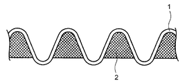
- FIG. 1 is a cross-sectional view of a sliding member according to Embodiment 1 of the present invention.
- the resin film 1 skin layer
- the back side becomes a concave part.
- the surface side on which the convex portion is formed forms the sliding surface of the sliding member.
- the back side is a recess, and the resin material 2 (load receiving portion) is filled in the recess.
- the resin film 1 that forms the sliding surface can be provided with physical properties (shape or surface frictional resistance) that have excellent wear resistance and low sliding resistance. It is also possible to provide an adhesive function necessary for fixing to a not-shown).
- the resin material 2 plays a role of receiving the load received from the sliding member, thereby preventing the embossed shape of the resin film 1 from being crushed. Therefore, even when a thermoplastic resin that is easily deformed is used as the material of the resin film 1, the embossed shape can be maintained, and the service life of the sliding member is long.
- the thermoplastic resin is very easy to process by heat, and it is not necessary to use a special manufacturing apparatus such as polishing or etching for embossing, so that both the manufacturing efficiency of the sliding member and the embossing strength can be achieved.
- the sliding member can be flexibly bent.
- the handling property is enhanced both in the manufacturing process and in the mounting process of the manufactured sliding member. Since the resin film 1 is responsible for the self-holding property of the sliding member, it needs to have a certain degree of elasticity. Therefore, it is preferable to make the elastic modulus of the resin material 2 lower than the elastic modulus of the resin film 1.
- FIG. 1 shows an example in which the resin film 1 is formed in a sine curve shape.
- the embossed shape is not limited to such a shape, and has a convex portion and a concave portion corresponding thereto, The area may be a flat part.
- the shape of the convex part and the concave part corresponding to this on the back surface of the resin film 1 can take a hemispherical shape, a spindle shape, a rectangular shape, and other various forms.
- the resin film 1 used in the present invention includes polyphenylene sulfide (PPS), amorphous polyarylate (PAR), polyetherimide (PEI), polyimide (PI), polysulfone (PSU), polyetheretherketone (PEEK), liquid crystal polyester So-called super engineering plastics such as (LCP), polybenzimidazole (PBI), and amorphous polyarylate (PAR) can be used, and in particular, the heat distortion temperature is 180 ° C. (based on JIS 7191, standard load: 0.25 GPa)
- the above is more suitable as a member used for an image forming apparatus (electrophotographic image forming apparatus) in a heat and pressure environment.
- thermoplastic resin or a thermosetting resin
- the thickness of the resin film 1 is preferably, for example, 20 ⁇ m or more, more preferably 30 ⁇ m or more, still more preferably 40 ⁇ m or more, and even more preferably, in order to increase the handling property by providing practical strength and appropriate stiffness. Is 50 ⁇ m or more. On the other hand, if it is too thick, the resin film 1 becomes too hard, lacking in flexibility, and the mounting efficiency to the fixing device decreases. Therefore, the thickness of the resin film 1 is preferably 200 ⁇ m or less, more preferably 150 ⁇ m or less, still more preferably 120 ⁇ m or less, and still more preferably 100 ⁇ m or less.
- the emboss shape is imparted to the resin film 1 by, for example, the following two methods.
- One is a method in which a fluid raw material is poured into a mold having an embossed shape, and an embossed shape is imparted simultaneously with the molding of the resin film 1.
- the other is to mechanically form a concavo-convex shape on a resin film that has been molded into a film in advance (which is flat before the concavo-convex is formed, and may be referred to as “resin film” hereinafter).
- resin film which is flat before the concavo-convex is formed, and may be referred to as “resin film” hereinafter).
- the embossed resin film 1 in the present invention may be obtained by any of the above methods as long as a convex part and a concave part are formed as a result.
- the embossed shape is preferably a shape in which concave portions and convex portions are alternately repeated, and the number of concave portions per area is preferably 200 pieces / square inch or more and 1000 pieces / square inch or less. This is because if it is less than 200 pieces / square inch, the contact area of the sliding surface increases and the sliding resistance increases. More preferably, it is 250 pieces / square inch or more, and further preferably, 300 pieces / square inch or more. On the other hand, the reason why the number is less than 1000 pieces / square inch is that when the number exceeds 1000 pieces / square inch, the emboss density becomes too high, and scraps generated from the resin film 1 itself during actual use are trapped by the sliding member. This is because the sliding resistance becomes unstable. More preferably 900 pieces / square inch or less, and still more preferably 800 pieces / square inch or less.
- a film is pressed against a flat plate, roll, belt or the like having a predetermined embossed shape on the surface under an appropriate temperature and pressure, and the surface shape is copied. From the viewpoint of productivity, processing with a roll or a belt is preferable.
- an embossed shape can be imparted to the surface of the resin film by simply performing a hot press treatment by sandwiching the resin film between the rubber-like elastic cushion and the metal wire mesh using a hot plate press.
- the pressing temperature is desirably set to a temperature lower than the melting point of the resin film, preferably 20 ° C. or higher (more preferably 30 ° C. or higher, more preferably 40 ° C. or higher) lower than the melting point. This is because if the heat press treatment is performed at a temperature near the melting point or higher, the possibility of damaging the resin film such as holes is increased.
- the resin material 2 to be introduced into the concave portion of the resin film 1 is, for example, a reactive liquid resin, a resin dissolved in a solvent, a resin dispersed in a liquid, a fine powder resin, a thermoplastic resin, or the like that exhibits fluidity by some means. If so, it can be preferably used.
- a reactive liquid resin and a resin dissolved in a solvent are in a liquid state at room temperature, and therefore, it is easy to fill the resin material 2 up to a fine embossed recess without using special equipment. Therefore, it is preferable.
- the resin material 2 may be a single resin or a mixture of several kinds of resins. Among these, resins exhibiting rubber elasticity such as silicone rubber and fluororubber are more preferable because they are flexible and have a function of dispersing stress.
- Resin material 2 can be blended with various fillers such as various pigments, conductive carbon, carbon nanofiber, silica, and metal powder. Moreover, it is also possible to mix
- a conductive filler is used as the filler material, the static electricity of the sliding member can be controlled. Further, when a color pigment is used, the sliding member can be given distinctiveness.
- the surface of the resin film 1 is subjected to wet surface treatment such as chromic acid treatment and various primer treatments.
- wet surface treatment such as chromic acid treatment and various primer treatments.
- dry surface treatment such as flame treatment, corona discharge treatment, or plasma treatment may be performed.
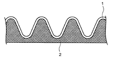
- the resin material 2 to be introduced into the recesses of the resin film 1 may be present in isolation (independently) for each recess, but each is continuous as shown in FIG. May be connected.
- the resin material 2 uses a resin that has a high elastic modulus and is difficult to bend, such as an epoxy resin
- it is preferable that the epoxy resin is present in isolation in the concave portion because the flexibility of the entire sheet is not impaired.
- the resin material 2 and the pressing member are in close contact, and there is no portion where the resin film 1 is directly fixed to the pressing member. The tensile stress applied to the film 1 is reduced, and the service life of the resin film 1 is extended.
- a thinner resin film 1 it is possible to use a thinner resin film 1.
- the use of a silicone resin (silicone rubber) for the resin material 2 is more effective.
- electrostatic charging can be suppressed because the resin material 2 is continuously connected.
- Saito Engineers for biaxially stretched film (trade name: Baiac, manufactured by Japan Gore-Tex Co., Ltd.) composed of a polyester-based liquid crystal polymer with a melting point of 340 ° C and a heat distortion temperature of 210 ° C
- an embossed shape (Square Ayame No. 1) made by Embosser, Inc.
- a hot press treatment was performed at a temperature of 200 ° C. to give the embossed shape, and a liquid crystal polymer film sample was obtained.
- the density of the recesses was 289 pieces / square inch, and the depth of the recesses was 200 ⁇ m.
- a liquid silicone resin (trade name: KE-106) and a curing catalyst (trade name: CAT-RG, both manufactured by Shin-Etsu Chemical Co., Ltd.) are measured as a resin material 2 at a weight ratio of 10/1. And mixed well.
- the sample of the liquid crystal polymer film subjected to the embossing process was spread on a glass plate without wrinkles and fixed with an adhesive tape.
- the liquid silicone resin was cast on the fixed liquid crystal polymer film, and the surface thereof was smoothed with a glass rod. Subsequently, it heat-processed for 15 minutes in a 150 degreeC thermostat, and liquid silicone resin was hardened completely, and it was set as the sliding member for a test.
- the amount of silicone resin applied after curing was 80 g / m 2 .
- the resin material 2 200 g of naphthalene type epoxy resin (trade name: HP-4032, manufactured by DIC Corporation), 10 g of powder dicyandiamide (trade name: DICY7, manufactured by Japan Epoxy Resin Corporation), 2-ethyl-4- 2 g of methylimidazole and 100 g of methyl ethyl ketone were placed in a stainless steel container and mixed and dispersed with a mixer for 30 minutes.
- naphthalene type epoxy resin trade name: HP-4032, manufactured by DIC Corporation
- 10 g of powder dicyandiamide trade name: DICY7, manufactured by Japan Epoxy Resin Corporation
- 2-ethyl-4- 2 g of methylimidazole 100 g of methyl ethyl ketone
- the biaxially stretched film of the polyester-based liquid crystal polymer imparted with the embossed shape used in Example 1 was spread over the glass plate and fixed with an adhesive tape, and then the adjusted naphthalene type epoxy resin was flown.
- the surface was smoothed with a glass rod.
- the epoxy resin was B-staged (semi-cured) by heat treatment in a constant temperature bath at 80 ° C. for 15 minutes.
- the film was removed from the glass plate, fixed to a stainless steel pin frame, and heat-treated in a constant temperature bath at 180 ° C. for 4 hours to further cure the epoxy resin to obtain a sliding member for testing.
- the application amount of the epoxy resin after curing was 50 g / m 2 .
- the sliding member obtained in Examples 1 and 2 is such that the resin material 2 is independently formed in each recess as shown in FIG.
- a polyimide varnish (trade name: Comporacene H700, manufactured by Arakawa Chemical Industries, Ltd.) is applied to a glass plate with an applicator to a thickness of 200 ⁇ m, then dried with a dryer at 100 ° C. for 15 minutes, and further heated. It heat-processed at 250 degreeC for 2 hours, and obtained the 40-micrometer-thick polyimide film.
- This film was combined with a 0.23 ⁇ ⁇ 30 mesh stainless steel mesh that had been mold-released with a silicone resin, and a polyimide film with a thickness of 75 ⁇ m was placed on the top and bottom, and a pressure of 5 kg / cm 2 was applied to the sample with a hot plate press at 300 ° C. A heat press treatment was performed for 10 minutes to copy the uneven pattern of the stainless mesh wire net.
- the resin material 2 was not applied to the film, and the resin material treatment was not performed, and a sliding sheet for testing was used as it was.
- Hot press test A sample and a 1 mm-thick silicone rubber sheet are sandwiched between two stainless steel mirror plates and subjected to a hot press treatment at a load of 5 kg / cm 2 and a temperature of 180 ° C. for 5 minutes to emboss the surface. The shape change was observed.
- Friction test Attach a polyimide film on the test stand side of the Gakushin friction tester (manufactured by Daiei Kagaku Seiki Seisakusho Co., Ltd.), attach a sample on the friction element side, place a load weight of 500 g, and put silicone oil on the polyimide film. Dripping and then rubbing 10,000 times to observe changes in the embossed shape of the surface.
Landscapes
- Physics & Mathematics (AREA)
- General Physics & Mathematics (AREA)
- Electrophotography Configuration And Component (AREA)
- Fixing For Electrophotography (AREA)
- Manufacture Of Macromolecular Shaped Articles (AREA)
- Compositions Of Macromolecular Compounds (AREA)
Abstract
本発明は、摺動性が高く、かつ、柔軟で折り曲げ加工のし易い摺動部材を提供することを目的とする。エンボス加工により表面側が凸部となり裏面側が凹部となるように形成され前記表面側が摺動面をなす樹脂膜1と、前記樹脂膜1の凹部に填装された樹脂材2とを有する摺動部材を作製する。この摺動部材を画像定着装置に用いる。
Description
本発明は、機械部品の摺動部分に用いられる摺動部材に関するものである。より詳細には、複写機、プリンター、ファクシミリ等の画像定着装置(電子写真画像形成装置)の摺動面に配置されるシート状の摺動部材(「摺動シート」と記載する場合もある)に関するものである。
地球環境保全、エネルギー資源の枯渇などの諸情勢により、近年、電気装置の省エネルギー化が求められている。例えば、プリンター、複写機、ファクシミリ等の画像形成装置の熱定着装置においても 高速化、立ち上げ時間の短縮、小型化、省エネルギーを目的として、エンドレスベルトを用いた熱定着方式が採用されている。
例えば複写装置では、ドラム状に形成された感光体を一様に帯電させ、この感光体を画像情報に基づいて制御された光で露光し、感光体上に静電潜像(トナー)を形成し、画像定着装置によって、このトナーを紙等の記録媒体上に未定着の状態で転写させ、加熱/加圧することにより記録媒体に定着させるものである。
例えば、特許文献1、2には、回転可能に配設される加圧ロールと、この加圧ロールに回転可能に圧接配置された筒状のエンドレスベルトとを備えた画像定着装置が記載されている。エンドレスベルトの内側には、加圧ロール側に向けてエンドレスベルトを押圧する加圧部材(押圧パッド)が設けられ、加圧部材とエンドレスベルトと間には、潤滑剤を含んだ摺動部材が設けられている。摺動部材は、エンドレスベルトが定着ロールの周速に遅れることなく従駆動させる役割を担っている。
摺動部材の摺動を一層円滑にする目的、及び、摺動部材の摩耗を減少させる目的で、通常は、摺動部材とエンドレスベルト間にはシリコーンオイル等の液状潤滑剤を介在させている。
この摺動部材には、特許文献2に記載されているようにガラス繊維を織ったガラスクロスに、四フッ化エチレン樹脂(ポリテトラフルオロエチレン)を含浸コーティングし、それを焼き付けたガラステフロン(登録商標)が重用されている。ガラステフロンは四フッ化エチレン樹脂自体が有する低摩擦性と、摺動対象物との接触面積の少なさ(摺動部材の織り布構造から生じる表面凸部に起因)による効果で、優れた摺動性を示す。
しかしながら、ガラステフロンは電子写真画像形成装置の熱定着装置の加熱加圧環境下で長時間使用されると、表面層の四フッ化エチレン樹脂層が収縮(クリープ)し、表面の凹凸が減少し、また、四フッ化エチレン樹脂層が摩耗してガラスクロスが露出する問題がある。ガラスクロスが露出するとエンドレスベルト1aが損傷し、定着画像の荒れの原因となる。また摺動抵抗が増大すると、熱定着装置に用いられている軸受け、ギア、モーターへの負担となり、エネルギーロスの増加や装置の故障を引き起こす原因となる。
このガラステフロンの問題を解決するために、ガラスクロスを使用しない種々の技術が開示されている。例えば、特許文献3には、摺動面に特殊な凹凸構造を採用したフッ素樹脂層からなる摺動シートが記載されている。しかし、この摺動シートを電子写真画像形成装置の熱定着装置の加熱加圧環境下で長時間使用すると、摺動面のフッ素樹脂のクリープと摩耗のため、特殊凹凸構造が潰れ、摺動面が平滑となって、摺動抵抗が増加する。
また、特許文献4および特許文献5のように、樹脂フィルムの表面にエンボス加工で凹凸を賦型した熱硬化性ポリイミドフィルムを摺動部材として使用する技術が記載されているが、薄い未硬化状態のポリイミド前駆体を取り扱う工程が煩雑であるため生産効率の向上には限界がある。
特許文献6には、ポリエーテルエーテルケトン(PEEK)を適用した画像形成装置の熱定着装置の摺動シートが記載されている。この摺動シートの表面はガラスクロスにより賦形され、多少の凹凸形状が形成されているが、その凹凸形状はかなり微細なものであり、画像形成装置の熱定着装置の作動環境下では凹凸形状が簡単に潰れてしまうため、摺動性は十分なものではない。
特許文献7には、単一の樹脂からなり、少なくともエンドレスベルトの摺動方向に関して、シート面内の位置に応じて単位面積当たりの樹脂量が実質的に異なることによって厚い部分と薄い部分を繰り返し有する摺動シートが記載されている。しかし、このような摺動シートを製造するためには、表面研磨やエッチングのための特殊な装置を要する。
上記従来の摺動部材(摺動シート)は、摺動性、又は摺動性の維持が十分ではなかった。上記特許文献7では、摺動性の向上の点では一定の効果を有するものの、製造工程が煩雑であり、しかも単一樹脂を用いて単位面積当たりの樹脂量が異なる厚い部分と薄い部分を構成しているため、使用する樹脂によっては摺動シートが硬くなる場合があり、また折り曲げ加工性に劣る。
本発明は上記のような状況に鑑みてなされたものであって、摺動性が高く、かつ、柔軟で折り曲げ加工のし易い摺動部材を提供することを目的とするものである。
上記目的を達し得た本発明の摺動部材は、エンボス加工により表面側が凸部となり裏面側が凹部となるように形成され前記表面側が摺動面をなす樹脂膜と、前記樹脂膜の凹部に填装された樹脂材とを有するものである。本発明では、摺動部材が樹脂膜(表皮層)と樹脂材(荷重受け層)とに分かれているため、これらに弾性率が異なる材料を適用することにより摺動部材の折り曲げに対する自由度が増し、摺動部材を柔軟に屈曲させることができるようになる。また、摺動部材の折り曲げ等の加工が容易となる。
上記摺動部材において、前記凸部の個数密度を200個/平方インチ以上とすることが好ましい。摺動性をより確実に向上させるためである。
上記摺動部材において、前記樹脂材の弾性率を前記樹脂膜の弾性率よりも低くすることが好ましい。
上記摺動部材において、前記凹部が前記樹脂材で満たされており、かつ、隣り合う凹部の樹脂材同士が連続的に繋がっている態様をとることができる。
上記摺動部材において、前記樹脂膜が熱可塑性樹脂膜で構成することが好ましい。熱可塑性樹脂を用いると樹脂膜へのエンボス形状の付与が容易となるからである。
上記摺動部材において、前記熱熱可塑性樹脂膜が液晶樹脂膜、ポリイミド樹脂膜、ポリエーテルエーテルケトン膜で構成することが好ましい。これらの樹脂は、耐熱性に優れているためである。
上記摺動部材において、前記樹脂材は、常温で液状の樹脂を、硬化させたものを用いることができる。
上記摺動部材において、前記樹脂材として、シリコーン樹脂、フッ素ゴム等を用いることができる。ゴム弾性の特性により、摺動部材の柔軟性を高めることが可能となるためである。
上記摺動部材において、前記樹脂膜の厚さを20μm以上、200μm以下とすることが好ましい。摺動部材のハンドリング性を維持しつつも柔軟性を持たせるためである。
上記摺動部材において、前記樹脂膜の表面であって前記樹脂材に対向する側は、クロム酸処理、プライマー処理、火炎処理、コロナ放電処理、又はプラズマ処理が施されていることが好ましい。樹脂膜と樹脂材との接着性を高めるためである。
本発明の摺動部材は、樹脂膜にエンボス加工が施されていることにより摺動性が高く、また、エンボス加工による凹部に樹脂膜とは異なる樹脂材が填装されているために、一定の強度は保ちながらも柔軟性が高い摺動部材を提供することができるものであり、長寿命で画像品質の高い画像定着装置を製造することが可能となる。
以下、本発明の実施の形態にかかる摺動部材について説明する。本発明の摺動部材は、上記したようにエンボス加工により表面側が凸部となり裏面側が凹部となるように形成された樹脂膜と、樹脂膜の凹部に填装された樹脂材とを有するものである。以下、図面を参照しながら、本発明の基本的構成要素である樹脂膜と樹脂材について詳細に説明する。
(実施の形態1)
図1は、本発明の実施の形態1における摺動部材の断面図である。図1において、樹脂膜1(表皮層)は、表面側が凸部となり裏面側が凹部となるようにエンボス加工されている。凸部が形成された表面側が摺動部材の摺動面をなす。一方、その裏側は凹部であり、凹部には樹脂材2(荷重受け部)が填装されている。本発明では、摺動部材を樹脂膜1と樹脂材2とに分けているため、摺動部材の強度、摺動性等、必要な特性を付与しやすくなる。例えば、摺動面をなす樹脂膜1には耐摩耗性に優れ、滑り抵抗の小さな物性(形状、或いは表面摩擦抵抗)を付与することができ、樹脂材2には、定着ロールの押圧部材(図示せず)への固定に必要な粘着機能を付与することも可能である。
図1は、本発明の実施の形態1における摺動部材の断面図である。図1において、樹脂膜1(表皮層)は、表面側が凸部となり裏面側が凹部となるようにエンボス加工されている。凸部が形成された表面側が摺動部材の摺動面をなす。一方、その裏側は凹部であり、凹部には樹脂材2(荷重受け部)が填装されている。本発明では、摺動部材を樹脂膜1と樹脂材2とに分けているため、摺動部材の強度、摺動性等、必要な特性を付与しやすくなる。例えば、摺動面をなす樹脂膜1には耐摩耗性に優れ、滑り抵抗の小さな物性(形状、或いは表面摩擦抵抗)を付与することができ、樹脂材2には、定着ロールの押圧部材(図示せず)への固定に必要な粘着機能を付与することも可能である。
また樹脂材2は摺動部材から受ける荷重を受け止める役割を果たすことにより、樹脂膜1のエンボス形状が押し潰されることを防止する。したがって、樹脂膜1の材料として変形しやすい熱可塑性樹脂を用いた場合であっても、エンボス形状を維持することができ、摺動部材の使用寿命は長い。熱可塑性樹脂は熱による加工が大変容易であり、エンボス加工に研磨やエッチング等の特別な製造装置を用いる必要がないため、摺動部材の製造効率とエンボス強度を両立することができる。
また、樹脂膜1と樹脂材2で弾性率が異なる材料を選択することにより摺動部材の折り曲げに対する応力が軽減されるため、摺動部材が柔軟に屈曲できるようになり、摺動部材自体の製造工程においても、製造された摺動部材の取付け工程においても、そのハンドリング性が高まる。樹脂膜1は、摺動部材の自己保持性を担うものであるので、ある程度の弾性率があることを要する。したがって、樹脂材2の弾性率を樹脂膜1の弾性率よりも低くすることが好ましい。
図1では、樹脂膜1がサインカーブ形状により形成された例を示したが、エンボス形状はこのような形状に限定されるものではなく、凸部およびこれに対応する凹部を有し、その他のエリアは平坦部である形状でもよい。また、凸部および樹脂膜1の裏面でこれに対応する凹部の形状は、半球状、錘状、矩形状、その他、様々な形態をとることができる。
次に、樹脂膜1に用いられる材料の一例を挙げる。本発明に使用する樹脂膜1はポリフェニレンスルフィド(PPS)、非晶ポリアリレート(PAR)、ポリエーテルイミド(PEI)、ポリイミド(PI)、ポリサルホン(PSU)、ポリエーテルエーテルケトン(PEEK)、液晶ポリエステル(LCP)、ポリベンゾイミダゾール(PBI)、非晶ポリアリレート(PAR)等の所謂スーパーエンプラを使用することができ、特に熱変形温度が180℃(JIS 7191に準拠、基準荷重:0.25GPa)以上のものは、加熱加圧環境下で画像形成装置(電子写真画像形成装置)に用いる部材として一層好適である。
熱変形温度が180℃未満であると、熱転写定着装置の使用環境および機械的ストレスに耐えられずエンボス形状が消失するため、摺動抵抗が経時的に増加して動作に不具合を生じる。したがって、本発明にかかる樹脂膜1には熱可塑性樹脂、熱硬化性樹脂のいずれも用いることができるが、エンボス加工の容易性の観点からは熱可塑性樹脂を用いることがより好適である。
樹脂膜1の厚さは、実用的な強度、および適度なコシを持たせてハンドリング性を高めるため、例えば20μm以上とすることが好ましく、より好ましくは30μm以上、さらに好ましくは40μm以上、一層好ましくは50μm以上とする。一方、厚くなりすぎると樹脂膜1が硬くなりすぎ、柔軟性に欠け、定着装置への装着効率が低下する。そのため、樹脂膜1の厚さは例えば200μm以下とすることが好ましく、より好ましくは150μm以下、さらに好ましくは120μm以下、一層好ましくは100μm以下とする。
樹脂膜1へのエンボス形状の付与は、例えば次の2つの方法により行う。一つは、流動性のある原料をエンボス形状付きの金型に流し込み、樹脂膜1の成型と同時にエンボス形状の付与を行う方法である。もう一つは、予めフィルム状に成型された樹脂膜(凹凸が形成される前の平坦なものであり、以下、「樹脂フィルム」と記載する場合がある)に機械的に凹凸形状を施すものであり、経済的な観点でのメリットがある。本発明におけるエンボス加工された樹脂膜1とは、結果的に凸部および凹部が形成されたものであれば、上記何れの方法により得たものでもよい。
エンボス形状は、凹部および凸部が交互に繰り返される形状が好ましく、凹部分の面積当たりの個数は200個/平方インチ以上、1000個/平方インチ以下が好ましい。200個/平方インチ未満であると摺動面の接触面積が増え、摺動抵抗が増加するからである。より好ましくは250個/平方インチ以上、さらに好ましくは300個/平方インチ以上とする。一方、1000個/平方インチ以下としたのは、1000個/平方インチを超えるとエンボス密度が大きくなりすぎて、実使用時に樹脂膜1自体から発生する削りカスなどが摺動部材にトラップされて、摺動抵抗が不安定になるからである。より好ましくは900個/平方インチ以下、さらに好ましくは800個/平方インチ以下とする。
エンボス加工は、表面に所定のエンボス形状を形成した平板、ロール、ベルト等に適切な温度および圧力下にフィルムを押し付けその表面形状を写し取るものである。生産性の観点からロールあるいはベルトによる加工が好適である。また簡易的には熱平板プレス機を用いて、ゴム状弾性クッションと金属ワイヤーメッシュの間に樹脂フィルムを挟んで熱プレス処理することにより、樹脂フィルムの表面にエンボス形状を付与することができる。プレス温度は、樹脂フィルムの融点以下、好ましくは融点より20℃以上(より好ましくは30℃以上、さらに好ましくは40℃以上)低い温度とすることが望ましい。融点近辺、或いはそれ以上の温度で熱プレス処理を行うと、穴空きなど、樹脂フィルムにダメージを与える可能性が高くなるためである。
樹脂膜1の凹部に導入する樹脂材2は、例えば、反応性液状樹脂、溶剤に溶かした樹脂、液体に分散させた樹脂、微粉末樹脂、熱可塑性樹脂など、何らかの手段で流動性を示す樹脂であれば好ましく使用できる。これらの樹脂のうち、反応性液状樹脂、溶剤に溶かした樹脂は、常温で液状であるため、特殊な設備を用いずとも、細かいエンボス形状の凹部まで樹脂材2を充填することが容易であるので好適である。凹部への導入後に、樹脂材2を硬化させると耐熱性が出現する。樹脂材2は単一の樹脂であっても、或いは、数種類の樹脂を混合したものであっても良い。中でも、シリコーンゴム、フッ素ゴムなどゴム弾性を示す樹脂は柔軟でストレスを分散する機能も有しているのでさらに好適である。
樹脂材2には、各種顔料、導電性カーボン、カーボンナノファイバー、シリカ、金属粉など各種のフィラー類を配合する事ができる。また、発泡剤を配合して発泡体とすることも可能である。樹脂材2にフィラー等を配合するのは、注型された樹脂の物性(強度、伸度、柔軟性など)を調整し、或いは改善するためである。フィラー材料として導電性フィラーを用いた場合は、摺動部材の静電気をコントロールすることができる。また、カラー顔料を用いた場合は、摺動部材に識別性を付与することができる。
樹脂膜1と樹脂材2の接着性を向上させるため、樹脂膜1の凹部に樹脂材2を導入するのに先立って、樹脂膜1の表面にクロム酸処理、各種プライマー処理などの湿式表面処理、或は火炎処理、コロナ放電処理、プラズマ処理など乾式の表面処理を施しても良い。
(実施の形態2)
樹脂膜1の凹部に導入する樹脂材2は、図1に示したように、1つの凹部ごとに孤立(独立)して存在していてもよいが、図2に示すように、各々が連続的に繋がっていてもよい。樹脂材2として、エポキシ樹脂など弾性率が高く、曲げ難い樹脂を使用する場合は、エポキシ樹脂が凹部に孤立して存在する方がシート全体の柔軟性を損なわないので好ましい。一方、樹脂材2が連続的に繋がっている場合は、樹脂材2と押圧部材とが密着し、樹脂膜1が押圧部材に直接固定される部分が存在しないため、摺動部材の使用時に樹脂膜1にかかる引張応力が減少し、樹脂膜1の使用寿命が伸びる。或いは、より薄い樹脂膜1を使用することも可能になる。特に、樹脂材2にシリコーン樹脂(シリコーンゴム)を使用すれば一層効果的である。また、樹脂材2に導電フィラーを用いた場合、樹脂材2が連続的に繋がっていることにより静電気の帯電を抑制できる。
樹脂膜1の凹部に導入する樹脂材2は、図1に示したように、1つの凹部ごとに孤立(独立)して存在していてもよいが、図2に示すように、各々が連続的に繋がっていてもよい。樹脂材2として、エポキシ樹脂など弾性率が高く、曲げ難い樹脂を使用する場合は、エポキシ樹脂が凹部に孤立して存在する方がシート全体の柔軟性を損なわないので好ましい。一方、樹脂材2が連続的に繋がっている場合は、樹脂材2と押圧部材とが密着し、樹脂膜1が押圧部材に直接固定される部分が存在しないため、摺動部材の使用時に樹脂膜1にかかる引張応力が減少し、樹脂膜1の使用寿命が伸びる。或いは、より薄い樹脂膜1を使用することも可能になる。特に、樹脂材2にシリコーン樹脂(シリコーンゴム)を使用すれば一層効果的である。また、樹脂材2に導電フィラーを用いた場合、樹脂材2が連続的に繋がっていることにより静電気の帯電を抑制できる。
以下、実施例を挙げて本発明をより具体的に説明するが、本発明はもとより下記実施例によって制限を受けるものではなく、前・後記の趣旨に適合し得る範囲で適当に変更を加えて実施することも勿論可能であり、それらはいずれも本発明の技術的範囲に包含される。
融点が340℃、熱変形温度が210℃のポリエステル系液晶ポリマーで構成され、厚さが50μmの2軸延伸フィルム(商品名:バイアック、ジャパンゴアテックス株式会社製)に対して、サイトウエンヂニアーズ株式会社製エンボッサーのエンボス形状(四角あやめ1号)を用い、温度200℃で熱プレス処理してエンボス形状を付与し、液晶ポリマーフィルムのサンプルを得た。凹部の密度は289個/平方インチ、凹部の深さは200μmであった。
次いで、樹脂材2として液状シリコーン樹脂(商品名:KE-106)、及び硬化触媒(商品名:CAT-RG、いずれも、信越化学工業株式会社製)を重量比で10/1の割合で計り取り、十分に混合した。
次に、ガラス板上に、エンボス加工を施した上記の液晶ポリマーフィルムのサンプルを皺(シワ)無く広げて接着テープで固定した。固定した液晶ポリマーフィルム上に上記液状シリコーン樹脂を流延し、その表面をガラス棒で平滑に均した。次いで、150℃の恒温槽で15分間熱処理して液状シリコーン樹脂を完全に硬化させ試験用の摺動部材とした。硬化後のシリコーン樹脂の塗布量は80g/m2であった。
冷却後、ガラス板から摺動部材を取り外し、シリコーン樹脂非コーティング面を摺動面、コーティング面を固定面として後述する評価試験を行った。
樹脂材2として、ナフタレン型エポキシ樹脂(商品名:HP-4032、DIC株式会社製)を200gと、粉末ジシアンジアミド(商品名:DICY7、ジャパンエポキシレジン株式会社製)を10g、2-エチル-4-メチルイミダゾールを2g、及び、メチルエチルケトン100gをステンレス製容器に入れてミキサーで30分間混合分散させた。
次に、実施例1で用いたエンボス形状を付与したポリエステル系液晶ポリマーの2軸延伸フィルムをガラス板上に皺無く広げて接着テープで固定した後、調整した上記のナフタレン型のエポキシ樹脂を流延し、その表面をガラス棒で平滑に均した。80℃の恒温槽で15分間熱処理して上記エポキシ樹脂をBステージ化(半硬化)した。次に、ガラス板から上記フィルムを取り外して、ステンレス製のピンフレームに皺無く固定して180℃の恒温槽で4時間熱処理してエポキシ樹脂を更に硬化させ、試験用の摺動部材とした。硬化後のエポキシ樹脂の塗布量は50g/m2であった。なお、実施例1および2で得られた摺動部材は、図1のように樹脂材2が各々の凹部に独立して形成されたものである。
(比較例1)
実施例1で調製したポリエステル系液晶ポリマーの2軸延伸フィルムに対して樹脂材2を塗布せず、そのまま試験用の摺動部材とした。
実施例1で調製したポリエステル系液晶ポリマーの2軸延伸フィルムに対して樹脂材2を塗布せず、そのまま試験用の摺動部材とした。
(比較例2)
ポリイミドワニス(商品名:コンポラセンH700、荒川化学工業株式会社製)をガラス板上にアプリケーターで200μmの厚さに塗布し、次いで100℃の乾燥器で15分間乾燥処理し、更に、昇温して250℃で2時間熱処理して40μm厚さのポリイミドフィルムを得た。このフィルムをシリコーン樹脂で離型処理した0.23φ×30メッシュのステンレスメッシュと合わせて上下に75μm厚さのポリイミドフィルムを配して300℃の熱板プレスで5kg/cm2の圧力を試料にかけ、10分間熱プレス処理をしてステンレスメッシュ金網の凹凸模様を写し取った。このフィルムに対して樹脂材2を塗布せず、樹脂材処理をせずそのまま試験用の摺動シートとした。
ポリイミドワニス(商品名:コンポラセンH700、荒川化学工業株式会社製)をガラス板上にアプリケーターで200μmの厚さに塗布し、次いで100℃の乾燥器で15分間乾燥処理し、更に、昇温して250℃で2時間熱処理して40μm厚さのポリイミドフィルムを得た。このフィルムをシリコーン樹脂で離型処理した0.23φ×30メッシュのステンレスメッシュと合わせて上下に75μm厚さのポリイミドフィルムを配して300℃の熱板プレスで5kg/cm2の圧力を試料にかけ、10分間熱プレス処理をしてステンレスメッシュ金網の凹凸模様を写し取った。このフィルムに対して樹脂材2を塗布せず、樹脂材処理をせずそのまま試験用の摺動シートとした。
実施例1および2、比較例1および2で得られた摺動部材には、次の3つの試験を行った。
1.熱プレス試験
2枚のステンレス製鏡面板の間に 試料と厚さ1mmのシリコーンゴムシートを合わせて挟みこみ、試料への荷重5kg/cm2、温度180℃で5分間熱プレス処理を行い、表面のエンボス形状の変化を観察した。
2枚のステンレス製鏡面板の間に 試料と厚さ1mmのシリコーンゴムシートを合わせて挟みこみ、試料への荷重5kg/cm2、温度180℃で5分間熱プレス処理を行い、表面のエンボス形状の変化を観察した。
2.摩擦試験
学振型摩擦試験機(株式会社大栄科学精器製作所製)の試験台側にポリイミドフィルムを、摩擦子側に試料を取り付け、荷重分銅500gを載せて、ポリイミドフィルム上にシリコーンオイルを1滴垂らし、その後10000回摩擦して表面のエンボス形状の変化を観察した。
学振型摩擦試験機(株式会社大栄科学精器製作所製)の試験台側にポリイミドフィルムを、摩擦子側に試料を取り付け、荷重分銅500gを載せて、ポリイミドフィルム上にシリコーンオイルを1滴垂らし、その後10000回摩擦して表面のエンボス形状の変化を観察した。
3.実機試験
カラープリンター(商品名:DocuPrint C1100、富士ゼロックス株式会社製)の画像定着装置及び紙の反転装置のユニット部分にあるフリーベルトロールセットを取り出し、付属の摺動部材と同一形状にカットしたサンプルを替わりに取り付け、プリンターに組み込んだ。この実機によりA4サイズの紙を10万枚処理した後、摺動部材とベルトの内面を観察した。これらの結果を表1に示す。
カラープリンター(商品名:DocuPrint C1100、富士ゼロックス株式会社製)の画像定着装置及び紙の反転装置のユニット部分にあるフリーベルトロールセットを取り出し、付属の摺動部材と同一形状にカットしたサンプルを替わりに取り付け、プリンターに組み込んだ。この実機によりA4サイズの紙を10万枚処理した後、摺動部材とベルトの内面を観察した。これらの結果を表1に示す。

表1から、分かるように、樹脂膜1の凹部に樹脂材を填装していない比較例1および比較例2では、各種の試験の実行により、エンボス形状が小さくなり、或いは消失し、実機試験においても異音が発生するなど不具合が発生した。これに対して、樹脂膜1の凹部に樹脂材を填装した実施例1および実施例2では、熱プレス試験、摩擦試験、実機試験を行った後でも樹脂膜1のエンボス形状は十分維持されており、摺動性が高いままで継続使用が可能であることがわかる。
1 樹脂膜
2 樹脂材
2 樹脂材
Claims (13)
- エンボス加工により表面側が凸部となり裏面側が凹部となるように形成され前記表面側が摺動面をなす樹脂膜と、前記樹脂膜の凹部に填装された樹脂材とを有する摺動部材。
- 前記凸部の個数密度が200個/平方インチ以上である請求項1に記載の摺動部材。
- 前記樹脂材の弾性率が前記樹脂膜の弾性率よりも低い請求項1または2に記載の摺動部材。
- 前記凹部が前記樹脂材で満たされており、かつ、隣り合う凹部の樹脂材同士が連続的に繋がっている請求項1~3のいずれかに記載の摺動部材。
- 前記樹脂膜が熱可塑性樹脂膜である請求項1~4のいずれかに記載の摺動部材。
- 前記熱可塑性樹脂膜が液晶樹脂膜である請求項5に記載の摺動部材。
- 前記熱可塑性樹脂膜がポリイミド樹脂膜である請求項5に記載の摺動部材。
- 前記熱可塑性樹脂膜がポリエーテルエーテルケトン膜である請求項5に記載の摺動部材。
- 前記樹脂材は、常温で液状の樹脂を、硬化させたものである請求項5~8のいずれかに記載の摺動部材。
- 前記樹脂材がシリコーン樹脂である請求項1~9のいずれかに記載の摺動部材。
- 前記樹脂材がフッ素ゴムである請求項1~9のいずれかに記載の摺動部材。
- 前記樹脂膜の厚さが20μm以上、200μm以下である請求項1~11のいずれかに記載の摺動部材。
- 前記樹脂膜の表面であって前記樹脂材に対向する側は、クロム酸処理、プライマー処理、火炎処理、コロナ放電処理、又はプラズマ処理が施されている請求項1~12のいずれかに記載の摺動部材。
Applications Claiming Priority (2)
| Application Number | Priority Date | Filing Date | Title |
|---|---|---|---|
| JP2009-125662 | 2009-05-25 | ||
| JP2009125662A JP2010271656A (ja) | 2009-05-25 | 2009-05-25 | 摺動部材 |
Publications (1)
| Publication Number | Publication Date |
|---|---|
| WO2010137559A1 true WO2010137559A1 (ja) | 2010-12-02 |
Family
ID=43222667
Family Applications (1)
| Application Number | Title | Priority Date | Filing Date |
|---|---|---|---|
| PCT/JP2010/058751 Ceased WO2010137559A1 (ja) | 2009-05-25 | 2010-05-24 | 摺動部材 |
Country Status (2)
| Country | Link |
|---|---|
| JP (1) | JP2010271656A (ja) |
| WO (1) | WO2010137559A1 (ja) |
Families Citing this family (5)
| Publication number | Priority date | Publication date | Assignee | Title |
|---|---|---|---|---|
| JP2013167730A (ja) | 2012-02-15 | 2013-08-29 | Brother Ind Ltd | 定着用ローラおよびその製造方法 |
| JP2013218175A (ja) * | 2012-04-10 | 2013-10-24 | Nok Corp | 定着用加圧部材及びその製造方法 |
| WO2017047724A1 (ja) * | 2015-09-17 | 2017-03-23 | Ntn株式会社 | 定着装置用摺動部材の製造方法 |
| JP6817680B2 (ja) * | 2015-09-17 | 2021-01-20 | Ntn株式会社 | 定着装置用摺動部材の製造方法 |
| JP6759614B2 (ja) * | 2016-02-12 | 2020-09-23 | 株式会社リコー | 定着装置および画像形成装置 |
Citations (6)
| Publication number | Priority date | Publication date | Assignee | Title |
|---|---|---|---|---|
| JP2003107936A (ja) * | 2001-09-27 | 2003-04-11 | Fuji Xerox Co Ltd | 定着装置 |
| JP2004198655A (ja) * | 2002-12-17 | 2004-07-15 | Fuji Xerox Co Ltd | 定着装置、およびそれを用いた電子写真装置 |
| JP2005157303A (ja) * | 2003-11-07 | 2005-06-16 | Ricoh Co Ltd | 定着用部材、定着用ローラ、定着装置及び画像形成装置 |
| JP2006047769A (ja) * | 2004-08-05 | 2006-02-16 | Fuji Xerox Co Ltd | 定着装置 |
| JP2006119263A (ja) * | 2004-10-20 | 2006-05-11 | Canon Inc | 定着装置 |
| JP2009015227A (ja) * | 2007-07-09 | 2009-01-22 | Konica Minolta Business Technologies Inc | 定着器用の摺動シートおよびその製造方法、定着器並びに画像形成装置 |
-
2009
- 2009-05-25 JP JP2009125662A patent/JP2010271656A/ja not_active Withdrawn
-
2010
- 2010-05-24 WO PCT/JP2010/058751 patent/WO2010137559A1/ja not_active Ceased
Patent Citations (6)
| Publication number | Priority date | Publication date | Assignee | Title |
|---|---|---|---|---|
| JP2003107936A (ja) * | 2001-09-27 | 2003-04-11 | Fuji Xerox Co Ltd | 定着装置 |
| JP2004198655A (ja) * | 2002-12-17 | 2004-07-15 | Fuji Xerox Co Ltd | 定着装置、およびそれを用いた電子写真装置 |
| JP2005157303A (ja) * | 2003-11-07 | 2005-06-16 | Ricoh Co Ltd | 定着用部材、定着用ローラ、定着装置及び画像形成装置 |
| JP2006047769A (ja) * | 2004-08-05 | 2006-02-16 | Fuji Xerox Co Ltd | 定着装置 |
| JP2006119263A (ja) * | 2004-10-20 | 2006-05-11 | Canon Inc | 定着装置 |
| JP2009015227A (ja) * | 2007-07-09 | 2009-01-22 | Konica Minolta Business Technologies Inc | 定着器用の摺動シートおよびその製造方法、定着器並びに画像形成装置 |
Also Published As
| Publication number | Publication date |
|---|---|
| JP2010271656A (ja) | 2010-12-02 |
Similar Documents
| Publication | Publication Date | Title |
|---|---|---|
| US5099560A (en) | Elastic fixing roller | |
| JP4774769B2 (ja) | シート部材、および画像形成装置 | |
| JP2989953B2 (ja) | 定着装置及び定着用エンドレスベルト | |
| CN106062642B (zh) | 定影构件、定影装置及图像形成设备 | |
| US20110091252A1 (en) | Pressing member and image heating member using the pressing member | |
| CN101978325B (zh) | 定影元件、定影元件的制造方法、定影元件的转动体、定影装置和图像形成装置 | |
| US6865362B2 (en) | Heater having metallic substrate and image heating apparatus using heater | |
| JP6357875B2 (ja) | 定着部材、定着装置及び画像形成装置 | |
| JP2010211220A (ja) | 定着装置 | |
| WO2010137559A1 (ja) | 摺動部材 | |
| JP6269030B2 (ja) | 定着部材、定着装置、及び画像形成装置 | |
| US9260606B2 (en) | Silicone rubber sponge and rubber-covered roller | |
| JP3658305B2 (ja) | 加熱装置及び画像形成装置 | |
| JP2005049455A (ja) | ロール成型体及びそれを用いたローラ | |
| JP6881988B2 (ja) | 電子写真用部材の製造方法 | |
| JP5492397B2 (ja) | 弾性ローラ及び定着装置 | |
| JP5067929B2 (ja) | 定着ローラの製造方法 | |
| JP6390304B2 (ja) | 樹脂管状体、定着装置、および画像形成装置 | |
| JPH0869862A (ja) | 面状ヒータ及びトナー定着装置 | |
| JP3208913B2 (ja) | 定着装置及び定着ローラー | |
| JP2011527772A (ja) | デジタル画像装置にて使用するエンドレスベルト | |
| JP2004115564A (ja) | 表面離型性材料および表面離型性部材 | |
| JP5119724B2 (ja) | 定着装置用摺動部材、定着装置及び画像形成装置 | |
| JP5137170B2 (ja) | 半導電性ローラの製造方法 | |
| JP4244754B2 (ja) | 管状物および定着装置 |
Legal Events
| Date | Code | Title | Description |
|---|---|---|---|
| 121 | Ep: the epo has been informed by wipo that ep was designated in this application |
Ref document number: 10780514 Country of ref document: EP Kind code of ref document: A1 |
|
| NENP | Non-entry into the national phase |
Ref country code: DE |
|
| 122 | Ep: pct application non-entry in european phase |
Ref document number: 10780514 Country of ref document: EP Kind code of ref document: A1 |