WO2010131624A1 - レール圧制御方法及びコモンレール式燃料噴射制御装置 - Google Patents
レール圧制御方法及びコモンレール式燃料噴射制御装置 Download PDFInfo
- Publication number
- WO2010131624A1 WO2010131624A1 PCT/JP2010/057880 JP2010057880W WO2010131624A1 WO 2010131624 A1 WO2010131624 A1 WO 2010131624A1 JP 2010057880 W JP2010057880 W JP 2010057880W WO 2010131624 A1 WO2010131624 A1 WO 2010131624A1
- Authority
- WO
- WIPO (PCT)
- Prior art keywords
- discharge
- discharge amount
- pressure
- pressure pump
- amount
- Prior art date
- Legal status (The legal status is an assumption and is not a legal conclusion. Google has not performed a legal analysis and makes no representation as to the accuracy of the status listed.)
- Ceased
Links
Images




Classifications
-
- F—MECHANICAL ENGINEERING; LIGHTING; HEATING; WEAPONS; BLASTING
- F02—COMBUSTION ENGINES; HOT-GAS OR COMBUSTION-PRODUCT ENGINE PLANTS
- F02D—CONTROLLING COMBUSTION ENGINES
- F02D41/00—Electrical control of supply of combustible mixture or its constituents
- F02D41/30—Controlling fuel injection
- F02D41/38—Controlling fuel injection of the high pressure type
- F02D41/3809—Common rail control systems
- F02D41/3836—Controlling the fuel pressure
- F02D41/3845—Controlling the fuel pressure by controlling the flow into the common rail, e.g. the amount of fuel pumped
-
- F—MECHANICAL ENGINEERING; LIGHTING; HEATING; WEAPONS; BLASTING
- F02—COMBUSTION ENGINES; HOT-GAS OR COMBUSTION-PRODUCT ENGINE PLANTS
- F02D—CONTROLLING COMBUSTION ENGINES
- F02D41/00—Electrical control of supply of combustible mixture or its constituents
- F02D41/02—Circuit arrangements for generating control signals
- F02D41/14—Introducing closed-loop corrections
- F02D41/1401—Introducing closed-loop corrections characterised by the control or regulation method
-
- F—MECHANICAL ENGINEERING; LIGHTING; HEATING; WEAPONS; BLASTING
- F02—COMBUSTION ENGINES; HOT-GAS OR COMBUSTION-PRODUCT ENGINE PLANTS
- F02D—CONTROLLING COMBUSTION ENGINES
- F02D41/00—Electrical control of supply of combustible mixture or its constituents
- F02D41/02—Circuit arrangements for generating control signals
- F02D41/14—Introducing closed-loop corrections
- F02D41/1401—Introducing closed-loop corrections characterised by the control or regulation method
- F02D2041/1409—Introducing closed-loop corrections characterised by the control or regulation method using at least a proportional, integral or derivative controller
-
- F—MECHANICAL ENGINEERING; LIGHTING; HEATING; WEAPONS; BLASTING
- F02—COMBUSTION ENGINES; HOT-GAS OR COMBUSTION-PRODUCT ENGINE PLANTS
- F02D—CONTROLLING COMBUSTION ENGINES
- F02D41/00—Electrical control of supply of combustible mixture or its constituents
- F02D41/02—Circuit arrangements for generating control signals
- F02D41/14—Introducing closed-loop corrections
- F02D41/1401—Introducing closed-loop corrections characterised by the control or regulation method
- F02D2041/1413—Controller structures or design
- F02D2041/1422—Variable gain or coefficients
-
- F—MECHANICAL ENGINEERING; LIGHTING; HEATING; WEAPONS; BLASTING
- F02—COMBUSTION ENGINES; HOT-GAS OR COMBUSTION-PRODUCT ENGINE PLANTS
- F02M—SUPPLYING COMBUSTION ENGINES IN GENERAL WITH COMBUSTIBLE MIXTURES OR CONSTITUENTS THEREOF
- F02M59/00—Pumps specially adapted for fuel-injection and not provided for in groups F02M39/00 -F02M57/00, e.g. rotary cylinder-block type of pumps
- F02M59/20—Varying fuel delivery in quantity or timing
- F02M59/36—Varying fuel delivery in quantity or timing by variably-timed valves controlling fuel passages to pumping elements or overflow passages
- F02M59/366—Valves being actuated electrically
Definitions
- the present invention relates to rail pressure control in a common rail fuel injection control device, and more particularly, to the improvement of stability and reliability of rail pressure control.
- a common rail fuel injection control device for a vehicle internal combustion engine is configured to inject high-pressure fuel accumulated in a common rail into a cylinder of the internal combustion engine by a fuel injection valve at a predetermined injection timing.
- a common rail fuel injection control device the control of the common rail pressure (rail pressure) is directly related to the quality of the fuel injection characteristics, so it is important how stable and reliable control is performed.
- Various control methods have been proposed from various viewpoints.
- the flow rate of fuel fed into the plunger chamber of the high-pressure pump provided upstream of the common rail can be controlled by an electromagnetic proportional valve, and the fuel to the plunger chamber of the high-pressure pump is adjusted so that the fuel pressure required by the engine is achieved.
- Various methods have been proposed in which a desired rail pressure can be obtained by adjusting the flow rate of the gas by using an electromagnetic proportional valve (see, for example, Patent Document 1).
- the electromagnetic proportional valve A typical characteristic of the change in the fuel discharge amount of the high-pressure pump with respect to the energizing current is mapped and stored as a standard characteristic, and based on this, an electromagnetic proportional valve is used to achieve the rail pressure required from the running state A method for controlling the energization of the battery is employed. Further, in this case, the energization control of the electromagnetic proportional valve is performed by so-called PID control, and the learning control is applied to the PID control, so that the mapped standard characteristics and the actual electromagnetic proportional valve are used. A method of making it possible to cope with variations in the variation characteristics of the discharge amount of the high-pressure pump with respect to the current flow is also often used.
- the present invention has been made in view of the above circumstances, and a rail pressure control method and a common rail type that enable appropriate rail pressure control even when the discharge characteristics of the high pressure pump change depending on the rotation speed of the high pressure pump.
- a fuel injection control device is provided.
- the solenoid valve for adjusting the inflow amount provided to the high-pressure pump that pumps the high-pressure fuel to the common rail is adjustable, and the rail pressure of the common rail is set to the target rail pressure. Therefore, the drive pressure is controlled by PID feedback control according to the deviation between the actual rail pressure of the common rail and the target rail pressure, thereby controlling the discharge amount of the high pressure pump to control the rail pressure of the common rail to the target rail pressure.
- a rail pressure control method in a common rail fuel injection control device configured to be possible, There is provided a rail pressure control method configured to switch a PID constant in the PID control in accordance with the discharge amount of the high pressure pump so as to cope with a change in discharge characteristics of the high pressure pump.
- an electromagnetic valve for adjusting an inflow amount provided so as to be able to adjust an inflow amount of fuel to a high-pressure pump that pumps high-pressure fuel to the common rail is controlled by the control unit by the rail pressure of the common rail. Is controlled by PID feedback control according to the deviation between the actual rail pressure of the common rail and the target rail pressure, and the discharge amount of the high-pressure pump is controlled to control the rail pressure of the common rail to the target rail pressure.
- a common rail fuel injection control device configured to be controllable to pressure, The control unit is configured to switch a PID constant in the PID control according to a discharge amount of the high-pressure pump, and is configured to be able to cope with a change in discharge characteristics of the high-pressure pump.
- An injection control device is provided.
- the PID constant by configuring the PID constant to be switched according to the discharge amount, an inappropriate PID constant is used as it is when the discharge characteristic of the high-pressure pump is greatly changed from the originally planned characteristic. It is possible to avoid that control is executed, rail pressure control using an appropriate PID constant is possible, and rail pressure control with higher stability and reliability can be obtained compared to the conventional case. It is what you play.
- FIG. 1 is a characteristic diagram showing an example of discharge characteristics of a high-pressure pump used for setting a PID constant in the rail pressure control process of the embodiment of the present invention executed by the electronic control unit of the common rail fuel injection control apparatus shown in FIG. It is.
- the fuel injection control device S is a common rail type fuel injection control device for controlling the fuel injection supply to the diesel engine 10 in an automobile equipped with the diesel engine 10 as an internal combustion engine. It is composed.
- the fuel injection control device S uses a common rail 1 in which high-pressure fuel is stored, a high-pressure pump 2 that supplies high-pressure fuel to the common rail 1, and high-pressure fuel stored in the common rail 1 as diesel.
- a plurality of fuel injection valves 3-1 to 3-N that inject into the cylinders 11-1 to 11-N of the engine 10 and a control unit (indicated as “ECU” in FIG. 1) 6 are configured as main components. It will be.
- the high-pressure pump 2 is roughly divided into a high-pressure pump main body 21 driven by the diesel engine 10, a fuel metering unit 22, and an inlet / outlet valve 26, and these are integrally assembled. Is.
- the high-pressure pump 2 is directly connected to the diesel engine 10, but the rotation speed ratio is not necessarily 1: 1 depending on the setting of the high-pressure pump 2.
- the fuel metering unit 22 is supplied with fuel from the fuel tank 4 by a feed pump 5.
- the fuel metering unit 22 uses an electromagnetic proportional valve, and is used to send the fuel oil supplied from the feed pump 5 to the plunger chamber in the high-pressure pump main body 21.
- the fuel oil to the plunger chamber is supplied to the fuel metering unit 22.
- the opening / closing control of the electromagnetic valve 24 is performed by a drive control signal SVX generated by the control unit 6.
- the fuel pressure in the common rail 1 is changed by executing the rail pressure control process.
- the drive control signal SVX is generated so that the pressure corresponds to the required injection amount corresponding to the operation state of the diesel engine 10.
- the fuel oil in the fuel metering unit 22 is sent to the plunger chamber (not shown) of the high-pressure pump 2 via the inlet / outlet valve 26, and is supplied to the common rail 1 after being made high-pressure in the plunger chamber. It has become so.
- the fuel injection valves 3-1 to 3-N are equipped with electromagnetic valves V1 to VN for injection control, respectively, and these electromagnetic valves V1 to VN are open / closed signals SV1 to SVN output from the control unit 6, respectively. Accordingly, the opening / closing control is independently performed, and the operation is controlled so that the high-pressure fuel is injected into the corresponding cylinder by a required amount at a required timing.
- the control unit 6 has, for example, a microcomputer (not shown) having a known and well-known configuration, a storage element (not shown) such as a RAM and a ROM, and electromagnetic valves V1 to VN.
- a circuit (not shown) that generates and outputs the opening / closing signals SV1 to SVN for opening / closing control, a circuit that generates and outputs the drive control signal SVX of the solenoid valve 24, and the like are configured as main components. It has become.
- the control unit 6 includes a rotation signal N corresponding to the number of revolutions of the diesel engine 10 detected by the rotation sensor 7 and a depression amount (accelerator opening) of an accelerator (not shown) detected by the accelerator sensor 8.
- the corresponding accelerator opening signal A and further the fuel pressure PA in the common rail 1 detected by the pressure sensor 9 are input, and fuel injection control and the embodiment of the present invention are based on these various input signals. Rail pressure control (details will be described later) is executed.
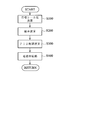
- FIG. 2 is a subroutine flowchart showing an overall processing procedure of the rail pressure control executed by the control unit 6, and the schematic processing procedure of the rail pressure control will be described below with reference to FIG.
- the target rail pressure in the common rail 1 is calculated and calculated based on the engine speed and the command injection amount Q (see step S100 in FIG. 2).
- the command injection amount Q is calculated by a predetermined arithmetic expression based on the engine speed and the accelerator opening.
- a difference (deviation) between the target rail pressure and the actual rail pressure is calculated and calculated (see step S200 in FIG. 2), and PID control is performed to perform PID feedback control of the opening degree of the solenoid valve 24 so that the calculated deviation becomes zero.
- a calculation is performed, and a control drive signal SVX is generated to control the solenoid valve 24 to an opening according to the calculation result (see step S300 in FIG. 2).
- the electromagnetic valve 24 is driven and controlled by the drive control signal SVX generated as described above (step S400 in FIG. 2), and feedback control is performed so that the fuel pressure (actual rail pressure) in the common rail 1 becomes the target rail pressure. Is realized.
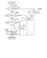
- FIG. 3 shows a procedure of a PID constant setting process that is performed prior to the execution of the PID control calculation described above, and the contents thereof will be described below with reference to FIG.
- the PID constant setting process in the embodiment of the present invention will be schematically described.
- feedback control using PID control is performed as in the prior art. That is, the control amount for the solenoid valve 24 corresponding to the deviation between the actual rail pressure and the target rail pressure is determined by the PID calculation process.
- the solenoid valve 24 is controlled with a control amount calculated by the PID calculation according to the deviation between the actual rail pressure and the target rail pressure. How to set the PID constant is appropriately selected according to the specific conditions of each device.
- FIG. 6 shows an example of discharge characteristics of a high-pressure pump in a conventional apparatus. This is a change in the amount of fuel oil discharged from a high pressure pump (corresponding to the high pressure pump 2 in the embodiment of the present invention) with respect to the energizing current of the solenoid valve corresponding to the solenoid valve 24 in the embodiment of the present invention in the conventional apparatus.
- the horizontal axis represents the energization current of the solenoid valve
- the vertical axis represents the discharge amount of the high-pressure pump.
- the change characteristic of the discharge amount of the high-pressure pump tends to vary depending on the magnitude of the maximum rotation speed (drive shaft rotation speed) of the high-pressure pump.
- the characteristic line denoted by reference numeral g6-1 indicates the change in the discharge amount with respect to the energization current of the solenoid valve when the maximum rotational speed Np of the high pressure pump is set to nmax / 4. It is shown.
- the characteristic line denoted by reference numeral g6-2 indicates that the solenoid valve is used when the maximum rotational speed Np of the high-pressure pump is set to nmax / 2 (nmax / 2> nmax / 4).
- the characteristic line denoted by reference numeral g6-3 indicates that the solenoid valve energization current when the maximum rotation speed Np of the high-pressure pump is set to nmax (nmax> nmax / 2>) is used.
- the change of the discharge amount with respect to the is shown.
- these three characteristics g6-1 to g6-3 have areas that partially overlap each other, and the areas are relatively wide. That is, the range from Imax to about I1 (I1 ⁇ Imax) in terms of the energizing current of the solenoid valve and the range from zero to about Va in terms of the discharge amount is any of the three characteristics g6-1 to g6 ⁇ . 3 is also a substantially overlapping range, and the change in discharge amount with respect to the current change in this overlapping range is substantially linear (see the range indicated by reference numeral 11 in FIG. 6).
- the range from I1 to around I2 (I1 ⁇ I2) in terms of the energizing current of the solenoid valve and the range from Va to around Vb (Vb> Va) in terms of the discharge amount are characteristic g6-2 and g6- 3 is an overlapping range.
- the change in the discharge amount with respect to the current change in this overlapping range is almost linear (see the range indicated by reference numeral 12 in FIG. 6).
- the range from I2 to I3 (I2 ⁇ I3) in terms of the energizing current of the solenoid valve and the range from Vb to about Vc (Vc> Vb) in terms of the discharge amount is only the characteristic g6-3.
- the change in the discharge amount with respect to the current change is almost linear (see the range of reference numeral 13 in FIG. 6).
- the location where the solenoid valve energization current I3 and the high-pressure pump discharge amount Vc are changed from the range in which the change in the discharge amount to the solenoid valve energization current is almost proportional in the characteristic g6-3. It is a position that is almost close to the inflection point.
- the straight line portion (g6-3 straight line portion) indicated by reference numeral 13 in FIG. 6 is stored as a representative characteristic of the three characteristics g6-1 to g6-3, and the solenoid valve (main The PID control constant is determined for each main rotation speed of the high-pressure pump, as shown in FIG. 7 as an example. And used for PID control calculation.
- the discharge characteristics as shown in FIG. 6 are not always obtained, and for example, the discharge characteristics as shown in FIG. 4 may be obtained.
- Such discharge characteristics can be obtained, for example, when the high-pressure pump is driven at a rotational speed that exceeds the originally planned rotational speed or when the range in which the discharge characteristics overlap for each maximum rotational speed is the example shown in FIG. This is the case when there are relatively few cases.
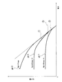
- a characteristic line denoted by reference numeral g4-1 indicates a change in the discharge amount with respect to the energizing current of the solenoid valve 24 when the maximum rotation speed Np of the high pressure pump 2 is set to nmax / 4.
- the characteristic line marked with g4-2 indicates the discharge amount with respect to the energizing current of the solenoid valve 24 when the maximum rotation speed Np of the high pressure pump 2 is set to nmax / 2 (nmax / 2> nmax / 4).
- the change is indicated by a characteristic line denoted by g4-3.
- the discharge amount with respect to the energizing current of the solenoid valve 24 when the maximum rotational speed Np of the high-pressure pump 2 is set to nmax (nmax> nmax / 2>).
- the deviation from each of the characteristics g4-1 to g4-3 is as small as possible, and even when trying to determine one appropriate representative characteristic that can be used for rail pressure control, Really impossible. Also, if a representative characteristic that is as small as possible is determined within a range in which the deviation from each of the characteristics g4-1 to g4-3 can be made by the least square method or the like, and a rail pressure control is performed by setting a PID control constant for this. It is difficult to obtain rail pressure control characteristics that can withstand practical use.
- the rail pressure control method provides stable rail pressure control even when the slope of the change characteristic of the discharge amount with respect to the energization current of the solenoid valve differs depending on the rotation speed of the high-pressure pump.
- a threshold is set for the discharge amount of the high-pressure pump, and the rail pressure control is executed by switching the PID control constant according to the discharge amount. is there.
- the discharge characteristic of the high-pressure pump 2 that is, the change characteristic of the amount of fuel oil discharged with respect to the change in the energization current of the electromagnetic valve 24 varies depending on the rotational speed. That is, the discharge characteristics differ depending on the maximum rotation speed of the high-pressure pump 2.
- the characteristic lines denoted by reference numerals g 4-1 to g 4-3 in FIG. As described above, it is assumed that three types of discharge characteristics for the three maximum rotation speeds are known in advance.
- the horizontal axis represents the energization current of the electromagnetic valve 24, and the vertical axis represents the discharge amount of the high-pressure pump 2.
- a characteristic line denoted by reference numeral g 4-1 (hereinafter referred to as “characteristic line g 4-1”) is a discharge characteristic when the maximum rotation speed Np of the high-pressure pump 2 is set to nmax / 4.
- the characteristic line to which the symbol g4-2 is attached (hereinafter referred to as “characteristic line g4-2”) sets the maximum rotational speed Np of the high-pressure pump 2 to nmax / 2 (nmax / 2> nmax / 4).
- characteristic line g4-3 indicates the maximum rotational speed Np of the high-pressure pump 2 as nmax (nmax> nmax / 2>) is a discharge characteristic when used.
- the first reference discharge amount V1 is the point at which the slope of the characteristic line changes when the current of the solenoid valve 24 is decreased from the maximum value on the characteristic line g4-1 in FIG. This is an amount corresponding to the discharge amount at the (curved point).
- This inflection point will be described using the characteristic line g4-2 in FIG. 4 as an example.
- the dotted line with the circled number 2 indicates that the discharge amount increases as the energization current decreases starting from the point of the maximum energization current at which the discharge amount becomes zero in the characteristic line g4-2.
- This is a tangent line that touches the rising portion of the starting characteristic line g4-2 (hereinafter referred to as “tangent line 2”).
- the characteristic line g4-2 changes in a direction in which the slope of the characteristic line g4-2 becomes smaller as the discharge amount further increases from the slope range of the tangent 2 described above.
- the dotted straight line marked with 1 is a tangent line that touches the new slope of the characteristic line g4-2 (hereinafter referred to as "tangent line 1").
- the intersection of the tangent line 1 and the tangent line 2 is the inflection point in the region where the discharge amount is the smallest among the inflection points of the characteristic line g4-2, and the discharge amount at this inflection point is the reference discharge amount. It becomes.
- the inflection point is not only one inflection point obtained as described above in any of the characteristic lines g4-1 to g4-3. However, in the embodiment of the present invention, the discharge amount is Only the point that appears first in the process of increasing from zero was used.
- the dotted straight line marked with the circle numeral 3 is a straight line that passes through the intersection of the tangent line 1 and the tangent line 2 and is parallel to the horizontal axis of FIG.
- the discharge amount at the intersection with the vertical axis when extending in the axial direction is the reference discharge amount, and in particular, it is referred to as the “second reference discharge amount” because it is the reference discharge amount on the characteristic line g4-2.
- the reference discharge amount in the characteristic line g4-1 is referred to as “first reference discharge amount”, and “V1” is used as the notation, and the reference discharge amount in the characteristic line g4-3 is referred to as “third reference discharge amount”. ", And the notation is” V3 ".
- step S504 when it is determined in step S502 that the discharge amount is equal to or less than the first reference discharge amount V1 (in the case of YES), a PID constant suitable for this discharge amount range (hereinafter referred to as “first” for convenience).
- first a PID constant suitable for this discharge amount range
- step P504 in FIG. 3 the first PID constant selected in advance in the characteristic line g4-1 based on the discharge characteristic at the first reference discharge amount V1 or less and stored in a predetermined storage area of the control unit 6 is read out.
- the PID constant used for PID control at this time is set and used for PID control.
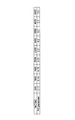
- the PID constant is determined for each rotation speed 500 (rpm) between the rotation speed 500 (rpm) and the rotation speed 4500 (rpm).
- the total of PID constants for each rotation speed at the first reference discharge amount is the first PID constant
- the total of PID constants for each rotation speed at the second reference discharge amount is the second PID constant
- the total PID constant for each rotation speed at the third reference discharge amount is the third PID constant
- the total PID constant for each rotation speed at the discharge amount exceeding the third reference discharge amount is the fourth PID constant.
- Each constant shown in FIG. 5 is merely an example, and the PID constant has an optimum value that varies depending on specific conditions of the vehicle such as the scale of the engine. The optimum value should be selected based on the results of tests and the like.
- step S502 When it is determined in step S502 that the discharge amount is not equal to or less than the first reference discharge amount V1 (in the case of NO), the discharge amount exceeds the first reference discharge amount V1 and the second reference discharge amount V2 is reached. It is determined whether or not it is within the following range (see step S506 in FIG. 3). If it is determined that the discharge amount exceeds the first reference discharge amount V1 and is not more than the second reference discharge amount V2 (in the case of YES), the second PID constant is set. (Refer to Step S508 in FIG. 3).
- the discharge amount exceeds the first reference discharge amount V1 and is selected in advance based on the discharge characteristics in the range of the second reference discharge amount V2 or less, and the control unit 6 stores the predetermined amount.
- the second PID constant stored in the area is read out, set as a PID constant used for PID control at this time, and used for PID control.
- step S506 determines whether or not the discharge amount exceeds the first reference discharge amount V1 and is not in the range of the second reference discharge amount V2 or less (in the case of NO). Then, it is determined whether or not the discharge amount exceeds the second reference discharge amount V2 and is in the range of the third reference discharge amount V3 or less. Then, when it is determined that the discharge amount exceeds the second reference discharge amount V2 and is in the range of the third reference discharge amount V3 or less (in the case of YES), the third PID constant is set. (Refer to step S512 in FIG. 3).
- the discharge amount exceeds the second reference discharge amount V2 and is selected in advance based on the discharge characteristic in the range of the third reference discharge amount V3 or less.
- the third PID constant stored in the area is read out, set as a PID constant used for PID control at this time, and used for PID control.
- the discharge amount is the third amount.
- the fourth PID constant is set (see step S514 in FIG. 3). That is, among the characteristic line g4-3, the fourth PID constant selected in advance based on the discharge characteristic in a range where the discharge amount exceeds the third reference discharge amount V3 and stored in a predetermined storage area of the control unit 6 Is read out, set as a PID constant for PID control at this time, and used for PID control.
- a main routine (refer FIG. 2).
- the PID constant is switched in accordance with the changing discharge characteristic of the high-pressure pump 2, so that it is ensured that rail pressure control using an inappropriate PID constant is performed. Therefore, the rail pressure control with high stability and reliability can be obtained.
- one standard characteristic selected in advance as a discharge characteristic of the high-pressure pump 2 is stored in the control unit 6 and is generally used for rail pressure control. This is based on the premise that the actual discharge characteristics do not change significantly from the standard characteristics, but in reality, the discharge characteristics may change due to rotation.
- a plurality of representative discharge characteristics are stored in the control unit 6 so as to cope with such a case, and the plurality of discharge characteristics are used for rail pressure control.
- FIG. 8 shows an example of a plurality of ejection characteristics, which will be described below with reference to FIG.
- the horizontal axis represents the energization current of the electromagnetic valve 24, and the vertical axis represents the discharge amount of the high-pressure pump 2.
- a characteristic line denoted by g8-1 is a discharge characteristic when the maximum rotation speed Np of the high-pressure pump 2 is set to nmax / 4, and a characteristic denoted by g8-2.
- the line shows the discharge characteristics when the maximum rotational speed Np of the high-pressure pump 2 is set to nmax / 2 (nmax / 2> nmax / 4).
- the characteristic line marked with g8-3 is the high-pressure pump This is a discharge characteristic when the maximum rotation speed Np of the pump 2 is set to nmax (nmax> nmax / 2>).
- Each of these characteristics is pre-stored in a predetermined storage area of the control unit 6 as a so-called map, and a suitable map is selected according to the maximum number of rotations of the high-pressure pump 2 in the operating state. Therefore, it is preferable that the energization control of the electromagnetic valve 24 is performed.
Landscapes
- Engineering & Computer Science (AREA)
- Chemical & Material Sciences (AREA)
- Combustion & Propulsion (AREA)
- Mechanical Engineering (AREA)
- General Engineering & Computer Science (AREA)
- Fuel-Injection Apparatus (AREA)
- Electrical Control Of Air Or Fuel Supplied To Internal-Combustion Engine (AREA)
Abstract
高圧ポンプの吐出特性が、高圧ポンプの回転数によって変化する場合であっても適切なレール圧制御を可能とする。 コモンレール1へ高圧燃料を圧送する高圧ポンプ2への燃料流入量を調整可能に設けられた流入量調整用の電磁弁24を、コモンレール1の実レール圧と目標レール圧との偏差に応じたPIDフィードバック制御によって駆動制御することにより目標レール圧を得られるよう構成されてなるコモンレール式燃料噴射制御装置において、高圧ポンプ2の吐出量に応じて、PID制御におけるPID定数の切り替えを行い、高圧ポンプ2の吐出特性の変化に対応可能として、安定性、信頼性の高いレール圧制御を可能としたものである。
Description
本発明は、コモンレール式燃料噴射制御装置におけるレール圧制御に関し、特に、レール圧制御の安定性、信頼性の向上等を図ったものに関する。
車両用内燃機関のためのコモンレール式燃料噴射制御装置は、コモンレールに蓄積された高圧燃料を、所定の噴射タイミングで燃料噴射弁により内燃機関の気筒内に噴射するよう構成されてなるものであり、近年、広く実用に供されている。
かかるコモンレール式燃料噴射制御装置において、コモンレール圧(レール圧)の制御は、燃料噴射特性の良否に直接に関係するため、如何に安定性、信頼性のある制御を行うか重要であり、そのような観点などから種々の制御方法が提案されている。
かかるコモンレール式燃料噴射制御装置において、コモンレール圧(レール圧)の制御は、燃料噴射特性の良否に直接に関係するため、如何に安定性、信頼性のある制御を行うか重要であり、そのような観点などから種々の制御方法が提案されている。
例えば、コモンレールの上流側に設けられた高圧ポンプのプランジャ室へ送り込む燃料の流量を、電磁比例式バルブによって制御できるようにし、エンジンが要求する燃料圧力となるように高圧ポンプのプランジャ室への燃料の流量を、その電磁比例式バルブによって調整することで所望のレール圧が得られるようにした方式等が種々提案されている(例えば、特許文献1等参照)。
ところで、上述のように電磁比例式バルブを用いて高圧ポンプのプランジャ室へ送り込む燃料の流量を調整することで、レール圧を制御するように構成された燃料噴射制御装置においては、電磁比例式バルブの通電電流に対する高圧ポンプの燃料の吐出量の変化特性の代表的なものをマップ化して標準特性として記憶し、これに基づいて、走行状態などから要求されるレール圧となるよう電磁比例式バルブへの通電を制御する方式などが採られる。さらに、この場合、電磁比例式バルブの通電制御をいわゆるPID制御で行うようにすると共に、PID制御に学習制御を適用することで、上述のマップ化された標準特性と、実際の電磁式比例バルブの通電流に対する高圧ポンプの吐出量の変化特性のばらつきに対処できるようにするなどの手法も比較的良く用いられている。
しかしながら、高圧ポンプの駆動条件が、マップ化された標準特性における駆動条件と極端に異なる状況となった場合や、高圧ポンプ自体のばらつき等によって、実際の電磁式比例バルブの通電流に対する高圧ポンプの吐出量の変化特性が標準特性と大きくことなる虞があり、最悪時には、十分なレール圧制御が得られなくなるという問題がある。
特開2005-113704号公報
本発明は、上記実状に鑑みてなされたもので、高圧ポンプの吐出特性が、高圧ポンプの回転数によって変化する場合であっても適切なレール圧制御を可能とするレール圧制御方法及びコモンレール式燃料噴射制御装置を提供するものである。
本発明の第1の形態によれば、コモンレールへ高圧燃料を圧送する高圧ポンプへの燃料流入量を調整可能に設けられた流入量調整用の電磁弁を、前記コモンレールのレール圧を目標レール圧とすべく、前記コモンレールの実レール圧と目標レール圧との偏差に応じたPIDフィードバック制御によって駆動制御することにより前記高圧ポンプの吐出量を制御して前記コモンレールのレール圧を目標レール圧に制御可能に構成されてなるコモンレール式燃料噴射制御装置におけるレール圧制御方法であって、
前記高圧ポンプの吐出量に応じて、前記PID制御におけるPID定数の切り替えを行い、前記高圧ポンプの吐出特性の変化に対応可能に構成されてなるレール圧制御方法が提供される。
本発明の第2の形態によれば、コモンレールへ高圧燃料を圧送する高圧ポンプへの燃料流入量を調整可能に設けられた流入量調整用の電磁弁を、制御ユニットにより、前記コモンレールのレール圧を目標レール圧とすべく、前記コモンレールの実レール圧と目標レール圧との偏差に応じたPIDフィードバック制御により駆動制御し、前記高圧ポンプの吐出量を制御して前記コモンレールのレール圧を目標レール圧に制御可能に構成されてなるコモンレール式燃料噴射制御装置であって、
前記制御ユニットは、前記高圧ポンプの吐出量に応じて、前記PID制御におけるPID定数の切り替えを行うよう構成されてなり、前記高圧ポンプの吐出特性の変化に対応可能に構成されてなるコモンレール式燃料噴射制御装置が提供される。
前記高圧ポンプの吐出量に応じて、前記PID制御におけるPID定数の切り替えを行い、前記高圧ポンプの吐出特性の変化に対応可能に構成されてなるレール圧制御方法が提供される。
本発明の第2の形態によれば、コモンレールへ高圧燃料を圧送する高圧ポンプへの燃料流入量を調整可能に設けられた流入量調整用の電磁弁を、制御ユニットにより、前記コモンレールのレール圧を目標レール圧とすべく、前記コモンレールの実レール圧と目標レール圧との偏差に応じたPIDフィードバック制御により駆動制御し、前記高圧ポンプの吐出量を制御して前記コモンレールのレール圧を目標レール圧に制御可能に構成されてなるコモンレール式燃料噴射制御装置であって、
前記制御ユニットは、前記高圧ポンプの吐出量に応じて、前記PID制御におけるPID定数の切り替えを行うよう構成されてなり、前記高圧ポンプの吐出特性の変化に対応可能に構成されてなるコモンレール式燃料噴射制御装置が提供される。
本発明によれば、PID定数を吐出量によって切り替えるように構成することで、高圧ポンプの吐出特性が本来予定していた特性から大きく変化した場合に不適切なPID定数がそのまま用いられてレール圧制御が実行されるようなことが回避でき、適切なPID定数を用いたレール圧制御が可能となり、従来に比して、安定性、信頼性の高いレール圧制御を得ることができるという効果を奏するものである。
1…コモンレール
2…高圧ポンプ
3-1~3-N…燃料噴射弁
6…制御ユニット
10…ディーゼルエンジン
2…高圧ポンプ
3-1~3-N…燃料噴射弁
6…制御ユニット
10…ディーゼルエンジン
以下、本発明の実施の形態について、図1乃至図5及び図8を参照しつつ説明する。
なお、以下に説明する部材、配置等は本発明を限定するものではなく、本発明の趣旨の範囲内で種々改変することができるものである。
最初に、本発明の実施の形態における内燃機関の燃料噴射制御方法が適用される燃料噴射制御装置の構成例について、図1を参照しつつ説明する。
本発明の実施の形態の燃料噴射制御装置Sは、内燃機関としてのディーゼルエンジン10を備えた自動車両において、ディーゼルエンジン10への燃料の噴射供給を制御するためのコモンレール式式燃料噴射制御装置が構成されてなるものである。
なお、以下に説明する部材、配置等は本発明を限定するものではなく、本発明の趣旨の範囲内で種々改変することができるものである。
最初に、本発明の実施の形態における内燃機関の燃料噴射制御方法が適用される燃料噴射制御装置の構成例について、図1を参照しつつ説明する。
本発明の実施の形態の燃料噴射制御装置Sは、内燃機関としてのディーゼルエンジン10を備えた自動車両において、ディーゼルエンジン10への燃料の噴射供給を制御するためのコモンレール式式燃料噴射制御装置が構成されてなるものである。
すなわち、本発明の実施の形態の燃料噴射制御装置Sは、高圧燃料が蓄積されるコモンレール1と、このコモンレール1へ高圧燃料を供給する高圧ポンプ2と、コモンレール1に蓄積された高圧燃料をディーゼルエンジン10の各気筒11-1~11-Nへ噴射する複数の燃料噴射弁3-1~3-Nと、制御ユニット(図1においては「ECU」と表記)6を主たる構成要素として構成されてなるものである。
高圧ポンプ2は、ディーゼルエンジン10によって駆動される高圧ポンプ本体21と、フューエルメタリングユニット22と、インレット・アウトレットバルブ26とに大別されて構成されたもので、これらが一体に組み立てられてなるものである。なお、高圧ポンプ2は、ディーゼルエンジン10と直結されているが、回転数の比率は、高圧ポンプ2の設定によって必ずしも1:1となるものではない。
フューエルメタリングユニット22には、燃料タンク4からの燃料がフィードポンプ5によって供給されるようになっている。
フューエルメタリングユニット22には、燃料タンク4からの燃料がフィードポンプ5によって供給されるようになっている。
フューエルメタリングユニット22は、電磁式比例バルブを用いてなるもので、フィードポンプ5から供給された燃料油を高圧ポンプ本体21内のプランジャ室へ送り込むためのもので、そのプランジャ室への燃料油の送り込みは、フューエルメタリングユニット22内に設けられた電磁弁24の開閉制御によって行われるものとなっている。
すなわち、電磁弁24の開閉制御により、高圧ポンプ本体21からコモンレール1へ流れる高圧燃料の流量が調整され、その流量調整によってコモンレール1内の高圧燃料の圧力を所定の圧力(目標レール圧)に制御できるようになっている。
すなわち、電磁弁24の開閉制御により、高圧ポンプ本体21からコモンレール1へ流れる高圧燃料の流量が調整され、その流量調整によってコモンレール1内の高圧燃料の圧力を所定の圧力(目標レール圧)に制御できるようになっている。
かかる電磁弁24の開閉制御は、制御ユニット6によって生成される駆動制御信号SVXによって行われるようになっており、制御ユニット6においては、レール圧制御処理の実行により、コモンレール1における燃料圧力が、ディーゼルエンジン10の動作状況に対応した要求噴射量に応じた圧力となるように駆動制御信号SVXが生成されるものとなっている。
なお、フューエルメタリングユニット22の燃料油は、インレット・アウトレットバルブ26を介して、高圧ポンプ2のプランジャ室(図示せず)に送出され、プランジャ室で高圧にされた後、コモンレール1へ供給されるようになっている。
一方、燃料噴射弁3-1~3-Nは、それぞれ噴射制御用の電磁弁V1~VNを備えており、これら電磁弁V1~VNは、制御ユニット6から出力される開閉成信号SV1~SVNに応じてそれぞれ独立して開閉制御されて、対応する気筒内に高圧燃料が所要のタイミングで所要量だけ噴射されるよう動作制御されるものとなっている。
制御ユニット6は、例えば、公知・周知の構成を有してなるマイクロコンピュータ(図示せず)を中心に、RAMやROM等の記憶素子(図示せず)を有すると共に、電磁弁V1~VNの開閉成制御のための開閉成信号SV1~SVNを生成、出力する回路(図示せず)や、電磁弁24の駆動制御信号SVXを生成、出力する回路等を主たる構成要素として構成されたものとなっている。
この制御ユニット6には、回転センサ7により検出されたディーゼルエンジン10の回転数に対応した回転信号Nや、アクセルセンサ8により検出されたアクセル(図示せず)の踏み込み量(アクセル開度)に対応したアクセル開度信号A、さらには、圧力センサ9によって検出されたコモンレール1内の燃料圧力PAなどが入力されて、これら種々の入力信号に基づいて燃料噴射制御や本発明の実施の形態におけるレール圧制御(詳細は後述)が実行されるようになっている。
この制御ユニット6には、回転センサ7により検出されたディーゼルエンジン10の回転数に対応した回転信号Nや、アクセルセンサ8により検出されたアクセル(図示せず)の踏み込み量(アクセル開度)に対応したアクセル開度信号A、さらには、圧力センサ9によって検出されたコモンレール1内の燃料圧力PAなどが入力されて、これら種々の入力信号に基づいて燃料噴射制御や本発明の実施の形態におけるレール圧制御(詳細は後述)が実行されるようになっている。
図2には、制御ユニット6により実行されるレール圧制御の全体の概略処理手順がサブルーチンフローチャートに示されており、以下、同図を参照しつつ、レール圧制御の概略処理手順について説明する。
制御ユニット6においては、エンジン回転数と指示噴射量Qに基づいて、コモンレール1における目標レール圧が演算算出されるものとなっている(図2のステップS100参照)。なお、指示噴射量Qは、エンジン回転数とアクセル開度に基づいて所定の演算式により算出されるものとなっている。
制御ユニット6においては、エンジン回転数と指示噴射量Qに基づいて、コモンレール1における目標レール圧が演算算出されるものとなっている(図2のステップS100参照)。なお、指示噴射量Qは、エンジン回転数とアクセル開度に基づいて所定の演算式により算出されるものとなっている。
次いで、目標レール圧と実レール圧の差(偏差)が演算算出され(図2のステップS200参照)、算出された偏差が零となるよう電磁弁24の開度をPIDフィードバック制御するためPID制御演算が行われ、電磁弁24をその演算結果に応じた開度に制御すべく制御駆動信号SVXが生成されることとなる(図2のステップS300参照)。
そして、上述のようにして生成された駆動制御信号SVXによって電磁弁24が駆動制御され(図2のステップS400)、コモンレール1内の燃料圧力(実レール圧)が目標レール圧となるようフィードバック制御が実現されるものとなっている。
そして、上述のようにして生成された駆動制御信号SVXによって電磁弁24が駆動制御され(図2のステップS400)、コモンレール1内の燃料圧力(実レール圧)が目標レール圧となるようフィードバック制御が実現されるものとなっている。
図3には、上述したPID制御演算の実行に先立って行われるPID定数設定処理の手順がサブルーチンフローチャートに示されており、以下、同図を参照しつつ、その内容について説明する。
最初に、本発明の実施の形態におけるPID定数設定処理について概略的に説明する。
先に説明したように本発明の実施の形態のレール圧制御においては、従来同様、PID制御を用いたフィードバック制御が行われるようになっている。
すなわち、実際のレール圧と目標レール圧の偏差に応じた電磁弁24に対する制御量がPID演算処理によって定められるようになっている。
最初に、本発明の実施の形態におけるPID定数設定処理について概略的に説明する。
先に説明したように本発明の実施の形態のレール圧制御においては、従来同様、PID制御を用いたフィードバック制御が行われるようになっている。
すなわち、実際のレール圧と目標レール圧の偏差に応じた電磁弁24に対する制御量がPID演算処理によって定められるようになっている。
PID演算処理においては、実際のレール圧と目標レール圧の偏差に応じてPID演算によって算出された制御量で電磁弁24が制御されるようになっている。
PID定数を、どのように設定するかは、個々の装置の具体的な条件等によって適宜選択されるものである。
PID定数を、どのように設定するかは、個々の装置の具体的な条件等によって適宜選択されるものである。
このようなPID定数は、従来装置にあっては、次述するように設定された一種類の固定値が用いられていた。
まず、レール圧制御のためのPID定数を設定するにあたっては、電磁弁24の通電電流に対する高圧ポンプ2からの燃料油の吐出量の変化特性が考慮される。
図6には、従来装置における高圧ポンプの吐出特性の一例が示されている。
これは、従来装置において、本発明の実施の形態における電磁弁24に相当する電磁弁の通電電流に対する高圧ポンプ(本発明の実施の形態における高圧ポンプ2に相当)の燃料油の吐出量の変化特性を示すもので、同図において、横軸は電磁弁の通電電流を、縦軸は高圧ポンプの吐出量を、それぞれ表している。
まず、レール圧制御のためのPID定数を設定するにあたっては、電磁弁24の通電電流に対する高圧ポンプ2からの燃料油の吐出量の変化特性が考慮される。
図6には、従来装置における高圧ポンプの吐出特性の一例が示されている。
これは、従来装置において、本発明の実施の形態における電磁弁24に相当する電磁弁の通電電流に対する高圧ポンプ(本発明の実施の形態における高圧ポンプ2に相当)の燃料油の吐出量の変化特性を示すもので、同図において、横軸は電磁弁の通電電流を、縦軸は高圧ポンプの吐出量を、それぞれ表している。
高圧ポンプの吐出量の変化特性は、高圧ポンプの最大回転数(ドライブシャフトの回転数)を如何なる大きさに設定して用いるかによって異なる傾向にある。
例えば、図6の例において、符号g6-1が付された特性線は、高圧ポンプの最大回転数Npをnmax/4に設定して使用した場合の電磁弁の通電電流に対する吐出量の変化を示すものである。
また、図6の例において、符号g6-2が付された特性線は、高圧ポンプの最大回転数Npをnmax/2(nmax/2>nmax/4)に設定して使用した場合の電磁弁の通電電流に対する吐出量の変化を示すものである。
さらに、図6の例において、符号g6-3が付された特性線は、高圧ポンプの最大回転数Npをnmax(nmax>nmax/2>)に設定して使用した場合の電磁弁の通電電流に対する吐出量の変化を示すものである。
例えば、図6の例において、符号g6-1が付された特性線は、高圧ポンプの最大回転数Npをnmax/4に設定して使用した場合の電磁弁の通電電流に対する吐出量の変化を示すものである。
また、図6の例において、符号g6-2が付された特性線は、高圧ポンプの最大回転数Npをnmax/2(nmax/2>nmax/4)に設定して使用した場合の電磁弁の通電電流に対する吐出量の変化を示すものである。
さらに、図6の例において、符号g6-3が付された特性線は、高圧ポンプの最大回転数Npをnmax(nmax>nmax/2>)に設定して使用した場合の電磁弁の通電電流に対する吐出量の変化を示すものである。
この例の場合、これら3つの特性g6-1~g6-3は、その一部が互いに重複する領域があり、その領域は比較的広いものとなっている。すなわち、電磁弁の通電電流で言えば、Imaxから大凡I1(I1<Imax)付近まで、吐出量で言えば、零から大凡Va付近までの範囲は、3つのいずれの特性g6-1~g6-3もほぼ重複する範囲となっており、この重複範囲における電流変化に対する吐出量の変化は、ほぼ直線的なものとなっている(図6の符号l1の範囲参照)。
ここで、電磁弁の通電電流I1、高圧ポンプの吐出量Vaとなる箇所は、特性g6-1において、電磁弁の通電電流に対する吐出量の変化がほぼ比例する範囲から曲線的な変化に変わりつつある位置、いわば変曲点にほぼ近い位置となっている。
次いで、電磁弁の通電電流で言えば、I1からI2(I1<I2)付近まで、吐出量で言えば、Vaから大凡Vb(Vb>Va)付近までの範囲は、特性g6-2及びg6-3がほぼ重複する範囲となっている。そして、この重複範囲における電流変化に対する吐出量の変化は、ほぼ直線的なものとなっている(図6の符号l2の範囲参照)。
ここで、電磁弁の通電電流I2、高圧ポンプの吐出量Vbとなる箇所は、特性g6-2において、電磁弁の通電電流に対する吐出量の変化がほぼ比例する範囲から曲線的な変化に変わりつつある位置、いわば変曲点にほぼ近い位置となっている。
ここで、電磁弁の通電電流I2、高圧ポンプの吐出量Vbとなる箇所は、特性g6-2において、電磁弁の通電電流に対する吐出量の変化がほぼ比例する範囲から曲線的な変化に変わりつつある位置、いわば変曲点にほぼ近い位置となっている。
そして、電磁弁の通電電流で言えば、I2からI3(I2<I3)付近まで、吐出量で言えば、Vbから大凡Vc(Vc>Vb)付近までの範囲は、特性g6-3のみが、電流変化に対する吐出量の変化がほぼ直線的なものとなっている(図6の符号l3の範囲参照)。
ここで、電磁弁の通電電流I3、高圧ポンプの吐出量Vcとなる箇所は、特性g6-3において、電磁弁の通電電流に対する吐出量の変化がほぼ比例する範囲から曲線的な変化に変わりつつある位置、いわば変曲点にほぼ近い位置となっている。
ここで、電磁弁の通電電流I3、高圧ポンプの吐出量Vcとなる箇所は、特性g6-3において、電磁弁の通電電流に対する吐出量の変化がほぼ比例する範囲から曲線的な変化に変わりつつある位置、いわば変曲点にほぼ近い位置となっている。
このような従来特性の場合、図6において符号l3で表された直線部分(g6-3の直線部分)を、3つの特性g6-1~g6-3の代表特性として記憶し、電磁弁(本発明の電磁弁24に相当)の通電電流を定めると共に、PID制御定数は、図7に一例が示されたように、高圧ポンプの主要な回転数に対して、それぞれ一つのPID定数が定められ、PID制御演算に用いられるものとなっていた。
ところが、常に図6に示されたような吐出特性が得られるとは限らず、例えば、図4に示されたような吐出特性となる場合もある。
このような吐出特性となるのは、例えば、本来予定している回転数を超える回転数で高圧ポンプが駆動された場合や、もともと最大回転数毎の吐出特性の重複する範囲が図6の例に比して比較的少ない場合などである。
同図において、符号g4-1が付された特性線は、高圧ポンプ2の最大回転数Npをnmax/4に設定して使用した場合の電磁弁24の通電電流に対する吐出量の変化を、符号g4-2が付された特性線は、高圧ポンプ2の最大回転数Npをnmax/2(nmax/2>nmax/4)に設定して使用した場合の電磁弁24の通電電流に対する吐出量の変化を、符号g4-3が付された特性線は、高圧ポンプ2の最大回転数Npをnmax(nmax>nmax/2>)に設定して使用した場合の電磁弁24の通電電流に対する吐出量の変化を、それぞれ示したものである。
このような吐出特性となるのは、例えば、本来予定している回転数を超える回転数で高圧ポンプが駆動された場合や、もともと最大回転数毎の吐出特性の重複する範囲が図6の例に比して比較的少ない場合などである。
同図において、符号g4-1が付された特性線は、高圧ポンプ2の最大回転数Npをnmax/4に設定して使用した場合の電磁弁24の通電電流に対する吐出量の変化を、符号g4-2が付された特性線は、高圧ポンプ2の最大回転数Npをnmax/2(nmax/2>nmax/4)に設定して使用した場合の電磁弁24の通電電流に対する吐出量の変化を、符号g4-3が付された特性線は、高圧ポンプ2の最大回転数Npをnmax(nmax>nmax/2>)に設定して使用した場合の電磁弁24の通電電流に対する吐出量の変化を、それぞれ示したものである。
このような吐出特性の場合、上述したと同様に、各特性g4-1~g4-3との偏差が極力小さく、レール圧制御に用いることのできる適切な代表特性を一つ定めようとしても、現実的に無理がある。
また、仮に、最小二乗法などにより各特性g4-1~g4-3との偏差が可能な範囲で極力小さい代表特性を定め、これに対してPID制御定数を定めてレール圧制御を行っても、実用に耐え得るレール圧制御特性を得ることは困難である。
また、仮に、最小二乗法などにより各特性g4-1~g4-3との偏差が可能な範囲で極力小さい代表特性を定め、これに対してPID制御定数を定めてレール圧制御を行っても、実用に耐え得るレール圧制御特性を得ることは困難である。
本発明の実施の形態におけるレール圧制御方法は、こように高圧ポンプの回転数によって、電磁弁の通電電流に対する吐出量の変化特性の傾きが異なる場合であっても、安定したレール圧制御を可能とするもので、概括的には、高圧ポンプの吐出量について、しきい値を定めて、吐出量に応じてPID制御定数を切り替えるようにして、レール圧制御を実行するようにしたものである。
以下、図3を参照しつつ、具体的な処理手順について説明する。
制御ユニット6により、処理が開始されると、最初に、吐出量が第1の基準吐出量V1以下であるか否かが判定される(図3のステップS502参照)。
ここで、第1の基準吐出量V1について図4を参照しつつ説明する。
例えば、本発明の実施の形態において、高圧ポンプ2の吐出特性、すなわち、電磁弁24の通電電流の変化に対する吐出される燃料油量の変化特性は、回転数によって異なるものである。すなわち、高圧ポンプ2を如何なる最大回転数で用いるかによってその吐出特性が異なり、本発明の実施の形態においては、例えば、図4において符号g4-1~g4-3が付された特性線で表されたように、3つの最大回転数に対する3種類の吐出特性が予め把握されていると仮定する。
なお、図4において、横軸は電磁弁24の通電電流を、縦軸は高圧ポンプ2の吐出量を、それぞれ表している。
制御ユニット6により、処理が開始されると、最初に、吐出量が第1の基準吐出量V1以下であるか否かが判定される(図3のステップS502参照)。
ここで、第1の基準吐出量V1について図4を参照しつつ説明する。
例えば、本発明の実施の形態において、高圧ポンプ2の吐出特性、すなわち、電磁弁24の通電電流の変化に対する吐出される燃料油量の変化特性は、回転数によって異なるものである。すなわち、高圧ポンプ2を如何なる最大回転数で用いるかによってその吐出特性が異なり、本発明の実施の形態においては、例えば、図4において符号g4-1~g4-3が付された特性線で表されたように、3つの最大回転数に対する3種類の吐出特性が予め把握されていると仮定する。
なお、図4において、横軸は電磁弁24の通電電流を、縦軸は高圧ポンプ2の吐出量を、それぞれ表している。
図4において、符号g4-1が付された特性線(以下「特性線g4-1」と称する)は、高圧ポンプ2の最大回転数Npをnmax/4に設定して使用した場合の吐出特性であり、符号g4-2が付された特性線(以下「特性線g4-2」と称する)は、高圧ポンプ2の最大回転数Npをnmax/2(nmax/2>nmax/4)に設定して使用した場合の吐出特性であり、符号g4-3が付された特性線(以下「特性線g4-3」と称する)は、高圧ポンプ2の最大回転数Npをnmax(nmax>nmax/2>)に設定して使用した場合の吐出特性である。
そして、先の第1の基準吐出量V1は、図4の特性線g4-1において、電磁弁24の電流を最大値から減少させていった際に、特性線の傾きが変化する点(変曲点)における吐出量に相当する量である。
この変曲点について、図4において特性線g4-2を例に採り説明する。
図4において、丸数字の2が付された点線の直線は、特性線g4-2において、吐出量が零となる通電電流最大値の点を起点として、通電電流の減少と共に吐出量が増加し始めた特性線g4-2の立ち上がり部分に接する接線である(以下「接線2」と称する)。
この変曲点について、図4において特性線g4-2を例に採り説明する。
図4において、丸数字の2が付された点線の直線は、特性線g4-2において、吐出量が零となる通電電流最大値の点を起点として、通電電流の減少と共に吐出量が増加し始めた特性線g4-2の立ち上がり部分に接する接線である(以下「接線2」と称する)。
また、図4において、特性線g4-2において、上述の接線2の傾き範囲からさらに吐出量が増加してゆくにつれて、特性線g4-2の傾きは小さくなる方向に変化しており、丸数字の1が付された点線の直線は、その特性線g4-2の新たな傾き部分に接する接線である(以下「接線1」と称する)。
そして、上述の接線1と接線2の交点が、特性線g4-2の変曲点の内、最も吐出量の小さい領域にある変曲点であり、この変曲点における吐出量が基準吐出量となる。
なお、変曲点は、特性線g4-1~g4-3のいずれにおいても、上述のように求められた変曲点一つだけではないが、本発明の実施の形態においては、吐出量が零から増加してゆく過程で最初に現れる点のみを用いるものとした。
そして、上述の接線1と接線2の交点が、特性線g4-2の変曲点の内、最も吐出量の小さい領域にある変曲点であり、この変曲点における吐出量が基準吐出量となる。
なお、変曲点は、特性線g4-1~g4-3のいずれにおいても、上述のように求められた変曲点一つだけではないが、本発明の実施の形態においては、吐出量が零から増加してゆく過程で最初に現れる点のみを用いるものとした。
すなわち、丸数字の3が付された点線の直線は、上述の接線1と接線2の交点を通り、図4の横軸に対して平行する直線であるが、この直線を、図4の縦軸方向へ延長した際に縦軸との交点における吐出量が基準吐出量であり、特に、特性線g4-2における基準吐出量であることから”第2の基準吐出量”と称し、”V2”を以てその表記とする。
同様にして、特性線g4-1における基準吐出量を”第1の基準吐出量”と称し、”V1”を以てその表記とし、特性線g4-3における基準吐出量を”第3の基準吐出量”と称し、”V3”を以てその表記とする。
同様にして、特性線g4-1における基準吐出量を”第1の基準吐出量”と称し、”V1”を以てその表記とし、特性線g4-3における基準吐出量を”第3の基準吐出量”と称し、”V3”を以てその表記とする。
ここで、再び図3におけるレール圧制御処理手順の説明に戻ることとする。
しかして、ステップS502において、吐出量が第1の基準吐出量V1以下であると判定された場合(YESの場合)には、この吐出量の範囲に適するPID定数(以下便宜的に「第1のPID定数」と称する)の設定が行われることとなる(図3のステップS504参照)。
すなわち、特性線g4-1の内、第1の基準吐出量V1以下における吐出特性を基準として予め選定され、制御ユニット6の所定の記憶領域に記憶された第1のPID定数が読み出されて、この時点におけるPID制御に供されるPID定数として設定されてPID制御に用いられることとなる。
このようにしてステップS504の処理が実行された後は、メインルーチン(図2参照)へ一旦戻ることとなる。
しかして、ステップS502において、吐出量が第1の基準吐出量V1以下であると判定された場合(YESの場合)には、この吐出量の範囲に適するPID定数(以下便宜的に「第1のPID定数」と称する)の設定が行われることとなる(図3のステップS504参照)。
すなわち、特性線g4-1の内、第1の基準吐出量V1以下における吐出特性を基準として予め選定され、制御ユニット6の所定の記憶領域に記憶された第1のPID定数が読み出されて、この時点におけるPID制御に供されるPID定数として設定されてPID制御に用いられることとなる。
このようにしてステップS504の処理が実行された後は、メインルーチン(図2参照)へ一旦戻ることとなる。
ここで、PID定数の具体例について、図5を参照しつつ説明する。
図5においては、「10」は、第1の基準吐出量V1の具体数値例を、「40」は、第2の第1の基準吐出量V2の具体数値例を、「80」は、第3の基準吐出量V3の具体数値例を、また、「>80」は、吐出量が第3の基準吐出量V3以上であることを、それぞれ示し、各基準吐出量毎に、ディーゼルエンジン10の主要回転数に対するPID定数の例が示されている。
図5においては、「10」は、第1の基準吐出量V1の具体数値例を、「40」は、第2の第1の基準吐出量V2の具体数値例を、「80」は、第3の基準吐出量V3の具体数値例を、また、「>80」は、吐出量が第3の基準吐出量V3以上であることを、それぞれ示し、各基準吐出量毎に、ディーゼルエンジン10の主要回転数に対するPID定数の例が示されている。
この例においては、回転数500(r.p.m)から回転数4500(r.p.m)間での間、回転数500(r.p.m)毎にPID定数が定められたものとなっており、本発明の実施の形態においては、説明の便宜上、第1の基準吐出量における各回転数に対するPID定数の総体を第1のPID定数、第2の基準吐出量における各回転数に対するPID定数の総体を第2のPID定数、第3の基準吐出量における各回転数に対するPID定数の総体を第3のPID定数と、また、第3の基準吐出量超える吐出量における各回転数に対するPID定数の総体を第4のPID定数と、それぞれ称することとする。
なお、図5に示された各定数は、あくまでも一例であり、PID定数は、エンジンの規模等の車両の具体的な条件によって最適値が異なるもので、かかる具体的条件を加味してシミュレーションや試験等の結果に基づいて最適値が選定されるべきものである。
なお、図5に示された各定数は、あくまでも一例であり、PID定数は、エンジンの規模等の車両の具体的な条件によって最適値が異なるもので、かかる具体的条件を加味してシミュレーションや試験等の結果に基づいて最適値が選定されるべきものである。
ここで、再び図3におけるレール圧制御処理手順の説明に戻ることとする。
ステップS502において、吐出量が第1の基準吐出量V1以下ではないと判定された場合(NOの場合)には、吐出量が第1の基準吐出量V1を超え、第2の基準吐出量V2以下の範囲にあるか否かが判定される(図3のステップS506参照)。
そして、吐出量が第1の基準吐出量V1を超え、第2の基準吐出量V2以下の範囲にあると判定された場合(YESの場合)には、第2のPID定数の設定が行われることとなる(図3のステップS508参照)。
ステップS502において、吐出量が第1の基準吐出量V1以下ではないと判定された場合(NOの場合)には、吐出量が第1の基準吐出量V1を超え、第2の基準吐出量V2以下の範囲にあるか否かが判定される(図3のステップS506参照)。
そして、吐出量が第1の基準吐出量V1を超え、第2の基準吐出量V2以下の範囲にあると判定された場合(YESの場合)には、第2のPID定数の設定が行われることとなる(図3のステップS508参照)。
すなわち、特性線g4-2の内、吐出量が第1の基準吐出量V1を超え、第2の基準吐出量V2以下の範囲における吐出特性を基準として予め選定され、制御ユニット6の所定の記憶領域に記憶された第2のPID定数が読み出されて、この時点におけるPID制御に供されるPID定数として設定されてPID制御に用いられることとなる。
このようにしてステップS508の処理が実行された後は、メインルーチン(図2参照)へ一旦戻ることとなる。
このようにしてステップS508の処理が実行された後は、メインルーチン(図2参照)へ一旦戻ることとなる。
一方、ステップS506において、吐出量は第1の基準吐出量V1を超え、第2の基準吐出量V2以下の範囲にないと判定された場合(NOの場合)には、ステップS510の処理へ進み、吐出量が第2の基準吐出量V2を超え、第3の基準吐出量V3以下の範囲にあるか否かが判定される。
そして、吐出量が第2の基準吐出量V2を超え、第3の基準吐出量V3以下の範囲にあると判定された場合(YESの場合)には、第3のPID定数の設定が行われることとなる(図3のステップS512参照)。
そして、吐出量が第2の基準吐出量V2を超え、第3の基準吐出量V3以下の範囲にあると判定された場合(YESの場合)には、第3のPID定数の設定が行われることとなる(図3のステップS512参照)。
すなわち、特性線g4-3の内、吐出量が第2の基準吐出量V2を超え、第3の基準吐出量V3以下の範囲における吐出特性を基準として予め選定され、制御ユニット6の所定の記憶領域に記憶された第3のPID定数が読み出されて、この時点におけるPID制御に供されるPID定数として設定されてPID制御に用いられることとなる。このようにしてステップS512の処理が実行された後は、メインルーチン(図2参照)へ一旦戻ることとなる。
一方、ステップS510において、吐出量が第2の基準吐出量V2を超え、第3の基準吐出量V3以下の範囲にないと判定された場合(NOの場合)には、吐出量が第3の基準量V3を超えているとして、第4のPID定数の設定が行われることとなる(図3のステップS514参照)。
すなわち、特性線g4-3の内、吐出量が第3の基準吐出量V3を超える範囲における吐出特性を基準として予め選定され、制御ユニット6の所定の記憶領域に記憶された第4のPID定数が読み出されて、この時点におけるPID制御に供されるPID定数として設定されてPID制御に用いられることとなる。このようにしてステップS514の処理が実行された後は、メインルーチン(図2参照)へ一旦戻ることとなる。
一方、ステップS510において、吐出量が第2の基準吐出量V2を超え、第3の基準吐出量V3以下の範囲にないと判定された場合(NOの場合)には、吐出量が第3の基準量V3を超えているとして、第4のPID定数の設定が行われることとなる(図3のステップS514参照)。
すなわち、特性線g4-3の内、吐出量が第3の基準吐出量V3を超える範囲における吐出特性を基準として予め選定され、制御ユニット6の所定の記憶領域に記憶された第4のPID定数が読み出されて、この時点におけるPID制御に供されるPID定数として設定されてPID制御に用いられることとなる。このようにしてステップS514の処理が実行された後は、メインルーチン(図2参照)へ一旦戻ることとなる。
このように、本発明の実施の形態においては、変化する高圧ポンプ2の吐出特性に合わせてPID定数を切り替えるようにしたので、不適切なPID定数を用いたレール圧制御が行われることを確実に回避することができ、安定性、信頼性の高いレール圧制御が得られることとなる。
次に、第2の構成例について、図8を参照しつつ説明する。
従来装置においては、高圧ポンプ2の吐出特性として、予め選定された一つ標準特性が制御ユニット6に記憶され、レール圧制御に用いられる構成が一般的である。これは、実際の吐出特性が標準特性から大きく変化しないことが前提であるが、実際には、回転により吐出特性が変化してしまう場合もあり得る。
第2の構成例は、このような場合に対処できるよう、複数の代表的な吐出特性を制御ユニット6内に記憶し、これら複数の吐出特性をレール圧制御に供するようにしたものである。
従来装置においては、高圧ポンプ2の吐出特性として、予め選定された一つ標準特性が制御ユニット6に記憶され、レール圧制御に用いられる構成が一般的である。これは、実際の吐出特性が標準特性から大きく変化しないことが前提であるが、実際には、回転により吐出特性が変化してしまう場合もあり得る。
第2の構成例は、このような場合に対処できるよう、複数の代表的な吐出特性を制御ユニット6内に記憶し、これら複数の吐出特性をレール圧制御に供するようにしたものである。
図8には、複数の吐出特性の例が示されており、以下、同図を参照しつつ説明する。
図8において、横軸は、電磁弁24の通電電流を、縦軸は高圧ポンプ2の吐出量を、それぞれ表している。
同図において、符号g8-1が付された特性線は、高圧ポンプ2の最大回転数Npをnmax/4に設定して使用した場合の吐出特性であり、符号g8-2が付された特性線は、高圧ポンプ2の最大回転数Npをnmax/2(nmax/2>nmax/4)に設定して使用した場合の吐出特性であり、符号g8-3が付された特性線は、高圧ポンプ2の最大回転数Npをnmax(nmax>nmax/2>)に設定して使用した場合の吐出特性である。
図8において、横軸は、電磁弁24の通電電流を、縦軸は高圧ポンプ2の吐出量を、それぞれ表している。
同図において、符号g8-1が付された特性線は、高圧ポンプ2の最大回転数Npをnmax/4に設定して使用した場合の吐出特性であり、符号g8-2が付された特性線は、高圧ポンプ2の最大回転数Npをnmax/2(nmax/2>nmax/4)に設定して使用した場合の吐出特性であり、符号g8-3が付された特性線は、高圧ポンプ2の最大回転数Npをnmax(nmax>nmax/2>)に設定して使用した場合の吐出特性である。
これらの特性は、それぞれいわゆるマップ化したものを制御ユニット6の所定の記憶領域に予め記憶し、運転状態における高圧ポンプ2の最大回転数によって、適合するマップを選択し、選択されたマップに基づいて電磁弁24の通電制御を行うようにすると好適である。
高圧ポンプの吐出特性のばらつきの影響を極力抑圧し、適切なレール圧制御が所望されるコモンレール式燃料噴射制御装置に適用できる。
Claims (4)
- コモンレールへ高圧燃料を圧送する高圧ポンプへの燃料流入量を調整可能に設けられた流入量調整用の電磁弁を、前記コモンレールのレール圧を目標レール圧とすべく、前記コモンレールの実レール圧と目標レール圧との偏差に応じたPIDフィードバック制御によって駆動制御することにより前記高圧ポンプの吐出量を制御して前記コモンレールのレール圧を目標レール圧に制御可能に構成されてなるコモンレール式燃料噴射制御装置におけるレール圧制御方法であって、
前記高圧ポンプの吐出量に応じて、前記PID制御におけるPID定数の切り替えを行い、前記高圧ポンプの吐出特性の変化に対応可能とすることを特徴とするレール圧制御方法。 - PID定数の切り替えは、高圧ポンプの吐出特性の傾きの変化が生ずる箇所における吐出量を判定基準として行われ、
予め選定された少なくとも2つの異なる吐出特性において、吐出量の増加に沿って最初に現れる吐出特性の傾きの変化が生ずる箇所における吐出量を判定基準とし、前記2つの吐出特性の内、流入量調整用の電磁弁の同一の通電電流における前記高圧ポンプの吐出量が少ない方の吐出特性を第1の吐出特性とし、当該第1の吐出特性における前記判定基準となる吐出量を第1の基準吐出量とする一方、他方の吐出特性を第2の吐出特性とし、当該第2の吐出特性における前記判定基準となる吐出量を第2の基準吐出量とし、
前記高圧ポンプの吐出量が前記第1の基準吐出量を超えるまでは、前記第1の吐出特性に基づいて定められたPID定数を選択し、前記高圧ポンプの吐出量が前記第1の基準吐出量を超え、前記第2の基準吐出量を超えない範囲においては、前記第2の吐出特性に基づいて定められたPID定数に切り替えることを特徴とする請求項1記載のレール圧制御方法。 - コモンレールへ高圧燃料を圧送する高圧ポンプへの燃料流入量を調整可能に設けられた流入量調整用の電磁弁を、制御ユニットにより、前記コモンレールのレール圧を目標レール圧とすべく、前記コモンレールの実レール圧と目標レール圧との偏差に応じたPIDフィードバック制御により駆動制御し、前記高圧ポンプの吐出量を制御して前記コモンレールのレール圧を目標レール圧に制御可能に構成されてなるコモンレール式燃料噴射制御装置であって、
前記制御ユニットは、前記高圧ポンプの吐出量に応じて、前記PID制御におけるPID定数の切り替えを行うよう構成されてなり、前記高圧ポンプの吐出特性の変化に対応可能としたことを特徴とするコモンレール式燃料噴射制御装置。 - 制御ユニットは、
PID定数の切り替えを、高圧ポンプの吐出特性の傾きの変化が生ずる箇所における吐出量を判定基準として実行し、
予め選定された少なくとも2つの異なる吐出特性において、吐出量の増加に沿って最初に現れる吐出特性の傾きの変化が生ずる箇所における吐出量を判定基準とし、前記2つの吐出特性の内、流入量調整用の電磁弁の同一の通電電流における前記高圧ポンプの吐出量が少ない方の吐出特性を第1の吐出特性とし、当該第1の吐出特性における前記判定基準となる吐出量を第1の基準吐出量とする一方、他方の吐出特性を第2の吐出特性とし、当該第2の吐出特性における前記判定基準となる吐出量を第2の基準吐出量とし、
前記高圧ポンプの吐出量が前記第1の基準吐出量を超えるまでは、前記第1の吐出特性に基づいて定められたPID定数を選択し、前記高圧ポンプの吐出量が前記第1の基準吐出量を超え、前記第2の基準吐出量を超えない範囲においては、前記第2の吐出特性に基づいて定められたPID定数に切り替えるよう構成されてなることを特徴とする請求項3記載のコモンレール式燃料噴射制御装置。
Applications Claiming Priority (2)
| Application Number | Priority Date | Filing Date | Title |
|---|---|---|---|
| JP2009117827A JP2012144981A (ja) | 2009-05-14 | 2009-05-14 | レール圧制御及びコモンレール式燃料噴射制御装置 |
| JP2009-117827 | 2009-05-14 |
Publications (1)
| Publication Number | Publication Date |
|---|---|
| WO2010131624A1 true WO2010131624A1 (ja) | 2010-11-18 |
Family
ID=43084996
Family Applications (1)
| Application Number | Title | Priority Date | Filing Date |
|---|---|---|---|
| PCT/JP2010/057880 Ceased WO2010131624A1 (ja) | 2009-05-14 | 2010-05-10 | レール圧制御方法及びコモンレール式燃料噴射制御装置 |
Country Status (2)
| Country | Link |
|---|---|
| JP (1) | JP2012144981A (ja) |
| WO (1) | WO2010131624A1 (ja) |
Cited By (2)
| Publication number | Priority date | Publication date | Assignee | Title |
|---|---|---|---|---|
| GB2516657A (en) * | 2013-07-29 | 2015-02-04 | Gm Global Tech Operations Inc | A control apparatus for operating a fuel metering valve |
| CN112253325A (zh) * | 2020-09-17 | 2021-01-22 | 东风汽车集团有限公司 | 高压共轨燃油压力控制方法、装置、系统及存储介质 |
Families Citing this family (3)
| Publication number | Priority date | Publication date | Assignee | Title |
|---|---|---|---|---|
| CN104213997B (zh) * | 2014-07-31 | 2016-08-24 | 中国第一汽车股份有限公司无锡油泵油嘴研究所 | 共轨压力控制方法 |
| JP2019078170A (ja) * | 2017-10-19 | 2019-05-23 | ローベルト ボッシュ ゲゼルシャフト ミット ベシュレンクテル ハフツング | 高圧ポンプ吐出量制御方法及びコモンレール式燃料噴射制御装置 |
| CN112253324B (zh) * | 2020-09-17 | 2021-12-21 | 东风汽车集团有限公司 | 用于控制高压共轨燃油压力的方法、装置、系统及介质 |
Citations (3)
| Publication number | Priority date | Publication date | Assignee | Title |
|---|---|---|---|---|
| JPH08210209A (ja) * | 1995-02-06 | 1996-08-20 | Zexel Corp | 高圧燃料噴射装置 |
| JPH08232703A (ja) * | 1995-02-23 | 1996-09-10 | Toyota Motor Corp | 燃料圧力制御装置 |
| JP2004005446A (ja) * | 2002-03-27 | 2004-01-08 | Denso Corp | リニアアクチュエータ制御装置 |
-
2009
- 2009-05-14 JP JP2009117827A patent/JP2012144981A/ja active Pending
-
2010
- 2010-05-10 WO PCT/JP2010/057880 patent/WO2010131624A1/ja not_active Ceased
Patent Citations (3)
| Publication number | Priority date | Publication date | Assignee | Title |
|---|---|---|---|---|
| JPH08210209A (ja) * | 1995-02-06 | 1996-08-20 | Zexel Corp | 高圧燃料噴射装置 |
| JPH08232703A (ja) * | 1995-02-23 | 1996-09-10 | Toyota Motor Corp | 燃料圧力制御装置 |
| JP2004005446A (ja) * | 2002-03-27 | 2004-01-08 | Denso Corp | リニアアクチュエータ制御装置 |
Cited By (4)
| Publication number | Priority date | Publication date | Assignee | Title |
|---|---|---|---|---|
| GB2516657A (en) * | 2013-07-29 | 2015-02-04 | Gm Global Tech Operations Inc | A control apparatus for operating a fuel metering valve |
| US9581102B2 (en) | 2013-07-29 | 2017-02-28 | GM Global Technology Operations LLC | Control apparatus for operating a fuel metering valve |
| CN112253325A (zh) * | 2020-09-17 | 2021-01-22 | 东风汽车集团有限公司 | 高压共轨燃油压力控制方法、装置、系统及存储介质 |
| CN112253325B (zh) * | 2020-09-17 | 2022-03-18 | 东风汽车集团有限公司 | 高压共轨燃油压力控制方法、装置、系统及存储介质 |
Also Published As
| Publication number | Publication date |
|---|---|
| JP2012144981A (ja) | 2012-08-02 |
Similar Documents
| Publication | Publication Date | Title |
|---|---|---|
| US7827963B2 (en) | Method of adapting close-loop pressure control in a common-rail injection system for an internal combustion engine and means for executing the method | |
| WO2010131624A1 (ja) | レール圧制御方法及びコモンレール式燃料噴射制御装置 | |
| US9765722B2 (en) | Fuel injection system for internal combustion engine and control method for internal combustion engine | |
| JP2009074373A (ja) | 内燃機関の燃料噴射制御装置 | |
| US11220986B2 (en) | Method and control device for operating a common-rail fuel supply system | |
| KR102564128B1 (ko) | 선박용 디젤 내연 기관의 윤활유 시스템 및 그 작동 방법 | |
| JP2009036180A (ja) | エンジン回転数制御装置 | |
| WO2019230423A1 (ja) | 燃料供給装置 | |
| JP2009201315A (ja) | 制御弁の制御装置 | |
| JP2007040361A (ja) | 電磁弁駆動制御方法 | |
| JP2008045484A (ja) | 舶用内燃機関の制御方法及び制御装置 | |
| JP2011202553A (ja) | フィードバック制御装置 | |
| CN103221667B (zh) | 用于控制内燃机的燃油压力的方法 | |
| WO2012035889A1 (ja) | 制御部材の制御処理装置、圧力制御処理装置、egr制御処理装置及び過給圧制御処理装置 | |
| JP5975571B2 (ja) | 蓄圧式燃料噴射制御装置及び蓄圧式燃料噴射制御装置の制御方法 | |
| JP2010024852A (ja) | 内燃機関の燃料供給装置 | |
| KR101766140B1 (ko) | 차량의 연료압밸브 제어방법 및 그 제어시스템 | |
| JP4091516B2 (ja) | コモンレール式燃料噴射装置及びその制御方法 | |
| JP2011196333A (ja) | エンジン回転数制御装置及びエンジン回転数の制御方法 | |
| WO2017094437A1 (ja) | 燃料噴射制御装置、燃料噴射システム及び燃料噴射弁 | |
| US8459231B2 (en) | Method for regulating an injection system of an internal combustion engine | |
| JP2011080443A (ja) | 吸入調量弁の制御装置および燃料噴射システム | |
| JP2021063479A (ja) | 燃料供給システムの制御装置 | |
| KR100399185B1 (ko) | 커먼레일 직분사식 디젤엔진의 연료공급 제어방법 | |
| CN107299863B (zh) | 用于控制内燃机的高压喷射系统的输送单元的方法 |
Legal Events
| Date | Code | Title | Description |
|---|---|---|---|
| 121 | Ep: the epo has been informed by wipo that ep was designated in this application |
Ref document number: 10774881 Country of ref document: EP Kind code of ref document: A1 |
|
| NENP | Non-entry into the national phase |
Ref country code: DE |
|
| 122 | Ep: pct application non-entry in european phase |
Ref document number: 10774881 Country of ref document: EP Kind code of ref document: A1 |
|
| NENP | Non-entry into the national phase |
Ref country code: JP |