WO2010122987A1 - 表示装置及び空気調和機 - Google Patents
表示装置及び空気調和機 Download PDFInfo
- Publication number
- WO2010122987A1 WO2010122987A1 PCT/JP2010/056950 JP2010056950W WO2010122987A1 WO 2010122987 A1 WO2010122987 A1 WO 2010122987A1 JP 2010056950 W JP2010056950 W JP 2010056950W WO 2010122987 A1 WO2010122987 A1 WO 2010122987A1
- Authority
- WO
- WIPO (PCT)
- Prior art keywords
- light
- shielding layer
- display device
- light source
- layer
- Prior art date
- Legal status (The legal status is an assumption and is not a legal conclusion. Google has not performed a legal analysis and makes no representation as to the accuracy of the status listed.)
- Ceased
Links
Images



Classifications
-
- F—MECHANICAL ENGINEERING; LIGHTING; HEATING; WEAPONS; BLASTING
- F24—HEATING; RANGES; VENTILATING
- F24F—AIR-CONDITIONING; AIR-HUMIDIFICATION; VENTILATION; USE OF AIR CURRENTS FOR SCREENING
- F24F11/00—Control or safety arrangements
- F24F11/50—Control or safety arrangements characterised by user interfaces or communication
- F24F11/52—Indication arrangements, e.g. displays
-
- F—MECHANICAL ENGINEERING; LIGHTING; HEATING; WEAPONS; BLASTING
- F24—HEATING; RANGES; VENTILATING
- F24F—AIR-CONDITIONING; AIR-HUMIDIFICATION; VENTILATION; USE OF AIR CURRENTS FOR SCREENING
- F24F1/00—Room units for air-conditioning, e.g. separate or self-contained units or units receiving primary air from a central station
- F24F1/0007—Indoor units, e.g. fan coil units
-
- F—MECHANICAL ENGINEERING; LIGHTING; HEATING; WEAPONS; BLASTING
- F24—HEATING; RANGES; VENTILATING
- F24F—AIR-CONDITIONING; AIR-HUMIDIFICATION; VENTILATION; USE OF AIR CURRENTS FOR SCREENING
- F24F1/00—Room units for air-conditioning, e.g. separate or self-contained units or units receiving primary air from a central station
- F24F1/0007—Indoor units, e.g. fan coil units
- F24F1/0043—Indoor units, e.g. fan coil units characterised by mounting arrangements
- F24F1/0057—Indoor units, e.g. fan coil units characterised by mounting arrangements mounted in or on a wall
Definitions
- the present invention relates to a display device that emits and displays light from a light source on a design surface, and an air conditioner including the display device.
- a display device includes a light source disposed on the back side of the design surface, and a light-shielding layer disposed between the light source and the design surface, and a part of the light emitted from the light source is The light-shielding layer passes through and is projected on the design surface.
- the display device according to the second invention is the display device according to the first invention, wherein the light-shielding layer is formed by metallic color coating or metallic color printing.
- light can be transmitted to a light-shielding layer formed by a method different from a half mirror formed by a method such as vapor deposition.
- a display device is the display device according to the second invention, wherein the light-shielding layer includes at least one of metal powder, pearl, and mica.
- a display device is the display device according to any one of the first to third inventions, wherein the light-shielding layer has a thickness of 2 ⁇ m to 20 ⁇ m.
- a display device is the display device according to the fifth aspect of the invention, wherein the diffusion layer is white or light color.
- the diffusion layer can blur the light emitting portion of the light source so that almost the entire light emitting portion emits light.
- a display device is the display device according to any of the fifth to seventh inventions, wherein the diffusion layer has a thickness of 10 ⁇ m to 25 ⁇ m.
- the diffusion layer can blur the light emitting portion of the light source so that almost the entire light emitting portion emits light.
- a display device is the display device according to any one of the first to eighth inventions, further comprising a transparent substrate for laminating the light shielding layer, wherein the light shielding layer comprises: Laminated on the light source side surface of the substrate.
- the light-emitting display displayed on the design surface becomes clear by disposing the light-shielding layer at a position close to the light source.
- the display device according to the tenth invention is the display device according to any one of the first to ninth inventions, wherein the light source is white light.
- An air conditioner includes any of the display devices described above and a front panel attached to the front surface of the housing, and the display device is provided on the front panel.
- a novel display device capable of transmitting light to the light-shielding layer can be obtained.
- light can be transmitted to a light-shielding layer formed by a method different from a half mirror formed by a method such as vapor deposition.
- light can be transmitted to the light-shielding layer that has a metallic color by at least one of metal powder, pearl, and mica.
- light can be transmitted through the light-shielding layer.
- the light emitting portion of the light source can be blurred to make it visible as if substantially the entire light emitting portion is emitting light.
- the diffusing layer blurs the light emitting portion of the light source so that almost the entire light emitting portion emits light.
- the light emitting portion of the light source can be blurred by the diffusion layer that can be easily formed so that almost the entire diffusion layer emits light.
- the diffusion layer can make the light-emitting portion of the light source blur and make it visible as if substantially the entire light-emitting portion is emitting light.
- the light-emitting display displayed on the design surface becomes clear by disposing the light-shielding layer at a position close to the light source.
- white light transmitted through the light-shielding layer can be expressed on the design surface.
- a novel air conditioner that projects light transmitted through the light-shielding layer on the front panel can be obtained.
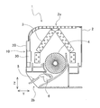
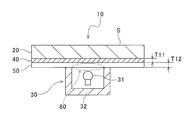
- FIG. 1st embodiment of the present invention It is a perspective view of the indoor unit concerning a 1st embodiment of the present invention. It is a cross-sectional schematic diagram of the indoor unit shown in FIG. It is a cross-sectional schematic diagram of the display device of the indoor unit shown in FIG. It is a cross-sectional schematic diagram of the display apparatus which concerns on 2nd Embodiment of this invention. It is a cross-sectional schematic diagram of the display apparatus which concerns on 3rd Embodiment of this invention.
- the indoor unit 1 As shown in FIG. 1, the indoor unit 1 according to the present embodiment is installed on an indoor wall surface or the like, and performs a cooling / heating operation or a dehumidifying operation in accordance with various commands transmitted from a remote controller (not shown). . As shown in FIG. 2, the indoor unit 1 mainly includes a casing 2, an indoor heat exchanger 3 and a fan 4 disposed in the casing 2, and a front panel 20 attached to the front surface of the casing 2. ing. A suction port 2a is provided in the upper part of the casing 2, and a blower outlet 2b is provided in the lower part.
- the indoor air sucked from the suction port 2a when the fan 4 is driven is heat-exchanged by passing through the indoor heat exchanger 3, and is blown out into the room through the air outlet 2b.
- the upper and lower flaps 5 and the left and right flaps 6 are arranged in order from the side closer to the blower outlet 2b.
- the indoor unit 1 of the present embodiment is provided with a display device 10 capable of displaying predetermined characters, symbols, and the like when a light source emits light.
- the display device 10 mainly includes the front panel 20 described above, a light emitting device 30 arranged on the back side of the front panel 20, and a design surface S that projects light emitted from the white light source 31 of the light emitting device 30. I have.
- a white LED Light Emitting Diode
- the light emitting device 30 of the present embodiment includes a plurality of white light sources 31, a substrate (not shown) that performs light emission control of the white light sources 31, and light emitted from the white light sources 31. And a reflecting plate 32 oriented toward the front panel 20 side.
- the front panel 20 is a transparent color
- a light-shielding layer 40 is formed on the back surface thereof.
- the light-shielding layer 40 has a metallic color by containing at least one of aluminum powder, pearl, and mica.
- the light shielding layer 40 is formed to have a thickness T11 of 2 ⁇ m to 20 ⁇ m so that a part of the light emitted from the white light source 31 is transmitted.
- the light shielding layer 40 is formed by metallic coating or metallic printing.
- a diffusion layer 50 that diffuses light incident on the light shielding layer 40 from the white light source 31 is disposed between the white light source 31 and the light shielding layer 40.
- the diffusion layer 50 is formed on the back surface of the light-shielding layer 40 by white or light color painting or printing.
- the diffusion layer 50 has a thickness T12 of 10 ⁇ m to 25 ⁇ m so that the light emitting portion 60 is so bright that the position of the light emitting portion of the white light source 31 cannot be specified so that almost the entire light emitting portion 60 emits light. It is formed as follows.
- the diffusion layer 50, the light-shielding layer 40, and the front panel 20 are arranged in this order from the light emitting device 30 side, and the light emitted from the white light source 31 is transmitted through the diffusion layer 50. After spreading over substantially the entire area, a part of the light is transmitted through the light-shielding layer 40, so that a metallic light-emitting display is displayed on the design surface S of the front panel 20.
- the indoor unit 1 (display device 10) of the present embodiment has the following characteristics.
- a part of the light from the white light source 31 can be transmitted through the light-shielding layer 40 exhibiting a metallic color, so that the design surface S of the front panel 20 has a unique high-quality metallic color. It is possible to express feeling and depth.
- the indoor unit 1 of the present embodiment light is transmitted through the light-shielding layer 40 formed by a technique (metallic color coating or metallic color printing) different from a half mirror formed by a technique such as vapor deposition. Can be made.
- light can be transmitted to the light-shielding layer 40 having a metallic color by including at least one of aluminum powder, pearl, and mica.
- the indoor unit 1 of the present embodiment by setting the light shielding layer 40 to a thickness of 2 ⁇ m to 20 ⁇ m, it is possible to transmit light to the light shielding layer 40.
- the light emitting portion of the white light source 31 can be blurred to make it visible as if substantially the entire light emitting unit 60 is emitting light.
- the light-emitting portion of the white light source 31 is blurred by the diffusion layer 50 that can be easily formed by coating or printing, so that the substantially entire light-emitting unit 60 emits light. It can be visually recognized.
- the diffusion layer 50 by setting the diffusion layer 50 to a thickness of 10 ⁇ m to 25 ⁇ m, it is possible to make the light emitting portion of the white light source 31 blur and make it visible as almost the entire light emitting unit 60 emits light. .
- the light blocking layer 40 is stacked on the surface of the front panel 20 on the white light source 31 side, so that the light blocking layer 40 is disposed at a position close to the white light source 31.
- the light emission display such as characters and symbols displayed on the surface S becomes clear.
- white light transmitted through the light-shielding layer 40 on the design surface S can be expressed by using the white light source 31 as a light source.
- the display device 110 mainly includes a front panel 120 attached to the front surface of the casing 2 and a light emitting device 30 disposed on the back side of the front panel 120.
- the front panel 120 is a transparent color
- a light-shielding layer 140 is formed on the front surface thereof by painting with metallic color or printing with metallic color.
- the light shielding layer 140 has a metallic color by containing at least one of aluminum powder, pearl, and mica.
- the light-shielding layer 140 is formed to have a thickness T21 of 2 ⁇ m to 20 ⁇ m so that a part of the light emitted from the white light source 31 is transmitted.
- a diffusion layer 150 that diffuses light incident on the light-shielding layer 140 from the white light source 31 is disposed between the white light source 31 and the light-shielding layer 140.
- the diffusion layer 150 is formed on the back surface of the front panel 120 by white or light color painting or printing.
- the diffusion layer 150 is formed to have a thickness T22 of 10 ⁇ m to 25 ⁇ m in order to make the light emitting portion of the white light source 31 blur and make it visible so that substantially the entire light emitting unit 160 emits light. .
- the display device 210 of this embodiment mainly includes a front panel 220 attached to the front surface of the casing 2 and a light emitting device 30 disposed on the back side of the front panel 220.
- a light-shielding layer 240 is formed on the front surface of the diffusion layer 250 by metallic paint or metallic printing.
- the light-shielding layer 240 has a metallic color by containing at least one of aluminum powder, pearl, and mica.
- the light shielding layer 240 is formed to have a thickness T31 of 2 ⁇ m to 20 ⁇ m so that a part of the light emitted from the white light source 31 is transmitted.
- the front panel 220, the diffusion layer 250, and the light-shielding layer 240 are arranged in this order from the light emitting device 30 side, and the light emitted from the white light source 31 is a transparent front surface. After passing through the panel 220 and spreading substantially over the entire area with the diffusion layer 250, a part of the light passes through the light shielding layer 240, so that a metallic light emitting display is formed on the design surface S of the light shielding layer 240. Projected.
- the diffusion layer is formed by white or light color painting or printing.
- the present invention is not limited to this, and the diffusion layer may be replaced with a white or light color sheet material.
- the sheet material is preferably a thin material that is colored lightly.
- various diffusing members can be employed as long as the light emitted from the light source can be diffused even if it is not white or light color painting or printing, or white or light color sheet material.
- a novel display device capable of transmitting light to the light-shielding layer and an air conditioner (indoor unit) including the display device can be obtained.
Landscapes
- Engineering & Computer Science (AREA)
- Chemical & Material Sciences (AREA)
- Combustion & Propulsion (AREA)
- Mechanical Engineering (AREA)
- General Engineering & Computer Science (AREA)
- Human Computer Interaction (AREA)
- Illuminated Signs And Luminous Advertising (AREA)
- Air Filters, Heat-Exchange Apparatuses, And Housings Of Air-Conditioning Units (AREA)
Abstract
遮光性の層に対して光を透過させることが可能な新規な表示装置を備えた室内機を得る。 この室内機は、ケーシングの前面に取り付けられる前面パネル20の意匠面Sに発光表示を映し出す表示装置10を備えている。この表示装置10は、光源31と、光源31から照射された光を映し出す意匠面Sと、光源31と意匠面Sとの間に配置されるメタリック色の遮光性の層40と、LED31から遮光性の層40に入射する光を拡散する拡散層50とを備えている。そして、光源31から照射された光は、拡散層50で略全領域に広がった後、その一部が遮光性の層40を透過することによって、前面パネル20の意匠面Sに映し出される。
Description
本発明は、意匠面に光源からの光を発光表示させる表示装置及びその表示装置を備えた空気調和機に関する。
近年、空気調和機など様々な機器の美観を向上させるために、筐体の内部に設けられた光源からの光を、その筐体の前面に取り付けられる前面パネルの意匠面に映し出す空気調和機が種々開発されている(例えば、特許文献1参照)。
しかしながら、光源の光を前面パネルの意匠面に映し出すには、光の透過性の高い透明色や白色等の淡色の前面パネルを採用しなければならず、暗色が必要な場合は透明基材自体が着色されたスモーク色である必要があり、前面パネルの色彩の選択が制限されていた。このため、メタリック系色等の遮光性の高い前面パネルを利用した場合、光源からの光をその前面パネルの意匠面に映し出せなかった。
そこで、この発明は、上記のような課題を解決するためになされたものであり、遮光性の層に対して光を透過させることが可能な新規な表示装置及びその表示装置を備えた空気調和機を提供することを目的とする。
第1の発明にかかる表示装置は、意匠面の裏側に配置される光源と、光源と意匠面との間に配置される遮光性の層とを備え、光源から照射された光の一部は、遮光性の層を透過して意匠面に映し出される。
このように構成すれば、遮光性の層に対して光を透過させることが可能な新規な表示装置を得ることができる。
第2の発明にかかる表示装置は、第1の発明にかかる表示装置において、遮光性の層は、メタリック色の塗装又はメタリック色の印刷によって形成される。
この表示装置では、蒸着等の手法により形成されるハーフミラー等とは異なる手法で形成される遮光性の層に対して光を透過させることができる。
第3の発明にかかる表示装置は、第2の発明にかかる表示装置において、遮光性の層は、金属粉、パール及びマイカの少なくとも1種を含む。
この表示装置では、金属粉、パール及びマイカの少なくとも1種によってメタリック色に呈した遮光性の層に対して光を透過させることができる。
第4の発明にかかる表示装置は、第1~第3のいずれかの発明にかかる表示装置において、遮光性の層は、2μm~20μmの厚みを有する。
このように構成すれば、遮光性の層に対して光を透過させることが可能となる。
第5の発明にかかる表示装置は、第1~第4のいずれかの発明にかかる表示装置において、光源と遮光性の層との間に配置され、光源から遮光性の層に入射する光を拡散する拡散層をさらに備える。
この表示装置では、光源の発光部分をぼやかして発光部の略全体が発光しているように視認させることができる。
第6の発明にかかる表示装置は、第5の発明にかかる表示装置において、拡散層は、白色又は淡色である。
この表示装置では、光源の明るさを保ちつつ、拡散層が光源の発光部分をぼやかして発光部の略全体が発光しているように視認させることができる。
第7の発明にかかる表示装置は、第5又は第6の発明にかかる表示装置において、拡散層は、塗膜層、印刷層又はシート材である。
この表示装置では、簡単に形成することができる拡散層によって、光源の発光部分をぼやかして発光部の略全体が発光しているように視認させることができる。
第8の発明にかかる表示装置は、第5~第7のいずれかの発明にかかる表示装置において、拡散層は、10μm~25μmの厚みを有する。
このように構成すれば、拡散層が光源の発光部分をぼやかして発光部の略全体が発光しているように視認させることができる。
第9の発明にかかる表示装置は、第1~第8のいずれかの発明にかかる表示装置において、遮光性の層を積層するための透明色の基材をさらに備え、遮光性の層は、基材の光源側の面に積層される。
この表示装置では、遮光性の層を光源に近い位置に配置することで、意匠面に表示される発光表示が明瞭になる。
第10の発明にかかる表示装置は、第1~第9のいずれかの発明にかかる表示装置において、光源が白色光である。
この表示装置では、意匠面に遮光性の層を透過した白色光を表現することができる。
第11の発明にかかる空気調和機は、上記したいずれかの表示装置と、筐体の前面に取り付けられる前面パネルとを備え、表示装置は、前面パネルに設けられる。
このように構成すれば、前面パネルに遮光性の層を透過した光を映し出す新規な空気調和機を得ることができる。
以上の説明に述べたように、本発明によれば、以下の効果が得られる。
第1の発明では、遮光性の層に対して光を透過させることが可能な新規な表示装置を得ることができる。
また、第2の発明では、蒸着等の手法により形成されるハーフミラー等とは異なる手法で形成される遮光性の層に対して光を透過させることができる。
また、第3の発明では、金属粉、パール及びマイカの少なくとも1種によってメタリック色に呈した遮光性の層に対して光を透過させることができる。
また、第4の発明では、遮光性の層に対して光を透過させることが可能となる。
また、第5の発明では、光源の発光部分をぼやかして発光部の略全体が発光しているように視認させることができる。
また、第6の発明では、光源の明るさを保ちつつ、拡散層が光源の発光部分をぼやかして発光部の略全体が発光しているように視認させることができる。
また、第7の発明では、簡単に形成することができる拡散層によって、光源の発光部分をぼやかして拡散層の略全体が発光しているように視認させることができる。
また、第8の発明では、拡散層が光源の発光部分をぼやかして発光部の略全体が発光しているように視認させることができる。
また、第9の発明では、遮光性の層を光源に近い位置に配置することで、意匠面に表示される発光表示が明瞭になる。
また、第10の発明では、意匠面に遮光性の層を透過した白色光を表現することができる。
また、第11の発明では、前面パネルに遮光性の層を透過した光を映し出す新規な空気調和機を得ることができる。
以下、図面に基づいて、本発明に係る空気調和機の室内機の実施形態について説明する。
(第1実施形態)
[室内機の全体構成]
本実施形態の室内機1は、図1に示すように、室内の壁面等に設置され、リモコン(図示せず)から送信される各種指令に応じて、冷房・暖房運転や除湿運転などを行う。この室内機1は、図2に示すように、主として、ケーシング2と、そのケーシング2内に配置される室内熱交換器3及びファン4と、ケーシング2の前面に取り付けられる前面パネル20とを備えている。このケーシング2の上部には吸込口2aが設けられると共に、下部には吹出口2bが設けられている。ファン4が駆動することによって吸込口2aから吸い込まれた室内空気は、室内熱交換器3を通過することによって熱交換されて、吹出口2bを介して室内に吹き出される。また、ファン4から吹出口2bに至る流路上には、吹出口2bに近い方から順に、上下フラップ5,左右フラップ6が配置されている。
[室内機の全体構成]
本実施形態の室内機1は、図1に示すように、室内の壁面等に設置され、リモコン(図示せず)から送信される各種指令に応じて、冷房・暖房運転や除湿運転などを行う。この室内機1は、図2に示すように、主として、ケーシング2と、そのケーシング2内に配置される室内熱交換器3及びファン4と、ケーシング2の前面に取り付けられる前面パネル20とを備えている。このケーシング2の上部には吸込口2aが設けられると共に、下部には吹出口2bが設けられている。ファン4が駆動することによって吸込口2aから吸い込まれた室内空気は、室内熱交換器3を通過することによって熱交換されて、吹出口2bを介して室内に吹き出される。また、ファン4から吹出口2bに至る流路上には、吹出口2bに近い方から順に、上下フラップ5,左右フラップ6が配置されている。
[表示装置]
本実施形態の室内機1には、光源が発光して所定の文字や記号等を表示することが可能な表示装置10が設けられている。この表示装置10は、主として、上記した前面パネル20と、その前面パネル20の背面側に配置される発光装置30と、発光装置30の白色光源31から照射された光を映し出す意匠面Sとを備えている。なお、上記した白色光源31の一例として、白色LED(Light Emitting Diode)等を用いることができる。
本実施形態の室内機1には、光源が発光して所定の文字や記号等を表示することが可能な表示装置10が設けられている。この表示装置10は、主として、上記した前面パネル20と、その前面パネル20の背面側に配置される発光装置30と、発光装置30の白色光源31から照射された光を映し出す意匠面Sとを備えている。なお、上記した白色光源31の一例として、白色LED(Light Emitting Diode)等を用いることができる。
本実施形態の発光装置30は、図3に示すように、複数の白色光源31と、当該白色光源31の発光制御を行う基板(図示せず)と、当該白色光源31から照射された光を前面パネル20側に指向させる反射板32とを備えている。
ここで、本実施形態では、前面パネル20は、透明色であって、その背面には遮光性の層40が形成されている。この遮光性の層40は、アルミ粉、パール及びマイカの少なくとも1種を含むことによって、メタリック色を呈している。そして、遮光性の層40は、白色光源31から照射された光の一部が透過するように、その厚さT11が2μm~20μmとなるように形成されている。この遮光性の層40は、蒸着やスパッタなどの手法で形成されるハーフミラーとは異なり、メタリック色の塗装又はメタリック色の印刷によって形成されている。
また、本実施形態では、白色光源31と遮光性の層40との間には、白色光源31から遮光性の層40に入射する光を拡散する拡散層50が配置されている。この拡散層50は、白色又は淡色の塗装又は印刷によって、上記した遮光性の層40の背面に形成されている。そして、拡散層50は、白色光源31の発光部分の位置を特定できない程にぼやかして発光部60の略全体が発光しているように視認させるために、その厚さT12が10μm~25μmとなるように形成されている。
本実施形態では、上記したように、発光装置30側から、拡散層50、遮光性の層40、前面パネル20の順に配置されており、白色光源31から照射された光は、拡散層50で略全領域に広がった後、その一部が遮光性の層40を透過することによって、前面パネル20の意匠面Sにメタリック色の発光表示が映し出される。
[本実施形態の室内機の特徴]
本実施形態の室内機1(表示装置10)には、以下のような特徴がある。
本実施形態の室内機1(表示装置10)には、以下のような特徴がある。
本実施形態の室内機1では、白色光源31からの光の一部を、メタリック色を呈する遮光性の層40に透過させることができるので、前面パネル20の意匠面Sにメタリック色独特の高級感や深みを表現することが可能となる。
本実施形態の室内機1では、蒸着等の手法により形成されるハーフミラー等とは異なる手法(メタリック色の塗装又はメタリック色の印刷)で形成される遮光性の層40に対して光を透過させることができる。
本実施形態の室内機1では、アルミ粉、パール及びマイカの少なくとも1種が含まれることによりメタリック色に呈した遮光性の層40に対して、光を透過させることができる。
本実施形態の室内機1では、遮光性の層40を2μm~20μmの厚みにすることによって、当該遮光性の層40に対して光を透過させることが可能となる。
本実施形態の室内機1では、拡散層50を設けることによって、白色光源31の発光部分をぼやかして発光部60の略全体が発光しているように視認させることができる。
本実施形態の室内機1では、拡散層50を白色又は淡色にすることによって、白色光源31の明るさを保ちつつ、拡散層50が白色光源31の発光部分をぼやかして発光部60の略全体が発光しているように視認させることができる。
本実施形態の室内機1では、拡散層50を、塗膜又は印刷によって簡単に形成することができる拡散層50によって、白色光源31の発光部分をぼやかして発光部60の略全体が発光しているように視認させることができる。
本実施形態の室内機1では、拡散層50を10μm~25μmの厚みにすることによって、白色光源31の発光部分をぼやかして発光部60の略全体が発光しているように視認させることができる。
本実施形態の室内機1では、遮光性の層40を前面パネル20の白色光源31側の面に積層することで、遮光性の層40を白色光源31に近い位置に配置されるので、意匠面Sに表示される文字や記号などの発光表示が明瞭になる。
本実施形態の室内機1では、光源として白色の白色光源31を用いることによって、意匠面Sに遮光性の層40を透過した白色光を表現することができる。
(第2実施形態)
上記した第1実施形態では、透明色の前面パネル20の背面に遮光性の層40を形成する例について説明したが、この第2実施形態では、前面パネル20の前面に遮光性の層を形成している。以下、図4を参照して、第2実施形態に係る表示装置110を詳細に説明する。なお、第1実施形態の表示装置と同一の構成については、同一番号を付し、その説明を省略する。
上記した第1実施形態では、透明色の前面パネル20の背面に遮光性の層40を形成する例について説明したが、この第2実施形態では、前面パネル20の前面に遮光性の層を形成している。以下、図4を参照して、第2実施形態に係る表示装置110を詳細に説明する。なお、第1実施形態の表示装置と同一の構成については、同一番号を付し、その説明を省略する。
[表示装置]
本実施形態の表示装置110は、主として、ケーシング2の前面に取り付けられる前面パネル120と、その前面パネル120の背面側に配置される発光装置30とを備えている。
本実施形態の表示装置110は、主として、ケーシング2の前面に取り付けられる前面パネル120と、その前面パネル120の背面側に配置される発光装置30とを備えている。
この第2実施形態では、前面パネル120は、透明色であって、その前面にはメタリック色の塗装又はメタリック色の印刷によって遮光性の層140が形成されている。この遮光性の層140は、アルミ粉、パール及びマイカの少なくとも1種を含むことによって、メタリック色を呈している。そして、遮光性の層140は、白色光源31から照射された光の一部が透過するように、その厚さT21が2μm~20μmとなるように形成されている。
また、本実施形態では、白色光源31と遮光性の層140との間には、白色光源31から遮光性の層140に入射する光を拡散する拡散層150が配置されている。この拡散層150は、白色又は淡色の塗装又は印刷によって、前面パネル120の背面に形成されている。そして、拡散層150は、白色光源31の発光部分をぼやかして発光部160の略全体が発光しているように視認させるために、その厚さT22が10μm~25μmとなるように形成されている。
本実施形態では、上記したように、発光装置30側から、拡散層150、前面パネル120、遮光性の層140の順に配置されており、白色光源31から照射された光は、拡散層150で略全領域に広がった後、透明色の前面パネル120を介して、その一部が遮光性の層140を透過することによって、遮光性の層140の意匠面Sにメタリック色の発光表示が映し出される。
(第3実施形態)
上記した第1及び第2実施形態では、透明色の前面パネル20,120の背面に拡散層50,150を形成する例について説明したが、この第3実施形態では、前面パネル20の前面に拡散層を形成している。以下、図5を参照して、第3実施形態に係る表示装置210を詳細に説明する。なお、第1実施形態の表示装置と同一の構成については、同一番号を付し、その説明を省略する。
上記した第1及び第2実施形態では、透明色の前面パネル20,120の背面に拡散層50,150を形成する例について説明したが、この第3実施形態では、前面パネル20の前面に拡散層を形成している。以下、図5を参照して、第3実施形態に係る表示装置210を詳細に説明する。なお、第1実施形態の表示装置と同一の構成については、同一番号を付し、その説明を省略する。
[表示装置]
本実施形態の表示装置210は、主として、ケーシング2の前面に取り付けられる前面パネル220と、その前面パネル220の背面側に配置される発光装置30とを備えている。
本実施形態の表示装置210は、主として、ケーシング2の前面に取り付けられる前面パネル220と、その前面パネル220の背面側に配置される発光装置30とを備えている。
この第3実施形態では、前面パネル220は、透明色であって、その前面には白色光源31から後述する遮光性の層240に入射する光を拡散する拡散層250が配置されている。この拡散層250は、白色又は淡色の塗装又は印刷によって形成されている。そして、拡散層250は、白色光源31の発光部分をぼやかして発光部260の略全体が発光しているように視認させるために、その厚さT32が10μm~25μmとなるように形成されている。
また、拡散層250の前面にはメタリック色の塗装又はメタリック色の印刷によって遮光性の層240が形成されている。この遮光性の層240は、アルミ粉、パール及びマイカの少なくとも1種を含むことによって、メタリック色を呈している。そして、遮光性の層240は、白色光源31から照射された光の一部が透過するように、その厚さT31が2μm~20μmとなるように形成されている。
本実施形態では、上記したように、発光装置30側から、前面パネル220、拡散層250、遮光性の層240の順に配置されており、白色光源31から照射された光は、透明色の前面パネル220を通過して、拡散層250で略全領域に広がった後、その一部が遮光性の層240を透過することによって、遮光性の層240の意匠面Sにメタリック色の発光表示が映し出される。
以上、本発明の実施形態について図面に基づいて説明したが、具体的な構成は、これらの実施形態に限定されるものでないと考えられるべきである。本発明の範囲は、上記した実施形態の説明だけではなく特許請求の範囲によって示され、さらに特許請求の範囲と均等の意味および範囲内でのすべての変更が含まれる。
例えば、上記実施形態では、拡散層を白色又は淡色の塗装又は印刷によって形成する例について説明したが、本発明はこれに限らず、当該拡散層を白色又は淡色のシート材で代用しても良い。なお、拡散層としてシート材を用いた場合、当該シート材は淡色系に着色された薄手のものであることが好ましい。
また、白色又は淡色の塗装若しくは印刷、又は、白色又は淡色のシート材でなくても、光源から照射される光を拡散可能であれば、種々の拡散部材を採用することができる。
また、上記実施形態では、遮光性の層がアルミ粉を含む例について説明したが、本発明はこれに限らず、遮光性の層がメタリック色を呈するようにアルミ粉以外の金属粉を用いてもよい。
また、上記実施形態では、遮光性の層にアルミ粉、パール及びマイカの少なくとも一種を含ませる例について説明したが、本発明はこれに限らず、遮光性の層にアルミ粉、パール及びマイカ以外の光輝材を含ませてもよい。
本発明を利用すれば、遮光性の層に対して光を透過させることが可能な新規な表示装置及びその表示装置を備えた空気調和機(室内機)を得ることができる。
1 室内機(空気調和機)
10,110,210 表示装置
20,120,220 前面パネル(基材)
30 発光装置
31 白色光源(LED)
40,140,240 遮光性の層
50,150,250 拡散層
10,110,210 表示装置
20,120,220 前面パネル(基材)
30 発光装置
31 白色光源(LED)
40,140,240 遮光性の層
50,150,250 拡散層
Claims (11)
- 意匠面の裏側に配置される光源と、
前記光源と前記意匠面との間に配置される遮光性の層とを備え、
前記光源から照射された光の一部は、前記遮光性の層を透過して前記意匠面に映し出されることを特徴とする、表示装置。 - 前記遮光性の層は、メタリック色の塗装又はメタリック色の印刷によって形成されることを特徴とする、請求項1に記載の表示装置。
- 前記遮光性の層は、金属粉、パール及びマイカの少なくとも1種を含むことを特徴とする、請求項2に記載の表示装置。
- 前記遮光性の層は、2μm~20μmの厚みを有することを特徴とする、請求項1~3のいずれか1項に記載の表示装置。
- 前記光源と前記遮光性の層との間に配置され、前記光源から前記遮光性の層に入射する光を拡散する拡散層をさらに備えることを特徴とする、請求項1~4のいずれか1項に記載の表示装置。
- 前記拡散層は、白色又は淡色であることを特徴とする、請求項5に記載の表示装置。
- 前記拡散層は、塗膜層、印刷層又はシート材であることを特徴とする、請求項5又は6に記載の表示装置。
- 前記拡散層は、10μm~25μmの厚みを有することを特徴とする、請求項5~7のいずれか1項に記載の表示装置。
- 前記遮光性の層を積層するための透明色の基材をさらに備え、
前記遮光性の層は、前記基材の前記光源側の面に積層されることを特徴とする、請求項1~8のいずれか1項に記載の表示装置。 - 前記光源が白色光であることを特徴とする、請求項1~9のいずれか1項に記載の表示装置。
- 請求項1~10のいずれか1項に記載の表示装置と、
筐体の前面に取り付けられる前面パネルとを備え、
前記表示装置は、前記前面パネルに設けられることを特徴とする、空気調和機。
Priority Applications (1)
| Application Number | Priority Date | Filing Date | Title |
|---|---|---|---|
| CN2010800087503A CN102326194A (zh) | 2009-04-24 | 2010-04-19 | 显示装置以及空调机 |
Applications Claiming Priority (2)
| Application Number | Priority Date | Filing Date | Title |
|---|---|---|---|
| JP2009106181A JP2010256597A (ja) | 2009-04-24 | 2009-04-24 | 表示装置及び空気調和機 |
| JP2009-106181 | 2009-04-24 |
Publications (1)
| Publication Number | Publication Date |
|---|---|
| WO2010122987A1 true WO2010122987A1 (ja) | 2010-10-28 |
Family
ID=43011104
Family Applications (1)
| Application Number | Title | Priority Date | Filing Date |
|---|---|---|---|
| PCT/JP2010/056950 Ceased WO2010122987A1 (ja) | 2009-04-24 | 2010-04-19 | 表示装置及び空気調和機 |
Country Status (3)
| Country | Link |
|---|---|
| JP (1) | JP2010256597A (ja) |
| CN (1) | CN102326194A (ja) |
| WO (1) | WO2010122987A1 (ja) |
Cited By (1)
| Publication number | Priority date | Publication date | Assignee | Title |
|---|---|---|---|---|
| CN113883666A (zh) * | 2021-10-09 | 2022-01-04 | Tcl空调器(中山)有限公司 | 一种空调器及其色温显示方法 |
Families Citing this family (3)
| Publication number | Priority date | Publication date | Assignee | Title |
|---|---|---|---|---|
| CN103807993A (zh) * | 2012-11-14 | 2014-05-21 | 珠海格力电器股份有限公司 | 空调器图案显示结构及包括该结构的空调器 |
| JPWO2018016065A1 (ja) * | 2016-07-22 | 2019-02-21 | 三菱電機株式会社 | 空気調和機の室内機 |
| CN109916063B (zh) * | 2019-03-04 | 2021-07-13 | 上海美控智慧建筑有限公司 | 面板组件、线控器、空调器及面板组件的加工方法 |
Citations (5)
| Publication number | Priority date | Publication date | Assignee | Title |
|---|---|---|---|---|
| JPS6141294U (ja) * | 1985-05-16 | 1986-03-15 | マルイ工業株式会社 | 表示装置 |
| JPH01205193A (ja) * | 1988-02-12 | 1989-08-17 | Koito Mfg Co Ltd | 表示装置 |
| JPH055600U (ja) * | 1991-07-12 | 1993-01-26 | 株式会社ヨンマルゴ | 自動車用ガーニツシユ |
| JP2002013791A (ja) * | 2000-06-29 | 2002-01-18 | Daikin Ind Ltd | 空気調和機 |
| JP2004038068A (ja) * | 2002-07-08 | 2004-02-05 | Shin Etsu Polymer Co Ltd | 表示体用部材、表示体用部材を使用した表示体及び押釦スイッチ構造体 |
Family Cites Families (3)
| Publication number | Priority date | Publication date | Assignee | Title |
|---|---|---|---|---|
| JP4627648B2 (ja) * | 2004-09-27 | 2011-02-09 | 日立アプライアンス株式会社 | 表示装置及びこの表示装置を用いた空気調和機 |
| JP2006267218A (ja) * | 2005-03-22 | 2006-10-05 | Three M Innovative Properties Co | 立体的メタリックイメージ表示体および表示システム |
| JP5127614B2 (ja) * | 2007-10-03 | 2013-01-23 | 三菱電機株式会社 | 空気調和機の室内機 |
-
2009
- 2009-04-24 JP JP2009106181A patent/JP2010256597A/ja active Pending
-
2010
- 2010-04-19 WO PCT/JP2010/056950 patent/WO2010122987A1/ja not_active Ceased
- 2010-04-19 CN CN2010800087503A patent/CN102326194A/zh active Pending
Patent Citations (5)
| Publication number | Priority date | Publication date | Assignee | Title |
|---|---|---|---|---|
| JPS6141294U (ja) * | 1985-05-16 | 1986-03-15 | マルイ工業株式会社 | 表示装置 |
| JPH01205193A (ja) * | 1988-02-12 | 1989-08-17 | Koito Mfg Co Ltd | 表示装置 |
| JPH055600U (ja) * | 1991-07-12 | 1993-01-26 | 株式会社ヨンマルゴ | 自動車用ガーニツシユ |
| JP2002013791A (ja) * | 2000-06-29 | 2002-01-18 | Daikin Ind Ltd | 空気調和機 |
| JP2004038068A (ja) * | 2002-07-08 | 2004-02-05 | Shin Etsu Polymer Co Ltd | 表示体用部材、表示体用部材を使用した表示体及び押釦スイッチ構造体 |
Cited By (2)
| Publication number | Priority date | Publication date | Assignee | Title |
|---|---|---|---|---|
| CN113883666A (zh) * | 2021-10-09 | 2022-01-04 | Tcl空调器(中山)有限公司 | 一种空调器及其色温显示方法 |
| CN113883666B (zh) * | 2021-10-09 | 2023-03-10 | Tcl空调器(中山)有限公司 | 一种空调器及其色温显示方法 |
Also Published As
| Publication number | Publication date |
|---|---|
| JP2010256597A (ja) | 2010-11-11 |
| CN102326194A (zh) | 2012-01-18 |
Similar Documents
| Publication | Publication Date | Title |
|---|---|---|
| US7347608B2 (en) | Window element | |
| JP6350489B2 (ja) | 表示装置 | |
| JP6676409B2 (ja) | コーティングされたガラスまたはガラスセラミック製品 | |
| JP2009103427A5 (ja) | ||
| CN100538781C (zh) | 显示装置及使用该显示装置的空调机 | |
| CN104396346B (zh) | 透明无机薄膜电致发光显示器元件及其制造方法 | |
| JP4145106B2 (ja) | 空気調和機 | |
| JP2010256597A (ja) | 表示装置及び空気調和機 | |
| WO2015149487A1 (zh) | 透明显示设备 | |
| KR101558421B1 (ko) | Led 채널간판 | |
| JP4045147B2 (ja) | 空気調和機 | |
| JP2018163343A (ja) | 加飾シート、表示装置、照明装置、窓 | |
| JP2009243737A (ja) | 空気調和機 | |
| CN101545655A (zh) | 空调机 | |
| WO2013011819A1 (ja) | 照明装置 | |
| JP6430291B2 (ja) | 照明装置 | |
| CN105333459A (zh) | 灶具的操作装置及灶具 | |
| JP7510613B2 (ja) | 加飾シート付き表示装置用積層体および加飾シート付き表示装置 | |
| JP2018163344A (ja) | 加飾シート、表示装置、照明装置、窓 | |
| KR20080044826A (ko) | 다중 반사 패널 | |
| JP2019029201A (ja) | 導光板及び面光源装置 | |
| KR101757864B1 (ko) | 광고용 입체 다면발광 채널 | |
| JP2011164648A (ja) | 表示装置及び空気調和機 | |
| WO2011026432A1 (zh) | 挂壁式空调器室内机及其发光板 | |
| JP2012018218A (ja) | 表示装置 |
Legal Events
| Date | Code | Title | Description |
|---|---|---|---|
| WWE | Wipo information: entry into national phase |
Ref document number: 201080008750.3 Country of ref document: CN |
|
| 121 | Ep: the epo has been informed by wipo that ep was designated in this application |
Ref document number: 10767044 Country of ref document: EP Kind code of ref document: A1 |
|
| NENP | Non-entry into the national phase |
Ref country code: DE |
|
| 122 | Ep: pct application non-entry in european phase |
Ref document number: 10767044 Country of ref document: EP Kind code of ref document: A1 |