WO2010114039A1 - 固体電解質型燃料電池 - Google Patents
固体電解質型燃料電池 Download PDFInfo
- Publication number
- WO2010114039A1 WO2010114039A1 PCT/JP2010/055906 JP2010055906W WO2010114039A1 WO 2010114039 A1 WO2010114039 A1 WO 2010114039A1 JP 2010055906 W JP2010055906 W JP 2010055906W WO 2010114039 A1 WO2010114039 A1 WO 2010114039A1
- Authority
- WO
- WIPO (PCT)
- Prior art keywords
- temperature
- pox
- reforming
- fuel cell
- restart
- Prior art date
- Legal status (The legal status is an assumption and is not a legal conclusion. Google has not performed a legal analysis and makes no representation as to the accuracy of the status listed.)
- Ceased
Links
Images


Classifications
-
- H—ELECTRICITY
- H01—ELECTRIC ELEMENTS
- H01M—PROCESSES OR MEANS, e.g. BATTERIES, FOR THE DIRECT CONVERSION OF CHEMICAL ENERGY INTO ELECTRICAL ENERGY
- H01M8/00—Fuel cells; Manufacture thereof
- H01M8/04—Auxiliary arrangements, e.g. for control of pressure or for circulation of fluids
- H01M8/04298—Processes for controlling fuel cells or fuel cell systems
- H01M8/04313—Processes for controlling fuel cells or fuel cell systems characterised by the detection or assessment of variables; characterised by the detection or assessment of failure or abnormal function
- H01M8/0432—Temperature; Ambient temperature
- H01M8/04373—Temperature; Ambient temperature of auxiliary devices, e.g. reformers, compressors, burners
-
- C—CHEMISTRY; METALLURGY
- C01—INORGANIC CHEMISTRY
- C01B—NON-METALLIC ELEMENTS; COMPOUNDS THEREOF; METALLOIDS OR COMPOUNDS THEREOF NOT COVERED BY SUBCLASS C01C
- C01B3/00—Hydrogen; Gaseous mixtures containing hydrogen; Separation of hydrogen from mixtures containing it; Purification of hydrogen
- C01B3/02—Production of hydrogen or of gaseous mixtures containing a substantial proportion of hydrogen
- C01B3/32—Production of hydrogen or of gaseous mixtures containing a substantial proportion of hydrogen by reaction of gaseous or liquid organic compounds with gasifying agents, e.g. water, carbon dioxide, air
- C01B3/34—Production of hydrogen or of gaseous mixtures containing a substantial proportion of hydrogen by reaction of gaseous or liquid organic compounds with gasifying agents, e.g. water, carbon dioxide, air by reaction of hydrocarbons with gasifying agents
- C01B3/38—Production of hydrogen or of gaseous mixtures containing a substantial proportion of hydrogen by reaction of gaseous or liquid organic compounds with gasifying agents, e.g. water, carbon dioxide, air by reaction of hydrocarbons with gasifying agents using catalysts
- C01B3/382—Multi-step processes
-
- C—CHEMISTRY; METALLURGY
- C01—INORGANIC CHEMISTRY
- C01B—NON-METALLIC ELEMENTS; COMPOUNDS THEREOF; METALLOIDS OR COMPOUNDS THEREOF NOT COVERED BY SUBCLASS C01C
- C01B3/00—Hydrogen; Gaseous mixtures containing hydrogen; Separation of hydrogen from mixtures containing it; Purification of hydrogen
- C01B3/02—Production of hydrogen or of gaseous mixtures containing a substantial proportion of hydrogen
- C01B3/32—Production of hydrogen or of gaseous mixtures containing a substantial proportion of hydrogen by reaction of gaseous or liquid organic compounds with gasifying agents, e.g. water, carbon dioxide, air
- C01B3/34—Production of hydrogen or of gaseous mixtures containing a substantial proportion of hydrogen by reaction of gaseous or liquid organic compounds with gasifying agents, e.g. water, carbon dioxide, air by reaction of hydrocarbons with gasifying agents
- C01B3/38—Production of hydrogen or of gaseous mixtures containing a substantial proportion of hydrogen by reaction of gaseous or liquid organic compounds with gasifying agents, e.g. water, carbon dioxide, air by reaction of hydrocarbons with gasifying agents using catalysts
- C01B3/384—Production of hydrogen or of gaseous mixtures containing a substantial proportion of hydrogen by reaction of gaseous or liquid organic compounds with gasifying agents, e.g. water, carbon dioxide, air by reaction of hydrocarbons with gasifying agents using catalysts the catalyst being continuously externally heated
-
- H—ELECTRICITY
- H01—ELECTRIC ELEMENTS
- H01M—PROCESSES OR MEANS, e.g. BATTERIES, FOR THE DIRECT CONVERSION OF CHEMICAL ENERGY INTO ELECTRICAL ENERGY
- H01M8/00—Fuel cells; Manufacture thereof
- H01M8/02—Details
- H01M8/0271—Sealing or supporting means around electrodes, matrices or membranes
-
- H—ELECTRICITY
- H01—ELECTRIC ELEMENTS
- H01M—PROCESSES OR MEANS, e.g. BATTERIES, FOR THE DIRECT CONVERSION OF CHEMICAL ENERGY INTO ELECTRICAL ENERGY
- H01M8/00—Fuel cells; Manufacture thereof
- H01M8/04—Auxiliary arrangements, e.g. for control of pressure or for circulation of fluids
- H01M8/04223—Auxiliary arrangements, e.g. for control of pressure or for circulation of fluids during start-up or shut-down; Depolarisation or activation, e.g. purging; Means for short-circuiting defective fuel cells
- H01M8/04225—Auxiliary arrangements, e.g. for control of pressure or for circulation of fluids during start-up or shut-down; Depolarisation or activation, e.g. purging; Means for short-circuiting defective fuel cells during start-up
-
- H—ELECTRICITY
- H01—ELECTRIC ELEMENTS
- H01M—PROCESSES OR MEANS, e.g. BATTERIES, FOR THE DIRECT CONVERSION OF CHEMICAL ENERGY INTO ELECTRICAL ENERGY
- H01M8/00—Fuel cells; Manufacture thereof
- H01M8/04—Auxiliary arrangements, e.g. for control of pressure or for circulation of fluids
- H01M8/04223—Auxiliary arrangements, e.g. for control of pressure or for circulation of fluids during start-up or shut-down; Depolarisation or activation, e.g. purging; Means for short-circuiting defective fuel cells
- H01M8/04228—Auxiliary arrangements, e.g. for control of pressure or for circulation of fluids during start-up or shut-down; Depolarisation or activation, e.g. purging; Means for short-circuiting defective fuel cells during shut-down
-
- H—ELECTRICITY
- H01—ELECTRIC ELEMENTS
- H01M—PROCESSES OR MEANS, e.g. BATTERIES, FOR THE DIRECT CONVERSION OF CHEMICAL ENERGY INTO ELECTRICAL ENERGY
- H01M8/00—Fuel cells; Manufacture thereof
- H01M8/06—Combination of fuel cells with means for production of reactants or for treatment of residues
- H01M8/0606—Combination of fuel cells with means for production of reactants or for treatment of residues with means for production of gaseous reactants
- H01M8/0612—Combination of fuel cells with means for production of reactants or for treatment of residues with means for production of gaseous reactants from carbon-containing material
- H01M8/0618—Reforming processes, e.g. autothermal, partial oxidation or steam reforming
-
- H—ELECTRICITY
- H01—ELECTRIC ELEMENTS
- H01M—PROCESSES OR MEANS, e.g. BATTERIES, FOR THE DIRECT CONVERSION OF CHEMICAL ENERGY INTO ELECTRICAL ENERGY
- H01M8/00—Fuel cells; Manufacture thereof
- H01M8/24—Grouping of fuel cells, e.g. stacking of fuel cells
- H01M8/241—Grouping of fuel cells, e.g. stacking of fuel cells with solid or matrix-supported electrolytes
- H01M8/2425—High-temperature cells with solid electrolytes
- H01M8/2428—Grouping by arranging unit cells on a surface of any form, e.g. planar or tubular
-
- H—ELECTRICITY
- H01—ELECTRIC ELEMENTS
- H01M—PROCESSES OR MEANS, e.g. BATTERIES, FOR THE DIRECT CONVERSION OF CHEMICAL ENERGY INTO ELECTRICAL ENERGY
- H01M8/00—Fuel cells; Manufacture thereof
- H01M8/24—Grouping of fuel cells, e.g. stacking of fuel cells
- H01M8/241—Grouping of fuel cells, e.g. stacking of fuel cells with solid or matrix-supported electrolytes
- H01M8/2425—High-temperature cells with solid electrolytes
- H01M8/243—Grouping of unit cells of tubular or cylindrical configuration
-
- H—ELECTRICITY
- H01—ELECTRIC ELEMENTS
- H01M—PROCESSES OR MEANS, e.g. BATTERIES, FOR THE DIRECT CONVERSION OF CHEMICAL ENERGY INTO ELECTRICAL ENERGY
- H01M8/00—Fuel cells; Manufacture thereof
- H01M8/24—Grouping of fuel cells, e.g. stacking of fuel cells
- H01M8/2465—Details of groupings of fuel cells
- H01M8/2484—Details of groupings of fuel cells characterised by external manifolds
-
- C—CHEMISTRY; METALLURGY
- C01—INORGANIC CHEMISTRY
- C01B—NON-METALLIC ELEMENTS; COMPOUNDS THEREOF; METALLOIDS OR COMPOUNDS THEREOF NOT COVERED BY SUBCLASS C01C
- C01B2203/00—Integrated processes for the production of hydrogen or synthesis gas
- C01B2203/02—Processes for making hydrogen or synthesis gas
- C01B2203/0205—Processes for making hydrogen or synthesis gas containing a reforming step
- C01B2203/0227—Processes for making hydrogen or synthesis gas containing a reforming step containing a catalytic reforming step
- C01B2203/0233—Processes for making hydrogen or synthesis gas containing a reforming step containing a catalytic reforming step the reforming step being a steam reforming step
-
- C—CHEMISTRY; METALLURGY
- C01—INORGANIC CHEMISTRY
- C01B—NON-METALLIC ELEMENTS; COMPOUNDS THEREOF; METALLOIDS OR COMPOUNDS THEREOF NOT COVERED BY SUBCLASS C01C
- C01B2203/00—Integrated processes for the production of hydrogen or synthesis gas
- C01B2203/02—Processes for making hydrogen or synthesis gas
- C01B2203/0205—Processes for making hydrogen or synthesis gas containing a reforming step
- C01B2203/0227—Processes for making hydrogen or synthesis gas containing a reforming step containing a catalytic reforming step
- C01B2203/0244—Processes for making hydrogen or synthesis gas containing a reforming step containing a catalytic reforming step the reforming step being an autothermal reforming step, e.g. secondary reforming processes
-
- C—CHEMISTRY; METALLURGY
- C01—INORGANIC CHEMISTRY
- C01B—NON-METALLIC ELEMENTS; COMPOUNDS THEREOF; METALLOIDS OR COMPOUNDS THEREOF NOT COVERED BY SUBCLASS C01C
- C01B2203/00—Integrated processes for the production of hydrogen or synthesis gas
- C01B2203/02—Processes for making hydrogen or synthesis gas
- C01B2203/025—Processes for making hydrogen or synthesis gas containing a partial oxidation step
- C01B2203/0261—Processes for making hydrogen or synthesis gas containing a partial oxidation step containing a catalytic partial oxidation step [CPO]
-
- C—CHEMISTRY; METALLURGY
- C01—INORGANIC CHEMISTRY
- C01B—NON-METALLIC ELEMENTS; COMPOUNDS THEREOF; METALLOIDS OR COMPOUNDS THEREOF NOT COVERED BY SUBCLASS C01C
- C01B2203/00—Integrated processes for the production of hydrogen or synthesis gas
- C01B2203/06—Integration with other chemical processes
- C01B2203/066—Integration with other chemical processes with fuel cells
-
- C—CHEMISTRY; METALLURGY
- C01—INORGANIC CHEMISTRY
- C01B—NON-METALLIC ELEMENTS; COMPOUNDS THEREOF; METALLOIDS OR COMPOUNDS THEREOF NOT COVERED BY SUBCLASS C01C
- C01B2203/00—Integrated processes for the production of hydrogen or synthesis gas
- C01B2203/08—Methods of heating or cooling
- C01B2203/0805—Methods of heating the process for making hydrogen or synthesis gas
- C01B2203/0811—Methods of heating the process for making hydrogen or synthesis gas by combustion of fuel
-
- C—CHEMISTRY; METALLURGY
- C01—INORGANIC CHEMISTRY
- C01B—NON-METALLIC ELEMENTS; COMPOUNDS THEREOF; METALLOIDS OR COMPOUNDS THEREOF NOT COVERED BY SUBCLASS C01C
- C01B2203/00—Integrated processes for the production of hydrogen or synthesis gas
- C01B2203/10—Catalysts for performing the hydrogen forming reactions
- C01B2203/1041—Composition of the catalyst
- C01B2203/1047—Group VIII metal catalysts
- C01B2203/1052—Nickel or cobalt catalysts
- C01B2203/1058—Nickel catalysts
-
- C—CHEMISTRY; METALLURGY
- C01—INORGANIC CHEMISTRY
- C01B—NON-METALLIC ELEMENTS; COMPOUNDS THEREOF; METALLOIDS OR COMPOUNDS THEREOF NOT COVERED BY SUBCLASS C01C
- C01B2203/00—Integrated processes for the production of hydrogen or synthesis gas
- C01B2203/10—Catalysts for performing the hydrogen forming reactions
- C01B2203/1041—Composition of the catalyst
- C01B2203/1047—Group VIII metal catalysts
- C01B2203/1064—Platinum group metal catalysts
-
- C—CHEMISTRY; METALLURGY
- C01—INORGANIC CHEMISTRY
- C01B—NON-METALLIC ELEMENTS; COMPOUNDS THEREOF; METALLOIDS OR COMPOUNDS THEREOF NOT COVERED BY SUBCLASS C01C
- C01B2203/00—Integrated processes for the production of hydrogen or synthesis gas
- C01B2203/12—Feeding the process for making hydrogen or synthesis gas
- C01B2203/1258—Pre-treatment of the feed
-
- C—CHEMISTRY; METALLURGY
- C01—INORGANIC CHEMISTRY
- C01B—NON-METALLIC ELEMENTS; COMPOUNDS THEREOF; METALLOIDS OR COMPOUNDS THEREOF NOT COVERED BY SUBCLASS C01C
- C01B2203/00—Integrated processes for the production of hydrogen or synthesis gas
- C01B2203/16—Controlling the process
- C01B2203/1604—Starting up the process
-
- C—CHEMISTRY; METALLURGY
- C01—INORGANIC CHEMISTRY
- C01B—NON-METALLIC ELEMENTS; COMPOUNDS THEREOF; METALLOIDS OR COMPOUNDS THEREOF NOT COVERED BY SUBCLASS C01C
- C01B2203/00—Integrated processes for the production of hydrogen or synthesis gas
- C01B2203/16—Controlling the process
- C01B2203/1609—Shutting down the process
-
- C—CHEMISTRY; METALLURGY
- C01—INORGANIC CHEMISTRY
- C01B—NON-METALLIC ELEMENTS; COMPOUNDS THEREOF; METALLOIDS OR COMPOUNDS THEREOF NOT COVERED BY SUBCLASS C01C
- C01B2203/00—Integrated processes for the production of hydrogen or synthesis gas
- C01B2203/16—Controlling the process
- C01B2203/1614—Controlling the temperature
- C01B2203/1619—Measuring the temperature
-
- C—CHEMISTRY; METALLURGY
- C01—INORGANIC CHEMISTRY
- C01B—NON-METALLIC ELEMENTS; COMPOUNDS THEREOF; METALLOIDS OR COMPOUNDS THEREOF NOT COVERED BY SUBCLASS C01C
- C01B2203/00—Integrated processes for the production of hydrogen or synthesis gas
- C01B2203/16—Controlling the process
- C01B2203/1685—Control based on demand of downstream process
-
- H—ELECTRICITY
- H01—ELECTRIC ELEMENTS
- H01M—PROCESSES OR MEANS, e.g. BATTERIES, FOR THE DIRECT CONVERSION OF CHEMICAL ENERGY INTO ELECTRICAL ENERGY
- H01M8/00—Fuel cells; Manufacture thereof
- H01M8/10—Fuel cells with solid electrolytes
- H01M8/12—Fuel cells with solid electrolytes operating at high temperature, e.g. with stabilised ZrO2 electrolyte
- H01M2008/1293—Fuel cells with solid oxide electrolytes
-
- H—ELECTRICITY
- H01—ELECTRIC ELEMENTS
- H01M—PROCESSES OR MEANS, e.g. BATTERIES, FOR THE DIRECT CONVERSION OF CHEMICAL ENERGY INTO ELECTRICAL ENERGY
- H01M8/00—Fuel cells; Manufacture thereof
- H01M8/04—Auxiliary arrangements, e.g. for control of pressure or for circulation of fluids
- H01M8/04007—Auxiliary arrangements, e.g. for control of pressure or for circulation of fluids related to heat exchange
- H01M8/04014—Heat exchange using gaseous fluids; Heat exchange by combustion of reactants
-
- H—ELECTRICITY
- H01—ELECTRIC ELEMENTS
- H01M—PROCESSES OR MEANS, e.g. BATTERIES, FOR THE DIRECT CONVERSION OF CHEMICAL ENERGY INTO ELECTRICAL ENERGY
- H01M8/00—Fuel cells; Manufacture thereof
- H01M8/04—Auxiliary arrangements, e.g. for control of pressure or for circulation of fluids
- H01M8/04082—Arrangements for control of reactant parameters, e.g. pressure or concentration
- H01M8/04089—Arrangements for control of reactant parameters, e.g. pressure or concentration of gaseous reactants
-
- Y—GENERAL TAGGING OF NEW TECHNOLOGICAL DEVELOPMENTS; GENERAL TAGGING OF CROSS-SECTIONAL TECHNOLOGIES SPANNING OVER SEVERAL SECTIONS OF THE IPC; TECHNICAL SUBJECTS COVERED BY FORMER USPC CROSS-REFERENCE ART COLLECTIONS [XRACs] AND DIGESTS
- Y02—TECHNOLOGIES OR APPLICATIONS FOR MITIGATION OR ADAPTATION AGAINST CLIMATE CHANGE
- Y02E—REDUCTION OF GREENHOUSE GAS [GHG] EMISSIONS, RELATED TO ENERGY GENERATION, TRANSMISSION OR DISTRIBUTION
- Y02E60/00—Enabling technologies; Technologies with a potential or indirect contribution to GHG emissions mitigation
- Y02E60/30—Hydrogen technology
- Y02E60/50—Fuel cells
Definitions
- the present invention relates to a solid oxide fuel cell, and more particularly to a solid oxide fuel cell that generates electric power by electrochemically reacting a fuel gas and an oxidant gas.
- Solid Oxide Fuel Cell uses an oxide ion conductive solid electrolyte as an electrolyte, has electrodes on both sides, supplies fuel gas on one side, and supplies the other This is a fuel cell that operates at a relatively high temperature by supplying an oxidizing agent (air, oxygen, etc.) to the side.
- SOFC Solid Oxide Fuel Cell
- the start process is not executed from the first start process routine after all the stop process routines of the fuel cell system are executed, but the start process is the same as the control process at the time when the restart request is made. It has been proposed to move to the point of execution and execute.
- the thermal efficiency is increased by placing the fuel cell stack in a storage container that stores the fuel cell stack, and excess gas is burned in the storage container.
- Proposals have been made that can be heated with combustion gas at a higher temperature than before, and can obtain the amount of heat necessary for steam reforming even during low-load operation.
- a heating operation is performed in which the fuel reformer is heated by the combustion heat of the combustion gas.
- the fuel reformer When the temperature of the fuel reformer rises to a temperature within the temperature range above the partial oxidation reaction start temperature and below the steam reformable temperature, the fuel reformer is cooled by the reaction heat of the partial oxidation reaction and the combustion heat of the combustion gas.
- a partial oxidation reforming reaction (hereinafter referred to as “POX”) is performed by heating. Furthermore, when the temperature of the fuel reformer rises to a temperature range above the steam reformable temperature and below the steady temperature, the reaction heat of the partial oxidation reaction, the combustion heat by the combustion gas, and the heat absorption of the steam reforming reaction are controlled to control the fuel.
- ATR autothermal reforming reaction
- SR steam reforming reaction
- Patent Document 1 and Patent Document 2 described above in order to further accelerate the restart while protecting the cell at the time of restart, the normal start is performed at the time of restart at the time of a temperature drop from a high temperature.
- An object of the present invention is to provide a solid oxide fuel cell (SOFC) that can be used.
- SOFC solid oxide fuel cell
- the present invention is a solid oxide fuel cell that generates electricity by electrochemically reacting a fuel gas and an oxidant gas, and is disposed in a solid oxide fuel cell module.
- a reforming state temperature detector for detecting a reforming state temperature for changing, and a control device for controlling the operation of the fuel cell module, wherein the control device activates the operation of the
- a start control device for controlling, and a stop control device for controlling the stop of the operation of the fuel cell module ignites and burns the fuel gas, and then the reforming state temperature detector.
- the reformed state temperature detected by the engine is lower than the POX start temperature at which the POX starts, a combustion operation is performed to raise the temperature of the reformer by the combustion heat of the fuel gas, and the reformed state temperature is
- the temperature is within the POX temperature range that is equal to or higher than the POX start temperature and lower than the temperature at which the steam reforming is possible
- the POX at normal startup is executed to raise the temperature of the reformer, and the reforming is performed.
- State temperature Is above the temperature at which steam reforming is possible and is within the ATR temperature range below a predetermined steady temperature, the ATR during normal startup is performed to raise the temperature of the reformer, and the reforming is performed.
- the quality state temperature is equal to or higher than the predetermined steady temperature
- the normal start-up SR is executed in order to raise the temperature of the reformer, and the start-up control device further sets the fuel cell module at a high temperature.
- the stop processing by the stop control device is executed in accordance with the stop from the state, and the operation is restarted in the POX temperature range, the reforming state temperature is at least a high temperature in the POX temperature range.
- the activation by the POX at the normal activation is prohibited, and the restart control different from the POX at the normal activation is executed.
- the restart control is executed when the fuel cell module is stopped from a high temperature state and the stop control is being executed by the stop control device, when the restart occurs within the POX temperature band at the normal start Even if the reforming state temperature is within the POX temperature band at the normal start-up, if it is at least in the high temperature region within the POX temperature band, the execution of POX used at the normal start-up is prohibited. Reactivation control different from POX is executed.
- the restart control performs restart by the ATR when the reforming state temperature is in the ATR temperature band, while the reforming state temperature is in the POX temperature band. If it is within the range, the restart by the POX at the normal start-up is prohibited and the operation of the stop control device is stopped until the reforming state temperature is lowered to the predetermined temperature. Perform a restart.
- the start control device when the operation is restarted by the start control device, the POX temperature band at the normal start is prohibited from being restarted by the POX at the normal start, and the reforming state temperature is lowered by a predetermined temperature. Since the restart is executed after waiting to be performed, the restart can be promptly performed while suppressing the damage to the cell caused by executing the POX in a high temperature state.
- the restart control prohibits restart by POX at the normal start when the reforming state temperature is equal to or higher than a predetermined temperature within the POX temperature band at the normal start, Stopping operation by the stop control device is continued until the reforming state temperature is lower than a predetermined temperature, and restarting by POX is executed after the temperature becomes equal to or lower than the predetermined temperature.
- the start control device when the operation is restarted by the start control device, the POX temperature band at the normal start is prohibited from being restarted by the POX at the normal start, and the reforming state temperature is lowered by a predetermined temperature.
- POX is restarted after waiting for it to occur, so it is normal to quickly recover the temperature of the fuel cell module quickly by exothermic reaction due to POX, while suppressing damage to the cell by executing POX at a high temperature. It can be shifted to driving.
- the restart control is performed by restarting by ATR when the reforming state temperature is in a first temperature band that is equal to or higher than a first predetermined temperature in the POX temperature band at the time of normal startup.
- the POX restart is performed, and the third temperature band between the first temperature band and the second temperature band is executed.
- the restart is prohibited, the operation of the stop control device is stopped until the reforming state temperature is lowered to a temperature lower than the predetermined temperature, and the restart by the POX is executed after the temperature becomes equal to or lower than the predetermined temperature.
- the ATR is executed in the POX temperature range at the normal start-up in which the residual heat remaining in the fuel cell and the reformer can be positively used at the time of restart.
- the operating range of the ATR is expanded to the first predetermined temperature or higher within the POX temperature range at the normal startup, and restarting is performed by POX below the second temperature that is not affected by oxidation, and the restart is prohibited and stopped at intermediate temperatures.
- the POX performed by the restart control is configured to reduce the supply amount of the oxidant gas compared to the POX at the normal startup.
- rapid activation can be achieved by actively utilizing the residual heat remaining in the solid oxide fuel cell and the reformer, while there is a large amount of oxidant gas.
- the present invention also relates to a solid oxide fuel cell that generates electricity by electrochemically reacting a fuel gas and an oxidant gas, the solid electrolyte fuel cell being disposed in a solid electrolyte fuel cell module.
- a cell and reforming means for reforming and supplying fuel gas to the fuel cell, and partially oxidizing and reforming the fuel gas by chemically reacting the fuel gas and the oxidant gas in accordance with a predetermined temperature range POX, which is a reforming reaction, and SR, which is a reforming reaction that reforms the fuel gas by chemically reacting the fuel gas with steam, and the fuel gas by using the POX and SR together.
- the reforming means In order to change the reforming means by the reforming means for reforming the fuel gas into hydrogen by any reforming reaction of ATR which is a reforming reaction for autothermal reforming, and the reforming means A reforming state temperature detecting means for detecting the reforming state temperature; and a control means for controlling the operation of the fuel cell module, wherein the control means controls the start of the operation of the fuel cell module. And a stop control means for controlling the stop of the operation of the fuel cell module.
- the start control means ignites and burns the fuel gas, and then detects the reformed state temperature detecting means.
- the reformed state temperature is lower than the POX start temperature at which the POX starts, a combustion operation is performed in which the reforming means is heated by the combustion heat of the fuel gas, and the reformed state temperature is the POX start temperature.
- the temperature is within the POX temperature range below the temperature at which the steam reforming is possible, the POX at normal startup is executed to raise the temperature of the reforming means, and the reforming state temperature is increased.
- the ATR at the normal start-up is executed to raise the temperature of the reforming means, and the reformed state
- the SR at the normal startup is executed to raise the temperature of the reforming unit, and the startup control unit further includes the fuel cell module from a high temperature state.
- the stop process by the stop control means is executed along with the stop of the operation and the operation is restarted within the POX temperature range
- the reforming state temperature is at least in the high temperature region within the POX temperature range. It is characterized in that the activation by the POX at the normal activation is prohibited and the restart control different from the POX at the normal activation is executed.
- the solid oxide fuel cell (SOFC) of the present invention at the time of restart at the time of stoppage from a high temperature state, instead of prohibiting POX at the time of normal start, the reactivation different from POX at the time of normal start is performed.
- the startup control By executing the startup control, it is possible to reduce the burden on the cell and improve the durability, and it is possible to significantly reduce the startup time at the time of restart by the operation that actively uses the residual heat.
- FIG. 1 is an overall configuration diagram showing a solid oxide fuel cell (SOFC) according to an embodiment of the present invention.
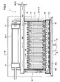
- 1 is a front sectional view showing a solid oxide fuel cell (SOFC) fuel cell module according to an embodiment of the present invention.
- FIG. 3 is a cross-sectional view taken along line III-III in FIG. 2.
- 1 is a partial cross-sectional view showing a fuel cell unit of a solid oxide fuel cell (SOFC) according to an embodiment of the present invention.
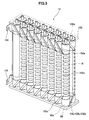
- 1 is a perspective view showing a fuel cell stack of a solid oxide fuel cell (SOFC) according to an embodiment of the present invention.
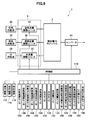
- 1 is a block diagram illustrating a solid oxide fuel cell (SOFC) according to an embodiment of the present invention.
- FIG. 10 is a time chart showing the operation at the time of normal startup with respect to the time chart showing the operation when the restart is executed based on the restart control flow of the solid oxide fuel cell (SOFC) according to the embodiment of the present invention. It is the figure compared with.
- SOFC solid oxide fuel cell
- FIG. 1 is an overall configuration diagram showing a solid oxide fuel cell (SOFC) according to an embodiment of the present invention.
- a solid oxide fuel cell (SOFC) 1 according to an embodiment of the present invention includes a fuel cell module 2 and an auxiliary unit 4.
- the fuel cell module 2 includes a housing 6, and a sealed space 8 is formed inside the housing 6 via a heat insulating material (not shown, but the heat insulating material is not an essential component and may not be necessary). Is formed. In addition, you may make it not provide a heat insulating material.
- a fuel cell assembly 12 that performs a power generation reaction with fuel gas and an oxidant (air) is disposed in a power generation chamber 10 that is a lower portion of the sealed space 8.
- the fuel cell assembly 12 includes ten fuel cell stacks 14 (see FIG. 5), and the fuel cell stack 14 includes 16 fuel cell unit 16 (see FIG. 4). Yes.
- the fuel cell assembly 12 has 160 fuel cell units 16, and all of these fuel cell units 16 are connected in series.
- a combustion chamber 18 is formed above the above-described power generation chamber 10 in the sealed space 8 of the fuel cell module 2.
- this combustion chamber 18 the remaining fuel gas that has not been used for the power generation reaction and the remaining oxidant (air) ) And combusted to generate exhaust gas.
- a reformer 20 for reforming the fuel gas is disposed above the combustion chamber 18, and the reformer 20 is heated to a temperature at which a reforming reaction can be performed by the combustion heat of the residual gas.
- an air heat exchanger 22 for receiving combustion heat and heating air is disposed above the reformer 20.
- the auxiliary unit 4 stores a pure water tank 26 that stores water from a water supply source 24 such as tap water and uses the filter to obtain pure water, and a water flow rate that adjusts the flow rate of the water supplied from the water storage tank.
- An adjustment unit 28 (such as a “water pump” driven by a motor) is provided.
- the auxiliary unit 4 also includes a gas shut-off valve 32 that shuts off the fuel gas supplied from a fuel supply source 30 such as city gas, a desulfurizer 36 for removing sulfur from the fuel gas, and a flow rate of the fuel gas.
- a fuel flow rate adjusting unit 38 (such as a “fuel pump” driven by a motor) is provided.
- the auxiliary unit 4 includes an electromagnetic valve 42 that shuts off air that is an oxidant supplied from the air supply source 40, a reforming air flow rate adjusting unit 44 that adjusts the flow rate of air, and a power generation air flow rate adjusting unit. 45 (such as an “air blower” driven by a motor), a first heater 46 for heating the reforming air supplied to the reformer 20, and a second for heating the power generating air supplied to the power generation chamber And a heater 48.
- the first heater 46 and the second heater 48 are provided in order to efficiently raise the temperature at startup, but may be omitted.
- a hot water production apparatus 50 to which exhaust gas is supplied is connected to the fuel cell module 2.
- the hot water production apparatus 50 is supplied with tap water from the water supply source 24, and the tap water is heated by the heat of the exhaust gas and supplied to a hot water storage tank of an external hot water heater (not shown).
- the fuel cell module 2 is provided with a control box 52 for controlling the amount of fuel gas supplied and the like. Furthermore, the fuel cell module 2 is connected to an inverter 54 that is a power extraction unit (power conversion unit) for supplying the power generated by the fuel cell module to the outside.
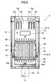
- FIG. 2 is a side sectional view showing a solid oxide fuel cell (SOFC) fuel cell module according to an embodiment of the present invention
- FIG. 3 is a sectional view taken along line III-III in FIG.
- the fuel cell assembly 12, the reformer 20, and the air heat exchange are sequentially performed from below.
- a vessel 22 is arranged.
- the reformer 20 is provided with a pure water introduction pipe 60 for introducing pure water and a reformed gas introduction pipe 62 for introducing reformed fuel gas and reforming air to the upstream end side thereof.
- a pure water introduction pipe 60 for introducing pure water
- a reformed gas introduction pipe 62 for introducing reformed fuel gas and reforming air to the upstream end side thereof.
- an evaporation unit 20a and a reforming unit 20b are formed in order from the upstream side, and the reforming unit 20b is filled with a reforming catalyst.
- the fuel gas and air mixed with the steam (pure water) introduced into the reformer 20 are reformed by the reforming catalyst filled in the reformer 20.
- the reforming catalyst a catalyst obtained by imparting nickel to the alumina sphere surface or a catalyst obtained by imparting ruthenium to the alumina sphere surface is appropriately used.
- a fuel gas supply pipe 64 is connected to the downstream end side of the reformer 20, and the fuel gas supply pipe 64 extends downward and further in an manifold 66 formed below the fuel cell assembly 12. It extends horizontally.
- a plurality of fuel supply holes 64 b are formed in the lower surface of the horizontal portion 64 a of the fuel gas supply pipe 64, and the reformed fuel gas is supplied into the manifold 66 from the fuel supply holes 64 b.
- a lower support plate 68 having a through hole for supporting the fuel cell stack 14 described above is attached above the manifold 66, and the fuel gas in the manifold 66 flows into the fuel cell unit 16. Supplied.
- the air heat exchanger 22 includes an air aggregation chamber 70 on the upstream side and two air distribution chambers 72 on the downstream side.
- the air aggregation chamber 70 and the air distribution chamber 72 include six air flow path tubes 74. Connected by.
- three air flow path pipes 74 form a set (74a, 74b, 74c, 74d, 74e, 74f), and the air in the air collecting chamber 70 is in each set. It flows into each air distribution chamber 72 from the air flow path pipe 74.
- the air flowing through the six air flow path pipes 74 of the air heat exchanger 22 is preheated by exhaust gas that burns and rises in the combustion chamber 18.
- An air introduction pipe 76 is connected to each of the air distribution chambers 72, the air introduction pipe 76 extends downward, and the lower end side communicates with the lower space of the power generation chamber 10, and the air that has been preheated in the power generation chamber 10. Is introduced.
- an exhaust gas chamber 78 is formed below the manifold 66. Further, as shown in FIG. 3, an exhaust gas passage 80 extending in the vertical direction is formed inside the front surface 6 a and the rear surface 6 b which are surfaces along the longitudinal direction of the housing 6, and the upper end side of the exhaust gas passage 80 is formed. Is in communication with the space in which the air heat exchanger 22 is disposed, and the lower end side is in communication with the exhaust gas chamber 78. Further, an exhaust gas discharge pipe 82 is connected to substantially the center of the lower surface of the exhaust gas chamber 78, and the downstream end of the exhaust gas discharge pipe 82 is connected to the above-described hot water producing apparatus 50 shown in FIG. As shown in FIG. 2, an ignition device 83 for starting combustion of fuel gas and air is provided in the combustion chamber 18.
- FIG. 4 is a partial cross-sectional view showing a fuel cell unit of a solid oxide fuel cell (SOFC) according to an embodiment of the present invention.
- the fuel cell unit 16 includes a fuel cell 84 and inner electrode terminals 86 respectively connected to the vertical ends of the fuel cell 84.
- the fuel cell 84 is a tubular structure that extends in the vertical direction, and includes a cylindrical inner electrode layer 90 that forms a fuel gas flow path 88 therein, a cylindrical outer electrode layer 92, an inner electrode layer 90, and an outer side.
- An electrolyte layer 94 is provided between the electrode layer 92 and the electrode layer 92.
- the inner electrode layer 90 is a fuel electrode through which fuel gas passes and becomes a ( ⁇ ) electrode, while the outer electrode layer 92 is an air electrode in contact with air and becomes a (+) electrode.
- the upper portion 90 a of the inner electrode layer 90 includes an outer peripheral surface 90 b and an upper end surface 90 c exposed to the electrolyte layer 94 and the outer electrode layer 92.
- the inner electrode terminal 86 is connected to the outer peripheral surface 90b of the inner electrode layer 90 through a conductive sealing material 96, and is further in direct contact with the upper end surface 90c of the inner electrode layer 90, thereby Electrically connected.
- a fuel gas passage 98 communicating with the fuel gas passage 88 of the inner electrode layer 90 is formed at the center of the inner electrode terminal 86.
- the inner electrode layer 90 includes, for example, a mixture of Ni and zirconia doped with at least one selected from rare earth elements such as Ca, Y, and Sc, and Ni and ceria doped with at least one selected from rare earth elements.
- the mixture is formed of at least one of Ni and a mixture of lanthanum garade doped with at least one selected from Sr, Mg, Co, Fe, and Cu.
- the electrolyte layer 94 is, for example, zirconia doped with at least one selected from rare earth elements such as Y and Sc, ceria doped with at least one selected from rare earth elements, lanthanum gallate doped with at least one selected from Sr and Mg, Formed from at least one of the following.
- the outer electrode layer 92 includes, for example, lanthanum manganite doped with at least one selected from Sr and Ca, lanthanum ferrite doped with at least one selected from Sr, Co, Ni and Cu, Sr, Fe, Ni and Cu. It is formed from at least one of lanthanum cobaltite doped with at least one selected from the group consisting of silver and silver.
- FIG. 5 is a perspective view showing a fuel cell stack of a solid oxide fuel cell (SOFC) according to an embodiment of the present invention.
- the fuel cell stack 14 includes 16 fuel cell units 16, and the lower end side and the upper end side of these fuel cell units 16 are a ceramic lower support plate 68 and an upper side, respectively. It is supported by the support plate 100.
- the lower support plate 68 and the upper support plate 100 are formed with through holes 68a and 100a through which the inner electrode terminal 86 can pass.
- the current collector 102 includes a fuel electrode connection portion 102a that is electrically connected to an inner electrode terminal 86 attached to the inner electrode layer 90 that is a fuel electrode, and an entire outer peripheral surface of the outer electrode layer 92 that is an air electrode. And an air electrode connecting portion 102b electrically connected to each other.
- the air electrode connecting portion 102b is formed of a vertical portion 102c extending in the vertical direction on the surface of the outer electrode layer 92 and a plurality of horizontal portions 102d extending in a horizontal direction along the surface of the outer electrode layer 92 from the vertical portion 102c. Has been.
- the fuel electrode connecting portion 102a is linearly directed obliquely upward or obliquely downward from the vertical portion 102c of the air electrode connecting portion 102b toward the inner electrode terminal 86 positioned in the vertical direction of the fuel cell unit 16. It extends.
- the inner electrode terminals 86 at the upper end and the lower end of the two fuel cell units 16 located at the ends of the fuel cell stack 14 are external terminals, respectively. 104 is connected. These external terminals 104 are connected to the external terminals 104 (not shown) of the fuel cell unit 16 at the end of the adjacent fuel cell stack 14, and as described above, the 160 fuel cell units 16 Everything is connected in series.
- FIG. 6 is a block diagram illustrating a solid oxide fuel cell (SOFC) according to an embodiment of the present invention.
- the solid oxide fuel cell 1 includes a control unit 110, and the control unit 110 includes operation buttons such as “ON” and “OFF” for operation by the user.
- a device 112 a display device 114 for displaying various data such as a power generation output value (wattage), and a notification device 116 for issuing an alarm (warning) in an abnormal state are connected.
- the notification device 116 may be connected to a remote management center and notify the management center of an abnormal state.
- the combustible gas detection sensor 120 is for detecting a gas leak, and is attached to the fuel cell module 2 and the auxiliary unit 4.
- the CO detection sensor 122 detects whether or not CO in the exhaust gas originally discharged to the outside through the exhaust gas passage 80 or the like leaks to an external housing (not shown) that covers the fuel cell module 2 and the auxiliary unit 4. Is to do.
- the hot water storage state detection sensor 124 is for detecting the temperature and amount of hot water in a water heater (not shown).
- the power state detection sensor 126 is for detecting the current and voltage of the inverter 54 and the distribution board (not shown).
- the power generation air flow rate detection sensor 128 is for detecting the flow rate of power generation air supplied to the power generation chamber 10.
- the reforming air flow sensor 130 is for detecting the flow rate of the reforming air supplied to the reformer 20.
- the fuel flow sensor 132 is for detecting the flow rate of the fuel gas supplied to the reformer 20.
- the water flow rate sensor 134 is for detecting the flow rate of pure water (steam) supplied to the reformer 20.
- the water level sensor 136 is for detecting the water level of the pure water tank 26.
- the pressure sensor 138 is for detecting the pressure on the upstream side outside the reformer 20.
- the exhaust temperature sensor 140 is for detecting the temperature of the exhaust gas flowing into the hot water production apparatus 50.
- the power generation chamber temperature sensor 142 is provided on the front side and the back side in the vicinity of the fuel cell assembly 12, and detects the temperature in the vicinity of the fuel cell stack 14 to thereby detect the fuel cell stack. 14 (ie, the fuel cell 84 itself) is estimated.
- the combustion chamber temperature sensor 144 is for detecting the temperature of the combustion chamber 18.
- the exhaust gas chamber temperature sensor 146 is for detecting the temperature of the exhaust gas in the exhaust gas chamber 78.
- the reformer temperature sensor 148 is for detecting the temperature of the reformer 20, and calculates the temperature of the reformer 20 from the inlet temperature and the outlet temperature of the reformer 20.
- the outside air temperature sensor 150 is for detecting the temperature of the outside air when the solid oxide fuel cell (SOFC) is disposed outdoors. Further, a sensor for measuring the humidity or the like of the outside air may be provided.
- SOFC solid oxide fuel cell
- Signals from these sensors are sent to the control unit 110, and the control unit 110, based on data based on these signals, the water flow rate adjustment unit 28, the fuel flow rate adjustment unit 38, the reforming air flow rate adjustment unit 44, A control signal is sent to the power generation air flow rate adjusting unit 45 to control each flow rate in these units. Further, the control unit 110 sends a control signal to the inverter 54 to control the power supply amount.
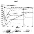
- FIG. 7 is a time chart showing the operation at the time of startup of the solid oxide fuel cell (SOFC) according to one embodiment of the present invention.
- reforming air is supplied from the reforming air flow rate adjustment unit 44 to the reformer 20 of the fuel cell module 2 via the first heater 46.
- the power generation air is supplied from the power generation air flow rate adjustment unit 45 to the air heat exchanger 22 of the fuel cell module 2 via the second heater 48, and this power generation air is supplied to the power generation chamber 10 and the combustion chamber.
- the fuel gas is also supplied from the fuel flow rate adjustment unit 38, and the fuel gas mixed with the reforming air passes through the reformer 20, the fuel cell stack 14, and the fuel cell unit 16, and It reaches the combustion chamber 18.
- the ignition device 83 is ignited to burn the fuel gas and air (reforming air and power generation air) in the combustion chamber 18.
- Exhaust gas is generated by the combustion of the fuel gas and air, and the power generation chamber 10 is warmed by the exhaust gas, and when the exhaust gas rises in the sealed space 8 of the fuel cell module 2, The fuel gas containing the reforming air is warmed, and the power generation air in the air heat exchanger 22 is also warmed.
- the fuel gas mixed with the reforming air is supplied to the reformer 20 by the fuel flow rate adjusting unit 38 and the reforming air flow rate adjusting unit 44.
- the heated fuel gas is supplied to the lower side of the fuel cell stack 14 through the fuel gas supply pipe 64, whereby the fuel cell stack 14 is heated from below, and the combustion chamber 18 also has the fuel gas and air.
- the fuel cell stack 14 is also heated from above, and as a result, the fuel cell stack 14 can be heated substantially uniformly in the vertical direction. Even if the partial oxidation reforming reaction POX proceeds, the combustion reaction between the fuel gas and air continues in the combustion chamber 18.
- the reformer temperature sensor 148 detects that the reformer 20 has reached a predetermined temperature (for example, 600 ° C.) after the partial oxidation reforming reaction POX is started, the water flow rate adjustment unit 28 and the fuel flow rate adjustment unit 38 are detected.
- the reforming air flow rate adjusting unit 44 supplies a gas in which fuel gas, reforming air, and water vapor are mixed in advance to the reformer 20.
- an autothermal reforming reaction ATR in which the partial oxidation reforming reaction POX described above and a steam reforming reaction SR described later are used proceeds. Since the autothermal reforming reaction ATR is thermally balanced internally, the reaction proceeds in the reformer 20 in a thermally independent state.
- the reformer temperature sensor 146 detects that the reformer 20 has reached a predetermined temperature (for example, 700 ° C.) after the start of the autothermal reforming reaction ATR shown in Formula (2), the reforming air flow rate The supply of reforming air by the adjustment unit 44 is stopped, and the supply of water vapor by the water flow rate adjustment unit 28 is increased. As a result, the reformer 20 is supplied with a gas that does not contain air and contains only fuel gas and water vapor, and the steam reforming reaction SR of formula (3) proceeds in the reformer 20.
- a predetermined temperature for example, 700 ° C.
- this steam reforming reaction SR is an endothermic reaction, the reaction proceeds while maintaining a heat balance with the combustion heat from the combustion chamber 18. At this stage, since the fuel cell module 2 is in the final stage of start-up, the power generation chamber 10 is heated to a sufficiently high temperature. Therefore, even if the endothermic reaction proceeds, the power generation chamber 10 is greatly reduced in temperature. There is nothing. Even if the steam reforming reaction SR proceeds, the combustion reaction continues in the combustion chamber 18.
- the partial oxidation reforming reaction POX, the autothermal reforming reaction ATR, and the steam reforming reaction SR proceed in sequence, so that the inside of the power generation chamber 10 The temperature gradually increases.
- the circuit including the fuel cell module 2 is closed, and the fuel cell Power generation by the module 2 is started, so that a current flows in the circuit. Due to the power generation of the fuel cell module 2, the fuel cell 84 itself also generates heat, and the temperature of the fuel cell 84 also rises.
- the rated rated temperature at which the fuel cell module 2 is operated becomes, for example, 600 ° C. to 800 ° C.
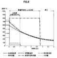
- FIG. 8 is a time chart showing the operation when the solid oxide fuel cell (SOFC) is stopped according to this embodiment.
- the fuel flow rate adjustment unit 38 and the water flow rate adjustment unit 28 are operated to supply fuel gas and water vapor to the reformer 20. Reduce the amount.
- the amount of fuel gas and water vapor supplied to the reformer 20 is reduced, and at the same time, the fuel cell module for generating air by the reforming air flow rate adjusting unit 44
- the supply amount into 2 is increased, the fuel cell assembly 12 and the reformer 20 are cooled by air, and these temperatures are lowered.
- the temperature of the power generation chamber decreases to a predetermined temperature, for example, 400 ° C.
- the supply of fuel gas and steam to the reformer 20 is stopped, and the steam reforming reaction SR of the reformer 20 is ended.
- This supply of power generation air continues until the temperature of the reformer 20 decreases to a predetermined temperature, for example, 200 ° C., and when this temperature is reached, the power generation air from the power generation air flow rate adjustment unit 45 is supplied. Stop supplying.
- the steam reforming reaction SR by the reformer 20 and the cooling by the power generation air are used in combination.
- the operation of the fuel cell module can be stopped.
- FIG. 9 shows the fuel flow rate, the reforming air flow rate, the power generation air flow rate, the water flow rate, and the flow rate of the solid oxide fuel cell (SOFC) according to the present embodiment in each operation state during normal startup and restart. It is a data table which shows the transition temperature conditions of a reformer and a stack.
- the solid oxide fuel cell (SOFC) according to the present embodiment has the same operation as the operation at the time of starting the solid oxide fuel cell (SOFC) according to the present embodiment shown in FIG. Is controlled as an operation at the normal start of operation (hereinafter referred to as “normal start mode”).
- the solid oxide fuel cell (SOFC) according to the present embodiment starts operation (so-called “restart” in a state where the solid oxide fuel cell (SOFC) according to the present embodiment shown in FIG. 8 is stopped. )),
- a restart control mode hereinafter referred to as “restart mode” is executed to restart the operation when requested, and each of these restart modes is executed based on a corresponding restart control flow. It has come to be. Details of the normal startup mode and the restart mode in FIG. 9 will be described later.
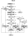
- FIG. 10 is a flowchart showing a restart control flow for restarting a solid oxide fuel cell (SOFC) according to an embodiment of the present invention.
- S indicates each step. First, in S1, it is determined whether or not the fuel cell module 2 is in a stop operation. If the fuel cell module 2 is in a stop operation, the process proceeds to S2 and it is determined whether or not a restart is requested.
- the process proceeds to S3, where the reforming which is part of the reforming state temperature detecting means for detecting the reforming state temperature for changing the reforming state by the reformer 20 is performed.
- the process proceeds to S4, and the reformed state temperature for changing the reformed state by the reformer 20 is detected.
- the stack temperature Ts which is the temperature in the vicinity of the fuel cell stack 14 (that is, the fuel cell 84 itself), is measured by the power generation chamber temperature sensor 142 which is a part of the reforming state temperature detecting means.
- it progresses to S5 and it is determined whether the reformer temperature Tr is 500 degreeC or more.
- S5 when it is determined that the reformer temperature Tr is not 500 ° C. or higher, the process proceeds to S6, and it is determined whether or not the reformer temperature Tr is less than 200 ° C. If it is determined in S6 that the reformer temperature Tr is not less than 200 ° C., that is, the reformer temperature Tr is 200 ° C. or more and less than 500 ° C., the process proceeds to S7, where the reformer temperature Tr is 200 ° C. or more. It is determined whether the temperature is less than 230 ° C.
- the process proceeds to S8, and the fuel gas from the ignition device 83 The ignition is prohibited, the restart is put on hold, and the stop operation is continued. Then, when the reformer temperature Tr decreases to a temperature range of 200 ° C. or higher and lower than 230 ° C., the process proceeds from S7 to S9, and ignition of the fuel gas by the ignition device 83 is started. “Restart POX” by “restart mode” in the data table is executed.
- the process proceeds to S12, in which it is determined whether or not the stack temperature Ts measured by the power generation chamber temperature sensor 142 is 600 ° C. or higher. To do. If it is determined in S12 that the stack temperature Ts is 600 ° C. or higher, the process proceeds to S13, and “normal start SR” is executed in the “restart mode” in the data table shown in FIG. On the other hand, if it is determined in S12 that the stack temperature Ts is not 600 ° C. or higher, that is, the reformer temperature Tr is 600 ° C. or higher, but the stack temperature Ts is lower than 600 ° C., the process proceeds to S11. Then, the “normal activation ATR” is executed by the “reactivation mode” in the data table shown in FIG.
- S1 it is determined whether or not the fuel cell module 2 is in a stop operation. If the fuel cell module 2 is not in a stop operation, the process proceeds to S14 to determine whether or not there is a request for restart based on misfire during startup. To do. If it is determined in S14 that there is a restart request based on misfire, and if it is determined in S6 that the reformer temperature Tr is lower than 200 ° C., the value of the temperature sensor may be apparently high. Since not all of the fuel cell modules have been in a high temperature state for a long time, there is no situation in which heat is uniformly stored, so there is no situation in which restart control based on residual heat is possible, so the process proceeds to S15 and the data shown in FIG. Reboot is executed based on the “normal start mode” in the table.
- FIG. 11 is a time chart showing the operation at the time of normal startup in the time chart showing the operation when the restart is executed based on the restart control flow of the solid oxide fuel cell (SOFC) according to the present embodiment shown in FIG. It is the figure compared with the chart.
- the upper time chart of FIG. 11 is a time chart showing the normal start operation of the solid oxide fuel cell (SOFC) when the “normal start mode” in the data table shown in FIG. 9 is executed.
- 11 is a time chart showing the restart operation of the solid oxide fuel cell (SOFC) when the “restart mode” in the data table shown in FIG. 9 is executed.
- a data table relating to the “normal start mode” and the “restart mode” shown in FIG. 11 is compared with the operation at the time of restart in the “restart mode” of the solid oxide fuel cell (SOFC) of the present embodiment shown in FIG. 11 compared with the operation at the time of normal start in the “normal start mode”. While explaining.
- the column “state” of “normal start mode” shown in FIG. 9 represents each operation state at the time of normal start from the upper stage toward the lower stage, and for each operation state, “at the time of ignition”. , “Combustion operation”, “normal start POX”, “normal start ATR”, and “normal start SR”.
- “Combustion operation” “normal start POX”, “normal start ATR”, and “normal start SR”.
- the time of “ignition” is t1
- “normal start POX”, “normal start ATR”, and “normal start” The times when shifting to the “start-up SR” are t2, t3, and t4, respectively, the temperature of the reformer 20 detected by the reformer temperature sensor 148 at the time t is Tr (t), and power generation is performed at the time t.
- Tr the temperature of the reformer 20 detected by the reformer temperature sensor 148 at the time t
- power generation is performed at the time t.
- the stack temperature measured by the room temperature sensor 142 be Ts (t).
- the temperature of the reformer 20 detected by the mass temperature sensor 148 is “ignition temperature Tr (t1)”
- an operation state of “normal start SR” in the “normal start mode” indicates that the temperature Tr (t) of the reformer 20 detected by the reformer temperature sensor 148 is a predetermined steady state temperature Tr (t4) at 650 ° C. or higher. And when the stack temperature Ts measured by the power generation chamber temperature sensor 142 is 600 ° C. or higher, the startup is controlled in the control band for executing SR (hereinafter referred to as “normal startup mode SR control band B4”). Yes.
- the column “fuel flow rate” shown in FIG. 9 indicates the flow rate [L / min] of the fuel gas supplied from the fuel flow rate adjustment unit 38 that is the fuel gas supply means of the auxiliary unit 4 to the reformer 20. ing. Further, the column “reforming air flow rate” shown in FIG. 9 includes a first oxidant gas heating unit from the air flow rate adjustment unit 44 that is an oxidant gas supply unit of the auxiliary unit 4 in each operation state. The flow rate [L / min] of the oxidizing gas (reforming air) supplied to the reformer 20 through the heater 46 is shown.
- the column “power generation air flow rate” shown in FIG. 9 indicates the power generation air supplied to the power generation chamber 10 from the power generation air flow rate adjustment unit 45 of the auxiliary unit 4 via the second heater 48 in each operation state.
- the flow rate [L / min] is shown.
- the column of “water flow rate” shown in FIG. 9 is reformed from the water flow rate adjustment unit 28 which is a water supply means that generates pure water of the auxiliary unit 4 and supplies it to the reformer 20 in each operation state.
- the flow rate [cc / min] of pure water supplied to the vessel 20 is shown.
- “reformer temperature” of “transition temperature condition” in the “normal start POX” status column of “normal start mode” is indicated as “600 ° C. or higher”, and “stack temperature” is “250 ° C.” This indicates that the temperature Tr (t) of the reformer 20 detected by the reformer temperature sensor 148 is 600 ° C. or higher, and the stack temperature measured by the power generation chamber temperature sensor 142 is displayed. When Ts becomes 250 ° C. or higher, it means that the operation state of “normal start POX” is shifted to the operation state of “normal start ATR”.
- the operation state of “at the time of ignition” in the “restart mode” shown in FIG. 9 is the modified state detected by the reformer temperature sensor 148 when the restart is requested during the stop operation of the fuel cell module 2.
- the ignition device 83 is ignited and immediately after the fuel gas is ignited, The operation state is shifted to “POX” (see S7 and S9 in FIG. 10).
- the “fuel flow rate” of “at the time of ignition” in the “restart mode” shown in FIG. 9 is 5.5 [L / min]
- the “fuel flow rate” at the time of “ignition” in the “normal start mode” (6 0.0 [L / min]).
- the temperature Tr (t11) of the reformer 20 detected by the reformer temperature sensor 148 is a predetermined temperature.
- the ignition device 83 is ignited, and after the fuel gas is ignited, restart immediately in the control band (hereinafter referred to as “restart mode POX control band B12”) in which POX is executed. I have control.
- the operation state of the “restart POX” executed in the restart mode POX control band B12 in the “restart mode” is “normal start POX” executed in the normal start mode POX control band B2 in the “normal start mode”. It is in a different driving state.
- the temperature band of the reformer 20 in which “restart POX” is executed in the restart mode POX control band B12 of “restart mode” (hereinafter “restart POX temperature band W12”) is: Temperature range (200 ° C. ⁇ Tr (t) ⁇ 600 ° C.) on the lower temperature side than the normal startup POX temperature zone W2 (300 ° C. ⁇ Tr (t) ⁇ 600 ° C.) in which “normal startup POX” is executed in the normal startup mode POX control zone B2 of “normal startup mode” C ⁇ Tr (t) ⁇ 230 ° C.).
- the “fuel flow rate” in the operation state of “restart POX” in “restart mode” is 5.5 [L / min], and “ignition” and “combustion operation” in “normal start mode” are performed.
- the “fuel flow rate” (5.0 [L / min]) in the “normal start POX” operating state in the “normal start mode” is smaller than the “fuel flow rate” in the state (6.0 [L / min]). More than that.
- the “reforming air flow rate” in the operation state of “restart POX” in “restart mode” is 17.0 [L / min]
- the operation state of “normal start POX” in “normal start mode” is 17.0 [L / min]
- the operation state of “normal start POX” in “normal start mode” is 17.0 [L / min]
- the operation state of “ignition prohibited” in the “restart mode” shown in FIG. 9 prohibits ignition of the fuel gas by the ignition device 83, prohibits restart, and continues the stop operation ( (Hereinafter referred to as “restart mode ignition prohibition control band”) controls the restart (see S8 in FIG. 10). More specifically, the temperature band of the reformer 20 in which “ignition prohibition” is executed in the restart mode ignition prohibition control band of “restart mode” (hereinafter “ignition prohibition temperature band”) is “restart In the “mode” restart POX temperature zone W12, the temperature zone is 230 ° C. or higher and lower than 500 ° C. on the higher temperature side.
- the portion of 300 ° C. or more and less than 500 ° C. in the ignition prohibition temperature band of “restart mode” is the normal start POX of “normal start mode”.
- the “normal startup mode” “normal startup POX” is not executed even though it overlaps with a part of the temperature zone in the temperature band W2 (300 ° C. ⁇ Tr (t) ⁇ 600 ° C.).
- restart mode ignition prohibition control zone of the “restart mode” when the reformer temperature Tr falls from within the ignition prohibition temperature zone (230 ° C. ⁇ Tr ⁇ 500 ° C.) to less than 230 ° C., the ignition device 83 is started, and immediately after this ignition, “restart POX” in “restart mode” in the data table shown in FIG. 9 is executed (see S7 and S9 in FIG. 10). .
- the operation state of “normal start ATR” in “restart mode” shown in S11 of FIG. 9 and FIG. 10 is the normal start POX temperature band in which the temperature Tr (t) of the reformer 20 is “normal start mode”. It is in the temperature band corresponding to W2 and at a temperature higher than the ignition prohibited temperature band in the “restart mode” and at a temperature higher than 500 ° C. and lower than 600 ° C. (hereinafter, in the “restart ATR temperature band W13”)
- the restart is controlled in a control band (hereinafter referred to as “restart mode ATR control band B13”) that executes the same ATR as the “normal start ATR” in the “normal start mode”.
- restart mode SR control band B14 a control band that executes the same SR as the “normal start SR” of the “normal start mode”.
- the time t13 when shifting from “restart POX” in “restart mode” to “normal start ATR” is “normal start POX” in “normal start mode”.
- the time is less than the time t3 when shifting to “ATR”.
- the temperature Tr (t) of the reformer 20 is “normally started” by stopping the operation of the fuel cell module 2.
- the temperature is within the temperature range corresponding to the normal startup POX temperature range W2 of the “mode”
- the residual heat remaining in the fuel cell stack 14 and the reformer 20 is actively used, so that the reformer 20 Even when the temperature Tr (t) is within the normal startup POX temperature band W2, the execution of the “normal startup POX” in the normal startup mode POX control band B2 in the “normal startup mode” is prohibited.
- reactivation control different from “normally activated POX” can be executed.
- the oxidation or abnormality of the fuel cell 84 is performed.
- the burden on the fuel cell 84 due to the high temperature can be reduced, and the durability of the fuel cell 84 can be improved.
- the remaining heat remaining in the fuel cell 84 and the reformer 20 is actively used to execute the restart control different from the “normal start POX” in the “normal start mode”, thereby reducing the start time. It can be greatly shortened. Further, for example, when a restart is performed based on a misfire at the time of starting (see S14 and S15 in FIG. 10), the restart in the “restart mode” is prohibited and the start in the “normal start mode” is performed. Since it can perform, the damage of the fuel cell unit 16 can be suppressed.
- the temperature is higher than the ignition prohibition temperature band (230 ° C. ⁇ Tr ⁇ 500 ° C.) in the “restart mode”.
- the “restart mode” restart ATR temperature band W13 (500 ° C. ⁇ Tr ⁇ 600 ° C.), restart by the same ATR as the normal start ATR of the normal start mode ATR control band B3 of the “normal start mode”
- the temperature range for executing the “normal start ATR” in the “restart mode” is a range equal to or higher than a predetermined temperature in the POX temperature band W2 of the “normal start POX” in the “normal start mode” (500 ° C. ⁇ Tr ⁇ 600
- the temperature can be increased in a short time in a stable state while suppressing the influence on the fuel battery cell 84. That is, the POX temperature band W2 (300 ° C.
- restart POX control band B12 in which “restart POX” of “restart mode” is executed.
- “restart POX” of “restart mode” is executed.
- “Restart POX” can be executed by (reforming air), and a large amount of oxidant gas is used to affect the fuel cell stack 14 due to residual heat. It is possible to prevent the theft.
Landscapes
- Chemical & Material Sciences (AREA)
- Chemical Kinetics & Catalysis (AREA)
- Engineering & Computer Science (AREA)
- Sustainable Development (AREA)
- Sustainable Energy (AREA)
- Life Sciences & Earth Sciences (AREA)
- Manufacturing & Machinery (AREA)
- Electrochemistry (AREA)
- General Chemical & Material Sciences (AREA)
- Organic Chemistry (AREA)
- Health & Medical Sciences (AREA)
- General Health & Medical Sciences (AREA)
- Combustion & Propulsion (AREA)
- Inorganic Chemistry (AREA)
- Fuel Cell (AREA)
Priority Applications (3)
| Application Number | Priority Date | Filing Date | Title |
|---|---|---|---|
| CN201080019134.8A CN102414894B (zh) | 2009-03-31 | 2010-03-31 | 固体电解质型燃料电池 |
| US13/262,014 US8927162B2 (en) | 2009-03-31 | 2010-03-31 | Solid oxide fuel cell system performing different restart operations depending on operation temperature |
| EP10758810.5A EP2416418B1 (en) | 2009-03-31 | 2010-03-31 | Solid electrolyte fuel cell |
Applications Claiming Priority (2)
| Application Number | Priority Date | Filing Date | Title |
|---|---|---|---|
| JP2009-087413 | 2009-03-31 | ||
| JP2009087413A JP4863171B2 (ja) | 2009-03-31 | 2009-03-31 | 固体電解質型燃料電池 |
Publications (1)
| Publication Number | Publication Date |
|---|---|
| WO2010114039A1 true WO2010114039A1 (ja) | 2010-10-07 |
Family
ID=42828328
Family Applications (1)
| Application Number | Title | Priority Date | Filing Date |
|---|---|---|---|
| PCT/JP2010/055906 Ceased WO2010114039A1 (ja) | 2009-03-31 | 2010-03-31 | 固体電解質型燃料電池 |
Country Status (5)
| Country | Link |
|---|---|
| US (1) | US8927162B2 (enExample) |
| EP (1) | EP2416418B1 (enExample) |
| JP (1) | JP4863171B2 (enExample) |
| CN (1) | CN102414894B (enExample) |
| WO (1) | WO2010114039A1 (enExample) |
Cited By (1)
| Publication number | Priority date | Publication date | Assignee | Title |
|---|---|---|---|---|
| JP2013125627A (ja) * | 2011-12-14 | 2013-06-24 | Panasonic Corp | 燃料電池発電システム |
Families Citing this family (13)
| Publication number | Priority date | Publication date | Assignee | Title |
|---|---|---|---|---|
| JP4761259B2 (ja) * | 2009-05-28 | 2011-08-31 | Toto株式会社 | 固体電解質型燃料電池 |
| JP4707023B2 (ja) * | 2009-09-30 | 2011-06-22 | Toto株式会社 | 固体電解質型燃料電池 |
| EP2624348B1 (en) | 2010-09-30 | 2016-06-15 | Toto Ltd. | Solid oxide fuel cell device |
| JP5561655B2 (ja) | 2010-09-30 | 2014-07-30 | Toto株式会社 | 固体酸化物形燃料電池装置 |
| JP5721825B2 (ja) * | 2011-05-30 | 2015-05-20 | 京セラ株式会社 | 燃料電池装置 |
| JP5902581B2 (ja) * | 2012-08-02 | 2016-04-13 | 本田技研工業株式会社 | 燃料電池システム及びその制御方法 |
| JP6183775B2 (ja) * | 2013-03-25 | 2017-08-23 | Toto株式会社 | 固体酸化物型燃料電池システム |
| JP6183774B2 (ja) * | 2013-03-25 | 2017-08-23 | Toto株式会社 | 固体酸化物型燃料電池システム |
| JP2015127998A (ja) * | 2013-12-27 | 2015-07-09 | Toto株式会社 | 固体酸化物型燃料電池システム |
| JP2015127999A (ja) * | 2013-12-27 | 2015-07-09 | Toto株式会社 | 固体酸化物型燃料電池システム |
| DE102014218726A1 (de) * | 2014-09-18 | 2016-04-07 | Robert Bosch Gmbh | Brennstoffzellenvorrichtung mit verbessertem Anodengasprozessor |
| KR102587217B1 (ko) * | 2016-05-24 | 2023-10-12 | 주식회사 미코파워 | 연료전지 시스템 |
| US10840528B2 (en) | 2016-12-19 | 2020-11-17 | Cummins Enterprise Llc | Method and apparatus for detecting damage in fuel cell stacks, and adjusting operational characteristics in fuel cell systems |
Citations (8)
| Publication number | Priority date | Publication date | Assignee | Title |
|---|---|---|---|---|
| JP2003095611A (ja) * | 2001-09-19 | 2003-04-03 | Toyota Motor Corp | 水素生成装置の起動方法 |
| JP2004319420A (ja) | 2003-02-25 | 2004-11-11 | Kyocera Corp | 燃料電池及びその運転方法 |
| JP2004338975A (ja) * | 2003-05-13 | 2004-12-02 | Mitsubishi Kakoki Kaisha Ltd | 水素製造装置の起動方法 |
| JP2006086016A (ja) * | 2004-09-16 | 2006-03-30 | Kyocera Corp | 固体酸化物形燃料電池の運転方法 |
| JP2006190605A (ja) * | 2005-01-07 | 2006-07-20 | Nippon Oil Corp | 固体電解質形燃料電池システムの起動方法 |
| JP2006269196A (ja) | 2005-03-23 | 2006-10-05 | Nissan Motor Co Ltd | 燃料電池システム |
| JP2007311072A (ja) * | 2006-05-16 | 2007-11-29 | Acumentrics Corp | 燃料電池システム及びその運転方法 |
| JP2008243597A (ja) * | 2007-03-27 | 2008-10-09 | Kyocera Corp | 燃料電池装置 |
Family Cites Families (2)
| Publication number | Priority date | Publication date | Assignee | Title |
|---|---|---|---|---|
| JP4232528B2 (ja) * | 2003-05-13 | 2009-03-04 | 住友ベークライト株式会社 | 合わせガラス |
| US20110053017A1 (en) * | 2007-08-29 | 2011-03-03 | Kyocera Corporation | Fuel Cell Apparatus |
-
2009
- 2009-03-31 JP JP2009087413A patent/JP4863171B2/ja not_active Expired - Fee Related
-
2010
- 2010-03-31 WO PCT/JP2010/055906 patent/WO2010114039A1/ja not_active Ceased
- 2010-03-31 EP EP10758810.5A patent/EP2416418B1/en not_active Not-in-force
- 2010-03-31 CN CN201080019134.8A patent/CN102414894B/zh not_active Expired - Fee Related
- 2010-03-31 US US13/262,014 patent/US8927162B2/en not_active Expired - Fee Related
Patent Citations (8)
| Publication number | Priority date | Publication date | Assignee | Title |
|---|---|---|---|---|
| JP2003095611A (ja) * | 2001-09-19 | 2003-04-03 | Toyota Motor Corp | 水素生成装置の起動方法 |
| JP2004319420A (ja) | 2003-02-25 | 2004-11-11 | Kyocera Corp | 燃料電池及びその運転方法 |
| JP2004338975A (ja) * | 2003-05-13 | 2004-12-02 | Mitsubishi Kakoki Kaisha Ltd | 水素製造装置の起動方法 |
| JP2006086016A (ja) * | 2004-09-16 | 2006-03-30 | Kyocera Corp | 固体酸化物形燃料電池の運転方法 |
| JP2006190605A (ja) * | 2005-01-07 | 2006-07-20 | Nippon Oil Corp | 固体電解質形燃料電池システムの起動方法 |
| JP2006269196A (ja) | 2005-03-23 | 2006-10-05 | Nissan Motor Co Ltd | 燃料電池システム |
| JP2007311072A (ja) * | 2006-05-16 | 2007-11-29 | Acumentrics Corp | 燃料電池システム及びその運転方法 |
| JP2008243597A (ja) * | 2007-03-27 | 2008-10-09 | Kyocera Corp | 燃料電池装置 |
Non-Patent Citations (1)
| Title |
|---|
| See also references of EP2416418A4 * |
Cited By (1)
| Publication number | Priority date | Publication date | Assignee | Title |
|---|---|---|---|---|
| JP2013125627A (ja) * | 2011-12-14 | 2013-06-24 | Panasonic Corp | 燃料電池発電システム |
Also Published As
| Publication number | Publication date |
|---|---|
| EP2416418A1 (en) | 2012-02-08 |
| US20120028143A1 (en) | 2012-02-02 |
| US8927162B2 (en) | 2015-01-06 |
| JP4863171B2 (ja) | 2012-01-25 |
| JP2010238623A (ja) | 2010-10-21 |
| CN102414894A (zh) | 2012-04-11 |
| EP2416418A4 (en) | 2013-01-16 |
| CN102414894B (zh) | 2015-09-16 |
| EP2416418B1 (en) | 2015-10-14 |
Similar Documents
| Publication | Publication Date | Title |
|---|---|---|
| JP4863171B2 (ja) | 固体電解質型燃料電池 | |
| JP5418960B2 (ja) | 固体電解質型燃料電池 | |
| JP6044771B2 (ja) | 固体酸化物型燃料電池 | |
| JP4650799B2 (ja) | 固体電解質型燃料電池 | |
| JP4761260B2 (ja) | 固体電解質型燃料電池 | |
| JP4707023B2 (ja) | 固体電解質型燃料電池 | |
| JP6070923B2 (ja) | 固体酸化物型燃料電池 | |
| JP6048662B2 (ja) | 固体酸化物型燃料電池 | |
| WO2012043645A1 (ja) | 燃料電池装置 | |
| JP2010277843A (ja) | 固体電解質型燃料電池 | |
| JP2011009136A (ja) | 固体電解質型燃料電池 | |
| JP2013218861A (ja) | 固体酸化物型燃料電池 | |
| JP2012079409A (ja) | 燃料電池システム | |
| JP5565759B2 (ja) | 固体電解質型燃料電池 | |
| JP5594648B2 (ja) | 固体酸化物形燃料電池装置 | |
| JP5517096B2 (ja) | 固体電解質型燃料電池 | |
| JP5505872B2 (ja) | 固体電解質型燃料電池 | |
| JP2013206578A (ja) | 固体酸化物型燃料電池 | |
| JP2012079420A (ja) | 固体酸化物形燃料電池装置 | |
| JP6080090B2 (ja) | 固体酸化物型燃料電池 |
Legal Events
| Date | Code | Title | Description |
|---|---|---|---|
| WWE | Wipo information: entry into national phase |
Ref document number: 201080019134.8 Country of ref document: CN |
|
| 121 | Ep: the epo has been informed by wipo that ep was designated in this application |
Ref document number: 10758810 Country of ref document: EP Kind code of ref document: A1 |
|
| WWE | Wipo information: entry into national phase |
Ref document number: 13262014 Country of ref document: US |
|
| NENP | Non-entry into the national phase |
Ref country code: DE |
|
| WWE | Wipo information: entry into national phase |
Ref document number: 2010758810 Country of ref document: EP |