EP2416418B1 - Solid electrolyte fuel cell - Google Patents
Solid electrolyte fuel cell Download PDFInfo
- Publication number
- EP2416418B1 EP2416418B1 EP10758810.5A EP10758810A EP2416418B1 EP 2416418 B1 EP2416418 B1 EP 2416418B1 EP 10758810 A EP10758810 A EP 10758810A EP 2416418 B1 EP2416418 B1 EP 2416418B1
- Authority
- EP
- European Patent Office
- Prior art keywords
- temperature
- pox
- restart
- reforming
- fuel cell
- Prior art date
- Legal status (The legal status is an assumption and is not a legal conclusion. Google has not performed a legal analysis and makes no representation as to the accuracy of the status listed.)
- Not-in-force
Links
Images


Classifications
-
- H—ELECTRICITY
- H01—ELECTRIC ELEMENTS
- H01M—PROCESSES OR MEANS, e.g. BATTERIES, FOR THE DIRECT CONVERSION OF CHEMICAL ENERGY INTO ELECTRICAL ENERGY
- H01M8/00—Fuel cells; Manufacture thereof
- H01M8/04—Auxiliary arrangements, e.g. for control of pressure or for circulation of fluids
- H01M8/04298—Processes for controlling fuel cells or fuel cell systems
- H01M8/04313—Processes for controlling fuel cells or fuel cell systems characterised by the detection or assessment of variables; characterised by the detection or assessment of failure or abnormal function
- H01M8/0432—Temperature; Ambient temperature
- H01M8/04373—Temperature; Ambient temperature of auxiliary devices, e.g. reformers, compressors, burners
-
- C—CHEMISTRY; METALLURGY
- C01—INORGANIC CHEMISTRY
- C01B—NON-METALLIC ELEMENTS; COMPOUNDS THEREOF; METALLOIDS OR COMPOUNDS THEREOF NOT COVERED BY SUBCLASS C01C
- C01B3/00—Hydrogen; Gaseous mixtures containing hydrogen; Separation of hydrogen from mixtures containing it; Purification of hydrogen; Reversible storage of hydrogen
- C01B3/02—Production of hydrogen; Production of gaseous mixtures containing hydrogen
- C01B3/32—Production of hydrogen; Production of gaseous mixtures containing hydrogen by reaction of gaseous or liquid organic compounds with gasifying agents, e.g. water, carbon dioxide or air
- C01B3/34—Production of hydrogen; Production of gaseous mixtures containing hydrogen by reaction of gaseous or liquid organic compounds with gasifying agents, e.g. water, carbon dioxide or air by reaction of hydrocarbons with gasifying agents
- C01B3/38—Production of hydrogen; Production of gaseous mixtures containing hydrogen by reaction of gaseous or liquid organic compounds with gasifying agents, e.g. water, carbon dioxide or air by reaction of hydrocarbons with gasifying agents using catalysts
- C01B3/382—Processes with two or more reaction steps, of which at least one is catalytic, e.g. steam reforming and partial oxidation
-
- C—CHEMISTRY; METALLURGY
- C01—INORGANIC CHEMISTRY
- C01B—NON-METALLIC ELEMENTS; COMPOUNDS THEREOF; METALLOIDS OR COMPOUNDS THEREOF NOT COVERED BY SUBCLASS C01C
- C01B3/00—Hydrogen; Gaseous mixtures containing hydrogen; Separation of hydrogen from mixtures containing it; Purification of hydrogen; Reversible storage of hydrogen
- C01B3/02—Production of hydrogen; Production of gaseous mixtures containing hydrogen
- C01B3/32—Production of hydrogen; Production of gaseous mixtures containing hydrogen by reaction of gaseous or liquid organic compounds with gasifying agents, e.g. water, carbon dioxide or air
- C01B3/34—Production of hydrogen; Production of gaseous mixtures containing hydrogen by reaction of gaseous or liquid organic compounds with gasifying agents, e.g. water, carbon dioxide or air by reaction of hydrocarbons with gasifying agents
- C01B3/38—Production of hydrogen; Production of gaseous mixtures containing hydrogen by reaction of gaseous or liquid organic compounds with gasifying agents, e.g. water, carbon dioxide or air by reaction of hydrocarbons with gasifying agents using catalysts
- C01B3/384—Production of hydrogen; Production of gaseous mixtures containing hydrogen by reaction of gaseous or liquid organic compounds with gasifying agents, e.g. water, carbon dioxide or air by reaction of hydrocarbons with gasifying agents using catalysts with external heating of the catalyst
-
- H—ELECTRICITY
- H01—ELECTRIC ELEMENTS
- H01M—PROCESSES OR MEANS, e.g. BATTERIES, FOR THE DIRECT CONVERSION OF CHEMICAL ENERGY INTO ELECTRICAL ENERGY
- H01M8/00—Fuel cells; Manufacture thereof
- H01M8/02—Details
- H01M8/0271—Sealing or supporting means around electrodes, matrices or membranes
-
- H—ELECTRICITY
- H01—ELECTRIC ELEMENTS
- H01M—PROCESSES OR MEANS, e.g. BATTERIES, FOR THE DIRECT CONVERSION OF CHEMICAL ENERGY INTO ELECTRICAL ENERGY
- H01M8/00—Fuel cells; Manufacture thereof
- H01M8/04—Auxiliary arrangements, e.g. for control of pressure or for circulation of fluids
- H01M8/04223—Auxiliary arrangements, e.g. for control of pressure or for circulation of fluids during start-up or shut-down; Depolarisation or activation, e.g. purging; Means for short-circuiting defective fuel cells
- H01M8/04225—Auxiliary arrangements, e.g. for control of pressure or for circulation of fluids during start-up or shut-down; Depolarisation or activation, e.g. purging; Means for short-circuiting defective fuel cells during start-up
-
- H—ELECTRICITY
- H01—ELECTRIC ELEMENTS
- H01M—PROCESSES OR MEANS, e.g. BATTERIES, FOR THE DIRECT CONVERSION OF CHEMICAL ENERGY INTO ELECTRICAL ENERGY
- H01M8/00—Fuel cells; Manufacture thereof
- H01M8/04—Auxiliary arrangements, e.g. for control of pressure or for circulation of fluids
- H01M8/04223—Auxiliary arrangements, e.g. for control of pressure or for circulation of fluids during start-up or shut-down; Depolarisation or activation, e.g. purging; Means for short-circuiting defective fuel cells
- H01M8/04228—Auxiliary arrangements, e.g. for control of pressure or for circulation of fluids during start-up or shut-down; Depolarisation or activation, e.g. purging; Means for short-circuiting defective fuel cells during shut-down
-
- H—ELECTRICITY
- H01—ELECTRIC ELEMENTS
- H01M—PROCESSES OR MEANS, e.g. BATTERIES, FOR THE DIRECT CONVERSION OF CHEMICAL ENERGY INTO ELECTRICAL ENERGY
- H01M8/00—Fuel cells; Manufacture thereof
- H01M8/06—Combination of fuel cells with means for production of reactants or for treatment of residues
- H01M8/0606—Combination of fuel cells with means for production of reactants or for treatment of residues with means for production of gaseous reactants
- H01M8/0612—Combination of fuel cells with means for production of reactants or for treatment of residues with means for production of gaseous reactants from carbon-containing material
- H01M8/0618—Reforming processes, e.g. autothermal, partial oxidation or steam reforming
-
- H—ELECTRICITY
- H01—ELECTRIC ELEMENTS
- H01M—PROCESSES OR MEANS, e.g. BATTERIES, FOR THE DIRECT CONVERSION OF CHEMICAL ENERGY INTO ELECTRICAL ENERGY
- H01M8/00—Fuel cells; Manufacture thereof
- H01M8/24—Grouping of fuel cells, e.g. stacking of fuel cells
- H01M8/241—Grouping of fuel cells, e.g. stacking of fuel cells with solid or matrix-supported electrolytes
- H01M8/2425—High-temperature cells with solid electrolytes
- H01M8/2428—Grouping by arranging unit cells on a surface of any form, e.g. planar or tubular
-
- H—ELECTRICITY
- H01—ELECTRIC ELEMENTS
- H01M—PROCESSES OR MEANS, e.g. BATTERIES, FOR THE DIRECT CONVERSION OF CHEMICAL ENERGY INTO ELECTRICAL ENERGY
- H01M8/00—Fuel cells; Manufacture thereof
- H01M8/24—Grouping of fuel cells, e.g. stacking of fuel cells
- H01M8/241—Grouping of fuel cells, e.g. stacking of fuel cells with solid or matrix-supported electrolytes
- H01M8/2425—High-temperature cells with solid electrolytes
- H01M8/243—Grouping of unit cells of tubular or cylindrical configuration
-
- H—ELECTRICITY
- H01—ELECTRIC ELEMENTS
- H01M—PROCESSES OR MEANS, e.g. BATTERIES, FOR THE DIRECT CONVERSION OF CHEMICAL ENERGY INTO ELECTRICAL ENERGY
- H01M8/00—Fuel cells; Manufacture thereof
- H01M8/24—Grouping of fuel cells, e.g. stacking of fuel cells
- H01M8/2465—Details of groupings of fuel cells
- H01M8/2484—Details of groupings of fuel cells characterised by external manifolds
-
- C—CHEMISTRY; METALLURGY
- C01—INORGANIC CHEMISTRY
- C01B—NON-METALLIC ELEMENTS; COMPOUNDS THEREOF; METALLOIDS OR COMPOUNDS THEREOF NOT COVERED BY SUBCLASS C01C
- C01B2203/00—Integrated processes for the production of hydrogen or synthesis gas
- C01B2203/02—Processes for making hydrogen or synthesis gas
- C01B2203/0205—Processes for making hydrogen or synthesis gas containing a reforming step
- C01B2203/0227—Processes for making hydrogen or synthesis gas containing a reforming step containing a catalytic reforming step
- C01B2203/0233—Processes for making hydrogen or synthesis gas containing a reforming step containing a catalytic reforming step the reforming step being a steam reforming step
-
- C—CHEMISTRY; METALLURGY
- C01—INORGANIC CHEMISTRY
- C01B—NON-METALLIC ELEMENTS; COMPOUNDS THEREOF; METALLOIDS OR COMPOUNDS THEREOF NOT COVERED BY SUBCLASS C01C
- C01B2203/00—Integrated processes for the production of hydrogen or synthesis gas
- C01B2203/02—Processes for making hydrogen or synthesis gas
- C01B2203/0205—Processes for making hydrogen or synthesis gas containing a reforming step
- C01B2203/0227—Processes for making hydrogen or synthesis gas containing a reforming step containing a catalytic reforming step
- C01B2203/0244—Processes for making hydrogen or synthesis gas containing a reforming step containing a catalytic reforming step the reforming step being an autothermal reforming step, e.g. secondary reforming processes
-
- C—CHEMISTRY; METALLURGY
- C01—INORGANIC CHEMISTRY
- C01B—NON-METALLIC ELEMENTS; COMPOUNDS THEREOF; METALLOIDS OR COMPOUNDS THEREOF NOT COVERED BY SUBCLASS C01C
- C01B2203/00—Integrated processes for the production of hydrogen or synthesis gas
- C01B2203/02—Processes for making hydrogen or synthesis gas
- C01B2203/025—Processes for making hydrogen or synthesis gas containing a partial oxidation step
- C01B2203/0261—Processes for making hydrogen or synthesis gas containing a partial oxidation step containing a catalytic partial oxidation step [CPO]
-
- C—CHEMISTRY; METALLURGY
- C01—INORGANIC CHEMISTRY
- C01B—NON-METALLIC ELEMENTS; COMPOUNDS THEREOF; METALLOIDS OR COMPOUNDS THEREOF NOT COVERED BY SUBCLASS C01C
- C01B2203/00—Integrated processes for the production of hydrogen or synthesis gas
- C01B2203/06—Integration with other chemical processes
- C01B2203/066—Integration with other chemical processes with fuel cells
-
- C—CHEMISTRY; METALLURGY
- C01—INORGANIC CHEMISTRY
- C01B—NON-METALLIC ELEMENTS; COMPOUNDS THEREOF; METALLOIDS OR COMPOUNDS THEREOF NOT COVERED BY SUBCLASS C01C
- C01B2203/00—Integrated processes for the production of hydrogen or synthesis gas
- C01B2203/08—Methods of heating or cooling
- C01B2203/0805—Methods of heating the process for making hydrogen or synthesis gas
- C01B2203/0811—Methods of heating the process for making hydrogen or synthesis gas by combustion of fuel
-
- C—CHEMISTRY; METALLURGY
- C01—INORGANIC CHEMISTRY
- C01B—NON-METALLIC ELEMENTS; COMPOUNDS THEREOF; METALLOIDS OR COMPOUNDS THEREOF NOT COVERED BY SUBCLASS C01C
- C01B2203/00—Integrated processes for the production of hydrogen or synthesis gas
- C01B2203/10—Catalysts for performing the hydrogen forming reactions
- C01B2203/1041—Composition of the catalyst
- C01B2203/1047—Group VIII metal catalysts
- C01B2203/1052—Nickel or cobalt catalysts
- C01B2203/1058—Nickel catalysts
-
- C—CHEMISTRY; METALLURGY
- C01—INORGANIC CHEMISTRY
- C01B—NON-METALLIC ELEMENTS; COMPOUNDS THEREOF; METALLOIDS OR COMPOUNDS THEREOF NOT COVERED BY SUBCLASS C01C
- C01B2203/00—Integrated processes for the production of hydrogen or synthesis gas
- C01B2203/10—Catalysts for performing the hydrogen forming reactions
- C01B2203/1041—Composition of the catalyst
- C01B2203/1047—Group VIII metal catalysts
- C01B2203/1064—Platinum group metal catalysts
-
- C—CHEMISTRY; METALLURGY
- C01—INORGANIC CHEMISTRY
- C01B—NON-METALLIC ELEMENTS; COMPOUNDS THEREOF; METALLOIDS OR COMPOUNDS THEREOF NOT COVERED BY SUBCLASS C01C
- C01B2203/00—Integrated processes for the production of hydrogen or synthesis gas
- C01B2203/12—Feeding the process for making hydrogen or synthesis gas
- C01B2203/1258—Pre-treatment of the feed
-
- C—CHEMISTRY; METALLURGY
- C01—INORGANIC CHEMISTRY
- C01B—NON-METALLIC ELEMENTS; COMPOUNDS THEREOF; METALLOIDS OR COMPOUNDS THEREOF NOT COVERED BY SUBCLASS C01C
- C01B2203/00—Integrated processes for the production of hydrogen or synthesis gas
- C01B2203/16—Controlling the process
- C01B2203/1604—Starting up the process
-
- C—CHEMISTRY; METALLURGY
- C01—INORGANIC CHEMISTRY
- C01B—NON-METALLIC ELEMENTS; COMPOUNDS THEREOF; METALLOIDS OR COMPOUNDS THEREOF NOT COVERED BY SUBCLASS C01C
- C01B2203/00—Integrated processes for the production of hydrogen or synthesis gas
- C01B2203/16—Controlling the process
- C01B2203/1609—Shutting down the process
-
- C—CHEMISTRY; METALLURGY
- C01—INORGANIC CHEMISTRY
- C01B—NON-METALLIC ELEMENTS; COMPOUNDS THEREOF; METALLOIDS OR COMPOUNDS THEREOF NOT COVERED BY SUBCLASS C01C
- C01B2203/00—Integrated processes for the production of hydrogen or synthesis gas
- C01B2203/16—Controlling the process
- C01B2203/1614—Controlling the temperature
- C01B2203/1619—Measuring the temperature
-
- C—CHEMISTRY; METALLURGY
- C01—INORGANIC CHEMISTRY
- C01B—NON-METALLIC ELEMENTS; COMPOUNDS THEREOF; METALLOIDS OR COMPOUNDS THEREOF NOT COVERED BY SUBCLASS C01C
- C01B2203/00—Integrated processes for the production of hydrogen or synthesis gas
- C01B2203/16—Controlling the process
- C01B2203/1685—Control based on demand of downstream process
-
- H—ELECTRICITY
- H01—ELECTRIC ELEMENTS
- H01M—PROCESSES OR MEANS, e.g. BATTERIES, FOR THE DIRECT CONVERSION OF CHEMICAL ENERGY INTO ELECTRICAL ENERGY
- H01M8/00—Fuel cells; Manufacture thereof
- H01M8/10—Fuel cells with solid electrolytes
- H01M8/12—Fuel cells with solid electrolytes operating at high temperature, e.g. with stabilised ZrO2 electrolyte
- H01M2008/1293—Fuel cells with solid oxide electrolytes
-
- H—ELECTRICITY
- H01—ELECTRIC ELEMENTS
- H01M—PROCESSES OR MEANS, e.g. BATTERIES, FOR THE DIRECT CONVERSION OF CHEMICAL ENERGY INTO ELECTRICAL ENERGY
- H01M8/00—Fuel cells; Manufacture thereof
- H01M8/04—Auxiliary arrangements, e.g. for control of pressure or for circulation of fluids
- H01M8/04007—Auxiliary arrangements, e.g. for control of pressure or for circulation of fluids related to heat exchange
- H01M8/04014—Heat exchange using gaseous fluids; Heat exchange by combustion of reactants
-
- H—ELECTRICITY
- H01—ELECTRIC ELEMENTS
- H01M—PROCESSES OR MEANS, e.g. BATTERIES, FOR THE DIRECT CONVERSION OF CHEMICAL ENERGY INTO ELECTRICAL ENERGY
- H01M8/00—Fuel cells; Manufacture thereof
- H01M8/04—Auxiliary arrangements, e.g. for control of pressure or for circulation of fluids
- H01M8/04082—Arrangements for control of reactant parameters, e.g. pressure or concentration
- H01M8/04089—Arrangements for control of reactant parameters, e.g. pressure or concentration of gaseous reactants
-
- Y—GENERAL TAGGING OF NEW TECHNOLOGICAL DEVELOPMENTS; GENERAL TAGGING OF CROSS-SECTIONAL TECHNOLOGIES SPANNING OVER SEVERAL SECTIONS OF THE IPC; TECHNICAL SUBJECTS COVERED BY FORMER USPC CROSS-REFERENCE ART COLLECTIONS [XRACs] AND DIGESTS
- Y02—TECHNOLOGIES OR APPLICATIONS FOR MITIGATION OR ADAPTATION AGAINST CLIMATE CHANGE
- Y02E—REDUCTION OF GREENHOUSE GAS [GHG] EMISSIONS, RELATED TO ENERGY GENERATION, TRANSMISSION OR DISTRIBUTION
- Y02E60/00—Enabling technologies; Technologies with a potential or indirect contribution to GHG emissions mitigation
- Y02E60/30—Hydrogen technology
- Y02E60/50—Fuel cells
Definitions
- the present invention relates to a solid oxide fuel cell device, and more particularly to a solid oxide fuel cell device for generating electricity by reacting fuel gas with air.
- thermal efficiency can be raised by housing the fuel cell stack in a housing container, while heating can be accomplished by heating with higher than conventional temperature fuel gases through combustion of excess gas in the housing container, thereby obtaining thermal quantities required for steam reforming when in a low load operation.
- reaction heat of the partial oxidation reaction, combustion heat from the fuel gas, and heat absorption by the steam reforming reaction are controlled to heat the fuel reformer, and an auto-thermal reforming reaction ("ATR” below) is performed in which partial oxidation reforming and steam reforming are used together, such that when the temperature of the fuel reformer reaches a steady state, the fuel reformer is heated by combustion heat from the fuel gas, and a steam reforming reaction (“SR" below) is performed.
- ATR auto-thermal reforming reaction
- SR steam reforming reaction
- SOFC solid oxide fuel cell device
- restart by POX in normal startup is prohibited in the normal startup POX temperature band when operation is restarted by a startup control device, and restart by POX is executed after waiting for the reforming state temperature to decline to a predetermined temperature, therefore damage to cells caused by executing the POX at high temperatures can be restrained, and restarts can be quickly accomplished.
- the startup control device executes a restart control by the ATR when the reforming state temperature is in a first temperature band higher than a first predetermined temperature in the POX temperature band in the normal startup, the startup control device executes a restart control by the POX in a second temperature band lower than the first temperature band within the POX temperature band, the restart control device prohibits a restart in a third temperature band between the first temperature band and the second temperature band, the stop control device continues the stopping of operation until the reforming state temperature falls to a temperature lower than the predetermined temperature, and the startup control device executes a restart control by the POX after the reforming state temperature reaches a temperature lower than the predetermined temperature.
- the range of ATR operation is expanded up to above the first predetermined temperature range within the POX temperature band in the normal startup so as to execute ATR; restart by POX is employed below a second temperature in which there is no oxidizing effect; and a temperature rise is achieved over a short time period in a stable condition while restraining effects on the cells by prohibiting restart at intermediate temperatures and performing restart by reducing temperature through stop processing control.
- the POX executed in the restart control reduces the amount of oxidizing gas supplied compared to the POX in the normal startup.
- a faster startup is enabled by actively utilizing residual heat remaining in the solid oxide fuel cells or the reformer, while at the same time the prevention of oxidizing effects on the fuel cells caused by the effects of residual heat due to the introduction of a large amount of oxidizing gas is enabled.
- a solid oxide fuel cell device for generating electricity by causing an electro-chemical reaction of a fuel gas and an oxidant gas may comprise: solid oxide fuel cells disposed within a solid oxide fuel cell module; means for reforming fuel gas and supplying the fuel gas to the fuel cells by executing any one of the reforming reaction POX, wherein fuel gas is partial oxidation-reformed by causing a chemical reaction between a fuel gas and an oxidizing gas in accordance with a predetermined temperature band, the reforming reaction SR, wherein fuel gas is steam reformed to hydrogen by chemically reacting a fuel gas and steam, and the reforming reaction ATR, wherein fuel gas is auto-thermally reformed by the combined use of POX and SR; means for detecting the reforming state temperature in order to change the reforming state in the reformer; and means for controlling the operation of the fuel cell module; wherein the control means is furnished with means for controlling the startup of the operation of the fuel cell module, and means for controlling the stopping of the operation of the fuel
- SOFC solid oxide fuel cell device
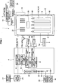
- a solid oxide fuel cell device (SOFC) according to an embodiment of the present invention is furnished with a fuel cell module 2 and an auxiliary unit 4.
- SOFC solid oxide fuel cell device
- a combustion chamber 18 is formed above the aforementioned power generating chamber 10 in the sealed space 8 of the fuel cell module 2. Residual fuel gas and residual oxidant (air) not used in the power generation reaction is combusted in this combustion chamber 18 to produce exhaust gas.
- a reformer 20 for reforming fuel gas is disposed at the top of the combustion chamber 18; the reformer 20 is heated by the heat of residual gas combustion to a temperature at which the reforming reaction can take place.
- An air heat exchanger 22 for receiving the heat of combustion and heating the air is further disposed above this reformer 20.
- the auxiliary unit 4 is furnished with a pure water tank 26 for holding water from a municipal or other water supply source 24 and filtering it into pure water, and a water flow rate regulator unit 28 (a "water pump” or the like driven by a motor) for regulating the flow rate (litter per minute) of water supplied from the reservoir tank.
- the auxiliary unit 4 is further furnished with a gas shutoff valve 32 for shutting off the fuel gas supply from a fuel supply source 30 such as municipal gas or the like, a desulfurizer 36 for desulfurizing the fuel gas, and a fuel gas flow rate regulator unit 38 (a "fuel pump” or the like driven by a motor) for regulating the flow rate (litter per minute) of fuel gas.
- an auxiliary unit 4 is furnished with an electromagnetic valve 42 for shutting off air serving as an oxidant and supplied from an air supply source 40, and a reforming air flow rate regulator unit 44 and generating air flow rate regulator unit 45 ("air blower" or the like driven by a motor) for regulating air flow rate (litter per minute).
- heating means such as a heater for heating the reforming air supply to the reformer 20 or the power generating air supply to the power generating chamber 10 in order to efficiently raise the temperature at startup, nor is there a heating means for separately heating the reformer 20.
- a hot-water producing device 50 supplied with exhaust gas is connected to the fuel cell module 2.
- Municipal water from a water supply source 24 is supplied to this hot-water producing device 50; this water is turned into hot water by the heat of the exhaust gas, and is supplied to a hot water reservoir tank in an external water heater (not shown).
- the fuel cell module 2 is provided with a control box 52 for controlling the supply flow rates of fuel gas and the like.
- an inverter 54 serving as an electrical power extraction unit (electrical power conversion unit) for supplying electrical power generated by the fuel cell module to the outside is connected to the fuel cell module 2.
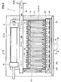
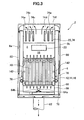
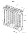
- a fuel cell assembly 12 As shown in Figs. 2 and 3 , a fuel cell assembly 12, a reformer 20, and an air heat exchanger 22 are arranged in sequence starting from the bottom in the sealed space 8 within the fuel cell module 2 housing 6, as described above.
- a fuel gas supply line 64 is connected to the downstream end of the reformer 20; this fuel gas supply line 64 extends downward, then further extends horizontally within a manifold formed under the fuel cell assembly 12.
- Multiple fuel supply holes 64b are formed on the bottom surface of a horizontal portion 64a of the fuel gas supply line 64; reformed fuel gas is supplied into the manifold 66 from these fuel supply holes 64b.
- a lower support plate 68 provided with through holes for supporting the above-described fuel cell stack 14 is attached at the top of the manifold 66, and fuel gas in the manifold 66 is supplied into the fuel cell unit 16.
- An air heat exchanger 22 is provided over the reformer 20.
- the air heat exchanger 22 is furnished with an air concentration chamber 70 on the upstream side and two air distribution chambers 72 on the downstream side; the air concentration chamber 70 and the distribution chambers 72 are connected using six air flow conduits 74.
- three air flow conduits 74 form a set (74a, 74b, 74c, 74d, 74e, 74f); air in the air concentration chamber 70 flows from each set of the air flow conduits 74 to the respective air distribution chambers 72.
- Air flowing in the six air flow conduits 74 of the air heat exchanger 22 is pre-heated by rising combustion exhaust gas from the combustion chamber 18.
- Air guide pipes 76 are connected to each of the respective air distribution chambers 72; these air guide pipes 76 extend downward, communicating at the bottom end side with the lower space in the generating chamber 10, and introducing preheated air into the generating chamber 10.
- an exhaust gas chamber 78 is formed below the manifold 66.
- an exhaust gas conduit 80 extending in the vertical direction is formed on the insides of the front surface 6a and the rear surface 6b which form the faces in the longitudinal direction of the housing 6; the top inside of the exhaust gas conduit 80 communicates with the space in which the air heat exchanger to rule 22 is disposed, and the bottom end side communicates with the exhaust gas chamber 78.
- An exhaust gas discharge pipe 82 is connected at approximately the center of the bottom surface of the exhaust gas chamber 78; the downstream end of the exhaust gas discharge pipe 82 is connected to the above-described hot water producing device 50 shown in Fig. 1 .
- an ignition device 83 for starting the combustion of fuel gas and air is disposed on the combustion chamber 18.
- No heating means such as a burner or the like for separately heating the combustion chamber 18 or the fuel cell unit 16 to support ignition at startup or prevent flameout or blow out is provided on the combustion chamber 18.
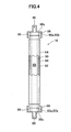
- the fuel cell 84 is a tubular structure extending in the vertical direction, furnished with a cylindrical internal electrode layer 90, on the inside of which is formed a fuel gas flow path 88, a cylindrical external electrode layer 92, and an electrolyte layer 94 between the internal electrode layer 90 and the external electrode layer 92.
- the internal electrode layer 90 is a fuel electrode through which fuel gas passes, and is a (-) pole, while the external electrode layer 92 is an air electrode for contacting the air, and is a (+) pole.
- the internal electrode terminals 86 attached at the top and bottom ends of the fuel cell unit 16 have the same structure, therefore the internal electrode terminal 86 attached at the top end side will be specifically explained.
- the top portion 90a of the inside electrode layer 90 is furnished with an outside perimeter surface 90b and top end surface 90c, exposed to the electrolyte layer 94 and the outside electrode layer 92.
- the inside electrode terminal 86 is connected to the outer perimeter surface 90b of the inside electrode layer 90 through a conductive seal material 96, and is electrically connected to the inside electrode layer 90 by making direct contact with the top end surface 90c of the inside electrode layer 90.
- a fuel gas flow path 98 communicating with fuel gas flow path 88 in the inside electrode layer 90 is formed at the center portion of the inside electrode terminal 86.
- the inside electrode layer 90 is formed, for example, from at least one of a mixture of Ni and zirconia doped with at least one type of rare earth element selected from among Ca, Y, Sc, or the like; or a mixture of Ni and ceria doped with at least one type of rare earth element; or any mixture of Ni with lanthanum gallate doped with at least one element selected from among Sr, Mg, Co, Fe, or Cu.
- the electrolyte layer 94 is formed, for example, from at least one of the following: zirconia doped with at least one type of rare earth element selected from among Y, Sc, or the like; ceria doped with at least one type of selected rare earth element; or lanthanum gallate doped with at least one element selected from among Sr or Mg.
- the outside electrode layer 92 is formed, for example, from at least one of the following: lanthanum manganite doped with at least one element selected from among Sr or Ca; lanthanum ferrite doped with at least one element selected from among Sr, Co, Ni, or Cu; lanthanum cobaltite doped with at least one element selected from among Sr, Fe, Ni, or Cu; Ag, or the like.
- the fuel cell stack 14 As shown in Fig. 5 , the fuel cell stack 14 is furnished with sixteen fuel cell units 16; the top sides and bottom sides of these fuel cell units 16 are respectively supported by a lower support plate 68 and upper support plate 100. Through holes 68a and 100a, through which the inside electrode terminal 86 can penetrate, are provided on the lower support plate 68 and upper support plate 100.
- a current collector 102 and an external terminal 104 are attached to the fuel cell unit 16.
- the current collector 102 is integrally formed by a fuel electrode connecting portion 102a, which is electrically connected to the inside electrode terminal 86 attached to the inside electrode layer 90 serving as the fuel electrode, and by an air electrode connecting portion 102b, which is electrically connected to the entire external perimeter of the outside electrode layer 92 serving as the air electrode.
- the air electrode connecting portion 102b is formed of a vertical portion 102c extending vertically along the surface of the outside electrode layer 92, and multiple horizontal portions 102d extending in the horizontal direction from the vertical portion 102c along the surface of the outside electrode layer 92.
- the fuel electrode connecting portion 102a extends linearly in an upward or downward diagonal direction from the vertical portion 102c of the air electrode connecting portion 102b toward the inside electrode terminals 86 positioned in the upper and lower directions on the fuel cell unit 16.
- inside electrode terminals 86 at the top and bottom ends of the two fuel cell units 16 positioned at the end of the fuel cell stack 14 (at the front and back sides on the left edge in Fig. 5 ) are respectively connected to the external terminals 104.
- These external terminals 104 are connected to the external terminals 104 (not shown) at the ends of the adjacent fuel cell stack 14, and as described above, all of the 160 fuel cell units 16 are connected in series.
- a flammable gas detection sensor 120 detects gas leaks and is attached to the fuel cell module 2 and the auxiliary unit 4.
- the purpose of the flammable gas detection sensor 120 is to detect leakage of CO in the exhaust gas, which is meant to be exhausted to the outside via the exhaust gas conduit 80 and the like, into the external housing (not shown) which covers the fuel cell module 2 and the auxiliary unit 4.
- a water reservoir state detection sensor 124 detects the temperature and amount of hot water in a water heater (not shown).
- An electrical power state detection sensor 126 detects current, voltage, and the like in the inverter 54 and in a distribution panel (not shown).
- a power generating air flow rate detection sensor 128 detects the flow rate of power generating air supplied to the generating chamber 10.
- a reforming air flow rate sensor 130 detects the flow rate of reforming air supplied to the reformer 20.
- a fuel flow rate sensor 132 detects the flow rate of fuel gas supplied to the reformer 20.
- the "Water Flow Amount” column in Fig. 9 shows the flow amount (cc/min) of pure water supplied to the reformer 20 from the water flow regulator unit 28 of the auxiliary unit 4, which is the water supply means for producing pure water and supplying it the reformer 20.
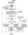
- the "State" column in the "Restart Mode” shown in Fig. 9 shows the respective operating states upon restart from the top row to the bottom row in temporal order; the various operating states are separated into categories abbreviated as "Time of Ignition,” “Restart POX,” “Ignition Prohibition,” “Normal Startup ATR,” and “Normal Startup SR.”
- the reformer 20 temperature band (the "Ignition Prohibited Temperature Band” below) in which "Ignition Prohibition” is executed in the restart mode ignition prohibited control band in the "Restart Mode", is a temperature band greater than or equal to 230°C and less than 500°C, which is higher than the restart POX temperature band W12 of the "Restart Mode".
- the operating state referred to as the "Normal Startup ATR” in the "Restart Mode” shown in Fig. 9 and S11 in Fig. 10 controls startup in the control band (the “Restart Mode ATR control band B13" below) for executing the same ATR as the "Normal Startup ATR” in the “Normal Startup Mode” when the temperature Tr(t) of the reformer 20 is within a temperature band corresponding to the normal startup POX temperature band W2 of the "Normal Startup Mode", and is within a temperature band (the “Restart ATR temperature band W13" below), at or above 500°C and below 600°C, which is in turn higher than the "Restart Mode” ignition prohibition temperature band.
- a major reduction in startup time can be achieved by executing a restart control different from the "Normal Startup POX" in the "Normal Startup Mode” through the active use of residual heat remaining in the fuel cells 84 or the reformer 20.
Landscapes
- Chemical & Material Sciences (AREA)
- Chemical Kinetics & Catalysis (AREA)
- Engineering & Computer Science (AREA)
- Sustainable Development (AREA)
- General Chemical & Material Sciences (AREA)
- Electrochemistry (AREA)
- Sustainable Energy (AREA)
- Life Sciences & Earth Sciences (AREA)
- Manufacturing & Machinery (AREA)
- Organic Chemistry (AREA)
- General Health & Medical Sciences (AREA)
- Inorganic Chemistry (AREA)
- Combustion & Propulsion (AREA)
- Health & Medical Sciences (AREA)
- Fuel Cell (AREA)
Applications Claiming Priority (2)
| Application Number | Priority Date | Filing Date | Title |
|---|---|---|---|
| JP2009087413A JP4863171B2 (ja) | 2009-03-31 | 2009-03-31 | 固体電解質型燃料電池 |
| PCT/JP2010/055906 WO2010114039A1 (ja) | 2009-03-31 | 2010-03-31 | 固体電解質型燃料電池 |
Publications (3)
| Publication Number | Publication Date |
|---|---|
| EP2416418A1 EP2416418A1 (en) | 2012-02-08 |
| EP2416418A4 EP2416418A4 (en) | 2013-01-16 |
| EP2416418B1 true EP2416418B1 (en) | 2015-10-14 |
Family
ID=42828328
Family Applications (1)
| Application Number | Title | Priority Date | Filing Date |
|---|---|---|---|
| EP10758810.5A Not-in-force EP2416418B1 (en) | 2009-03-31 | 2010-03-31 | Solid electrolyte fuel cell |
Country Status (5)
| Country | Link |
|---|---|
| US (1) | US8927162B2 (enExample) |
| EP (1) | EP2416418B1 (enExample) |
| JP (1) | JP4863171B2 (enExample) |
| CN (1) | CN102414894B (enExample) |
| WO (1) | WO2010114039A1 (enExample) |
Families Citing this family (14)
| Publication number | Priority date | Publication date | Assignee | Title |
|---|---|---|---|---|
| JP4761259B2 (ja) * | 2009-05-28 | 2011-08-31 | Toto株式会社 | 固体電解質型燃料電池 |
| JP4707023B2 (ja) * | 2009-09-30 | 2011-06-22 | Toto株式会社 | 固体電解質型燃料電池 |
| CN103119769B (zh) * | 2010-09-30 | 2015-07-29 | Toto株式会社 | 固体氧化物型燃料电池装置 |
| JP5561655B2 (ja) | 2010-09-30 | 2014-07-30 | Toto株式会社 | 固体酸化物形燃料電池装置 |
| WO2012165516A1 (ja) * | 2011-05-30 | 2012-12-06 | 京セラ株式会社 | 燃料電池装置 |
| JP6145683B2 (ja) * | 2011-12-14 | 2017-06-14 | パナソニックIpマネジメント株式会社 | 燃料電池発電システム |
| JP5902581B2 (ja) * | 2012-08-02 | 2016-04-13 | 本田技研工業株式会社 | 燃料電池システム及びその制御方法 |
| JP6183775B2 (ja) * | 2013-03-25 | 2017-08-23 | Toto株式会社 | 固体酸化物型燃料電池システム |
| JP6183774B2 (ja) * | 2013-03-25 | 2017-08-23 | Toto株式会社 | 固体酸化物型燃料電池システム |
| JP2015127998A (ja) * | 2013-12-27 | 2015-07-09 | Toto株式会社 | 固体酸化物型燃料電池システム |
| JP2015127999A (ja) * | 2013-12-27 | 2015-07-09 | Toto株式会社 | 固体酸化物型燃料電池システム |
| DE102014218726A1 (de) * | 2014-09-18 | 2016-04-07 | Robert Bosch Gmbh | Brennstoffzellenvorrichtung mit verbessertem Anodengasprozessor |
| KR102587217B1 (ko) * | 2016-05-24 | 2023-10-12 | 주식회사 미코파워 | 연료전지 시스템 |
| US10840528B2 (en) | 2016-12-19 | 2020-11-17 | Cummins Enterprise Llc | Method and apparatus for detecting damage in fuel cell stacks, and adjusting operational characteristics in fuel cell systems |
Family Cites Families (10)
| Publication number | Priority date | Publication date | Assignee | Title |
|---|---|---|---|---|
| JP2003095611A (ja) * | 2001-09-19 | 2003-04-03 | Toyota Motor Corp | 水素生成装置の起動方法 |
| JP4369685B2 (ja) * | 2003-02-25 | 2009-11-25 | 京セラ株式会社 | 燃料電池の運転方法 |
| JP4232528B2 (ja) * | 2003-05-13 | 2009-03-04 | 住友ベークライト株式会社 | 合わせガラス |
| JP2004338975A (ja) * | 2003-05-13 | 2004-12-02 | Mitsubishi Kakoki Kaisha Ltd | 水素製造装置の起動方法 |
| JP2006086016A (ja) * | 2004-09-16 | 2006-03-30 | Kyocera Corp | 固体酸化物形燃料電池の運転方法 |
| JP4767543B2 (ja) * | 2005-01-07 | 2011-09-07 | Jx日鉱日石エネルギー株式会社 | 固体酸化物形燃料電池システムの起動方法 |
| JP2006269196A (ja) | 2005-03-23 | 2006-10-05 | Nissan Motor Co Ltd | 燃料電池システム |
| JP2007311072A (ja) | 2006-05-16 | 2007-11-29 | Acumentrics Corp | 燃料電池システム及びその運転方法 |
| JP2008243597A (ja) * | 2007-03-27 | 2008-10-09 | Kyocera Corp | 燃料電池装置 |
| US20110053017A1 (en) * | 2007-08-29 | 2011-03-03 | Kyocera Corporation | Fuel Cell Apparatus |
-
2009
- 2009-03-31 JP JP2009087413A patent/JP4863171B2/ja not_active Expired - Fee Related
-
2010
- 2010-03-31 US US13/262,014 patent/US8927162B2/en not_active Expired - Fee Related
- 2010-03-31 WO PCT/JP2010/055906 patent/WO2010114039A1/ja not_active Ceased
- 2010-03-31 CN CN201080019134.8A patent/CN102414894B/zh not_active Expired - Fee Related
- 2010-03-31 EP EP10758810.5A patent/EP2416418B1/en not_active Not-in-force
Also Published As
| Publication number | Publication date |
|---|---|
| US8927162B2 (en) | 2015-01-06 |
| WO2010114039A1 (ja) | 2010-10-07 |
| EP2416418A1 (en) | 2012-02-08 |
| EP2416418A4 (en) | 2013-01-16 |
| CN102414894B (zh) | 2015-09-16 |
| JP4863171B2 (ja) | 2012-01-25 |
| US20120028143A1 (en) | 2012-02-02 |
| CN102414894A (zh) | 2012-04-11 |
| JP2010238623A (ja) | 2010-10-21 |
Similar Documents
| Publication | Publication Date | Title |
|---|---|---|
| EP2416418B1 (en) | Solid electrolyte fuel cell | |
| US8431274B2 (en) | Solid oxide fuel cell device | |
| US8795910B2 (en) | Solid oxide fuel cell device | |
| EP2256850B1 (en) | Solid oxide fuel cell device | |
| EP2256849B1 (en) | Solid oxide fuel cell device | |
| CN102035004B (zh) | 固体电解质型燃料电池 | |
| US9236625B2 (en) | Solid oxide fuel cell system | |
| EP2624346A1 (en) | Fuel cell device | |
| EP2624349B1 (en) | Solid oxide fuel cell device | |
| EP2256848B1 (en) | Solid oxide fuel cell device | |
| EP2306573B1 (en) | Solid oxide fuel cell device | |
| EP2306574A1 (en) | Solid oxide fuel cell device | |
| EP2624348B1 (en) | Solid oxide fuel cell device | |
| EP2624347B1 (en) | Solid oxide fuel cell | |
| JP5505872B2 (ja) | 固体電解質型燃料電池 | |
| JP2013191585A (ja) | 固体電解質型燃料電池 |
Legal Events
| Date | Code | Title | Description |
|---|---|---|---|
| PUAI | Public reference made under article 153(3) epc to a published international application that has entered the european phase |
Free format text: ORIGINAL CODE: 0009012 |
|
| 17P | Request for examination filed |
Effective date: 20111006 |
|
| AK | Designated contracting states |
Kind code of ref document: A1 Designated state(s): AT BE BG CH CY CZ DE DK EE ES FI FR GB GR HR HU IE IS IT LI LT LU LV MC MK MT NL NO PL PT RO SE SI SK SM TR |
|
| DAX | Request for extension of the european patent (deleted) | ||
| RAP1 | Party data changed (applicant data changed or rights of an application transferred) |
Owner name: TOTO LTD. |
|
| A4 | Supplementary search report drawn up and despatched |
Effective date: 20121218 |
|
| RIC1 | Information provided on ipc code assigned before grant |
Ipc: H01M 8/12 20060101ALI20121212BHEP Ipc: H01M 8/04 20060101AFI20121212BHEP Ipc: C01B 3/38 20060101ALI20121212BHEP Ipc: H01M 8/06 20060101ALI20121212BHEP |
|
| 17Q | First examination report despatched |
Effective date: 20131119 |
|
| GRAP | Despatch of communication of intention to grant a patent |
Free format text: ORIGINAL CODE: EPIDOSNIGR1 |
|
| INTG | Intention to grant announced |
Effective date: 20150508 |
|
| GRAS | Grant fee paid |
Free format text: ORIGINAL CODE: EPIDOSNIGR3 |
|
| GRAA | (expected) grant |
Free format text: ORIGINAL CODE: 0009210 |
|
| AK | Designated contracting states |
Kind code of ref document: B1 Designated state(s): AT BE BG CH CY CZ DE DK EE ES FI FR GB GR HR HU IE IS IT LI LT LU LV MC MK MT NL NO PL PT RO SE SI SK SM TR |
|
| REG | Reference to a national code |
Ref country code: GB Ref legal event code: FG4D |
|
| REG | Reference to a national code |
Ref country code: AT Ref legal event code: REF Ref document number: 755707 Country of ref document: AT Kind code of ref document: T Effective date: 20151015 Ref country code: CH Ref legal event code: EP |
|
| REG | Reference to a national code |
Ref country code: IE Ref legal event code: FG4D |
|
| REG | Reference to a national code |
Ref country code: DE Ref legal event code: R096 Ref document number: 602010028263 Country of ref document: DE |
|
| REG | Reference to a national code |
Ref country code: NL Ref legal event code: MP Effective date: 20151014 |
|
| REG | Reference to a national code |
Ref country code: LT Ref legal event code: MG4D |
|
| REG | Reference to a national code |
Ref country code: AT Ref legal event code: MK05 Ref document number: 755707 Country of ref document: AT Kind code of ref document: T Effective date: 20151014 |
|
| PG25 | Lapsed in a contracting state [announced via postgrant information from national office to epo] |
Ref country code: NO Free format text: LAPSE BECAUSE OF FAILURE TO SUBMIT A TRANSLATION OF THE DESCRIPTION OR TO PAY THE FEE WITHIN THE PRESCRIBED TIME-LIMIT Effective date: 20160114 Ref country code: LT Free format text: LAPSE BECAUSE OF FAILURE TO SUBMIT A TRANSLATION OF THE DESCRIPTION OR TO PAY THE FEE WITHIN THE PRESCRIBED TIME-LIMIT Effective date: 20151014 Ref country code: ES Free format text: LAPSE BECAUSE OF FAILURE TO SUBMIT A TRANSLATION OF THE DESCRIPTION OR TO PAY THE FEE WITHIN THE PRESCRIBED TIME-LIMIT Effective date: 20151014 Ref country code: HR Free format text: LAPSE BECAUSE OF FAILURE TO SUBMIT A TRANSLATION OF THE DESCRIPTION OR TO PAY THE FEE WITHIN THE PRESCRIBED TIME-LIMIT Effective date: 20151014 Ref country code: NL Free format text: LAPSE BECAUSE OF FAILURE TO SUBMIT A TRANSLATION OF THE DESCRIPTION OR TO PAY THE FEE WITHIN THE PRESCRIBED TIME-LIMIT Effective date: 20151014 Ref country code: IT Free format text: LAPSE BECAUSE OF FAILURE TO SUBMIT A TRANSLATION OF THE DESCRIPTION OR TO PAY THE FEE WITHIN THE PRESCRIBED TIME-LIMIT Effective date: 20151014 Ref country code: IS Free format text: LAPSE BECAUSE OF FAILURE TO SUBMIT A TRANSLATION OF THE DESCRIPTION OR TO PAY THE FEE WITHIN THE PRESCRIBED TIME-LIMIT Effective date: 20160214 |
|
| PG25 | Lapsed in a contracting state [announced via postgrant information from national office to epo] |
Ref country code: GR Free format text: LAPSE BECAUSE OF FAILURE TO SUBMIT A TRANSLATION OF THE DESCRIPTION OR TO PAY THE FEE WITHIN THE PRESCRIBED TIME-LIMIT Effective date: 20160115 Ref country code: LV Free format text: LAPSE BECAUSE OF FAILURE TO SUBMIT A TRANSLATION OF THE DESCRIPTION OR TO PAY THE FEE WITHIN THE PRESCRIBED TIME-LIMIT Effective date: 20151014 Ref country code: SE Free format text: LAPSE BECAUSE OF FAILURE TO SUBMIT A TRANSLATION OF THE DESCRIPTION OR TO PAY THE FEE WITHIN THE PRESCRIBED TIME-LIMIT Effective date: 20151014 Ref country code: PT Free format text: LAPSE BECAUSE OF FAILURE TO SUBMIT A TRANSLATION OF THE DESCRIPTION OR TO PAY THE FEE WITHIN THE PRESCRIBED TIME-LIMIT Effective date: 20160215 Ref country code: FI Free format text: LAPSE BECAUSE OF FAILURE TO SUBMIT A TRANSLATION OF THE DESCRIPTION OR TO PAY THE FEE WITHIN THE PRESCRIBED TIME-LIMIT Effective date: 20151014 Ref country code: PL Free format text: LAPSE BECAUSE OF FAILURE TO SUBMIT A TRANSLATION OF THE DESCRIPTION OR TO PAY THE FEE WITHIN THE PRESCRIBED TIME-LIMIT Effective date: 20151014 Ref country code: AT Free format text: LAPSE BECAUSE OF FAILURE TO SUBMIT A TRANSLATION OF THE DESCRIPTION OR TO PAY THE FEE WITHIN THE PRESCRIBED TIME-LIMIT Effective date: 20151014 |
|
| REG | Reference to a national code |
Ref country code: DE Ref legal event code: R097 Ref document number: 602010028263 Country of ref document: DE |
|
| PG25 | Lapsed in a contracting state [announced via postgrant information from national office to epo] |
Ref country code: CZ Free format text: LAPSE BECAUSE OF FAILURE TO SUBMIT A TRANSLATION OF THE DESCRIPTION OR TO PAY THE FEE WITHIN THE PRESCRIBED TIME-LIMIT Effective date: 20151014 |
|
| PLBE | No opposition filed within time limit |
Free format text: ORIGINAL CODE: 0009261 |
|
| STAA | Information on the status of an ep patent application or granted ep patent |
Free format text: STATUS: NO OPPOSITION FILED WITHIN TIME LIMIT |
|
| PG25 | Lapsed in a contracting state [announced via postgrant information from national office to epo] |
Ref country code: DK Free format text: LAPSE BECAUSE OF FAILURE TO SUBMIT A TRANSLATION OF THE DESCRIPTION OR TO PAY THE FEE WITHIN THE PRESCRIBED TIME-LIMIT Effective date: 20151014 Ref country code: RO Free format text: LAPSE BECAUSE OF FAILURE TO SUBMIT A TRANSLATION OF THE DESCRIPTION OR TO PAY THE FEE WITHIN THE PRESCRIBED TIME-LIMIT Effective date: 20151014 Ref country code: BE Free format text: LAPSE BECAUSE OF NON-PAYMENT OF DUE FEES Effective date: 20160331 Ref country code: SK Free format text: LAPSE BECAUSE OF FAILURE TO SUBMIT A TRANSLATION OF THE DESCRIPTION OR TO PAY THE FEE WITHIN THE PRESCRIBED TIME-LIMIT Effective date: 20151014 Ref country code: SM Free format text: LAPSE BECAUSE OF FAILURE TO SUBMIT A TRANSLATION OF THE DESCRIPTION OR TO PAY THE FEE WITHIN THE PRESCRIBED TIME-LIMIT Effective date: 20151014 Ref country code: EE Free format text: LAPSE BECAUSE OF FAILURE TO SUBMIT A TRANSLATION OF THE DESCRIPTION OR TO PAY THE FEE WITHIN THE PRESCRIBED TIME-LIMIT Effective date: 20151014 |
|
| 26N | No opposition filed |
Effective date: 20160715 |
|
| PG25 | Lapsed in a contracting state [announced via postgrant information from national office to epo] |
Ref country code: LU Free format text: LAPSE BECAUSE OF FAILURE TO SUBMIT A TRANSLATION OF THE DESCRIPTION OR TO PAY THE FEE WITHIN THE PRESCRIBED TIME-LIMIT Effective date: 20160331 Ref country code: MC Free format text: LAPSE BECAUSE OF FAILURE TO SUBMIT A TRANSLATION OF THE DESCRIPTION OR TO PAY THE FEE WITHIN THE PRESCRIBED TIME-LIMIT Effective date: 20151014 |
|
| REG | Reference to a national code |
Ref country code: CH Ref legal event code: PL |
|
| GBPC | Gb: european patent ceased through non-payment of renewal fee |
Effective date: 20160331 |
|
| PG25 | Lapsed in a contracting state [announced via postgrant information from national office to epo] |
Ref country code: SI Free format text: LAPSE BECAUSE OF FAILURE TO SUBMIT A TRANSLATION OF THE DESCRIPTION OR TO PAY THE FEE WITHIN THE PRESCRIBED TIME-LIMIT Effective date: 20151014 |
|
| REG | Reference to a national code |
Ref country code: IE Ref legal event code: MM4A |
|
| PG25 | Lapsed in a contracting state [announced via postgrant information from national office to epo] |
Ref country code: BE Free format text: LAPSE BECAUSE OF FAILURE TO SUBMIT A TRANSLATION OF THE DESCRIPTION OR TO PAY THE FEE WITHIN THE PRESCRIBED TIME-LIMIT Effective date: 20151014 |
|
| REG | Reference to a national code |
Ref country code: FR Ref legal event code: ST Effective date: 20161130 |
|
| PG25 | Lapsed in a contracting state [announced via postgrant information from national office to epo] |
Ref country code: GB Free format text: LAPSE BECAUSE OF NON-PAYMENT OF DUE FEES Effective date: 20160331 Ref country code: LI Free format text: LAPSE BECAUSE OF NON-PAYMENT OF DUE FEES Effective date: 20160331 Ref country code: FR Free format text: LAPSE BECAUSE OF NON-PAYMENT OF DUE FEES Effective date: 20160331 Ref country code: IE Free format text: LAPSE BECAUSE OF NON-PAYMENT OF DUE FEES Effective date: 20160331 Ref country code: CH Free format text: LAPSE BECAUSE OF NON-PAYMENT OF DUE FEES Effective date: 20160331 |
|
| PG25 | Lapsed in a contracting state [announced via postgrant information from national office to epo] |
Ref country code: MT Free format text: LAPSE BECAUSE OF FAILURE TO SUBMIT A TRANSLATION OF THE DESCRIPTION OR TO PAY THE FEE WITHIN THE PRESCRIBED TIME-LIMIT Effective date: 20151014 |
|
| PGFP | Annual fee paid to national office [announced via postgrant information from national office to epo] |
Ref country code: DE Payment date: 20180320 Year of fee payment: 9 |
|
| PG25 | Lapsed in a contracting state [announced via postgrant information from national office to epo] |
Ref country code: HU Free format text: LAPSE BECAUSE OF FAILURE TO SUBMIT A TRANSLATION OF THE DESCRIPTION OR TO PAY THE FEE WITHIN THE PRESCRIBED TIME-LIMIT; INVALID AB INITIO Effective date: 20100331 Ref country code: CY Free format text: LAPSE BECAUSE OF FAILURE TO SUBMIT A TRANSLATION OF THE DESCRIPTION OR TO PAY THE FEE WITHIN THE PRESCRIBED TIME-LIMIT Effective date: 20151014 |
|
| PG25 | Lapsed in a contracting state [announced via postgrant information from national office to epo] |
Ref country code: MK Free format text: LAPSE BECAUSE OF FAILURE TO SUBMIT A TRANSLATION OF THE DESCRIPTION OR TO PAY THE FEE WITHIN THE PRESCRIBED TIME-LIMIT Effective date: 20151014 Ref country code: TR Free format text: LAPSE BECAUSE OF FAILURE TO SUBMIT A TRANSLATION OF THE DESCRIPTION OR TO PAY THE FEE WITHIN THE PRESCRIBED TIME-LIMIT Effective date: 20151014 |
|
| PG25 | Lapsed in a contracting state [announced via postgrant information from national office to epo] |
Ref country code: BG Free format text: LAPSE BECAUSE OF FAILURE TO SUBMIT A TRANSLATION OF THE DESCRIPTION OR TO PAY THE FEE WITHIN THE PRESCRIBED TIME-LIMIT Effective date: 20151014 |
|
| REG | Reference to a national code |
Ref country code: DE Ref legal event code: R119 Ref document number: 602010028263 Country of ref document: DE |
|
| PG25 | Lapsed in a contracting state [announced via postgrant information from national office to epo] |
Ref country code: DE Free format text: LAPSE BECAUSE OF NON-PAYMENT OF DUE FEES Effective date: 20191001 |