WO2010113591A1 - 吸収性物品 - Google Patents
吸収性物品 Download PDFInfo
- Publication number
- WO2010113591A1 WO2010113591A1 PCT/JP2010/053593 JP2010053593W WO2010113591A1 WO 2010113591 A1 WO2010113591 A1 WO 2010113591A1 JP 2010053593 W JP2010053593 W JP 2010053593W WO 2010113591 A1 WO2010113591 A1 WO 2010113591A1
- Authority
- WO
- WIPO (PCT)
- Prior art keywords
- wing forming
- wing
- forming member
- sheet
- absorbent
- Prior art date
- Legal status (The legal status is an assumption and is not a legal conclusion. Google has not performed a legal analysis and makes no representation as to the accuracy of the status listed.)
- Ceased
Links
Images





Classifications
-
- A—HUMAN NECESSITIES
- A61—MEDICAL OR VETERINARY SCIENCE; HYGIENE
- A61F—FILTERS IMPLANTABLE INTO BLOOD VESSELS; PROSTHESES; DEVICES PROVIDING PATENCY TO, OR PREVENTING COLLAPSING OF, TUBULAR STRUCTURES OF THE BODY, e.g. STENTS; ORTHOPAEDIC, NURSING OR CONTRACEPTIVE DEVICES; FOMENTATION; TREATMENT OR PROTECTION OF EYES OR EARS; BANDAGES, DRESSINGS OR ABSORBENT PADS; FIRST-AID KITS
- A61F13/00—Bandages or dressings; Absorbent pads
- A61F13/15—Absorbent pads, e.g. sanitary towels, swabs or tampons for external or internal application to the body; Supporting or fastening means therefor; Tampon applicators
- A61F13/56—Supporting or fastening means
- A61F13/5605—Supporting or fastening means specially adapted for sanitary napkins or the like
- A61F13/5616—Supporting or fastening means specially adapted for sanitary napkins or the like using flaps, e.g. adhesive, for attachment to the undergarment
Definitions
- the present invention relates to an absorbent article.
- An absorptive article which joins a pair of wings to the surface of a top sheet, and fixes an absorptive body to clothing like underwear by these wings is known (refer to patent documents 1).
- the wing since the wing is only joined to the top sheet, the wing may be detached from the top sheet due to a user's movement or the like. If the wing is detached from the top sheet, the absorbent main body cannot be securely fixed to the clothing, so that the absorbent main body may be twisted or removed from the proper position. As a result, the liquid to be absorbed such as menstrual blood and urine may leak.
- a joining location will become hard and there exists a possibility that the usability
- an absorption body comprising an absorption body including a liquid-permeable top sheet, a liquid-impermeable back sheet, and an absorber disposed between the top sheet and the back sheet.
- a wing forming body that forms a pair of wings that extend outward beyond the left and right side edges of the absorbent body, the wing forming body gripped between the top sheet and the back sheet,
- the wing forming body includes a single wing forming member or a plurality of wing forming members, and the single wing forming member or the wing forming member is composed of two intermediate sheets superposed on each other, and between the intermediate sheets of at least one wing forming member.
- An absorbent article is provided in which the absorbent body is retained.
- the absorbent body can be securely fixed to clothing without deteriorating the feeling of use of the absorbent article.
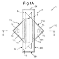
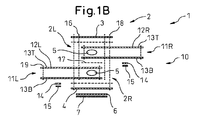
- FIG. 1A and 1B are a front view of a sanitary napkin and a schematic cross-sectional view taken along line BB.
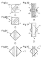
- 2A to 2G are schematic views for explaining a method for producing a sanitary napkin.
- FIG. 3 is a schematic longitudinal sectional view of a sanitary napkin for explaining a use state.
- FIG. 4 is a front view of a sanitary napkin showing a modified example of the absorbent main body.
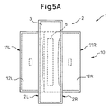
- 5A and 5B are a front view and a schematic cross-sectional view of a sanitary napkin showing various modifications of the wing-forming body.
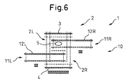
- 6 is a schematic cross-sectional view of a sanitary napkin showing various modifications of the wing former.
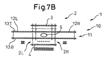
- 7A and 7B are a front view and a schematic cross-sectional view of a sanitary napkin showing various modified examples of the wing formed body.
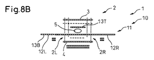
- 8A to 8C are schematic cross-sectional views of a sanitary napkin showing various modifications of the wing former.
- a sanitary napkin (hereinafter also simply referred to as “napkin”) 1 according to an embodiment of the present invention includes an absorbent body 2.
- the absorbent main body 2 includes a liquid-permeable top sheet 3, a liquid-impermeable back sheet 4, and a liquid-retaining absorbent 5 disposed between the top sheet 3 and the back sheet 4. .
- the top sheet 3 and the back sheet 4 have a rectangular shape having almost the same size.
- an adhesive portion 6 for fixing the absorbent main body 2 to the underwear is formed on the surface of the back sheet 4 that is directed to clothing such as underwear during use, and this adhesive portion 6 is covered with a protective sheet 7.
- 1A and 1B, 2F, 2B, 2L, and 2R indicate the front edge, the rear edge, the left edge, and the right edge of the napkin 1 or the absorbent body 2, respectively.
- the front, rear, left and right in this case correspond to the front, back, left and right of the user's body in use.
- the napkin 1 further includes a wing forming body 10 held between the top sheet 3 and the back sheet 4. In the example shown in FIGS.
- the wing forming body 10 includes a pair of wing forming members, that is, a left wing forming member 11L and a right wing forming member 11R.
- the left wing forming member 11L forms a triangular left wing 12L that extends outward beyond the left edge 2L of the absorbent body 2, and the right wing forming member 11R extends outward beyond the right edge 2R of the absorbent body 2.
- a triangular right wing 12R is formed.
- the left wing forming member 11L and the right wing forming member 11R are each composed of two intermediate sheets 13T and 13B that are overlapped with each other.
- the absorber 5 is held between the intermediate sheets 13T and 13B, and the left wing forming member 11L and the right wing forming member 11R are overlapped so that the absorbers 5 overlap each other in the vertical direction.
- Each of the left wing forming member 11L and the right wing forming member 11R has a triangular shape, particularly a right isosceles triangular shape.
- the left wing is positioned so that one corner, that is, the apex angle, is located outside the top sheet 3 and the back sheet 4, and the other two corners, ie, the bottom angle, are located between the top sheet 3 and the back sheet 4.
- the forming member 11L and the right wing forming member 11R are disposed between the top sheet 3 and the back sheet 4, respectively.
- the absorber 5 is arranged in a band shape along one side, that is, the bottom side.
- Adhesive portions 14 for fixing the left wing forming member 11L and the right wing forming member 11R to the underwear are respectively formed on the back surface or the intermediate sheet 13B of the left wing forming member 11L and the right wing forming member 11R.
- top sheet 3 is formed with a pair of embossed regions or hinge regions 16 extending in an arc shape on both sides of the absorbent body 5.
- reference numeral 17 denotes a hot melt adhesive that joins the left wing forming member 11L and the right wing forming member 11R, the top sheet 3 and the wing forming body 10, and the back sheet 4 and the wing forming body 10, respectively.
- reference numeral 18 denotes a joining region where the top sheet 3, the back sheet 4, and the wing forming body 10 are joined together
- 19 denotes a joining region where the intermediate sheets 13T and 13B are joined together.
- This sheet blank 13B ′ finally forms a pair of intermediate sheets 13B.
- a sheet blank 13T ′ having the same size and shape as the sheet blank 13B ′ is overlaid on the sheet blank 13B ′.
- This sheet blank 13T ′ finally forms an intermediate sheet 13T.
- the intermediate body 20 holding the absorber 5 is formed.
- the joining region 19 extends along the four sides and the diagonal D of the sheet blanks 13T ′ and 13B ′ to form two triangles. Therefore, the absorber 5 is prevented from dripping from the intermediate body 5.
- the intermediate 20 is rotated by 45 degrees.
- the intermediate body 20 is cut into two equal parts along the diagonal line D to form the left wing forming member 11L and the right wing forming member 11R.
- the left wing forming member 11L and the right wing forming member 11R are overlapped so that the absorbent bodies 5 overlap each other.
- the hot melt adhesive 17 (see FIG. 1B) is applied spirally or solidly in the overlapping region, and thus the left wing forming member 11L and the right wing forming member 11R are joined to each other.
- the wing forming body 10 is formed.
- the wing forming body 10 is disposed between the top sheet 3 and the back sheet 4.
- the hot melt adhesive 17 is applied between the top sheet 3 and the wing forming body 10 and between the back sheet 4 and the wing forming body 10 in a spiral shape or a solid coating. 3 and the wing forming body 10 are joined together, and the back sheet 4 and the wing forming body 10 are joined together.
- heat sealing is applied to the periphery of the top sheet 3 and the back sheet 4, so that the top sheet 3, the back sheet 4, and the wing forming body 10 are joined to each other by the joining region 18.
- the adhesive portion 6 is formed on the back sheet 4, and the adhesive portion 14 is formed on the back surface of the left wing 12L and the right wing 12R or the intermediate sheet 13B.
- the adhesive portions 6 and 14 are formed by first applying a hot melt adhesive onto a release paper or a release film and then transferring it to the back sheet 4.
- the adhesive portion 14 is formed by directly applying a hot melt adhesive onto the intermediate sheet 13B.
- the top sheet 3 is composed of an air-through nonwoven fabric.
- the top sheet 3 can be composed of, for example, a perforated or non-porous nonwoven fabric or a porous plastic sheet.
- the back sheet 4 is made of a polyethylene film. However, the backsheet 4 is sandwiched between, for example, a hydrophobic nonwoven fabric, a water-impermeable plastic film, a laminate sheet of a nonwoven fabric and a water-impermeable plastic film, a highly water-resistant meltblown nonwoven fabric, and a meltblown nonwoven fabric with a strong spunbond nonwoven fabric. It can be composed of SMS nonwoven fabric.
- the absorbent body 5 is made of, for example, a highly absorbent polymer entangled with fluffy pulp or an airlaid nonwoven fabric.
- the fluffy pulp is composed of, for example, artificial cellulose fibers such as chemical pulp, cellulose fiber, rayon, and acetate
- the airlaid nonwoven fabric is composed of, for example, a nonwoven fabric in which pulp and synthetic fiber are thermally fused or fixed with a binder.
- the superabsorbent polymer is composed of, for example, a starch-based, acrylic acid-based, or amino acid-based particulate or fibrous polymer. Note that pulp can be omitted. If it does in this way, the absorption main body 2 will become soft and a usability
- the front side intermediate sheet 13T is preferably a commonly used nonwoven fabric that retains hydrophilicity, and is composed of, for example, an air-through nonwoven fabric, a heat roll nonwoven fabric, a spunbond nonwoven fabric, or a melt blown nonwoven fabric. Since the intermediate sheet 13T can come into contact with the user's body, an air-through nonwoven fabric is particularly preferable from the viewpoint of texture and touch.
- the basis weight is texture and feel in terms of liquid-permeable, preferably 100 g / m 2 from 15 g / m 2.
- the back side intermediate sheet 13B is also preferably a nonwoven fabric that is generally used and has hydrophilicity, and is composed of, for example, an air-through nonwoven fabric, a heat roll nonwoven fabric, a spunbond nonwoven fabric, or a melt blown nonwoven fabric.
- a nonwoven fabric that is generally used and has hydrophilicity
- an SMS nonwoven fabric in which a meltblown nonwoven fabric or a meltblown nonwoven fabric is sandwiched between strong spunbond nonwoven fabrics is preferable. This is because the SMS nonwoven fabric has high smoothness and is suitable for the above-described adhesive portion 14 to be applied.
- the basis weight is preferably 10 g / m 2 or less and at most 20 g / m 2 in consideration of liquid permeability and removal of the superabsorbent polymer.
- the adhesive portions 6 and 14 are hot melts such as styrene-isoprene-styrene block copolymer (SIS), styrene-butadiene-styrene block copolymer (SBS), styrene-ethylene-butylene-ethylene copolymer (SEBS), etc. Consists of an adhesive.
- SIS styrene-isoprene-styrene block copolymer
- SBS styrene-butadiene-styrene block copolymer
- SEBS styrene-ethylene-butylene-ethylene copolymer
- the protective sheets 15 of the left wing 12L and the right wing 12R are removed, and the left wing 12L and the right wing 12R are fixed to the underwear via the respective adhesive portions 14. That is, as shown in FIG. 3, the left wing 12 ⁇ / b> L and the right wing 12 ⁇ / b> R are respectively fixed to the outer surface of the underwear U below the absorption body 2. In this way, the left wing 12L and the right wing 12R are fixed to the underwear U, and thus the absorbent main body 2 is fixed to the underwear U. In this case, the left wing 12 ⁇ / b> L and the right wing 12 ⁇ / b> R sandwich the underwear U between the absorbent body 2.
- the absorption main body 2 can be reliably fixed to the underwear U, and therefore leakage of the liquid to be absorbed can be suppressed. Moreover, the user's anxiety about leakage can be eliminated.
- the left wing forming member 11L and the right wing forming member 11R are held between the top sheet 3 and the back sheet 4, so that the left wing forming member 11L is not impaired. And the right wing forming member 11R can be reliably joined to the absorbent main body 2.
- top sheet 3 and the back sheet 4 are rectangular, and the intermediate sheets 13T and 13B are formed by dividing the rectangular sheet blanks 13T ′ and 13B ′ into two, trim loss can be reduced to zero. Furthermore, since the left wing 12L and the right wing 12R have a triangular shape, the shape is similar to that of the conventional wing, and there is little discomfort for the user. By the way, in the conventional general absorbent article with a wing, a wing is formed from the top sheet and back sheet which extend beyond the left-right side edge of an absorption main body. However, since the polyethylene sheet generally used for the back sheet has low heat resistance, the hot melt adhesive cannot be directly applied.
- the hot melt adhesive is first applied onto the release paper or release film, and then transferred to the back sheet to form an adhesive portion.
- silicone is present on the surface of the release paper or release film, and if this silicone remains on the surface of the adhesive part, the adhesion strength of the adhesive part to clothing may be reduced.
- the adhesion part 14 is formed in the intermediate sheet 13B comprised, for example from SMS nonwoven fabric, the adhesion part 14 can be formed without using a release paper or a release film. it can. Therefore, high fixing strength of the left wing 12L and the right wing 12R can be ensured.
- the absorbent article manufacturing method of the embodiment according to the present invention has almost the same number of steps as that of the manufacturing process of a general absorbent article with a wing, and does not need to add a complicated device.
- the top sheet 3 and the back sheet 4 have a rectangular shape, and thus the absorbent body 2 has a rectangular shape.
- the front end edge 2F and the rear end edge 2B of the absorbent body 2 may be cut so as to be curved. In this case, trim or cutting waste is generated, but trim loss can be greatly reduced.
- the left wing forming member 11L and the right wing forming member 11R have a triangular shape, and the left wing 12L and the right wing 12R also have a triangular shape.
- the left wing forming member 11L and the right wing forming member 11R may have a rectangular shape, particularly a square shape, and the left wing 12L and the right wing 12R may also have a rectangular shape. . In this way, it is not necessary to rotate the intermediate body 20 (see FIG. 2C).
- FIG. 5A and 5B the left wing forming member 11L and the right wing forming member 11R may have a rectangular shape, particularly a square shape, and the left wing 12L and the right wing 12R may also have a rectangular shape. . In this way, it is not necessary to rotate the intermediate body 20 (see FIG. 2C).
- FIG. 1C it is not necessary to rotate the intermediate body 20 (see FIG. 2C).
- the right wing forming member 11 ⁇ / b> R may hold the absorber 5 without the left wing forming member 11 ⁇ / b> L holding the absorber 5. That is, generally speaking, the absorber 5 is held between one or both of the intermediate wings 13T and 13B of the left wing forming member 11L and the right wing forming member 11R.
- the wing forming body 10 may include a single wing forming member 11. In this case, the single wing forming member 11 forms a pair of wings 12L and 12R that extend outward beyond the left and right side edges 2L and 2R of the absorbent main body 2, respectively.
- the single wing forming member 11 is composed of two intermediate sheets 13T and 13B, and the absorber 5 is held between the intermediate sheets 13T and 13B. Therefore, in general terms, the wing forming body 10 includes a single or a plurality of wing forming members, and is composed of two intermediate sheets in which the single or a plurality of wing forming members are superposed on each other, and includes at least one wing forming member. The absorber 5 is held between the intermediate sheets of the wing forming member.
- the left wing 12L and the right wing 12R are triangular. However, as shown in FIGS. 5A and 5B, the left wing 12L and the right wing 12R may be rectangular.
- the left wing 12L and the right wing 12R are composed of two intermediate sheets 13T and 13B overlapped with each other.
- the left wing 12L and the right wing 12R may be configured by a single intermediate sheet 13T, 13B. That is, in the example shown in FIG. 8A, the left wing 12L is composed only of the intermediate sheet 13B on the back side of the left wing forming member 11L, and the right wing 12R is composed only of the intermediate sheet 13B on the back side of the right wing forming member 11R. .
- the intermediate sheet 13T on the front side does not extend outward beyond the left and right side edges 2L, 2R of the absorbent main body 2, and the size necessary for holding the absorbent body 5 is sufficient.
- the front side intermediate sheet 13T does not extend outward beyond the left and right side edges 2L and 2R, and the left wing 12L and the right wing 12R are configured by only the back side intermediate sheet 13B.
- the left wing 12L is composed of an intermediate seat 13B
- the right wing 12R is composed of an intermediate seat 13T.
- the intermediate sheet 13B extends outward beyond the left edge 2L without exceeding the right edge 2R.
- the front intermediate sheet 13T extends outward beyond the right edge 2R without exceeding the left end 2L.
- the intermediate sheets 13T and 13B overlap each other between the top sheet 3 and the back sheet 4, and the absorber 5 is held in this overlapping region.
Landscapes
- Health & Medical Sciences (AREA)
- Epidemiology (AREA)
- Engineering & Computer Science (AREA)
- Biomedical Technology (AREA)
- Heart & Thoracic Surgery (AREA)
- Vascular Medicine (AREA)
- Life Sciences & Earth Sciences (AREA)
- Animal Behavior & Ethology (AREA)
- General Health & Medical Sciences (AREA)
- Public Health (AREA)
- Veterinary Medicine (AREA)
- Absorbent Articles And Supports Therefor (AREA)
Abstract
生理用ナプキン(1)は、液透過性トップシート(3)、液不透過性バックシート(4)、及びこれ らトップシート(3)とバックシート(4)との間に配置された吸収体(5)を含む吸収本体(2)を 具備する。トップシート(3)とバックシート(4)との間に把持されたウィング形成体(10)を具 備する。ウィング形成体(10)は、吸収本体(2)の左右側縁(2L,2R)を越えて外方にそれぞ れ拡がる一対のウィング(12L,12R)を形成するウィング形成部材(11L,11R)を具備す る。ウィング形成部材(11L,11R)は互いに重ね合わされた2枚の中間シート(13T,13B )からそれぞれ構成され、これらウィング形成部材(11L,11R)の中間シート(13T,13B )間に吸収体(5)がそれぞれ保持される。
Description
本発明は吸収性物品に関する。
液透過性トップシート、液不透過性バックシート、及びこれらトップシートとバックシートとの間に配置された吸収体を含む吸収本体を備え、吸収本体の左右側縁を越えて外方にそれぞれ拡がる一対のウィングをトップシートの表面に接合し、これらウィングにより吸収本体を下着のような衣類に固着する、吸収性物品が公知である(特許文献1参照)。
しかしながら、ウィングはトップシートに接合されるだけなので、ユーザの動き等によってウィングがトップシートから離脱するおそれがある。ウィングがトップシートから離脱すると、吸収本体を衣類に確実に固定できなくなるので、吸収本体が撚れたり適正位置から外れたりするおそれがある。その結果、経血や尿といった被吸収液が漏れるおそれがある。
この点、トップシートに対するウィングの接合強度を高めるために、ウィングとトップシートとの間の接合箇所にヒートシール加工を施すことが考えられる。しかしながら、このようにすると、接合箇所が硬質化してしまい、吸収性物品の使用感が悪化するおそれがある。
この点、トップシートに対するウィングの接合強度を高めるために、ウィングとトップシートとの間の接合箇所にヒートシール加工を施すことが考えられる。しかしながら、このようにすると、接合箇所が硬質化してしまい、吸収性物品の使用感が悪化するおそれがある。
前記課題を解決するために本発明によれば、液透過性トップシート、液不透過性バックシート、及びこれらトップシートとバックシートとの間に配置された吸収体を含む吸収本体を具備した吸収性物品において、吸収本体の左右側縁を越えて外方にそれぞれ拡がる一対のウィングを形成するウィング形成体であってトップシートとバックシートとの間に把持されたウィング形成体を具備し、該ウィング形成体が単一又は複数のウィング形成部材を具備し、該単一又は複数のウィング形成部材が互いに重ね合わされた2枚の中間シートから構成され、少なくとも1つのウィング形成部材の中間シート間に前記吸収体が保持される、吸収性物品が提供される。
吸収性物品の使用感を悪化させることなく吸収本体を衣類に確実に固着することができる。
図1A及び1B 生理用ナプキンの正面図及び線B−Bに沿ってみた概略横断面図である。
図2Aから2G 生理用ナプキンの製造方法を説明するための概略図である。
図3 使用状態を説明するための生理用ナプキンの概略縦断面図である。
図4 吸収本体の変更例を示す生理用ナプキンの正面図である。
図5A及び5B ウィング形成体の種々の変更例を示す生理用ナプキンの正面図及び概略横断面図である。
図6 ウィング形成体の種々の変更例を示す生理用ナプキンの概略横断面図である。
図7A及び7B ウィング形成体の種々の変更例を示す生理用ナプキンの正面図及び概略横断面図である。
図8Aから8C ウィング形成体の種々の変更例を示す生理用ナプキンの概略横断面図である。
図2Aから2G 生理用ナプキンの製造方法を説明するための概略図である。
図3 使用状態を説明するための生理用ナプキンの概略縦断面図である。
図4 吸収本体の変更例を示す生理用ナプキンの正面図である。
図5A及び5B ウィング形成体の種々の変更例を示す生理用ナプキンの正面図及び概略横断面図である。
図6 ウィング形成体の種々の変更例を示す生理用ナプキンの概略横断面図である。
図7A及び7B ウィング形成体の種々の変更例を示す生理用ナプキンの正面図及び概略横断面図である。
図8Aから8C ウィング形成体の種々の変更例を示す生理用ナプキンの概略横断面図である。
図1A及び1Bは本発明を生理用ナプキンに適用した場合を示している。しかしながら、本発明をパンティーライナ、失禁パッドといった他の吸収性物品に適用することもできる。
図1A及び1Bを参照すると、本発明による実施例の生理用ナプキン(以下、単に「ナプキン」とも言う。)1は吸収本体2を具備する。この吸収本体2は液透過性のトップシート3と、液不透過性のバックシート4と、これらトップシート3とバックシート4との間に配置された液保持性の吸収体5とを具備する。トップシート3及びバックシート4はほぼ同じ大きさの長方形状をなす。また、使用時に下着のような衣類に向けられるバックシート4の表面には、吸収本体2を下着に固着するための粘着部6が形成され、この粘着部6は保護シート7によって覆われる。
なお、図1A及び1Bにおいて2F,2B,2L,2Rはナプキン1ないし吸収本体2の前端縁、後端縁、左側縁、右側縁をそれぞれ示している。この場合の前後左右は使用時のユーザの身体の前後左右に対応している。
ナプキン1は更に、トップシート3とバックシート4との間に把持されたウィング形成体10を具備する。図1A及び1Bに示される例では、ウィング形成体10は一対のウィング形成部材、すなわち左ウィング形成部材11L及び右ウィング形成部材11Rを具備する。
左ウィング形成部材11Lは吸収本体2の左側縁2Lを越えて外方に拡がる三角形状の左ウィング12Lを形成し、右ウィング形成部材11Rは吸収本体2の右側縁2Rを越えて外方に拡がる三角形状の右ウィング12Rを形成する。これら左ウィング12L及び右ウィング12Rは吸収本体2を下着に固着するのに用いられる。
特に図1Bに示されるように、左ウィング形成部材11L及び右ウィング形成部材11Rはそれぞれ、互いに重ね合わされた2枚の中間シート13T,13Bから構成される。これら中間シート13T,13B間には吸収体5がそれぞれ保持され、これら吸収体5が鉛直方向において互いに重なり合うように、左ウィング形成部材11L及び右ウィング形成部材11Rが重ね合わされる。
左ウィング形成部材11L及び右ウィング形成部材11Rはそれぞれ、三角形状、特に直角二等辺三角形状をなしている。この場合、一つの角すなわち頂角がトップシート3及びバックシート4の外部に位置し、残りの2つの角すなわち底角がトップシート3とバックシート4との間に位置するように、左ウィング形成部材11L及び右ウィング形成部材11Rがトップシート3とバックシート4との間にそれぞれ配置される。ここで、吸収体5は一つの辺すなわち底辺に沿って帯状に配置される。
左ウィング形成部材11L及び右ウィング形成部材11Rの裏面ないし中間シート13Bには、左ウィング形成部材11L及び右ウィング形成部材11Rを下着に固着するための粘着部14がそれぞれ形成される。これら粘着部14はそれぞれの保護シート15によって覆われる。
更に、トップシート3には吸収体5の両側において円弧状に延びる一対のエンボス領域又はヒンジ領域16が形成される。
なお、図1Bにおいて、17は左ウィング形成部材11Lと右ウィング形成部材11R、トップシート3とウィング形成体10、バックシート4とウィング形成体10をそれぞれ互いに接合するホットメルト接着剤を示している。また、図1A及び1Bにおいて、18はトップシート3、バックシート4、ウィング形成体10を互いに接合する接合領域を、19は中間シート13T,13Bを互いに接合する接合領域を、それぞれ示している。これらの接合領域18,19はエンボス加工のようなヒートシール加工により形成される。
次に、本発明による実施例のナプキン1の製造方法を説明する。
まず、図2Aに示されるように、長方形状、特に正方形状をなすシートブランク13B’が用意され、このシートブランク13B’の対角線Dの両側に一対の吸収体5が帯状にそれぞれ配置される。このシートブランク13B’は最終的に一対の中間シート13Bを形成する。
次いで、図2Bに示されるように、シートブランク13B’と同じ大きさ及び形状のシートブランク13T’がシートブランク13B’上に重ね合わされる。このシートブランク13T’は最終的に中間シート13Tを形成する。次いで、吸収体5それぞれの周囲においてシートブランク13T’,13B’にヒートシール加工が施され、したがってシートブランク13T’,13B’が接合領域19により互いに接合される。このようにして、吸収体5を保持した中間体20が形成される。この場合の接合領域19はシートブランク13T’,13B’の四辺及び対角線Dに沿って延び、2つの三角形を形成する。したがって、吸収体5が中間体5から毀れるのが阻止されている。
次いで、図2Cに示されるように、中間体20が45度だけ回転される。次いで、図2Dに示されるように、中間体20が対角線Dに沿って二等分に切断され、左ウィング形成部材11L及び右ウィング形成部材11Rが形成される。
次いで、図2Eに示されるように、吸収体5が互いに重なるように、左ウィング形成部材11L及び右ウィング形成部材11Rが重ね合わされる。この場合、重なり領域にはホットメルト接着剤17(図1B参照)が螺旋状に又はベタ塗りで適用されており、したがって左ウィング形成部材11L及び右ウィング形成部材11Rが互いに接合される。その結果、ウィング形成体10が形成される。
次いで、図2Fに示されるように、ウィング形成体10がトップシート3とバックシート4との間に配置される。この場合、トップシート3とウィング形成体10との間、及びバックシート4とウィング形成体10との間には、ホットメルト接着剤17が螺旋状に又はベタ塗りで適用されており、トップシート3及びウィング形成体10が互いに接合され、バックシート4及びウィング形成体10が互いに接合される。次いで、トップシート3及びバックシート4の周縁にヒートシール加工が施され、したがってトップシート3、バックシート4、ウィング形成体10が接合領域18により互いに接合される。なお、本発明による実施例では、ウィングの縁部を切断する整形工程は設けられていない。
次いで、図2Gに示されるように、バックシート4上に粘着部6が形成され、左ウィング12L及び右ウィング12Rの裏面ないし中間シート13Bに粘着部14がそれぞれ形成される。この場合、粘着部6,14はホットメルト接着剤をまず離型紙又は離型フィルム上に適用し、次いでバックシート4に転写することにより形成される。粘着部14はホットメルト接着剤を中間シート13B上に直接的に適用することにより形成される。なお、粘着部14を離型紙又は離型フィルムから転写することにより形成してもよい。
次に、各要素の素材について説明する。
トップシート3はエアスルー不織布から構成される。しかしながら、トップシート3を例えば有孔又は無孔の不織布や多孔性プラスチックシートから構成することができる。
バックシート4はポリエチレンフィルムから構成される。しかしながら、バックシート4を、例えば疎水性の不織布、不透水性のプラスチックフィルム、不織布と不透水性プラスチックフィルムとのラミネートシート、耐水性の高いメルトブローン不織布、メルトブローン不織布を強度の強いスパンボンド不織布で挟んだSMS不織布から構成することができる。
吸収体5は例えばフラッフ状パルプ又はエアレイド不織布に交絡された高吸収ポリマーから構成される。ここで、フラッフ状パルプは例えば化学パルプ、セルロース繊維、レーヨン、アセテート等の人工セルロース繊維から構成され、エアレイド不織布は例えばパルプと合成繊維とを熱融着させ又はバインダーで固着させた不織布から構成され、高吸収ポリマーは例えばデンプン系、アクリル酸系、アミノ酸系の粒子状又は繊維状のポリマーから構成される。なお、パルプを省略することもできる。このようにすると、吸収本体2が柔らかくなり、使用感が向上する。
表側の中間シート13Tは一般的に用いられる不織布で親水性を保持したものが好ましく、例えばエアスルー不織布、ヒートロール不織布、スパンボンド不織布、メルトブロー不織布から構成される。中間シート13Tはユーザ身体に接触し得るので、風合いや肌触りの点から、エアスルー不織布が特に好ましい。また、坪量は風合いや肌触り、液体透過性の点から、15g/m2から100g/m2が好ましい。
裏側の中間シート13Bも一般的に用いられる不織布で親水性を保持したものが好ましく、例えば例えばエアスルー不織布、ヒートロール不織布、スパンボンド不織布、メルトブロー不織布から構成される。特に、メルトブロー不織布、メルトブロー不織布を強度の強いスパンボンド不織布で挟んだSMS不織布が好ましい。SMS不織布は平滑性が高いので、上述の粘着部14が適用されるのに適しているからである。坪量は液体の透過性と高吸収ポリマーの脱落を考慮すると、10g/m2以下、高くても20g/m2以下が好ましい。
粘着部6,14は例えばスチレン−イソプレン−スチレンブロック共重合体(SIS)、スチレン−ブタジエン−スチレンブロック共重合体(SBS)、スチレン−エチレン−ブチレン−エチレン共重合体(SEBS)等のホットメルト粘着剤から構成される。
さて、ナプキン1は次のようにして下着に固着される。
すなわち、まず、バックシート4側の保護シート7が取り外され、ナプキン1ないし吸収本体2が粘着部6を介し下着に固着される。次いで、左ウィング12L及び右ウィング12Rの保護シート15が取り外され、左ウィング12L及び右ウィング12Rがそれぞれの粘着部14を介して下着に固着される。すなわち、図3に示されるように、左ウィング12L及び右ウィング12Rが吸収本体2下方の下着Uの外面にそれぞれ固着される。
このようにして左ウィング12L及び右ウィング12Rが下着Uに固着され、したがって吸収本体2が下着Uに固定される。この場合、左ウィング12L及び右ウィング12Rは下着Uを吸収本体2との間に挟みこむ。
したがって、吸収本体2にさまざまな方向の外力が作用しても、吸収本体2の捩れや位置ずれを抑制することができる。すなわち、吸収本体2を下着Uに確実に固定することができ、したがって被吸収液の漏れを抑制することができる。また、漏れに対するユーザの不安をなくすことができる。
特に本発明による実施例では、左ウィング形成部材11L及び右ウィング形成部材11Rがトップシート3とバックシート4との間に把持されているので、使用感を損なうことなく、これら左ウィング形成部材11L及び右ウィング形成部材11Rを吸収本体2に確実に接合することができる。
また、トップシート3及びバックシート4が長方形状をなし、中間シート13T,13Bが長方形状のシートブランク13T’,13B’を二分して形成されるので、トリムロスをゼロまで低減することができる。
更に、左ウィング12L及び右ウィング12Rが三角形状をなしているので、従来のウィングと形状が似ており、ユーザにとって違和感が少ない。
ところで、従来の一般的なウィング付き吸収性物品では、吸収本体の左右側縁を越えて延びるトップシート及びバックシートからウィングが形成される。ところが、バックシートに一般に用いられるポリエチレンシートは耐熱性が低いので、ホットメルト接着剤を直接適用することはできない。このため、ホットメルト接着剤をまず離型紙又は離型フィルム上に適用し、次いでバックシートに転写して粘着部が形成される。ところが、離型紙又は離型フィルムの表面にはシリコーンが存在しており、このシリコーンが粘着部表面に残ると、衣類に対する粘着部の固着強度が低下するおそれがある。
これに対し、本発明による実施例では、例えばSMS不織布から構成される中間シート13Bに粘着部14が形成されるので、離型紙又は離型フィルムを用いることなく、粘着部14を形成することができる。したがって、左ウィング12L及び右ウィング12Rの高い固着強度を確保することができる。
また、本発明による実施例の吸収性物品製造方法は、一般的なウィング付き吸収性物品の製造工程と比べて、工程数がほとんど変わらず、複雑な装置を追加する必要もない。
これまでの説明では、トップシート3及びバックシート4が長方形状をなし、したがって吸収本体2は長方形状をなしている。しかしながら、図4に示されるように、吸収本体2の前端縁2F及び後端縁2Bを湾曲になるように切断してもよい。この場合、トリムないし切断屑が発生するけれども、トリムロスを大幅に低減できる。
また、これまでの説明では、左ウィング形成部材11L及び右ウィング形成部材11Rは三角形状をなし、左ウィング12L及び右ウィング12Rも三角形状をなしている。しかしながら、図5A及び5Bに示されるように、左ウィング形成部材11L及び右ウィング形成部材11Rが長方形状、特に正方形状をなし、左ウィング12L及び右ウィング12Rも長方形状をなすようにしてもよい。このようにすると、中間体20を回転させる必要がない(図2C参照)。
あるいは、図6に示されるように、左ウィング形成部材11Lが吸収体5を保持することなく、右ウィング形成部材11Rが吸収体5を保持するようにしてもよい。すなわち、包括的に言うと、左ウィング形成部材11L及び右ウィング形成部材11Rのうち一方又は両方の中間シート13T,13B間に吸収体5が保持されるということになる。
更に、図7A及び7Bに示されるように、ウィング形成体10が単一のウィング形成部材11を具備するようにしてもよい。この場合、単一のウィング形成部材11は吸収本体2の左右側縁2L,2Rを越えて外方にそれぞれ拡がる一対のウィング12L,12Rを形成する。また、単一のウィング形成部材11は2枚の中間シート13T,13Bから構成され、これら中間シート13T,13B間に吸収体5が保持される。
したがって、包括的に言うと、ウィング形成体10は単一又は複数のウィング形成部材を具備し、単一又は複数のウィング形成部材が互いに重ね合わされた2枚の中間シートから構成され、少なくとも1つのウィング形成部材の中間シート間に吸収体5が保持されるということになる。なお、図7A及び7Bに示される例では、左ウィング12L及び右ウィング12Rは三角形状をなしている。しかしながら、図5A及び5Bに示されるように、左ウィング12L及び右ウィング12Rは四角形状であってもよい。
一方、これまでの説明では、左ウィング12L及び右ウィング12Rは互いに重ね合わされた2枚の中間シート13T,13Bから構成されている。しかしながら、左ウィング12L及び右ウィング12Rを単一の中間シート13T,13Bから構成するようにしてもよい。
すなわち、図8Aに示される例では、左ウィング12Lが左ウィング形成部材11Lの裏側の中間シート13Bのみから構成され、右ウィング12Rが右ウィング形成部材11Rの裏側の中間シート13Bのみから構成される。この場合、表側の中間シート13Tは吸収本体2の左右側縁2L,2Rを越えて外方に拡がっておらず、吸収体5を保持するのに必要な大きさで足りる。
図8Bに示される例でも、表側の中間シート13Tは左右側縁2L,2Rを越えて外方に拡がっておらず、左ウィング12L及び右ウィング12Rは裏側の中間シート13Bのみから構成される。
図8Cに示される例では、左ウィング12Lは中間シート13Bから構成され、右ウィング12Rは中間シート13Tから構成される。この場合、中間シート13Bは右側端2Rを越えることなく左側縁2Lを越えて外方に拡がっている。また、表側の中間シート13Tは左側端2Lを越えることなく右側縁2Rを越えて外方に拡がっている。ここで、中間シート13T,13Bはトップシート3とバックシート4との間において互いに重なり合っており、この重なり領域において吸収体5が保持される。
図1A及び1Bを参照すると、本発明による実施例の生理用ナプキン(以下、単に「ナプキン」とも言う。)1は吸収本体2を具備する。この吸収本体2は液透過性のトップシート3と、液不透過性のバックシート4と、これらトップシート3とバックシート4との間に配置された液保持性の吸収体5とを具備する。トップシート3及びバックシート4はほぼ同じ大きさの長方形状をなす。また、使用時に下着のような衣類に向けられるバックシート4の表面には、吸収本体2を下着に固着するための粘着部6が形成され、この粘着部6は保護シート7によって覆われる。
なお、図1A及び1Bにおいて2F,2B,2L,2Rはナプキン1ないし吸収本体2の前端縁、後端縁、左側縁、右側縁をそれぞれ示している。この場合の前後左右は使用時のユーザの身体の前後左右に対応している。
ナプキン1は更に、トップシート3とバックシート4との間に把持されたウィング形成体10を具備する。図1A及び1Bに示される例では、ウィング形成体10は一対のウィング形成部材、すなわち左ウィング形成部材11L及び右ウィング形成部材11Rを具備する。
左ウィング形成部材11Lは吸収本体2の左側縁2Lを越えて外方に拡がる三角形状の左ウィング12Lを形成し、右ウィング形成部材11Rは吸収本体2の右側縁2Rを越えて外方に拡がる三角形状の右ウィング12Rを形成する。これら左ウィング12L及び右ウィング12Rは吸収本体2を下着に固着するのに用いられる。
特に図1Bに示されるように、左ウィング形成部材11L及び右ウィング形成部材11Rはそれぞれ、互いに重ね合わされた2枚の中間シート13T,13Bから構成される。これら中間シート13T,13B間には吸収体5がそれぞれ保持され、これら吸収体5が鉛直方向において互いに重なり合うように、左ウィング形成部材11L及び右ウィング形成部材11Rが重ね合わされる。
左ウィング形成部材11L及び右ウィング形成部材11Rはそれぞれ、三角形状、特に直角二等辺三角形状をなしている。この場合、一つの角すなわち頂角がトップシート3及びバックシート4の外部に位置し、残りの2つの角すなわち底角がトップシート3とバックシート4との間に位置するように、左ウィング形成部材11L及び右ウィング形成部材11Rがトップシート3とバックシート4との間にそれぞれ配置される。ここで、吸収体5は一つの辺すなわち底辺に沿って帯状に配置される。
左ウィング形成部材11L及び右ウィング形成部材11Rの裏面ないし中間シート13Bには、左ウィング形成部材11L及び右ウィング形成部材11Rを下着に固着するための粘着部14がそれぞれ形成される。これら粘着部14はそれぞれの保護シート15によって覆われる。
更に、トップシート3には吸収体5の両側において円弧状に延びる一対のエンボス領域又はヒンジ領域16が形成される。
なお、図1Bにおいて、17は左ウィング形成部材11Lと右ウィング形成部材11R、トップシート3とウィング形成体10、バックシート4とウィング形成体10をそれぞれ互いに接合するホットメルト接着剤を示している。また、図1A及び1Bにおいて、18はトップシート3、バックシート4、ウィング形成体10を互いに接合する接合領域を、19は中間シート13T,13Bを互いに接合する接合領域を、それぞれ示している。これらの接合領域18,19はエンボス加工のようなヒートシール加工により形成される。
次に、本発明による実施例のナプキン1の製造方法を説明する。
まず、図2Aに示されるように、長方形状、特に正方形状をなすシートブランク13B’が用意され、このシートブランク13B’の対角線Dの両側に一対の吸収体5が帯状にそれぞれ配置される。このシートブランク13B’は最終的に一対の中間シート13Bを形成する。
次いで、図2Bに示されるように、シートブランク13B’と同じ大きさ及び形状のシートブランク13T’がシートブランク13B’上に重ね合わされる。このシートブランク13T’は最終的に中間シート13Tを形成する。次いで、吸収体5それぞれの周囲においてシートブランク13T’,13B’にヒートシール加工が施され、したがってシートブランク13T’,13B’が接合領域19により互いに接合される。このようにして、吸収体5を保持した中間体20が形成される。この場合の接合領域19はシートブランク13T’,13B’の四辺及び対角線Dに沿って延び、2つの三角形を形成する。したがって、吸収体5が中間体5から毀れるのが阻止されている。
次いで、図2Cに示されるように、中間体20が45度だけ回転される。次いで、図2Dに示されるように、中間体20が対角線Dに沿って二等分に切断され、左ウィング形成部材11L及び右ウィング形成部材11Rが形成される。
次いで、図2Eに示されるように、吸収体5が互いに重なるように、左ウィング形成部材11L及び右ウィング形成部材11Rが重ね合わされる。この場合、重なり領域にはホットメルト接着剤17(図1B参照)が螺旋状に又はベタ塗りで適用されており、したがって左ウィング形成部材11L及び右ウィング形成部材11Rが互いに接合される。その結果、ウィング形成体10が形成される。
次いで、図2Fに示されるように、ウィング形成体10がトップシート3とバックシート4との間に配置される。この場合、トップシート3とウィング形成体10との間、及びバックシート4とウィング形成体10との間には、ホットメルト接着剤17が螺旋状に又はベタ塗りで適用されており、トップシート3及びウィング形成体10が互いに接合され、バックシート4及びウィング形成体10が互いに接合される。次いで、トップシート3及びバックシート4の周縁にヒートシール加工が施され、したがってトップシート3、バックシート4、ウィング形成体10が接合領域18により互いに接合される。なお、本発明による実施例では、ウィングの縁部を切断する整形工程は設けられていない。
次いで、図2Gに示されるように、バックシート4上に粘着部6が形成され、左ウィング12L及び右ウィング12Rの裏面ないし中間シート13Bに粘着部14がそれぞれ形成される。この場合、粘着部6,14はホットメルト接着剤をまず離型紙又は離型フィルム上に適用し、次いでバックシート4に転写することにより形成される。粘着部14はホットメルト接着剤を中間シート13B上に直接的に適用することにより形成される。なお、粘着部14を離型紙又は離型フィルムから転写することにより形成してもよい。
次に、各要素の素材について説明する。
トップシート3はエアスルー不織布から構成される。しかしながら、トップシート3を例えば有孔又は無孔の不織布や多孔性プラスチックシートから構成することができる。
バックシート4はポリエチレンフィルムから構成される。しかしながら、バックシート4を、例えば疎水性の不織布、不透水性のプラスチックフィルム、不織布と不透水性プラスチックフィルムとのラミネートシート、耐水性の高いメルトブローン不織布、メルトブローン不織布を強度の強いスパンボンド不織布で挟んだSMS不織布から構成することができる。
吸収体5は例えばフラッフ状パルプ又はエアレイド不織布に交絡された高吸収ポリマーから構成される。ここで、フラッフ状パルプは例えば化学パルプ、セルロース繊維、レーヨン、アセテート等の人工セルロース繊維から構成され、エアレイド不織布は例えばパルプと合成繊維とを熱融着させ又はバインダーで固着させた不織布から構成され、高吸収ポリマーは例えばデンプン系、アクリル酸系、アミノ酸系の粒子状又は繊維状のポリマーから構成される。なお、パルプを省略することもできる。このようにすると、吸収本体2が柔らかくなり、使用感が向上する。
表側の中間シート13Tは一般的に用いられる不織布で親水性を保持したものが好ましく、例えばエアスルー不織布、ヒートロール不織布、スパンボンド不織布、メルトブロー不織布から構成される。中間シート13Tはユーザ身体に接触し得るので、風合いや肌触りの点から、エアスルー不織布が特に好ましい。また、坪量は風合いや肌触り、液体透過性の点から、15g/m2から100g/m2が好ましい。
裏側の中間シート13Bも一般的に用いられる不織布で親水性を保持したものが好ましく、例えば例えばエアスルー不織布、ヒートロール不織布、スパンボンド不織布、メルトブロー不織布から構成される。特に、メルトブロー不織布、メルトブロー不織布を強度の強いスパンボンド不織布で挟んだSMS不織布が好ましい。SMS不織布は平滑性が高いので、上述の粘着部14が適用されるのに適しているからである。坪量は液体の透過性と高吸収ポリマーの脱落を考慮すると、10g/m2以下、高くても20g/m2以下が好ましい。
粘着部6,14は例えばスチレン−イソプレン−スチレンブロック共重合体(SIS)、スチレン−ブタジエン−スチレンブロック共重合体(SBS)、スチレン−エチレン−ブチレン−エチレン共重合体(SEBS)等のホットメルト粘着剤から構成される。
さて、ナプキン1は次のようにして下着に固着される。
すなわち、まず、バックシート4側の保護シート7が取り外され、ナプキン1ないし吸収本体2が粘着部6を介し下着に固着される。次いで、左ウィング12L及び右ウィング12Rの保護シート15が取り外され、左ウィング12L及び右ウィング12Rがそれぞれの粘着部14を介して下着に固着される。すなわち、図3に示されるように、左ウィング12L及び右ウィング12Rが吸収本体2下方の下着Uの外面にそれぞれ固着される。
このようにして左ウィング12L及び右ウィング12Rが下着Uに固着され、したがって吸収本体2が下着Uに固定される。この場合、左ウィング12L及び右ウィング12Rは下着Uを吸収本体2との間に挟みこむ。
したがって、吸収本体2にさまざまな方向の外力が作用しても、吸収本体2の捩れや位置ずれを抑制することができる。すなわち、吸収本体2を下着Uに確実に固定することができ、したがって被吸収液の漏れを抑制することができる。また、漏れに対するユーザの不安をなくすことができる。
特に本発明による実施例では、左ウィング形成部材11L及び右ウィング形成部材11Rがトップシート3とバックシート4との間に把持されているので、使用感を損なうことなく、これら左ウィング形成部材11L及び右ウィング形成部材11Rを吸収本体2に確実に接合することができる。
また、トップシート3及びバックシート4が長方形状をなし、中間シート13T,13Bが長方形状のシートブランク13T’,13B’を二分して形成されるので、トリムロスをゼロまで低減することができる。
更に、左ウィング12L及び右ウィング12Rが三角形状をなしているので、従来のウィングと形状が似ており、ユーザにとって違和感が少ない。
ところで、従来の一般的なウィング付き吸収性物品では、吸収本体の左右側縁を越えて延びるトップシート及びバックシートからウィングが形成される。ところが、バックシートに一般に用いられるポリエチレンシートは耐熱性が低いので、ホットメルト接着剤を直接適用することはできない。このため、ホットメルト接着剤をまず離型紙又は離型フィルム上に適用し、次いでバックシートに転写して粘着部が形成される。ところが、離型紙又は離型フィルムの表面にはシリコーンが存在しており、このシリコーンが粘着部表面に残ると、衣類に対する粘着部の固着強度が低下するおそれがある。
これに対し、本発明による実施例では、例えばSMS不織布から構成される中間シート13Bに粘着部14が形成されるので、離型紙又は離型フィルムを用いることなく、粘着部14を形成することができる。したがって、左ウィング12L及び右ウィング12Rの高い固着強度を確保することができる。
また、本発明による実施例の吸収性物品製造方法は、一般的なウィング付き吸収性物品の製造工程と比べて、工程数がほとんど変わらず、複雑な装置を追加する必要もない。
これまでの説明では、トップシート3及びバックシート4が長方形状をなし、したがって吸収本体2は長方形状をなしている。しかしながら、図4に示されるように、吸収本体2の前端縁2F及び後端縁2Bを湾曲になるように切断してもよい。この場合、トリムないし切断屑が発生するけれども、トリムロスを大幅に低減できる。
また、これまでの説明では、左ウィング形成部材11L及び右ウィング形成部材11Rは三角形状をなし、左ウィング12L及び右ウィング12Rも三角形状をなしている。しかしながら、図5A及び5Bに示されるように、左ウィング形成部材11L及び右ウィング形成部材11Rが長方形状、特に正方形状をなし、左ウィング12L及び右ウィング12Rも長方形状をなすようにしてもよい。このようにすると、中間体20を回転させる必要がない(図2C参照)。
あるいは、図6に示されるように、左ウィング形成部材11Lが吸収体5を保持することなく、右ウィング形成部材11Rが吸収体5を保持するようにしてもよい。すなわち、包括的に言うと、左ウィング形成部材11L及び右ウィング形成部材11Rのうち一方又は両方の中間シート13T,13B間に吸収体5が保持されるということになる。
更に、図7A及び7Bに示されるように、ウィング形成体10が単一のウィング形成部材11を具備するようにしてもよい。この場合、単一のウィング形成部材11は吸収本体2の左右側縁2L,2Rを越えて外方にそれぞれ拡がる一対のウィング12L,12Rを形成する。また、単一のウィング形成部材11は2枚の中間シート13T,13Bから構成され、これら中間シート13T,13B間に吸収体5が保持される。
したがって、包括的に言うと、ウィング形成体10は単一又は複数のウィング形成部材を具備し、単一又は複数のウィング形成部材が互いに重ね合わされた2枚の中間シートから構成され、少なくとも1つのウィング形成部材の中間シート間に吸収体5が保持されるということになる。なお、図7A及び7Bに示される例では、左ウィング12L及び右ウィング12Rは三角形状をなしている。しかしながら、図5A及び5Bに示されるように、左ウィング12L及び右ウィング12Rは四角形状であってもよい。
一方、これまでの説明では、左ウィング12L及び右ウィング12Rは互いに重ね合わされた2枚の中間シート13T,13Bから構成されている。しかしながら、左ウィング12L及び右ウィング12Rを単一の中間シート13T,13Bから構成するようにしてもよい。
すなわち、図8Aに示される例では、左ウィング12Lが左ウィング形成部材11Lの裏側の中間シート13Bのみから構成され、右ウィング12Rが右ウィング形成部材11Rの裏側の中間シート13Bのみから構成される。この場合、表側の中間シート13Tは吸収本体2の左右側縁2L,2Rを越えて外方に拡がっておらず、吸収体5を保持するのに必要な大きさで足りる。
図8Bに示される例でも、表側の中間シート13Tは左右側縁2L,2Rを越えて外方に拡がっておらず、左ウィング12L及び右ウィング12Rは裏側の中間シート13Bのみから構成される。
図8Cに示される例では、左ウィング12Lは中間シート13Bから構成され、右ウィング12Rは中間シート13Tから構成される。この場合、中間シート13Bは右側端2Rを越えることなく左側縁2Lを越えて外方に拡がっている。また、表側の中間シート13Tは左側端2Lを越えることなく右側縁2Rを越えて外方に拡がっている。ここで、中間シート13T,13Bはトップシート3とバックシート4との間において互いに重なり合っており、この重なり領域において吸収体5が保持される。
1 生理用ナプキン
2 吸収本体
3 トップシート
4 バックシート
5 吸収体
10 ウィング形成体
11L 左ウィング形成部材
11R 右ウィング形成部材
12L 左ウィング
12R 右ウィング
2 吸収本体
3 トップシート
4 バックシート
5 吸収体
10 ウィング形成体
11L 左ウィング形成部材
11R 右ウィング形成部材
12L 左ウィング
12R 右ウィング
Claims (8)
- 液透過性トップシート、液不透過性バックシート、及びこれらトップシートとバックシートとの間に配置された吸収体を含む吸収本体を具備した吸収性物品において、吸収本体の左右側縁を越えて外方にそれぞれ拡がる一対のウィングを形成するウィング形成体であってトップシートとバックシートとの間に把持されたウィング形成体を具備し、該ウィング形成体が単一又は複数のウィング形成部材を具備し、該単一又は複数のウィング形成部材が互いに重ね合わされた2枚の中間シートから構成され、少なくとも1つのウィング形成部材の中間シート間に前記吸収体が保持される、吸収性物品。
- 前記ウィング形成体が、吸収本体の左側縁を越えて外方に拡がる左ウィングを形成する左ウィング形成部材と、吸収本体の右側縁を越えて外方に拡がる右ウィングを形成する右ウィング形成部材とを具備し、左ウィング形成部材及び右ウィング形成部材のうち一方又は両方の中間シート間に吸収体が保持される、請求項1に記載の吸収性物品。
- 前記左ウィング形成部材及び右ウィング形成部材ウィング形成部材両方の中間シート間に吸収体がそれぞれ保持されており、これら吸収体が互いに重ね合わされる、請求項2に記載の吸収性物品。
- 前記ウィング形成体が、吸収本体の左右側縁を越えて外方にそれぞれ拡がる一対のウィングを形成する単一のウィング形成部材を具備し、該単一のウィング形成部材の中間シート間に吸収体が保持される、請求項2に記載の吸収性物品。
- 前記中間シートが長方形状シートを二等分することにより形成される、請求項2に記載の吸収性物品。
- 前記左ウィング形成部材及び右ウィング形成部材が三角形状をなす、請求項2に記載の吸収性物品。
- 前記左ウィング形成部材及び右ウィング形成部材が長方形状をなす、請求項2に記載の吸収性物品。
- 前記トップシート及びバックシートが長方形状をなす、請求項1に記載の吸収性物品。
Applications Claiming Priority (2)
| Application Number | Priority Date | Filing Date | Title |
|---|---|---|---|
| JP2009-087427 | 2009-03-31 | ||
| JP2009087427A JP5473372B2 (ja) | 2009-03-31 | 2009-03-31 | 吸収性物品 |
Publications (1)
| Publication Number | Publication Date |
|---|---|
| WO2010113591A1 true WO2010113591A1 (ja) | 2010-10-07 |
Family
ID=42827892
Family Applications (1)
| Application Number | Title | Priority Date | Filing Date |
|---|---|---|---|
| PCT/JP2010/053593 Ceased WO2010113591A1 (ja) | 2009-03-31 | 2010-02-26 | 吸収性物品 |
Country Status (2)
| Country | Link |
|---|---|
| JP (1) | JP5473372B2 (ja) |
| WO (1) | WO2010113591A1 (ja) |
Citations (3)
| Publication number | Priority date | Publication date | Assignee | Title |
|---|---|---|---|---|
| JPS6020216U (ja) * | 1983-07-18 | 1985-02-12 | 野村 健 | ズレ防止帯付き生理ナプキン |
| JPH11235358A (ja) * | 1998-02-20 | 1999-08-31 | Shiseido Co Ltd | ウイング付衛生用品 |
| JP2004298596A (ja) * | 2003-03-31 | 2004-10-28 | Kobayashi Pharmaceut Co Ltd | 体液吸収具 |
-
2009
- 2009-03-31 JP JP2009087427A patent/JP5473372B2/ja not_active Expired - Fee Related
-
2010
- 2010-02-26 WO PCT/JP2010/053593 patent/WO2010113591A1/ja not_active Ceased
Patent Citations (3)
| Publication number | Priority date | Publication date | Assignee | Title |
|---|---|---|---|---|
| JPS6020216U (ja) * | 1983-07-18 | 1985-02-12 | 野村 健 | ズレ防止帯付き生理ナプキン |
| JPH11235358A (ja) * | 1998-02-20 | 1999-08-31 | Shiseido Co Ltd | ウイング付衛生用品 |
| JP2004298596A (ja) * | 2003-03-31 | 2004-10-28 | Kobayashi Pharmaceut Co Ltd | 体液吸収具 |
Also Published As
| Publication number | Publication date |
|---|---|
| JP5473372B2 (ja) | 2014-04-16 |
| JP2010233937A (ja) | 2010-10-21 |
Similar Documents
| Publication | Publication Date | Title |
|---|---|---|
| JP2006345909A (ja) | 吸収性物品 | |
| JP2006325639A (ja) | 吸収性物品 | |
| WO2011081034A1 (ja) | 使い捨て着用物品 | |
| TW201818896A (zh) | 獨立包裝吸收性物品、吸收性物品以及折疊吸收性物品的方法 | |
| JP5926904B2 (ja) | 吸収性物品 | |
| JP6596706B2 (ja) | 吸収性物品 | |
| JP2002272786A (ja) | 吸収性物品 | |
| WO2016002314A1 (ja) | 吸収性物品 | |
| JP2012157595A (ja) | 吸収性物品 | |
| JP5475353B2 (ja) | 被包装吸収性物品 | |
| WO2020262415A1 (ja) | 吸収性物品 | |
| JP6761238B2 (ja) | 吸収性物品 | |
| JP2006167141A (ja) | 吸収性物品 | |
| WO2018051519A1 (ja) | 吸収性物品 | |
| JP4756588B2 (ja) | 吸収性物品 | |
| JP2012016414A (ja) | 吸収性物品 | |
| JP6062177B2 (ja) | 廃棄手段を備えた吸収性物品 | |
| JP2013042881A (ja) | 吸収性物品 | |
| JP5473372B2 (ja) | 吸収性物品 | |
| JP4425038B2 (ja) | 吸収性物品 | |
| JP4558081B1 (ja) | 吸収性物品 | |
| JP5717379B2 (ja) | 吸収性物品 | |
| WO2017056562A1 (ja) | 吸収性物品 | |
| JP5479220B2 (ja) | 吸収性物品 | |
| TW201103508A (en) | Absorbent article |
Legal Events
| Date | Code | Title | Description |
|---|---|---|---|
| 121 | Ep: the epo has been informed by wipo that ep was designated in this application |
Ref document number: 10758367 Country of ref document: EP Kind code of ref document: A1 |
|
| NENP | Non-entry into the national phase |
Ref country code: DE |
|
| 122 | Ep: pct application non-entry in european phase |
Ref document number: 10758367 Country of ref document: EP Kind code of ref document: A1 |