WO2010113461A1 - 冷却システム - Google Patents
冷却システム Download PDFInfo
- Publication number
- WO2010113461A1 WO2010113461A1 PCT/JP2010/002260 JP2010002260W WO2010113461A1 WO 2010113461 A1 WO2010113461 A1 WO 2010113461A1 JP 2010002260 W JP2010002260 W JP 2010002260W WO 2010113461 A1 WO2010113461 A1 WO 2010113461A1
- Authority
- WO
- WIPO (PCT)
- Prior art keywords
- oil
- temperature
- compressor
- flow rate
- oil flow
- Prior art date
- Legal status (The legal status is an assumption and is not a legal conclusion. Google has not performed a legal analysis and makes no representation as to the accuracy of the status listed.)
- Ceased
Links
Images



Classifications
-
- F—MECHANICAL ENGINEERING; LIGHTING; HEATING; WEAPONS; BLASTING
- F25—REFRIGERATION OR COOLING; COMBINED HEATING AND REFRIGERATION SYSTEMS; HEAT PUMP SYSTEMS; MANUFACTURE OR STORAGE OF ICE; LIQUEFACTION SOLIDIFICATION OF GASES
- F25B—REFRIGERATION MACHINES, PLANTS OR SYSTEMS; COMBINED HEATING AND REFRIGERATION SYSTEMS; HEAT PUMP SYSTEMS
- F25B31/00—Compressor arrangements
- F25B31/002—Lubrication
- F25B31/004—Lubrication oil recirculating arrangements
-
- F—MECHANICAL ENGINEERING; LIGHTING; HEATING; WEAPONS; BLASTING
- F25—REFRIGERATION OR COOLING; COMBINED HEATING AND REFRIGERATION SYSTEMS; HEAT PUMP SYSTEMS; MANUFACTURE OR STORAGE OF ICE; LIQUEFACTION SOLIDIFICATION OF GASES
- F25B—REFRIGERATION MACHINES, PLANTS OR SYSTEMS; COMBINED HEATING AND REFRIGERATION SYSTEMS; HEAT PUMP SYSTEMS
- F25B43/00—Arrangements for separating or purifying gases or liquids; Arrangements for vaporising the residuum of liquid refrigerant, e.g. by heat
- F25B43/02—Arrangements for separating or purifying gases or liquids; Arrangements for vaporising the residuum of liquid refrigerant, e.g. by heat for separating lubricants from the refrigerant
-
- F—MECHANICAL ENGINEERING; LIGHTING; HEATING; WEAPONS; BLASTING
- F25—REFRIGERATION OR COOLING; COMBINED HEATING AND REFRIGERATION SYSTEMS; HEAT PUMP SYSTEMS; MANUFACTURE OR STORAGE OF ICE; LIQUEFACTION SOLIDIFICATION OF GASES
- F25B—REFRIGERATION MACHINES, PLANTS OR SYSTEMS; COMBINED HEATING AND REFRIGERATION SYSTEMS; HEAT PUMP SYSTEMS
- F25B2500/00—Problems to be solved
- F25B2500/16—Lubrication
-
- F—MECHANICAL ENGINEERING; LIGHTING; HEATING; WEAPONS; BLASTING
- F25—REFRIGERATION OR COOLING; COMBINED HEATING AND REFRIGERATION SYSTEMS; HEAT PUMP SYSTEMS; MANUFACTURE OR STORAGE OF ICE; LIQUEFACTION SOLIDIFICATION OF GASES
- F25B—REFRIGERATION MACHINES, PLANTS OR SYSTEMS; COMBINED HEATING AND REFRIGERATION SYSTEMS; HEAT PUMP SYSTEMS
- F25B2700/00—Sensing or detecting of parameters; Sensors therefor
- F25B2700/21—Temperatures
- F25B2700/2115—Temperatures of a compressor or the drive means therefor
- F25B2700/21151—Temperatures of a compressor or the drive means therefor at the suction side of the compressor
-
- F—MECHANICAL ENGINEERING; LIGHTING; HEATING; WEAPONS; BLASTING
- F25—REFRIGERATION OR COOLING; COMBINED HEATING AND REFRIGERATION SYSTEMS; HEAT PUMP SYSTEMS; MANUFACTURE OR STORAGE OF ICE; LIQUEFACTION SOLIDIFICATION OF GASES
- F25B—REFRIGERATION MACHINES, PLANTS OR SYSTEMS; COMBINED HEATING AND REFRIGERATION SYSTEMS; HEAT PUMP SYSTEMS
- F25B2700/00—Sensing or detecting of parameters; Sensors therefor
- F25B2700/21—Temperatures
- F25B2700/2115—Temperatures of a compressor or the drive means therefor
- F25B2700/21152—Temperatures of a compressor or the drive means therefor at the discharge side of the compressor
-
- F—MECHANICAL ENGINEERING; LIGHTING; HEATING; WEAPONS; BLASTING
- F25—REFRIGERATION OR COOLING; COMBINED HEATING AND REFRIGERATION SYSTEMS; HEAT PUMP SYSTEMS; MANUFACTURE OR STORAGE OF ICE; LIQUEFACTION SOLIDIFICATION OF GASES
- F25B—REFRIGERATION MACHINES, PLANTS OR SYSTEMS; COMBINED HEATING AND REFRIGERATION SYSTEMS; HEAT PUMP SYSTEMS
- F25B2700/00—Sensing or detecting of parameters; Sensors therefor
- F25B2700/21—Temperatures
- F25B2700/2116—Temperatures of a condenser
Definitions
- the present invention relates to a cooling system used for indoor air conditioning, refrigeration / refrigerator, refrigerated showcase, and the like.
- This type of cooling system includes a refrigeration circuit including a compressor, a condenser, an expansion valve, and an evaporator, and cools the condenser using outside air.
- lubricating oil is usually mixed in the refrigerant mainly for the purpose of lubricating or sealing the compressor. Further, since this lubricating oil does not rise in temperature even when compressed, it has a function of suppressing the temperature rise of the refrigerant compressed by the compressor and supplementing the function of the condenser.
- Patent Document 1 when the outside air temperature is high, the opening degree of the on-off valve is reduced to reduce the amount of recirculation of the lubricating oil to the compressor, and the outside air temperature is low and the viscosity of the lubricating oil is high.
- the opening of the on-off valve is increased to increase the amount of lubricating oil returned to the compressor to ensure the lubrication and sealing performance of the compressor.
- the outside air temperature is high and the viscosity of the lubricating oil is low Since the opening degree of the on-off valve is reduced, the amount of lubricating oil is reduced, so that there is a problem that the temperature rise of the refrigerant cannot be sufficiently suppressed and the cooling efficiency cannot be improved.
- the amount of lubricating oil returned to the compressor is controlled according to the outside air temperature to ensure lubrication of the compressor, and from the compressor.
- the opening degree of the on-off valve is reduced to reduce the amount of return of lubricating oil to the compressor, and when the refrigerant temperature is high, the opening degree of the on-off valve is reduced. It is designed to increase the amount of lubricating oil recirculated to the compressor, thereby suppressing the temperature rise of the refrigerant and improving the cooling efficiency.
- the challenge is how to properly use the compressor to ensure lubrication and sealing performance of the compressor and to improve the cooling efficiency.
- the amount of lubricating oil recirculated to the compressor may be excessive, and when the amount of lubricating oil recirculated becomes excessive in this way, the amount of refrigerant decreases accordingly.
- cooling efficiency deteriorates.
- the viscosity of the lubricating oil changes with temperature, and the amount of lubricating oil recirculated easily increases or decreases depending on the outside air temperature. Therefore, it is necessary to ensure the lubrication and sealing performance of the compressor and improve the cooling efficiency. In order to achieve this, particularly in a situation where the outside air temperature is low, it becomes a problem how to control the recirculation amount of the lubricating oil to an appropriate amount with respect to a change in viscosity.
- the present invention has been made in view of such problems, and it is effective to ensure the lubrication and sealing performance of the compressor and improve the cooling efficiency regardless of the outside air temperature or the temperature condition of the refrigerant discharged from the compressor.
- the object is to provide a feasible cooling system.
- the cooling system is a cooling system including a refrigeration circuit including a compressor, a heat source side heat exchanger, an expansion means, and a use side heat exchanger, and the discharge side of the compressor.
- An oil separator for separating oil contained in the refrigerant discharged from the compressor from the refrigerant, an oil return path for returning the oil separated by the oil separator to the suction side of the compressor, and the oil return path
- An oil recirculation control means for controlling the degree of oil flow through the compressor, a discharge refrigerant temperature detection means for detecting the refrigerant discharge temperature of the refrigerant discharged from the compressor, and a factor that affects the oil flow rate through the oil recirculation path
- An oil flow rate correlation value detecting means for detecting the degree of the oil flow rate as a correlation value of the oil flow rate, wherein the oil recirculation control means is the discharge refrigerant temperature detection means When the detected discharge refrigerant temperature is equal to or higher than a predetermined value
- the cooling system of claim 2 is characterized in that, in claim 1, the oil recirculation control means has an upper limit value of a flow rate of oil passing through the oil recirculation path.
- the oil recirculation control means feedback-controls the degree of oil flow with respect to the target discharged refrigerant temperature when the discharged refrigerant temperature is equal to or higher than a predetermined value. When the temperature is lower than a predetermined value, the control is performed based on a predetermined arithmetic expression for increasing the degree of oil flow according to a change in the oil flow rate correlation value in the direction of decreasing the oil flow rate.
- the oil flow rate correlation value detecting means includes an outside air temperature detecting means for detecting an outside air temperature as an oil flow rate correlation value
- the oil recirculation control means is a discharge refrigerant.
- feedback control is performed on the degree of oil flow according to the discharged refrigerant temperature with respect to the target discharged refrigerant temperature, and when the discharged refrigerant temperature is lower than the predetermined value, the outside air temperature detected by the outside air temperature detecting means The control is based on a predetermined arithmetic expression that increases the degree of oil flow in accordance with the lowering of the pressure.
- the cooling system according to claim 5 has a rotation speed detecting means for detecting the rotation speed of the compressor according to claim 3 or 4, wherein the predetermined arithmetic expression includes a correction term based on the rotation speed of the compressor,
- the oil recirculation control means corrects and controls the degree of oil flow with the rotation speed of the compressor detected by the rotation speed detection means based on a predetermined arithmetic expression when the discharged refrigerant temperature is less than a predetermined value. It is characterized by.
- a cooling system is the cooling system according to any one of the first to fifth aspects, wherein the oil recirculation control means feedback-controls the degree of oil flow with respect to the target discharged refrigerant temperature when the discharged refrigerant temperature is equal to or higher than a predetermined value.
- the control is performed based on a predetermined table value that increases the degree of oil flow according to a change in the oil flow rate correlation value in the direction of decreasing the oil flow rate.
- the oil flow rate correlation value detecting means includes an outside air temperature detecting means for detecting an outside air temperature as an oil flow rate correlation value
- the oil recirculation control means includes When the discharge refrigerant temperature is equal to or higher than a predetermined value, the oil flow degree is feedback-controlled with respect to the target discharge refrigerant temperature, and when the discharge refrigerant temperature is lower than the predetermined value, the outside air temperature detected by the outside air temperature detecting means is decreased.
- the control is based on a predetermined table value for increasing the oil flow degree according to the above.
- an oil separator is provided on the discharge side of the compressor, and oil separated from the refrigerant by the oil separator is sucked into the compressor.
- the degree of oil flow is increased in accordance with the change in the discharged refrigerant temperature, and the amount of oil flow is decreased in accordance with the change in the discharged refrigerant temperature accompanying the decrease in the discharged refrigerant temperature.
- the direction of decreasing the oil flow rate of the oil flow rate correlation value detected by the oil flow rate correlation value detecting means Flow degree of the oil in response to a change in is increased.
- the oil recirculation amount is increased in accordance with the rise in the discharged refrigerant temperature, and the temperature of the refrigerant and thus the compressor is suppressed by the function of suppressing the temperature rise of the refrigerant due to the oil. If the discharged refrigerant temperature is less than the predetermined value, the oil return is possible even if the oil does not flow easily due to the increase in oil viscosity accompanying the change in the oil flow rate correlation value in the direction of decreasing the oil flow rate. A decrease in the flow rate can be prevented, and lubrication and sealing performance of the compressor with oil can be ensured.
- the oil recirculation control means has the upper limit value of the oil flow rate through the oil recirculation path, it is possible to prevent the oil recirculation amount from being excessive, thereby reducing the refrigerant circulation amount. Reduction can be suppressed and cooling efficiency can be maintained.
- the oil recirculation control means when the oil recirculates in the oil recirculation path, causes the degree of oil flow with respect to the target discharge refrigerant temperature when the discharge refrigerant temperature is equal to or higher than a predetermined value. Feedback control is performed, and when the discharged refrigerant temperature is less than a predetermined value, the degree of oil flow is controlled based on a predetermined arithmetic expression in accordance with the oil flow rate correlation value, for example, the outside air temperature.
- the feedback control is used to increase the amount of oil recirculated in accordance with the rise in the discharged refrigerant temperature and suppress the temperature rise of the refrigerant due to the oil.
- the oil flow rate correlation value for example, a predetermined arithmetic expression corresponding to the outside air temperature or the like is used to determine the oil flow rate correlation value.
- the predetermined arithmetic expression includes a correction term based on the rotational speed of the compressor, and the oil recirculation control means sets the oil flow degree to a predetermined level when the discharged refrigerant temperature is less than a predetermined value. Since the compressor speed is corrected and controlled based on the calculation formula, the compressor temperature rises more easily as the compressor speed increases and the load increases. Lubricating and sealing performance of the compressor with oil can be ensured while suppressing the temperature.
- the oil recirculation control means causes the degree of oil flow with respect to the target discharge refrigerant temperature when the discharge refrigerant temperature is equal to or higher than a predetermined value. Feedback control is performed, and when the discharged refrigerant temperature is less than a predetermined value, the degree of oil flow is controlled based on a predetermined table value in accordance with an oil flow rate correlation value, for example, the outside air temperature.
- the feedback control is used to increase the amount of oil recirculated in accordance with the rise in the discharged refrigerant temperature and suppress the temperature rise of the refrigerant due to the oil.
- the oil flow rate correlation value for example, a predetermined table value corresponding to the outside air temperature or the like is used to determine the oil flow rate correlation value. Even if it becomes difficult for oil to flow due to an increase in the viscosity of the oil accompanying a change in the flow rate, the oil flow rate can be prevented from decreasing, and the lubrication and sealing performance of the compressor with oil can be secured relatively easily. Can do.
- FIG. 1 is a schematic configuration diagram showing a cooling system according to the present invention.
- the cooling system shown in FIG. 1 is widely used in refrigeration / refrigerators, refrigerated showcases, air conditioning cooling, etc., and has a refrigeration circuit through which refrigerant circulates.
- an expansion valve 12 as an expansion means and a use side heat exchanger 13.
- oil lubricating oil
- the compressor 10 can be mainly lubricated and sealed with the oil. Furthermore, since the oil generally does not rise in temperature as compared with the refrigerant even when compressed by the compressor 10, the function of the heat source side heat exchanger 11 is suppressed by suppressing the temperature rise of the refrigerant compressed by the compressor 10. It is also possible to compensate.
- an oil separator 20 is provided on the discharge side of the compressor 10 in the refrigeration circuit, and the oil separated by the oil separator 20 is returned to the suction side of the compressor 10 in the refrigeration circuit.
- An oil recirculation path 30 is disposed so as to be merged.
- an air-cooled oil cooler 31 that cools the recirculated oil is interposed in the oil recirculation path 30.
- the cooling system circulates the refrigerant in the order of the compressor 10 ⁇ the oil separator 20 ⁇ the heat source side heat exchanger 11 ⁇ the expansion valve 12 ⁇ the use side heat exchanger 13 ⁇ the compressor 10 by the discharge of the compressor 10.
- the oil discharged together with the refrigerant from the compressor 10 can be circulated in the order of the compressor 10 ⁇ the oil separator 20 ⁇ the oil cooler 31 ⁇ the compressor 10.
- the heat source side heat exchanger 11 functions as a radiator
- the use side heat exchanger 13 functions as an evaporator.
- the refrigerant and oil circulate at a high pressure between the compressor 10 ⁇ the oil separator 20 ⁇ the heat source side heat exchanger 11 ⁇ the expansion valve 12 (hereinafter also referred to as a high pressure side), and the expansion valve 12 ⁇ the use side heat.
- a high pressure side the heat source side heat exchanger 11
- the expansion valve 12 the use side heat.
- a low pressure side a low pressure
- FIG. 1 shows the case of cooling in air conditioning
- the present invention can also be applied to the case of heating.
- the refrigerant circulates in the order of the compressor 10 ⁇ the oil separator 20 ⁇ the use side heat exchanger 13 ⁇ the expansion valve 12 ⁇ the heat source side heat exchanger 11 ⁇ the compressor 10.
- the use side heat exchanger 13 functions as a radiator
- the heat source side heat exchanger 11 functions as an evaporator
- the oil is the compressor 10 ⁇ the oil separator 20 ⁇ the oil cooler 31 as in the case of cooling.
- the compressor 10 is circulated in this order.
- the refrigerant used in the cooling system is, for example, ammonia.
- an electromagnetic valve 32 and a flow rate control valve 33 are interposed in the oil return path 30 so as to be positioned between the oil cooler 31 and the compressor 10.
- the electromagnetic valve 32 opens and closes the oil return path 30 and is electrically connected to the controller 40.
- the flow control valve (oil recirculation control means) 33 is a control valve that adjusts the degree of oil flow that recirculates the oil recirculation path 30 by changing the degree of opening and closing of the valve, for example, a stepping motor drive type proportional control valve, Again, it is electrically connected to the controller 40.
- a high-pressure side pressure sensor (oil flow rate correlation value detecting means) 15 for detecting the pressure (oil flow rate correlation value) PH of the high-pressure side refrigerant is disposed on the discharge side of the compressor 10 in the refrigeration circuit.
- low-pressure side pressure sensors 16 that detect the pressure PL of the low-pressure side refrigerant are disposed, and are electrically connected to the controller 40, respectively.
- the discharge refrigerant temperature for detecting the temperature (discharge refrigerant temperature, oil flow correlation value) Td of the gaseous discharge refrigerant (including oil) discharged from the compressor 10.
- a sensor (discharged refrigerant temperature detection means, oil flow rate correlation value detection means) 17 is provided and is also electrically connected to the controller 40.
- the controller 40 is an electronic control device that performs various controls of the cooling system.
- the controller 40 includes the high-pressure side pressure sensor 15, the low-pressure side pressure sensor 16, the discharged refrigerant temperature sensor 17, and the outside air temperature ( An outside air temperature sensor (oil flow rate correlation value detection means, outside air temperature detection means) 41 for detecting an oil flow rate correlation value), a compressor rotation speed sensor (rotation speed detection means) 42 for detecting the rotation speed of the compressor 10, and various types Sensors are connected, and various devices are connected to the output side in addition to the electromagnetic valve 32 and the flow rate control valve 33 as described above.
- the solenoid valve 32 and the flow rate control valve 33 are actuated by the controller 40 according to various input signals (oil recirculation control means).
- the electromagnetic valve 32 is opened when the compressor 10 is in operation, and is closed when the compressor 10 is stopped. That is, the solenoid valve 32 returns the oil to the suction side of the compressor 10 when the compressor 10 is operating, and prevents the oil from returning to the compressor 10 when the compressor 10 is stopped.
- the flow rate control valve 33 is detected by the high-pressure side refrigerant pressure PH detected by the high-pressure side pressure sensor 15, the low-pressure side refrigerant pressure PL detected by the low-pressure side pressure sensor 16, and the discharge refrigerant temperature sensor 17.
- the degree of opening and closing is controlled based on the temperature Td of the discharged refrigerant and the like, thereby adjusting the degree of oil flowing back through the oil recirculation path 30. For example, if the oil viscosity is constant, the valve opening of the flow control valve 33 is widened to increase the degree of oil flow to increase the oil flow rate, and the valve opening is narrowed to decrease the degree of oil flow. It is possible to reduce the oil flow rate. On the other hand, in the case where the oil viscosity changes, the oil viscosity increases as the oil temperature decreases, making it difficult for the oil to flow. It is possible to prevent the oil flow rate from decreasing by increasing the flow degree.
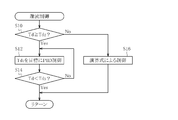
- FIG. 2 is a flowchart showing a control routine of the recirculation control of the cooling system according to the first embodiment of the present invention, which is executed by the controller 40, and will be described along the flowchart.
- step S10 it is determined whether or not the temperature Td of the discharged refrigerant detected by the discharged refrigerant temperature sensor 17 is equal to or higher than a predetermined temperature Td2. If the determination result is true (Yes) and it is determined that the temperature Td of the discharged refrigerant is equal to or higher than the predetermined temperature Td2, the process proceeds to step S12. In step S12, feedback control of the flow rate control valve 33 is performed so that the temperature Td of the discharged refrigerant becomes a target temperature (target discharged refrigerant temperature) Td1 (Td1 ⁇ Td2).
- step S20 the valve operation amount M1 corresponding to the deviation amount between the target temperature Td1 of the flow rate control valve 33 by the feedback control and the temperature Td of the discharged refrigerant is determined.
- step S22 it is determined whether or not the valve operation amount M1 is greater than or equal to an upper limit value M1max set in advance by a test. If the determination result is false (No), the valve operation amount M1 is less than the upper limit value M1max.
- step S24 the valve operation amount M1 is used as it is. On the other hand, if the determination result is true (Yes) and the valve operation amount M1 is greater than or equal to the upper limit value M1max, the process proceeds to step S26, and the valve operation amount M1 is set to the upper limit value M1max.
- the valve of the flow rate control valve 33 is used as described above.
- the flow control valve 33 is controlled to the valve opening side to increase the amount of oil recirculated to the compressor 10, while the temperature Td of the discharged refrigerant is When the temperature falls below the target temperature Td1, the flow rate control valve 33 is controlled to the valve closing side to reduce the amount of oil that circulates.
- the amount of oil recirculated to the compressor 10 is increased as the temperature Td of the discharged refrigerant is increased, and is decreased as the temperature Td of the discharged refrigerant is decreased.
- the feedback control is performed so that the temperature Td of the discharged refrigerant can be satisfactorily converged to the target temperature Td1 by suppressing the temperature rise of the refrigerant due to oil.
- PID control is preferably selected as feedback control from the viewpoint of control stability.
- the valve operation amount M1 of the flow control valve 33 is equal to or higher than the upper limit value M1max
- the valve operation amount M1 is set to the upper limit value M1max so that the oil recirculation amount does not become excessive. For example, if there is a high outside air temperature or if there is a sudden load fluctuation due to product replacement in a refrigerated showcase, etc., if there is no upper limit, the amount of operation will be excessive in feedback control, and oil will be more than necessary.
- it is supplied, by setting the upper limit value M1max it is possible to prevent excessive oil supply and to suppress a decrease in the refrigerant circulation amount.
- step S14 it is determined whether or not the temperature Td of the discharged refrigerant is lower than a predetermined temperature Td3 (Td3 ⁇ Td2). If the determination result is false (No) and it is determined that the temperature Td of the discharged refrigerant is equal to or higher than the predetermined temperature Td3, feedback control is continued in step S12.
- the routine is exited and the process returns to step S10. That is, when the temperature Td of the discharged refrigerant cannot be maintained at the target temperature Td1 due to factors such as a low outside air temperature, the temperature Td of the discharged refrigerant has become lower than the predetermined temperature Td3 (hysteresis value). End feedback control.
- Step S10 opening / closing control of the flow rate control valve 33 is performed based on an arithmetic expression (predetermined arithmetic expression).
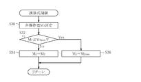
- valve operation amount M2 of the flow control valve 33 is determined by calculation based on the calculation formula of the following formula (1).
- Valve operation amount M2 [A / outside air temperature] + [B ⁇ outside air temperature ⁇ gauge pressure] + [table value] + [C ⁇ compressor rotational speed] ⁇ [D ⁇ high / low pressure difference] (1)
- the outside air temperature (oil flow rate correlation value) is a value detected by the outside air temperature sensor 41
- the gauge pressure is the pressure PH detected by the high pressure sensor 15
- the compressor rotation speed is detected by the compressor rotation speed sensor 42.
- the difference between the high pressure and the low pressure is the difference between the high pressure PH detected by the high pressure sensor 15 and the low pressure PL detected by the low pressure sensor 16 (PH ⁇ PL).
- C, and D represent coefficients.
- the table value is a reference valve opening degree of the flow rate control valve 33 set in advance based on the pressure on the high pressure side from the viewpoint of ease of recirculation.
- the pressure on the high pressure side (oil flow rate correlation value) PH is The value is set so that the opening degree decreases as the pressure rises, and the opening degree increases more easily as the pressure PH decreases (predetermined table value).
- the opening degree of the flow control valve 33 is preferably increased.
- factors factors that affect the ease of oil recirculation in addition to the discharge refrigerant temperature Td (outside air temperature, high-pressure side pressure, etc.), and only one target temperature Td1 is set as the target value. This feedback control is not suitable for controlling the opening degree of the flow control valve 33.
- the valve operation amount of the flow rate control valve 33 based on the degree of a plurality of factors (oil flow rate correlation values) affecting the oil viscosity such as the outside air temperature, the pressure on the high pressure side, and the oil flow rate. M2 is obtained.
- the flow rate control valve 33 is controlled to open to increase the degree of oil flow and return to the compressor 10
- the amount of oil flowing back is prevented by decreasing the degree of oil flow by controlling the flow rate control valve 33 to the valve closing side as the outside air temperature rises. Do not increase more than necessary.
- the third term [table value] is basically used, and the opening degree of the flow control valve 33 is first made inversely proportional to the outside air temperature in the first term [A / outside air temperature].
- the second term [B ⁇ outside air temperature ⁇ gauge pressure] it is necessary to consider an increase in the temperature Td of the discharged refrigerant in the vicinity of the predetermined temperature Td2 even if the temperature Td of the discharged refrigerant is lower than the predetermined temperature Td2.
- the product of the outside air temperature and the pressure on the high pressure side is used [table value]. Correct.
- the opening degree of the flow control valve 33 is corrected to the larger side so as to increase the oil as the machine rotational speed increases (correction term).
- the fifth term [D ⁇ high-low pressure difference] the larger the pressure difference between the high-pressure side and the low-pressure side (PH ⁇ PL), the easier the recirculation occurs. Therefore, the flow rate is increased according to the increase in the pressure difference to suppress excessive recirculation.
- the opening degree of the control valve 33 is corrected to the small side.
- step S32 the upper limit value is determined in the same manner as in the feedback control, and it is determined whether or not the valve operation amount M2 is greater than or equal to the upper limit value M2max set in advance by the test, and the determination result is false (No).
- the process proceeds to step S34, and the valve operation amount M2 is used as it is.
- the process proceeds to step S36, where the valve operation amount M2 is set to the upper limit value M2max.
- the outside air temperature that changes depending on the season such as summer and winter can be obtained by properly using the control depending on whether or not the temperature Td of the discharged refrigerant is equal to or higher than the predetermined temperature Td2.
- the opening degree of the flow control valve 33 is corrected to the larger side so that the amount of oil recirculation is increased.
- the function of suppressing the temperature rise of the refrigerant due to the oil can also prevent the temperature rise of the compressor 10, and more effectively realize the lubrication and sealing performance of the compressor 10 and the improvement of the cooling efficiency. Is possible.
- the outside air temperature is used as a parameter as the oil flow rate correlation value in the equation (1), but this is because the temperature Td of the discharged refrigerant changes and the oil viscosity changes due to the outside air temperature. If the outside air temperature is used as a parameter, the control is easy, or the outside temperature is also used for other controls (fan control of the heat source side heat exchanger, etc.), and the cost can be reduced by sharing. However, in equation (1), instead of the outside air temperature, the oil flow rate correlation value, the oil viscosity and thus the temperature Td of the discharged refrigerant that directly affects the oil flow rate, or the oil temperature may be used as a parameter. However, it is possible to obtain the same effect as described above.
- the expression (1) has the term [table value] as the reference valve opening of the flow control valve 33, but instead of [table value], the higher the pressure PH on the high pressure side, the higher the pressure.
- the function [f (PH)] may be used such that the opening degree is small and the opening degree is large and the oil easily recirculates as the pressure PH decreases.
- Formula (1) can be comprised with a perfect arithmetic expression.
- the oil cooler 31 is not essential and may be omitted.
- FIG. 5 is a flowchart showing a control routine of the recirculation control of the cooling system according to the second embodiment of the present invention executed by the controller 40, and will be described along the flowchart.
- step S10 when the operation of the cooling system is started, first, in step S10, whether or not the temperature Td of the discharged refrigerant detected by the discharged refrigerant temperature sensor 17 is equal to or higher than the predetermined temperature Td2 as in FIG. Is determined. If the determination result is false (No) and it is determined that the temperature Td of the discharged refrigerant is lower than the predetermined temperature Td2, the process proceeds to step S16 '. In step S16 ', unlike the case of the first embodiment, the flow control valve 3 is controlled based on the table value.
- the table value is the same as [Table value], which is the third term of the above formula (1), and is set in advance based on each high pressure on the high pressure side from the viewpoint of easy recirculation as described above.
- the reference valve opening of the flow control valve 33 is such that the opening decreases as the pressure on the high pressure side (oil flow correlation value) increases, and the opening increases as the pressure decreases, so that the oil flow does not decrease even at low temperatures. (Predetermined table value).
- the fact that the pressure on the high pressure side rises and falls means that the temperature Td of the discharged refrigerant also rises and falls.
- the table value basically decreases as the temperature Td of the discharged refrigerant and thus the outside air temperature (oil flow rate correlation value) increases, and increases as the temperature Td of the discharged refrigerant or the outside air temperature decreases. It can be said that the oil flow rate is set not to decrease.
- the compressor 10 is controlled by controlling the flow rate control valve 33 to the valve opening side as the pressure on the high pressure side decreases, that is, as the temperature Td of the discharged refrigerant and thus the outside air temperature decreases.
- the flow control valve 33 is controlled to the valve closing side.
- step S12 as in the case of the first embodiment, feedback control of the flow rate control valve 33, for example, PID control is performed so that the temperature Td of the discharged refrigerant becomes the target temperature Td1 (Td1 ⁇ Td2).
- the temperature Td of the discharged refrigerant can be converged to the target temperature Td1 satisfactorily by the function of suppressing the temperature rise of the refrigerant due to oil.
- control is performed using the temperature Td of the discharged refrigerant detected by the discharged refrigerant temperature sensor 17, but it correlates with the temperature Td of the discharged refrigerant instead of the temperature Td of the discharged refrigerant.
- the temperature of the discharge part of the compressor 10 may be detected as a value, and control may be performed using this.
- the opening degree of the flow rate control valve 33 is variably controlled as the oil recirculation control means.
- the oil recirculation control means can control the open / close time.
- a control valve for example, a duty control valve
- a parallel bypass pipe may be provided with an open / close valve to control open / close of each open / close valve. There may be.
- ammonia is used as the refrigerant used in the cooling system, but carbon dioxide may be used as the refrigerant, and the cooling system is configured so that the refrigerant is in a supercritical state. May be.
- the solenoid valve 32 and the flow control valve 33 are provided, the solenoid valve 32 may be abbreviate
- the present invention relates to a cooling system used for indoor air conditioning, a refrigerator / freezer, a refrigerated showcase, etc., regardless of the outside air temperature or the temperature condition of refrigerant discharged from the compressor, ensuring the lubrication and sealing performance of the compressor and cooling efficiency. It is a cooling system that can effectively realize improvement.
Landscapes
- Engineering & Computer Science (AREA)
- Physics & Mathematics (AREA)
- Mechanical Engineering (AREA)
- Thermal Sciences (AREA)
- General Engineering & Computer Science (AREA)
- Chemical & Material Sciences (AREA)
- Analytical Chemistry (AREA)
- Power Engineering (AREA)
- Air Conditioning Control Device (AREA)
Abstract
【課題】外気温度や圧縮機から吐出した冷媒の温度状況に拘わらず、圧縮機の潤滑及びシール性能の確保と冷却効率の向上とを効果的に実現可能な冷却システムを提供する。 【解決手段】圧縮機の吐出側にオイルセパレータを備えるとともに該オイルセパレータによって冷媒から分離されたオイルを圧縮機の吸入側に戻すオイル還流路を備え、オイルがオイル還流路を還流する際、吐出冷媒温度Tdが所定温度Td2以上のときには、PID制御により、吐出冷媒温度Tdの上昇に応じてオイルの流れ度合いを増大させ、吐出冷媒温度Tdの下降に応じてオイルの流れ度合いを減少させ(S10,S12)、一方、吐出冷媒温度Tdが所定温度Td2未満のときには、所定の演算式により、外気温度の上昇に応じてオイルの流れ度合いを減少させる(S10,S16)。
Description
本発明は、室内空調、冷凍・冷蔵庫、冷蔵ショーケース等に用いられる冷却システムに関する。
この種の冷却システムは、圧縮機、凝縮器、膨張弁及び蒸発器からなる冷凍回路を備え、外気を利用して凝縮器を冷却するようにしている。かかる冷却システムでは、通常、冷媒には主として圧縮機の潤滑やシールを目的として潤滑油が混入されている。また、この潤滑油は、圧縮しても温度が上がらないことから、圧縮機により圧縮される冷媒の昇温を抑えて凝縮器の機能を補う働きも有している。
ところで、かかる潤滑油は、基本的には圧縮機において必要なものであるため、圧縮機から吐出された冷媒からオイルセパレータで潤滑油を分離回収して圧縮機の吸込側に還流させる構成の冷却システムが種々開発されている(特許文献1、2参照)。これら特許文献1、2の技術によれば、例えば外気温度に応じて開閉弁を制御することで圧縮機の吸込側に還流させる潤滑油の量を調整可能であり、外気温度に拘わらず、圧縮機の潤滑やシールを実現することができ、さらには冷媒の昇温の抑制をも適宜実現することが可能である。
特許文献1の技術では、外気温度に応じ、外気温度が高いと開閉弁の開度を小さくして潤滑油の圧縮機への還流量を少なくし、外気温度が低く潤滑油の粘度が高いと開閉弁の開度を大きくして潤滑油の圧縮機への還流量を多くして圧縮機の潤滑及びシール性能を確保するようにしており、外気温度が高く潤滑油の粘度が低い場合には開閉弁の開度が小さくなるために潤滑油の量が減ることになり、冷媒の昇温を十分に抑制することができず、冷却効率の向上が図れないという問題がある。
特許文献2の技術では、基本的には上記特許文献1の技術と同様に外気温度に応じて潤滑油の圧縮機への還流量を制御して圧縮機の潤滑を確保するとともに、圧縮機から吐出した冷媒の温度に応じ、該冷媒の温度が低いと開閉弁の開度を小さくして潤滑油の圧縮機への還流量を少なくし、該冷媒の温度が高いと開閉弁の開度を大きくして潤滑油の圧縮機への還流量を多くし冷媒の昇温を抑えて冷却効率の向上を図るようにしているが、これらの制御は相反する要素が大きいことから、これらの制御を如何に使い分け、圧縮機の潤滑及びシール性能の確保と冷却効率の向上とを如何に効果的に実現させるかが課題となる。
また、上記特許文献1、2の技術では、圧縮機への潤滑油の還流量が多過ぎることもあり得、このように潤滑油の還流量が過多になると、その分冷媒の量が減少して冷却効率が却って悪化するという問題もある。そして、潤滑油は温度により粘性が変化するものであり、外気温度に応じて潤滑油の還流量が容易に増減してしまうため、圧縮機の潤滑及びシール性能の確保と冷却効率の向上とを実現するに当たり、特に外気温度が低いような状況において、粘性の変化に対し潤滑油の還流量を如何に適正量に制御するかが課題となる。
本発明は、このような課題に鑑みなされたもので、外気温度や圧縮機から吐出した冷媒の温度状況に拘わらず、圧縮機の潤滑及びシール性能の確保と冷却効率の向上とを効果的に実現可能な冷却システムを提供することを目的とする。
上記の目的を達成するべく、請求項1の冷却システムは、圧縮機、熱源側熱交換器、膨張手段及び利用側熱交換器からなる冷凍回路を備えた冷却システムにおいて、前記圧縮機の吐出側に設けられ、前記圧縮機から吐出した冷媒に含まれるオイルを冷媒から分離するオイルセパレータと、前記オイルセパレータによって分離されたオイルを前記圧縮機の吸入側に戻すオイル還流路と、前記オイル還流路を通るオイルの流れ度合いを制御するオイル還流制御手段と、前記圧縮機から吐出した冷媒の吐出冷媒温度を検出する吐出冷媒温度検出手段と、前記オイル還流路を通るオイルの流量に影響を与える要因の程度をオイル流量相関値として検出するオイル流量相関値検出手段とを備え、前記オイル還流制御手段は、前記吐出冷媒温度検出手段により検出された吐出冷媒温度が所定値以上であるときには、吐出冷媒温度の上昇に応じてオイルの流れ度合いを増大させるとともに吐出冷媒温度の下降に応じてオイルの流れ度合いを減少させ、吐出冷媒温度が所定値未満であるときには、前記オイル流量相関値検出手段により検出されたオイル流量相関値のオイルの流量を減少させる方向への変化に応じてオイルの流れ度合いを増大させることを特徴とする。
請求項2の冷却システムでは、請求項1において、前記オイル還流制御手段は、前記オイル還流路を通るオイルの流量の上限値を有することを特徴とする。請求項3の冷却システムでは、請求項1または2において、前記オイル還流制御手段は、吐出冷媒温度が所定値以上であるときには目標吐出冷媒温度に対してオイルの流れ度合いをフィードバック制御し、吐出冷媒温度が所定値未満であるときには前記オイル流量相関値のオイルの流量を減少させる方向への変化に応じてオイルの流れ度合いを増大させる所定の演算式に基づき制御することを特徴とする。
請求項4の冷却システムでは、請求項1または2において、前記オイル流量相関値検出手段はオイル流量相関値としての外気温度を検出する外気温度検出手段を含み、前記オイル還流制御手段は、吐出冷媒温度が所定値以上であるときには目標吐出冷媒温度に対し吐出冷媒温度に応じてオイルの流れ度合いをフィードバック制御し、吐出冷媒温度が所定値未満であるときには前記外気温度検出手段により検出された外気温度の下降に応じてオイルの流れ度合いを増大させる所定の演算式に基づき制御することを特徴とする。
請求項5の冷却システムでは、請求項3または4において、前記圧縮機の回転速度を検出する回転速度検出手段を有し、前記所定の演算式は前記圧縮機の回転速度による補正項を含み、前記オイル還流制御手段は、吐出冷媒温度が所定値未満であるときにはオイルの流れ度合いを所定の演算式に基づき前記回転速度検出手段により検出された前記圧縮機の回転速度で補正して制御することを特徴とする。
請求項6の冷却システムでは、請求項1乃至5のいずれかにおいて、前記オイル還流制御手段は、吐出冷媒温度が所定値以上であるときには目標吐出冷媒温度に対してオイルの流れ度合いをフィードバック制御し、吐出冷媒温度が所定値未満であるときには前記オイル流量相関値のオイルの流量を減少させる方向への変化に応じてオイルの流れ度合いを増大させる所定のテーブル値に基づき制御することを特徴とする。
請求項7の冷却システムでは、請求項1乃至5のいずれかにおいて、前記オイル流量相関値検出手段はオイル流量相関値としての外気温度を検出する外気温度検出手段を含み、前記オイル還流制御手段は、吐出冷媒温度が所定値以上であるときには目標吐出冷媒温度に対してオイルの流れ度合いをフィードバック制御し、吐出冷媒温度が所定値未満であるときには前記外気温度検出手段により検出された外気温度の下降に応じてオイルの流れ度合いを増大させる所定のテーブル値に基づき制御することを特徴とする。
請求項1記載の冷却システムによれば、冷媒の循環する冷凍回路を備えた冷却システムにおいて、圧縮機の吐出側にオイルセパレータを備えるとともに該オイルセパレータによって冷媒から分離されたオイルを圧縮機の吸入側に戻すオイル還流路を備え、オイルがオイル還流路を還流する際、オイル還流制御手段により、吐出冷媒温度検出手段により検出された吐出冷媒温度が所定値以上であるときには、吐出冷媒温度の上昇に伴う吐出冷媒温度の変化に応じてオイルの流れ度合いは増大させられ、吐出冷媒温度の下降に伴う吐出冷媒温度の変化に応じてオイルの流れ度合いは減少させられ、一方、吐出冷媒温度が所定値未満であるときには、オイル流量相関値検出手段により検出されたオイル流量相関値のオイルの流量を減少させる方向への変化に応じてオイルの流れ度合いは増大させられる。
従って、吐出冷媒温度が所定値以上である場合には、吐出冷媒温度の上昇に応じてオイルの還流量を増大させ、オイルによる冷媒の昇温を抑える働きにより冷媒ひいては圧縮機の昇温を抑えることができ、吐出冷媒温度が所定値未満である場合には、オイル流量相関値のオイルの流量を減少させる方向への変化に伴うオイルの粘性の増大によってオイルが流れ難くなってもオイルの還流量の低下を防止でき、オイルによる圧縮機の潤滑及びシール性能を確保することができる。
これにより、オイル還流制御において制御を適切に使い分け、夏季及び冬季等の季節により変化する外気温度や圧縮機から吐出した冷媒の温度状況に拘わらず、圧縮機の潤滑及びシール性能の確保と冷却効率の向上とを効果的に実現することができる。請求項2記載の冷却システムによれば、オイル還流制御手段はオイル還流路を通るオイルの流量の上限値を有するので、オイルの還流量が過多になることを防止でき、これにより冷媒循環量の減少を抑え、冷却効率を維持することができる。
請求項3、4記載の冷却システムによれば、オイルがオイル還流路を還流する際、オイル還流制御手段により、吐出冷媒温度が所定値以上であるときには目標吐出冷媒温度に対してオイルの流れ度合いはフィードバック制御され、吐出冷媒温度が所定値未満であるときにはオイル流量相関値、例えば外気温度等に応じてオイルの流れ度合いは所定の演算式に基づき制御される。
従って、吐出冷媒温度が所定値以上である場合には、フィードバック制御を用いることで吐出冷媒温度の上昇に応じてオイルの還流量を増大させ、オイルによる冷媒の昇温を抑える働きにより冷媒ひいては圧縮機の昇温を抑えることができ、吐出冷媒温度が所定値未満である場合には、オイル流量相関値、例えば外気温度等に応じた所定の演算式を用いることでオイル流量相関値のオイルの流量を減少させる方向への変化に伴うオイルの粘性の増大によってオイルが流れ難くなってもオイルの還流量の低下を防止でき、オイルによる圧縮機の潤滑及びシール性能を確保することができる。
これにより、オイル還流制御においてフィードバック制御と所定の演算式による制御とを適切に使い分け、外気温度や圧縮機から吐出した冷媒の温度状況に拘わらず、圧縮機の潤滑及びシール性能の確保と冷却効率の向上とを効果的に実現することができる。請求項5記載の冷却システムによれば、所定の演算式は圧縮機の回転速度による補正項を含み、オイル還流制御手段は、吐出冷媒温度が所定値未満であるときにはオイルの流れ度合いを所定の演算式に基づき圧縮機の回転速度で補正して制御するので、圧縮機の回転速度が上昇し負荷が高くなるほど圧縮機が昇温し易くなるのであるが、このような場合でも圧縮機の昇温を抑えつつ、オイルによる圧縮機の潤滑及びシール性能を確保することができる。
これにより、外気温度や圧縮機から吐出した冷媒の温度状況に拘わらず、圧縮機の潤滑及びシール性能の確保と冷却効率の向上とをより一層効果的に実現することができる。請求項6、7記載の冷却システムによれば、オイルがオイル還流路を還流する際、オイル還流制御手段により、吐出冷媒温度が所定値以上であるときには目標吐出冷媒温度に対してオイルの流れ度合いはフィードバック制御され、吐出冷媒温度が所定値未満であるときにはオイル流量相関値、例えば外気温度等に応じてオイルの流れ度合いは所定のテーブル値に基づき制御される。
従って、吐出冷媒温度が所定値以上である場合には、フィードバック制御を用いることで吐出冷媒温度の上昇に応じてオイルの還流量を増大させ、オイルによる冷媒の昇温を抑える働きにより冷媒ひいては圧縮機の昇温を抑えることができ、吐出冷媒温度が所定値未満である場合には、オイル流量相関値、例えば外気温度等に応じた所定のテーブル値を用いることでオイル流量相関値のオイルの流量を減少させる方向への変化に伴うオイルの粘性の増大によってオイルが流れ難くなってもオイルの還流量の低下を防止でき、比較的簡単にオイルによる圧縮機の潤滑及びシール性能を確保することができる。
これにより、オイル還流制御においてフィードバック制御と所定のテーブル値による制御とを適切に使い分け、外気温度や圧縮機から吐出した冷媒の温度状況に拘わらず、圧縮機の潤滑及びシール性能の確保と冷却効率の向上とを比較的簡単な構成にして効果的に実現することができる。
以下、図面により本発明の一実施形態について説明する。先ず、第1実施例を説明する。図1は本発明に係る冷却システムを示す概略構成図である。図1に示す冷却システムは、広く冷凍・冷蔵庫、冷蔵ショーケース、空調での冷房等に用いられ、冷媒の循環する冷凍回路を有し、基本構成として圧縮機10、空冷式の熱源側熱交換器11、膨張手段としての膨張弁12及び利用側熱交換器13を備えて構成されている。
当該冷却システムでは、冷凍回路を循環する冷媒にオイル(潤滑油)が混合され、当該オイルによって主として圧縮機10の潤滑及びシールを行うことが可能である。さらに、一般的に当該オイルは圧縮機10に圧縮されても冷媒に比して温度が上がらないことから、圧縮機10により圧縮される冷媒の昇温を抑えて熱源側熱交換器11の機能を補うことも可能である。
このように、冷媒に混合されるオイルは、圧縮機10にて使用されるものである。故に、当該冷却システムでは、さらに、冷凍回路のうち圧縮機10の吐出側に位置してオイルセパレータ20が設けられ、当該オイルセパレータ20で分離したオイルを冷凍回路の圧縮機10の吸入側に還流し合流させるようにオイル還流路30が配設されている。また、オイル還流路30には還流するオイルを冷却する空冷式のオイルクーラ31が介装されている。
これにより、当該冷却システムは、圧縮機10の吐出により、冷媒を圧縮機10→オイルセパレータ20→熱源側熱交換器11→膨張弁12→利用側熱交換器13→圧縮機10の順に循環させ、且つ、圧縮機10から冷媒とともに吐出したオイルを圧縮機10→オイルセパレータ20→オイルクーラ31→圧縮機10の順に循環させることができる。ここでは、熱源側熱交換器11は放熱器として機能し、利用側熱交換器13は蒸発器として機能する。この際、冷媒やオイルは、圧縮機10→オイルセパレータ20→熱源側熱交換器11→膨張弁12の間は高圧力で循環し(以下、高圧側ともいう)、膨張弁12→利用側熱交換器13→圧縮機10間は低圧力で循環する(以下、低圧側ともいう)。
なお、図1は空調では冷房の場合を示すが、本発明は暖房の場合にも適用可能である。暖房の場合には、図示しない四方弁の切り換えにより、冷媒等は圧縮機10→オイルセパレータ20→利用側熱交換器13→膨張弁12→熱源側熱交換器11→圧縮機10の順に循環する。この場合、利用側熱交換器13は放熱器として機能し、熱源側熱交換器11は蒸発器として機能するが、オイルは冷房の場合と同様に、圧縮機10→オイルセパレータ20→オイルクーラ31→圧縮機10の順に循環する。
ここに、当該冷却システムで使用される冷媒は、例えばアンモニアである。また、オイル還流路30には、オイルクーラ31と圧縮機10との間に位置して電磁弁32と流量制御弁33とが介装されている。電磁弁32は、オイル還流路30を開閉するものであり、コントローラ40に電気的に接続されている。また、流量制御弁(オイル還流制御手段)33は、弁の開閉度合いを変えてオイル還流路30を還流するオイルの流れ度合いを調節する制御弁、例えばステッピングモータ駆動方式の比例制御弁であり、やはりコントローラ40に電気的に接続されている。
また、冷凍回路のうち圧縮機10の吐出側には、高圧側の冷媒の圧力(オイル流量相関値)PHを検出する高圧側圧力センサ(オイル流量相関値検出手段)15が配設され、圧縮機10の吸入側には、低圧側の冷媒の圧力PLを検出する低圧側圧力センサ16が配設されており、それぞれコントローラ40に電気的に接続されている。さらに、冷凍回路のうち圧縮機10の吐出側には、圧縮機10から吐出したガス状の吐出冷媒(オイルを含む)の温度(吐出冷媒温度、オイル流量相関値)Tdを検出する吐出冷媒温度センサ(吐出冷媒温度検出手段、オイル流量相関値検出手段)17が設けられており、やはりコントローラ40に電気的に接続されている。
コントローラ40は、冷却システムの種々の制御を行う電子制御装置であり、その入力側には上述の如く高圧側圧力センサ15、低圧側圧力センサ16、吐出冷媒温度センサ17の他、外気の温度(オイル流量相関値)を検出する外気温センサ(オイル流量相関値検出手段、外気温度検出手段)41、圧縮機10の回転速度を検出する圧縮機回転速度センサ(回転速度検出手段)42や種々のセンサ類が接続され、出力側には上述の如く電磁弁32、流量制御弁33の他、種々のデバイス類が接続されている。
これより、電磁弁32、流量制御弁33は、各種入力信号に応じてコントローラ40によって作動される(オイル還流制御手段)。電磁弁32は、圧縮機10の運転時には開いた状態とされ、圧縮機10の運転停止時には閉じた状態とされる。つまり、電磁弁32は、圧縮機10の運転時にはオイルを圧縮機10の吸入側に戻し、圧縮機10の運転停止時にはオイルが圧縮機10に戻ることを防止する。
また、流量制御弁33は、高圧側圧力センサ15により検出された高圧側の冷媒の圧力PH、低圧側圧力センサ16により検出された低圧側の冷媒の圧力PL、吐出冷媒温度センサ17により検出された吐出冷媒の温度Td等に基づき開閉度合いが制御され、これによりオイル還流路30を還流するオイルの流れ度合いが調節される。例えば、オイルの粘度が一定であれば、流量制御弁33の弁開度を広げてオイルの流れ度合いを増大させてオイル流量を増加させ、弁開度を狭めてオイルの流れ度合いを減少させてオイル流量を低下させることが可能である。一方、オイルの粘度が変化するような場合にあっては、オイルの温度が低下するとオイルの粘度は上昇してオイルが流れ難くなることから、流量制御弁33の弁開度を広げてオイルの流れ度合いを増大させることでオイル流量が減少することを防止可能である。
以下、このように構成された本発明の第1実施例に係る冷却システムの作用について詳しく説明する。図2は、コントローラ40の実行する本発明の第1実施例に係る冷却システムの還流制御の制御ルーチンを示すフローチャートであり、以下、同フローチャートに沿い説明する。
冷却システムの運転が開始されると、先ずステップS10では、吐出冷媒温度センサ17により検出された吐出冷媒の温度Tdが所定温度Td2以上であるか否かを判別する。判別結果が真(Yes)で吐出冷媒の温度Tdが所定温度Td2以上と判定された場合には、ステップS12に進む。ステップS12では、吐出冷媒の温度Tdが目標温度(目標吐出冷媒温度)Td1(Td1≧Td2)となるように流量制御弁33のフィードバック制御を行う。
図3を参照すると、フィードバック制御の制御ルーチンがフローチャートで示されており、ここでは同フローチャートが実行される。ステップS20では、フィードバック制御による流量制御弁33の目標温度Td1と吐出冷媒の温度Tdとの偏差量に対応した弁操作量M1を決定する。そして、ステップS22では、上記弁操作量M1が試験により予め設定した上限値M1max以上であるか否かを判別し、判別結果が偽(No)で弁操作量M1が上限値M1max未満である場合には、ステップS24に進み弁操作量M1をそのまま使用する。一方、判別結果が真(Yes)で弁操作量M1が上限値M1max以上である場合には、ステップS26に進み、弁操作量M1を上限値M1maxとする。
吐出冷媒の温度Tdが高くなると冷媒の温度を下げる必要があるところ、上述したようにオイルは冷媒の昇温を抑える働きをすることから、当該フィードバック制御では、上記の如く流量制御弁33の弁操作量M1を求め、吐出冷媒の温度Tdが目標温度Td1を越えると流量制御弁33を開弁側に制御して圧縮機10に還流するオイルの量を増加させ、一方吐出冷媒の温度Tdが目標温度Td1を下回ると流量制御弁33を閉弁側に制御して還流するオイルの量を減少させる。
このように、吐出冷媒の温度Tdが所定温度Td2以上と高い場合には、圧縮機10に還流するオイルの量を吐出冷媒の温度Tdが高くなるほど増加させ、吐出冷媒の温度Tdが低くなるほど減少させるようにフィードバック制御を行うので、オイルによる冷媒の昇温を抑える働きによって吐出冷媒の温度Tdを良好に目標温度Td1に収束させることができる。これにより、吐出冷媒の温度Tdが所定温度Td2以上と高い場合であっても、冷媒ひいては圧縮機10の昇温を防止して冷却システムの冷却効率の向上を図りながら、オイルによる圧縮機10の潤滑及びシール性能を確保することができる。
ここに、フィードバック制御としては制御の安定性からPID制御が選択されるのが好ましい。また、流量制御弁33の弁操作量M1が上限値M1max以上である場合には、弁操作量M1を上限値M1maxとして、オイルの還流量が過多にならないようにしている。例えば、高外気温になったり、冷蔵ショーケース等において商品が入れ換わることで急激な負荷変動があったりすると、上限値がなければフィードバック制御では操作量が過剰に大きくなり、オイルが必要以上に供給されてしまうのであるが、上限値M1maxを定めることで、過剰なオイル供給を防ぐことができ、冷媒循環量の減少を抑えることができる。
なお、ここでは制御ルーチンにおいて上限値M1maxを設けてソフトウェア上でオイル流量の上限値を設定しているが、リリース弁等を用いてオイル流量の上限値をハードウェアで構成するようにしてもよい。図2に戻り、ステップS14では、吐出冷媒の温度Tdが所定温度Td3(Td3<Td2)未満であるか否かを判別する。判別結果が偽(No)で吐出冷媒の温度Tdが所定温度Td3以上と判定された場合には、ステップS12においてフィードバック制御を継続する。一方、判別結果が真(Yes)で吐出冷媒の温度Tdが所定温度Td3未満と判定された場合には、当該ルーチンを抜けてステップS10に戻る。即ち、外気温度が低い等の要因により吐出冷媒の温度Tdを目標温度Td1に維持できないようになっている場合には、吐出冷媒の温度Tdが所定温度Td3(ヒステリシス値)未満になったことをもってフィードバック制御を終了する。
この場合には、上述の如く吐出冷媒の温度Tdは所定温度Td3未満であり且つ所定温度Td2未満であることから、ステップS10の判別結果は偽(No)となり、ステップS16に進む。ステップS16では、演算式(所定の演算式)に基づいて流量制御弁33の開閉制御を行う。
図4を参照すると、演算式による制御の制御ルーチンがフローチャートで示されており、ここでは同フローチャートが実行される。ステップS30では、次式(1)の演算式に基づいて流量制御弁33の弁操作量M2を演算により決定する。
弁操作量M2=[A/外気温度]+[B×外気温度×ゲージ圧]+[テーブル値]+[C×圧縮機回転速度]-[D×高低圧差] ・・・(1)
ここに、外気温度(オイル流量相関値)は外気温センサ41により検出された値、ゲージ圧は高圧側圧力センサ15により検出された圧力PH、圧縮機回転速度は圧縮機回転速度センサ42により検出された値、高低圧差は高圧側圧力センサ15により検出された高圧側の圧力PHと低圧側圧力センサ16により検出された低圧側の圧力PLとの差(PH-PL)であり、A、B、C、Dはそれぞれ係数を示す。また、テーブル値は、還流のし易さという観点から高圧側の圧力に基づき予め設定された流量制御弁33の基準弁開度であり、ここでは高圧側の圧力(オイル流量相関値)PHが上昇するほど開度が小さく、圧力PHが低下するほど開度が大きく還流し易くなるように値が設定されている(所定のテーブル値)。
弁操作量M2=[A/外気温度]+[B×外気温度×ゲージ圧]+[テーブル値]+[C×圧縮機回転速度]-[D×高低圧差] ・・・(1)
ここに、外気温度(オイル流量相関値)は外気温センサ41により検出された値、ゲージ圧は高圧側圧力センサ15により検出された圧力PH、圧縮機回転速度は圧縮機回転速度センサ42により検出された値、高低圧差は高圧側圧力センサ15により検出された高圧側の圧力PHと低圧側圧力センサ16により検出された低圧側の圧力PLとの差(PH-PL)であり、A、B、C、Dはそれぞれ係数を示す。また、テーブル値は、還流のし易さという観点から高圧側の圧力に基づき予め設定された流量制御弁33の基準弁開度であり、ここでは高圧側の圧力(オイル流量相関値)PHが上昇するほど開度が小さく、圧力PHが低下するほど開度が大きく還流し易くなるように値が設定されている(所定のテーブル値)。
吐出冷媒の温度Tdが所定温度Td2未満と低い場合には、オイルによる吐出冷媒の冷却の役割比重が小さくなる一方、吐出冷媒の温度Tdが低下するほどオイルの粘性が高まり流れ難くなる傾向にあり、潤滑を確保するため流量制御弁33の開度を大きくするのがよい。しかしながら、オイルの還流のし易さに影響を与える因子(要因)は上記吐出冷媒の温度Td以外に複数存在し(外気温度、高圧側の圧力等)、目標温度Td11つの値のみを目標値とするフィードバック制御では流量制御弁33の開度の制御に不適である。従って、ここでは外気温度、高圧側の圧力等のオイルの粘度ひいてはオイル流量に影響を与える複数の因子の程度(オイル流量相関値)に基づき上記式(1)に従い流量制御弁33の弁操作量M2を求めるようにし、基本的にはオイル流量に相関する外気温度が低下するに連れて流量制御弁33を開弁側に制御してオイルの流れ度合いを増大させて圧縮機10に還流するオイルの量がオイルの粘性の増大により低下することを防止し、一方外気温度が上昇するに連れて流量制御弁33を閉弁側に制御してオイルの流れ度合いを減少させ、還流するオイルの量を必要以上に増加させないようにする。
即ち、式(1)では、第3の項の[テーブル値]を基本とし、先ず最初の項である[A/外気温度]において流量制御弁33の開度を外気温度に反比例させる。第2の項である[B×外気温度×ゲージ圧]では、吐出冷媒の温度Tdが所定温度Td2未満であっても所定温度Td2付近では吐出冷媒の温度Tdの上昇を考慮する必要があることから、また所定温度Td2以上に移行したとき(フィードバック制御に移行したとき)に急激な弁開度の変動が生じないようにするべく外気温度と高圧側の圧力との積でもって[テーブル値]を補正する。第4の項である[C×圧縮機回転速度]では圧縮機10の圧縮機回転速度が上昇し負荷が高くなるほど圧縮機10が昇温し易くなること、また潤滑の必要が増すことから圧縮機回転速度の上昇に応じてオイルを増やすべく流量制御弁33の開度を大側に補正する(補正項)。さらに、第5の項である[D×高低圧差]では高圧側と低圧側の圧力差(PH-PL)が大きいほど還流し易いことから過度の還流を抑えるべく圧力差の増大に応じて流量制御弁33の開度を小側に補正する。
ステップS32では、フィードバック制御の場合と同様に上限値を定めており、上記弁操作量M2が試験により予め設定した上限値M2max以上であるか否かを判別し、判別結果が偽(No)で弁操作量M2が上限値M2max未満である場合には、ステップS34に進み弁操作量M2をそのまま使用する。一方、判別結果が真(Yes)で弁操作量M2が上限値M2max以上である場合には、ステップS36に進み、弁操作量M2を上限値M2maxとする。
このように、吐出冷媒の温度Tdが所定温度Td2未満と低い場合には、圧縮機10に還流するオイルの量を外気温度が低くなればオイルの流れ度合いを増加させてオイル流量が減少するのを防止し、外気温度が高くなれば或いは流量制御弁33の弁操作量M2が上限値M2max以上である場合にはオイルが流れ過ぎないように制御を行うので、吐出冷媒の温度Tdが低い場合において圧縮機10へのオイルの還流量を十分に確保することができるとともにオイルの供給過多を防止できる。これにより、吐出冷媒の温度Tdが所定温度Td2未満と低い場合であっても、オイルによる圧縮機10の潤滑及びシール性能を十分に確保することができ、オイルの供給過多による冷却性能の低下を防止することができる。
以上のように、本発明に係る冷却システムによれば、吐出冷媒の温度Tdが所定温度Td2以上であるか否かに応じて制御を使い分けることで、夏季及び冬季等の季節により変化する外気温度ひいては吐出冷媒の温度Tdに拘わらず、圧縮機10の潤滑及びシール性能の確保と吐出冷媒の温度の上昇防止及びオイル供給過多の防止による冷却効率の向上とを効果的に実現することが可能である。
また、ここでは、圧縮機10の圧縮機回転速度に応じ、圧縮機回転速度が上昇するほど流量制御弁33の開度を大側に補正してオイルの還流量を増量させるようにするので、オイルによる冷媒の昇温を抑える働きにより、併せて圧縮機10の昇温をも防止することができ、圧縮機10の潤滑及びシール性能の確保と冷却効率の向上とをより一層効果的に実現することが可能である。
なお、ここでは、式(1)においてオイル流量相関値として外気温度をパラメータに用いるようにしているが、これは外気温度に起因して吐出冷媒の温度Tdが変化しオイルの粘度が変化することから外気温度をパラメータにすると制御が容易であり、或いは外気温度は他の制御(熱源側熱交換器のファン制御等)でも使用しており共用化によりコストダウンを図ることができるためである。しかしながら、式(1)においてオイル流量相関値として外気温度に代えてオイルの粘度ひいてはオイル流量に直接影響する吐出冷媒の温度Td、或いはオイルの温度をパラメータに用いるようにしてもよく、このようにしても上記同様の作用効果を得ることが可能である。
また、ここでは、式(1)に流量制御弁33の基準弁開度として[テーブル値]の項を有しているが、[テーブル値]に代えて、高圧側の圧力PHが上昇するほど開度が小さく、圧力PHが下降するほど開度が大きくオイルが還流し易くなるような関数[f(PH)]を用いるようにしてもよい。これにより、式(1)を完全な演算式で構成することができる。また、吐出冷媒の温度Tdが所定温度Td2以上と高い場合には、オイルクーラ31によってオイルをさらに良好に冷却可能であるが、オイルクーラ31については必須ではなく、無くてもよい。
次に、第2実施例を説明する。第2実施例では、図1に示す冷却システムの構成において上記第1実施例とは制御内容のみが異なっており、以下第1実施例と異なる点についてのみ説明する。図5は、コントローラ40の実行する本発明の第2実施例に係る冷却システムの還流制御の制御ルーチンを示すフローチャートであり、以下、同フローチャートに沿い説明する。
第2実施例では、冷却システムの運転が開始されると、先ずステップS10において、上記図2同様に吐出冷媒温度センサ17により検出された吐出冷媒の温度Tdが所定温度Td2以上であるか否かを判別する。判別結果が偽(No)で吐出冷媒の温度Tdが所定温度Td2未満と判定された場合には、ステップS16’に進む。ステップS16’では、第1実施例の場合と異なり、テーブル値に基づき流量制御弁3を制御する。
ここに、テーブル値は、上記式(1)の第3の項である[テーブル値]と同じであり、上述の如く還流のし易さという観点から高圧側の各高圧に基づき予め設定された流量制御弁33の基準弁開度であり、高圧側の圧力(オイル流量相関値)が上昇するほど開度が小さく、圧力が低下するほど開度が大きく低温下においてもオイル流量が減少しないように設定されている(所定のテーブル値)。
ここで、高圧側の圧力が上昇、下降するということは、即ち吐出冷媒の温度Tdも上昇、下降することを意味する。換言すれば、テーブル値は、基本的に吐出冷媒の温度Tdひいては外気温度(オイル流量相関値)が上昇するほど開度が小さく、吐出冷媒の温度Td或いは外気温度が低下するほど開度が大きくオイル流量が減少しないように設定されていると言える。
従って、ここでは上記テーブル値に従い、高圧側の圧力が下降するに連れて、即ち吐出冷媒の温度Tdひいては外気温度が低下するに連れて流量制御弁33を開弁側に制御して圧縮機10に還流するオイルの粘度上昇に伴う流量の減少を防止して適正なオイル流量を確保させ、一方高圧側の圧力が上昇するに連れて、即ち吐出冷媒の温度Tdひいては外気温度が上昇するに連れて流量制御弁33を閉弁側に制御する。
これにより、吐出冷媒の温度Tdが所定温度Td2未満と低い場合であっても、テーブル値を用いるという比較的簡単な構成にして、オイルによる圧縮機10の潤滑及びシール性能を確保することができる。一方、判別結果が真(Yes)で吐出冷媒の温度Tdが所定温度Td2以上と判定された場合には、ステップS12に進む。
ステップS12では、第1実施例の場合と同様、吐出冷媒の温度Tdが目標温度Td1(Td1≧Td2)となるように流量制御弁33のフィードバック制御、例えばPID制御を行う。これにより、吐出冷媒の温度Tdが所定温度Td2以上と高い場合であっても、上記同様、オイルによる冷媒の昇温を抑える働きによって吐出冷媒の温度Tdを良好に目標温度Td1に収束させることができ、冷媒ひいては圧縮機10の昇温を防止しながら、オイルによる圧縮機10の潤滑及びシール性能を確保することができる。
以上で本発明の一実施形態についての説明を終えるが、本発明は上記実施形態に限定されるものではなく、本発明の趣旨を逸脱しない範囲で種々の変更ができるものである。例えば、上記実施形態では、吐出冷媒温度センサ17により検出された吐出冷媒の温度Tdを用いて制御を行うようにしているが、吐出冷媒の温度Tdに代えて、吐出冷媒の温度Tdと相関する値として圧縮機10の吐出部の温度を検出し、これを用いて制御を行うようにしてもよい。
また、上記実施形態では、オイル還流制御手段として流量制御弁33の開度を可変制御するようにしたが、オイルの流れ度合いを変えることが可能であれば、オイル還流制御手段は開閉時間制御可能な制御弁(例えば、デューティ制御弁)を用いて開閉時間制御を行うようなものであってもよく、或いは並列バイパス管にそれぞれ開閉弁を備えて各開閉弁の開閉制御を行うようなものであってもよい。
また、上記実施形態では、冷却システムで使用される冷媒には例えばアンモニアを用いるようにしたが、冷媒に二酸化炭素を用いるようにしてもよく、冷媒が超臨界状態となるように冷却システムを構成してもよい。また、上記実施形態では、電磁弁32と流量制御弁33を備えているが、電磁弁32を省略し、流量制御弁33に電磁弁32の機能を持たせるようにしてもよい。
本発明は、室内空調、冷凍・冷蔵庫、冷蔵ショーケース等に用いられる冷却システムに関し、外気温度や圧縮機から吐出した冷媒の温度状況に拘わらず、圧縮機の潤滑及びシール性能の確保と冷却効率の向上とを効果的に実現可能な冷却システムである。
10 圧縮機
11 熱源側熱交換器
12 膨張弁
13 利用側熱交換器
15 高圧側圧力センサ(オイル流量相関値検出手段)
16 低圧側圧力センサ
17 吐出冷媒温度センサ(吐出冷媒温度検出手段、オイル流量相関値検出手段)
20 オイルセパレータ
30 オイル還流路
31 オイルクーラ
33 流量制御弁(オイル還流制御手段)
40 コントローラ(オイル還流制御手段)
41 外気温センサ(オイル流量相関値検出手段、外気温度検出手段)
42 圧縮機回転速度センサ(回転速度検出手段)
11 熱源側熱交換器
12 膨張弁
13 利用側熱交換器
15 高圧側圧力センサ(オイル流量相関値検出手段)
16 低圧側圧力センサ
17 吐出冷媒温度センサ(吐出冷媒温度検出手段、オイル流量相関値検出手段)
20 オイルセパレータ
30 オイル還流路
31 オイルクーラ
33 流量制御弁(オイル還流制御手段)
40 コントローラ(オイル還流制御手段)
41 外気温センサ(オイル流量相関値検出手段、外気温度検出手段)
42 圧縮機回転速度センサ(回転速度検出手段)
Claims (7)
- 圧縮機、熱源側熱交換器、膨張手段及び利用側熱交換器からなる冷凍回路を備えた冷却システムにおいて、
前記圧縮機の吐出側に設けられ、前記圧縮機から吐出した冷媒に含まれるオイルを冷媒から分離するオイルセパレータと、
前記オイルセパレータによって分離されたオイルを前記圧縮機の吸入側に戻すオイル還流路と、
前記オイル還流路を通るオイルの流れ度合いを制御するオイル還流制御手段と、
前記圧縮機から吐出した冷媒の吐出冷媒温度を検出する吐出冷媒温度検出手段と、
前記オイル還流路を通るオイルの流量に影響を与える要因の程度をオイル流量相関値として検出するオイル流量相関値検出手段とを備え、
前記オイル還流制御手段は、前記吐出冷媒温度検出手段により検出された吐出冷媒温度が所定値以上であるときには、吐出冷媒温度の上昇に応じてオイルの流れ度合いを増大させるとともに吐出冷媒温度の下降に応じてオイルの流れ度合いを減少させ、吐出冷媒温度が所定値未満であるときには、前記オイル流量相関値検出手段により検出されたオイル流量相関値のオイルの流量を減少させる方向への変化に応じてオイルの流れ度合いを増大させる
ことを特徴とする冷却システム。 - 前記オイル還流制御手段は、前記オイル還流路を通るオイルの流量の上限値を有することを特徴とする、
請求項1記載の冷却システム。 - 前記オイル還流制御手段は、吐出冷媒温度が所定値以上であるときには目標吐出冷媒温度に対してオイルの流れ度合いをフィードバック制御し、吐出冷媒温度が所定値未満であるときには前記オイル流量相関値のオイルの流量を減少させる方向への変化に応じてオイルの流れ度合いを増大させる所定の演算式に基づき制御することを特徴とする、
請求項1または2記載の冷却システム。 - 前記オイル流量相関値検出手段はオイル流量相関値としての外気温度を検出する外気温度検出手段を含み、
前記オイル還流制御手段は、吐出冷媒温度が所定値以上であるときには目標吐出冷媒温度に対し吐出冷媒温度に応じてオイルの流れ度合いをフィードバック制御し、吐出冷媒温度が所定値未満であるときには前記外気温度検出手段により検出された外気温度の下降に応じてオイルの流れ度合いを増大させる所定の演算式に基づき制御することを特徴とする
、請求項1または2記載の冷却システム。 - 前記圧縮機の回転速度を検出する回転速度検出手段を有し、
前記所定の演算式は前記圧縮機の回転速度による補正項を含み、
前記オイル還流制御手段は、吐出冷媒温度が所定値未満であるときにはオイルの流れ度合いを所定の演算式に基づき前記回転速度検出手段により検出された前記圧縮機の回転速度で補正して制御することを特徴とする、
請求項3または4記載の冷却システム。 - 前記オイル還流制御手段は、吐出冷媒温度が所定値以上であるときには目標吐出冷媒温度に対してオイルの流れ度合いをフィードバック制御し、吐出冷媒温度が所定値未満であるときには前記オイル流量相関値のオイルの流量を減少させる方向への変化に応じてオイルの流れ度合いを増大させる所定のテーブル値に基づき制御することを特徴とする、
請求項1乃至5のいずれか記載の冷却システム。 - 前記オイル流量相関値検出手段はオイル流量相関値としての外気温度を検出する外気温度検出手段を含み、
前記オイル還流制御手段は、吐出冷媒温度が所定値以上であるときには目標吐出冷媒温度に対してオイルの流れ度合いをフィードバック制御し、吐出冷媒温度が所定値未満であるときには前記外気温度検出手段により検出された外気温度の下降に応じてオイルの流れ度合いを増大させる所定のテーブル値に基づき制御することを特徴とする、
請求項1乃至5のいずれか記載の冷却システム。
Applications Claiming Priority (2)
| Application Number | Priority Date | Filing Date | Title |
|---|---|---|---|
| JP2009085431A JP4996645B2 (ja) | 2009-03-31 | 2009-03-31 | 冷却システム |
| JP2009-085431 | 2009-03-31 |
Publications (1)
| Publication Number | Publication Date |
|---|---|
| WO2010113461A1 true WO2010113461A1 (ja) | 2010-10-07 |
Family
ID=42827771
Family Applications (1)
| Application Number | Title | Priority Date | Filing Date |
|---|---|---|---|
| PCT/JP2010/002260 Ceased WO2010113461A1 (ja) | 2009-03-31 | 2010-03-29 | 冷却システム |
Country Status (2)
| Country | Link |
|---|---|
| JP (1) | JP4996645B2 (ja) |
| WO (1) | WO2010113461A1 (ja) |
Cited By (4)
| Publication number | Priority date | Publication date | Assignee | Title |
|---|---|---|---|---|
| CN102829590A (zh) * | 2011-06-17 | 2012-12-19 | 株式会社鹭宫制作所 | 电子膨胀阀的控制装置 |
| EP3121532A4 (en) * | 2014-03-17 | 2017-11-22 | Mitsubishi Electric Corporation | Refrigeration cycle apparatus |
| EP3306231A1 (en) * | 2016-10-05 | 2018-04-11 | Mitsubishi Heavy Industries Thermal Systems, Ltd. | Control device, refrigerant circuit system, control method and program |
| EP4491969A4 (en) * | 2022-03-31 | 2025-05-21 | Daikin Industries, Ltd. | FREEZER |
Families Citing this family (4)
| Publication number | Priority date | Publication date | Assignee | Title |
|---|---|---|---|---|
| JP2013072564A (ja) * | 2011-09-27 | 2013-04-22 | Hitachi Appliances Inc | 冷凍機 |
| CN108139120B (zh) * | 2015-10-21 | 2020-04-17 | 三菱电机株式会社 | 空调装置 |
| CN107906790B (zh) * | 2017-11-22 | 2020-04-24 | 珠海格力电器股份有限公司 | 空调器回油系统、方法及空调器 |
| CN109373634B (zh) * | 2018-10-29 | 2020-07-31 | 宁波奥克斯电气股份有限公司 | 一种回油控制方法、装置及空调器 |
Citations (6)
| Publication number | Priority date | Publication date | Assignee | Title |
|---|---|---|---|---|
| JPH10185337A (ja) * | 1996-12-19 | 1998-07-14 | Sharp Corp | 空気調和装置の冷凍サイクル |
| US6122924A (en) * | 1999-06-30 | 2000-09-26 | Carrier Corporation | Hot gas compressor bypass using oil separator circuit |
| JP2007139276A (ja) * | 2005-11-16 | 2007-06-07 | Sanden Corp | 冷却システム |
| JP2007187358A (ja) * | 2006-01-12 | 2007-07-26 | Matsushita Electric Ind Co Ltd | 冷凍システムおよび保冷装置 |
| JP2008096091A (ja) * | 2006-09-15 | 2008-04-24 | Sanyo Electric Co Ltd | 冷凍サイクル装置 |
| JP2008139001A (ja) * | 2006-12-05 | 2008-06-19 | Daikin Ind Ltd | 冷凍装置 |
-
2009
- 2009-03-31 JP JP2009085431A patent/JP4996645B2/ja not_active Expired - Fee Related
-
2010
- 2010-03-29 WO PCT/JP2010/002260 patent/WO2010113461A1/ja not_active Ceased
Patent Citations (6)
| Publication number | Priority date | Publication date | Assignee | Title |
|---|---|---|---|---|
| JPH10185337A (ja) * | 1996-12-19 | 1998-07-14 | Sharp Corp | 空気調和装置の冷凍サイクル |
| US6122924A (en) * | 1999-06-30 | 2000-09-26 | Carrier Corporation | Hot gas compressor bypass using oil separator circuit |
| JP2007139276A (ja) * | 2005-11-16 | 2007-06-07 | Sanden Corp | 冷却システム |
| JP2007187358A (ja) * | 2006-01-12 | 2007-07-26 | Matsushita Electric Ind Co Ltd | 冷凍システムおよび保冷装置 |
| JP2008096091A (ja) * | 2006-09-15 | 2008-04-24 | Sanyo Electric Co Ltd | 冷凍サイクル装置 |
| JP2008139001A (ja) * | 2006-12-05 | 2008-06-19 | Daikin Ind Ltd | 冷凍装置 |
Cited By (5)
| Publication number | Priority date | Publication date | Assignee | Title |
|---|---|---|---|---|
| CN102829590A (zh) * | 2011-06-17 | 2012-12-19 | 株式会社鹭宫制作所 | 电子膨胀阀的控制装置 |
| EP3121532A4 (en) * | 2014-03-17 | 2017-11-22 | Mitsubishi Electric Corporation | Refrigeration cycle apparatus |
| US10422558B2 (en) | 2014-03-17 | 2019-09-24 | Mitsubishi Electric Corporation | Refrigeration cycle device |
| EP3306231A1 (en) * | 2016-10-05 | 2018-04-11 | Mitsubishi Heavy Industries Thermal Systems, Ltd. | Control device, refrigerant circuit system, control method and program |
| EP4491969A4 (en) * | 2022-03-31 | 2025-05-21 | Daikin Industries, Ltd. | FREEZER |
Also Published As
| Publication number | Publication date |
|---|---|
| JP4996645B2 (ja) | 2012-08-08 |
| JP2010236795A (ja) | 2010-10-21 |
Similar Documents
| Publication | Publication Date | Title |
|---|---|---|
| JP4996645B2 (ja) | 冷却システム | |
| KR101106383B1 (ko) | 냉동장치 | |
| JP3988780B2 (ja) | 冷凍装置 | |
| CN107990609B (zh) | 电子膨胀阀的控制方法及冷媒循环系统 | |
| KR101317541B1 (ko) | 2단 압축 냉동 장치 | |
| US20110023534A1 (en) | Refrigeration system | |
| JP7330367B2 (ja) | 熱源ユニット、冷凍サイクル装置および冷凍機 | |
| JP5054935B2 (ja) | 空気調和機 | |
| JP2014190554A (ja) | 空気調和機 | |
| WO2018110185A1 (ja) | 冷媒回路システムおよび冷媒回路システムの制御方法 | |
| JP6223564B2 (ja) | 冷蔵庫 | |
| JP2015114091A (ja) | 冷蔵庫、及び、冷蔵庫の制御方法 | |
| JP2017044454A (ja) | 冷凍サイクル装置及び冷凍サイクル装置の制御方法 | |
| JP2007139276A (ja) | 冷却システム | |
| JP2013064573A (ja) | コンテナ用冷凍装置 | |
| JP6479203B2 (ja) | 冷凍サイクル装置 | |
| US20100307177A1 (en) | Rapid compressor cycling | |
| JP3934601B2 (ja) | 空気調和機 | |
| JP2010048460A (ja) | 複数圧縮機に対する均油機能を有した冷凍サイクル装置 | |
| JP2017190938A (ja) | 冷凍サイクル装置 | |
| KR20130026685A (ko) | 공기조화기 및 그 제어방법 | |
| JP4599190B2 (ja) | 流量調整装置及び空気調和装置 | |
| JP4575184B2 (ja) | 空気調和装置 | |
| JP6497582B2 (ja) | 冷凍機ユニット | |
| US8240162B2 (en) | Engine driven refrigerant compressor with pulse width modulation control |
Legal Events
| Date | Code | Title | Description |
|---|---|---|---|
| 121 | Ep: the epo has been informed by wipo that ep was designated in this application |
Ref document number: 10758241 Country of ref document: EP Kind code of ref document: A1 |
|
| NENP | Non-entry into the national phase |
Ref country code: DE |
|
| 122 | Ep: pct application non-entry in european phase |
Ref document number: 10758241 Country of ref document: EP Kind code of ref document: A1 |