WO2010113310A1 - 成形同時加飾装置、加飾シート、及び成形同時加飾システム - Google Patents
成形同時加飾装置、加飾シート、及び成形同時加飾システム Download PDFInfo
- Publication number
- WO2010113310A1 WO2010113310A1 PCT/JP2009/056888 JP2009056888W WO2010113310A1 WO 2010113310 A1 WO2010113310 A1 WO 2010113310A1 JP 2009056888 W JP2009056888 W JP 2009056888W WO 2010113310 A1 WO2010113310 A1 WO 2010113310A1
- Authority
- WO
- WIPO (PCT)
- Prior art keywords
- mark
- defect
- decorative sheet
- pattern
- longitudinal
- Prior art date
- Legal status (The legal status is an assumption and is not a legal conclusion. Google has not performed a legal analysis and makes no representation as to the accuracy of the status listed.)
- Ceased
Links
Images






Classifications
-
- B—PERFORMING OPERATIONS; TRANSPORTING
- B29—WORKING OF PLASTICS; WORKING OF SUBSTANCES IN A PLASTIC STATE IN GENERAL
- B29C—SHAPING OR JOINING OF PLASTICS; SHAPING OF MATERIAL IN A PLASTIC STATE, NOT OTHERWISE PROVIDED FOR; AFTER-TREATMENT OF THE SHAPED PRODUCTS, e.g. REPAIRING
- B29C45/00—Injection moulding, i.e. forcing the required volume of moulding material through a nozzle into a closed mould; Apparatus therefor
- B29C45/14—Injection moulding, i.e. forcing the required volume of moulding material through a nozzle into a closed mould; Apparatus therefor incorporating preformed parts or layers, e.g. injection moulding around inserts or for coating articles
- B29C45/14827—Injection moulding, i.e. forcing the required volume of moulding material through a nozzle into a closed mould; Apparatus therefor incorporating preformed parts or layers, e.g. injection moulding around inserts or for coating articles using a transfer foil detachable from the insert
-
- B—PERFORMING OPERATIONS; TRANSPORTING
- B29—WORKING OF PLASTICS; WORKING OF SUBSTANCES IN A PLASTIC STATE IN GENERAL
- B29C—SHAPING OR JOINING OF PLASTICS; SHAPING OF MATERIAL IN A PLASTIC STATE, NOT OTHERWISE PROVIDED FOR; AFTER-TREATMENT OF THE SHAPED PRODUCTS, e.g. REPAIRING
- B29C45/00—Injection moulding, i.e. forcing the required volume of moulding material through a nozzle into a closed mould; Apparatus therefor
- B29C45/14—Injection moulding, i.e. forcing the required volume of moulding material through a nozzle into a closed mould; Apparatus therefor incorporating preformed parts or layers, e.g. injection moulding around inserts or for coating articles
- B29C45/14008—Inserting articles into the mould
- B29C45/14016—Intermittently feeding endless articles, e.g. transfer films, to the mould
-
- B—PERFORMING OPERATIONS; TRANSPORTING
- B29—WORKING OF PLASTICS; WORKING OF SUBSTANCES IN A PLASTIC STATE IN GENERAL
- B29C—SHAPING OR JOINING OF PLASTICS; SHAPING OF MATERIAL IN A PLASTIC STATE, NOT OTHERWISE PROVIDED FOR; AFTER-TREATMENT OF THE SHAPED PRODUCTS, e.g. REPAIRING
- B29C45/00—Injection moulding, i.e. forcing the required volume of moulding material through a nozzle into a closed mould; Apparatus therefor
- B29C45/14—Injection moulding, i.e. forcing the required volume of moulding material through a nozzle into a closed mould; Apparatus therefor incorporating preformed parts or layers, e.g. injection moulding around inserts or for coating articles
- B29C45/14065—Positioning or centering articles in the mould
-
- B—PERFORMING OPERATIONS; TRANSPORTING
- B29—WORKING OF PLASTICS; WORKING OF SUBSTANCES IN A PLASTIC STATE IN GENERAL
- B29C—SHAPING OR JOINING OF PLASTICS; SHAPING OF MATERIAL IN A PLASTIC STATE, NOT OTHERWISE PROVIDED FOR; AFTER-TREATMENT OF THE SHAPED PRODUCTS, e.g. REPAIRING
- B29C45/00—Injection moulding, i.e. forcing the required volume of moulding material through a nozzle into a closed mould; Apparatus therefor
- B29C45/17—Component parts, details or accessories; Auxiliary operations
- B29C45/76—Measuring, controlling or regulating
-
- B—PERFORMING OPERATIONS; TRANSPORTING
- B29—WORKING OF PLASTICS; WORKING OF SUBSTANCES IN A PLASTIC STATE IN GENERAL
- B29C—SHAPING OR JOINING OF PLASTICS; SHAPING OF MATERIAL IN A PLASTIC STATE, NOT OTHERWISE PROVIDED FOR; AFTER-TREATMENT OF THE SHAPED PRODUCTS, e.g. REPAIRING
- B29C2945/00—Indexing scheme relating to injection moulding, i.e. forcing the required volume of moulding material through a nozzle into a closed mould
- B29C2945/76—Measuring, controlling or regulating
- B29C2945/76003—Measured parameter
- B29C2945/76083—Position
-
- B—PERFORMING OPERATIONS; TRANSPORTING
- B29—WORKING OF PLASTICS; WORKING OF SUBSTANCES IN A PLASTIC STATE IN GENERAL
- B29C—SHAPING OR JOINING OF PLASTICS; SHAPING OF MATERIAL IN A PLASTIC STATE, NOT OTHERWISE PROVIDED FOR; AFTER-TREATMENT OF THE SHAPED PRODUCTS, e.g. REPAIRING
- B29C2945/00—Indexing scheme relating to injection moulding, i.e. forcing the required volume of moulding material through a nozzle into a closed mould
- B29C2945/76—Measuring, controlling or regulating
- B29C2945/76177—Location of measurement
- B29C2945/76254—Mould
- B29C2945/76257—Mould cavity
- B29C2945/7626—Mould cavity cavity walls
-
- B—PERFORMING OPERATIONS; TRANSPORTING
- B29—WORKING OF PLASTICS; WORKING OF SUBSTANCES IN A PLASTIC STATE IN GENERAL
- B29C—SHAPING OR JOINING OF PLASTICS; SHAPING OF MATERIAL IN A PLASTIC STATE, NOT OTHERWISE PROVIDED FOR; AFTER-TREATMENT OF THE SHAPED PRODUCTS, e.g. REPAIRING
- B29C2945/00—Indexing scheme relating to injection moulding, i.e. forcing the required volume of moulding material through a nozzle into a closed mould
- B29C2945/76—Measuring, controlling or regulating
- B29C2945/76344—Phase or stage of measurement
-
- B—PERFORMING OPERATIONS; TRANSPORTING
- B29—WORKING OF PLASTICS; WORKING OF SUBSTANCES IN A PLASTIC STATE IN GENERAL
- B29C—SHAPING OR JOINING OF PLASTICS; SHAPING OF MATERIAL IN A PLASTIC STATE, NOT OTHERWISE PROVIDED FOR; AFTER-TREATMENT OF THE SHAPED PRODUCTS, e.g. REPAIRING
- B29C2945/00—Indexing scheme relating to injection moulding, i.e. forcing the required volume of moulding material through a nozzle into a closed mould
- B29C2945/76—Measuring, controlling or regulating
- B29C2945/76451—Measurement means
- B29C2945/76461—Optical, e.g. laser
-
- B—PERFORMING OPERATIONS; TRANSPORTING
- B29—WORKING OF PLASTICS; WORKING OF SUBSTANCES IN A PLASTIC STATE IN GENERAL
- B29C—SHAPING OR JOINING OF PLASTICS; SHAPING OF MATERIAL IN A PLASTIC STATE, NOT OTHERWISE PROVIDED FOR; AFTER-TREATMENT OF THE SHAPED PRODUCTS, e.g. REPAIRING
- B29C2945/00—Indexing scheme relating to injection moulding, i.e. forcing the required volume of moulding material through a nozzle into a closed mould
- B29C2945/76—Measuring, controlling or regulating
- B29C2945/76494—Controlled parameter
- B29C2945/76568—Position
-
- B—PERFORMING OPERATIONS; TRANSPORTING
- B29—WORKING OF PLASTICS; WORKING OF SUBSTANCES IN A PLASTIC STATE IN GENERAL
- B29C—SHAPING OR JOINING OF PLASTICS; SHAPING OF MATERIAL IN A PLASTIC STATE, NOT OTHERWISE PROVIDED FOR; AFTER-TREATMENT OF THE SHAPED PRODUCTS, e.g. REPAIRING
- B29C2945/00—Indexing scheme relating to injection moulding, i.e. forcing the required volume of moulding material through a nozzle into a closed mould
- B29C2945/76—Measuring, controlling or regulating
- B29C2945/76822—Phase or stage of control
-
- B—PERFORMING OPERATIONS; TRANSPORTING
- B29—WORKING OF PLASTICS; WORKING OF SUBSTANCES IN A PLASTIC STATE IN GENERAL
- B29C—SHAPING OR JOINING OF PLASTICS; SHAPING OF MATERIAL IN A PLASTIC STATE, NOT OTHERWISE PROVIDED FOR; AFTER-TREATMENT OF THE SHAPED PRODUCTS, e.g. REPAIRING
- B29C2945/00—Indexing scheme relating to injection moulding, i.e. forcing the required volume of moulding material through a nozzle into a closed mould
- B29C2945/76—Measuring, controlling or regulating
- B29C2945/76929—Controlling method
- B29C2945/76933—The operating conditions are corrected immediately, during the same phase or cycle
Definitions
- the present invention relates to a positioning technique and a defect management technique for a decorative sheet used in a simultaneous molding apparatus for decorating a resin molded product using a decorative sheet.
- the simultaneous molding method is a method in which a decorative sheet with a transfer layer formed on a base sheet is sandwiched in a molding die, molten resin is injected into the die, and cooled to obtain a resin molded product.
- the decorative sheet is bonded to the surface of the molded product, and then the base sheet is peeled off, and the transfer layer is transferred to the surface of the object to be transferred for decoration.
- the simultaneous molding and decorating method has a feature that a pattern can be formed even for a molded product having a shape in which it is difficult to directly form the pattern by a printing method.
- a decorative sheet used for simultaneous molding decoration is usually a long roll in which a transfer layer including a release layer, a pattern layer, an adhesive layer, etc. is printed on the surface of a substrate sheet such as polycarbonate by gravure printing. It is configured.
- the inspection of the decorative sheet is usually performed by ending the printing process and visually confirming the transfer layer while unwrapping the decorative sheet wound up in a roll shape. If a defect is found in a part of the transfer layer, in order to remove the defective part, a part of the decorative sheet including the defective part is cut, and then the two sheets cut with a tape or the like are connected again. Cut and paste has been performed.
- the entire roll of the decorative sheet is divided into blocks of several meters, and the entire block having defective portions is removed. It becomes. Therefore, the pattern which does not have a defect in the said block may be contained, and discarding a decorating sheet wastefully is performed.
- the technical problem to be solved by the present invention is to prevent simultaneous molding using a pattern having defects contained in the decorative sheet, and as a result, improve the yield of the decorative molded product. It is providing the decorating sheet
- the present invention provides a simultaneous molding device, a decorative sheet, and a simultaneous molding system having the following configurations.
- a transfer layer including a plurality of non-defective patterns and defect patterns is attached to the surface of the base sheet, a defect mark provided corresponding to the defect pattern, a width direction mark, and a longitudinal direction
- the mold is closed in a state where the decorative sheet is aligned with the mold, the molten resin is injected, and the molten resin solidifies the transfer layer.
- the said defect mark is provided so that it may become the same line as the said longitudinal direction mark with respect to the longitudinal direction of the said decorating sheet
- the said mark detection sensor provides the shaping
- the decorative sheet supply of the longitudinal mark corresponding to the defective pattern is such that the defect mark is in the same row as the longitudinal mark with respect to the longitudinal direction of the decorative sheet.
- the drive control unit Provided continuously downstream in the direction, The drive control unit The simultaneous molding in the second mode in which the presence or absence of the defect mark is detected depending on whether the longitudinal sensor is in a non-transmissive state or whether the feeding amount of the decorative sheet is larger than a predetermined threshold. Providing decoration equipment.
- the defect mark is one of the longitudinal mark corresponding to the defect pattern and the defect pattern so that the defect mark is aligned with the longitudinal mark in the decorative sheet supply direction. It is provided between the longitudinal marks corresponding to the previous pattern,
- the drive control unit The simultaneous molding of the second aspect in which the presence or absence of the defect mark is detected based on whether the longitudinal direction sensor is in a transmissive state or whether the feeding amount of the decorative sheet is greater than a predetermined threshold.
- the mold is closed in a state where it is aligned with the mold, the molten resin is injected, and the molding simultaneous decoration for transferring the transfer layer onto the surface of the molded product solidified with the molten resin.
- a decorative sheet used in the apparatus A transfer layer including a plurality of non-defective patterns and defect patterns is attached to the surface of the base sheet, and a defect mark, a width direction mark, and a longitudinal direction mark provided corresponding to the defect pattern are added. Provide a decorative sheet.
- the said width direction mark is extended and provided in the longitudinal direction of the said decorating sheet at the width direction one end vicinity of the said decorating sheet,
- the longitudinal direction mark is provided corresponding to the respective pattern,
- the said defect mark provides the decorating sheet of the 5th aspect provided so that it may become the same line as the said longitudinal direction mark with respect to the said longitudinal direction.
- the decorative sheet according to the sixth aspect wherein the defect mark is provided continuously downstream of the decorative sheet supply direction of the longitudinal mark corresponding to the defective pattern. To do.
- the defect mark is provided between a longitudinal mark corresponding to the defective pattern and a longitudinal mark corresponding to the previous pattern of the defective pattern.
- a decorative sheet according to six aspects is provided.
- the width direction mark is provided extending in a band shape in the longitudinal direction in the vicinity of one end in the width direction of the decorative sheet,
- the longitudinal mark is provided in an intermittent band shape so as to have a gap corresponding to each of the patterns,
- the said defect mark provides the decorating sheet of the 5th aspect provided so that the said gap
- the inspection apparatus and the simultaneous molding and decorating apparatus are provided.
- the inspection apparatus inspects whether or not each of the patterns has a defect on a decorative sheet having a transfer layer including a plurality of patterns on the surface of the base sheet and having a longitudinal mark and a width direction mark.
- the decorative sheet inspected by the simultaneous decorating apparatus is intermittently supplied between the molds, and the decorative sheet is aligned with the mold based on the longitudinal direction mark and the width direction mark. In this state, the mold is closed and the molten resin is injected, and the transfer layer is transferred to the surface of the molded product in which the molten resin is solidified.
- the inspection device includes: A sensor unit for optically determining whether or not the pattern of the decorative sheet is the defective pattern; When it is determined by the sensor unit to be the defective pattern, it has a defect mark imparting unit that imparts a defect mark corresponding to the defective pattern,
- the molding simultaneous decorating device is A decorative sheet supply unit for supplying the decorative sheet and aligning the decorative sheet with the mold; A defect mark detection sensor that detects the defect mark before aligning the decorative sheet with the mold by the decorative sheet supply unit; When the defect mark detection sensor detects the defect mark, a drive control unit that drives and controls the decorative sheet supply unit so as to skip the pattern corresponding to the defect mark and not perform the alignment; A simultaneous molding decoration system is provided.
- the defect mark detection sensor is a longitudinal sensor that detects the longitudinal mark
- the said defect mark provision part provides the shaping
- the defect mark imparting unit provides the simultaneous molding decoration system according to the tenth or eleventh aspect, which is a printing unit that prints the defect mark on the decorative sheet.
- the printing unit prints the defect mark continuously to the longitudinal mark on the downstream side of the decorative sheet supply direction of the longitudinal mark corresponding to the defective pattern.
- a molding simultaneous decoration system according to 12 aspects is provided.
- the printing unit provides the defect between the longitudinal mark corresponding to the defective pattern and the longitudinal mark corresponding to the pattern immediately before the defective pattern.
- a molding simultaneous decoration system according to a twelfth aspect is provided.
- the printing unit corresponds to the defective pattern located between the longitudinal marks provided in a band shape intermittently so as to have a gap corresponding to the respective patterns.
- a molding simultaneous decoration system according to a twelfth aspect is provided, wherein the defect mark is printed so as to fill the gap in the gap.
- the defect mark imparting unit is a removal unit that removes a longitudinal mark corresponding to a picture determined to be the defective picture by the sensor unit.
- a molding simultaneous decoration system of an aspect is provided.
- the molding simultaneous decorating system according to the twelfth aspect, wherein the printing unit prints a defect display on the defect pattern separately from the defect mark.
- the decorative sheet to which the defect mark is given corresponding to the defect pattern is used, and the simultaneous marking apparatus is used to skip and align the defect mark as a reference. Therefore, the molded product is not molded based on the defective pattern. Therefore, it is possible to save labor for removing the defective pattern on the decorative sheet, and to eliminate the problem of defects caused by cutting and pasting the decorative sheet generated in the previous operation of removing the defective pattern. In addition, since the molded product is created excluding the defective pattern, it is possible to improve the manufacturing yield of non-defective molded products.
- the apparatus since only one sensor for detecting the defect mark and the longitudinal mark is required, the apparatus can be simplified. Further, when this configuration is adopted, it is necessary to distinguish between the defect mark and the longitudinal mark in the signal detected by the sensor. For example, the defect mark and the longitudinal mark shield the light of the optical sensor. Both can be distinguished using the shielding time.
- the molded product since it is possible to prevent the positioning by skipping with the defect mark as a reference in the molding simultaneous decorating apparatus, the molded product is not molded based on the defect pattern. Therefore, it is possible to save labor for removing the defective pattern on the decorative sheet, and to eliminate the problem of defects caused by cutting and pasting the decorative sheet generated in the previous operation of removing the defective pattern. In addition, since the molded product is created excluding the defective pattern, it is possible to improve the manufacturing yield of non-defective molded products.
- a pattern is optically inspected by an inspection apparatus, and a defect mark is given by a molding simultaneous decoration apparatus by using a decorative sheet provided with a defect mark corresponding to the defect pattern. Since it is possible to skip and perform positioning as a reference, the molded product is not molded based on the defective pattern. Therefore, it is possible to save labor for removing the defective pattern on the decorative sheet, and to eliminate the problem of defects caused by cutting and pasting the decorative sheet generated in the previous operation of removing the defective pattern. In addition, since the molded product is created excluding the defective pattern, it is possible to improve the manufacturing yield of non-defective molded products.
- the senor can be simplified by sharing the sensor for detecting the defect mark and the sensor for detecting the longitudinal mark.
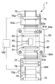
- FIG. 1 is a diagram illustrating a configuration of a simultaneous molding and decorating apparatus used in a simultaneous molding and decorating system according to an embodiment of the present invention.
- 2 is a cross-sectional view taken along II-II in FIG.
- FIG. 3 is a plan view showing an example of a decorative sheet showing a state before inspection used in the simultaneous molding and decorating apparatus shown in FIG.
- FIG. 4 is a diagram illustrating a configuration of an inspection apparatus used in the simultaneous molding decoration system according to the embodiment of the present invention.
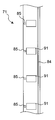
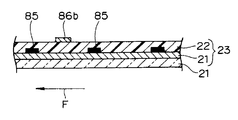
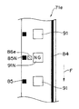
- FIG. 5A is a plan view showing a first example of a decorative sheet provided with a defect mark by an inspection apparatus;
- FIG. 5B is a sectional view taken along line BB in FIG. 5A.
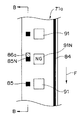
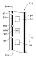
- FIG. 6A is a plan view showing a second embodiment of the decorative sheet to which the defect mark is given by the inspection apparatus; 6B is a cross-sectional view taken along line BB in FIG. 6A.
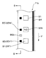
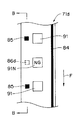
- FIG. 7A is a plan view showing a third example of the decorative sheet to which the defect mark is given by the inspection apparatus; FIG. 7B is a cross-sectional view taken along line BB in FIG. 7A.
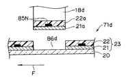
- FIG. 8A is a plan view showing a fourth example of a decorative sheet to which a defect mark is given by an inspection apparatus; 8B is a cross-sectional view taken along line BB in FIG. 8A.
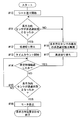
- FIG. 9 is a flowchart showing a skip operation when the decorative sheet shown in FIG. 5A is used.
- FIG. 10 is a flowchart showing a skip operation when the decorative sheet shown in FIG. 6A is used.
- FIG. 11 is a flowchart showing a skip operation when the decorative sheet shown in FIG. 7A is used,
- FIG. 12 is a flowchart showing the skip operation when the decorative sheet shown in FIG. 8A is used.
- FIG. 13 is a plan view showing a modification of the decorative sheet shown in FIG. 5A.
- the simultaneous molding decoration system includes a simultaneous molding decoration device that performs simultaneous molding decoration and an inspection device that inspects a decorative sheet used in the simultaneous molding device.
- the molding simultaneous decorating apparatus 1 continuously feeds a roll-shaped decorating sheet 71 between molds (fixed mold and movable mold) according to control by the control unit 100, and places the decorating sheet 71 in the mold. It is an apparatus for decorating a resin molded product by injecting molten resin in a sandwiched state and transferring a pattern attached to the surface of the decorative sheet 71 to the surface of the resin molded product.
- the inspection apparatus 10 see FIG. 4 inspects scratches, pinholes, and the like as will be described later. The one with a defect mark corresponding to the pattern is used.
- the simultaneous molding and decorating apparatus 1 includes a fixed plate 32 fixed on the frame 31 and a movable plate 34 that slides and moves on a tie bar 33 attached to the fixed plate 32.
- the movable platen 34 is supported by a roller (not shown) so that the frame can move.
- a fixed mold 36 is attached to the fixed platen 32.
- the fixed die 36 has a convex portion 36a on its parting surface side.
- the simultaneous molding and decorating apparatus 1 is configured such that molten resin can be injected from the injection nozzle 39 into the fixed mold 36.
- a movable mold 40 is attached to the movable platen 34.
- the movable mold 40 has a concave portion 40 a corresponding to the convex portion 36 a of the fixed mold 36.
- the movable mold 40 is provided with sheet clamps 80 and 81 for bringing the decorative sheet 71 into close contact with the mold.
- the fixed mold 36 is provided with a recess (not shown) so as not to interfere with the sheet clamps 80 and 81. Thus, when the movable mold 40 and the fixed mold 36 are closed, the sheet clamps 80 and 81 are avoided into the recesses.
- the upstream frame 60a and the downstream frame 60b are attached to the movable platen 34 so as to be movable in the horizontal direction.
- the upstream frame 60a and the downstream frame 60b can align the decorative sheet 71 in the longitudinal direction by feeding the decorative sheet 71 by an arbitrary feed amount. Further, the upstream frame 60a and the downstream frame 60b can be aligned in the width direction of the decorative sheet 71 by moving in the horizontal direction. That is, the upstream frame 60a and the downstream frame 60b function as a decorative sheet supply unit.
- the upstream frame 60a and the downstream frame 60b are guided by guides 62a and 62b with respect to guide rails 61a and 61b attached to the movable platen 34. As the guides 62a and 62b, direct acting slide bearings can be used.
- the upstream frame 60a and the downstream frame 60b can be independently moved in the horizontal direction by a width direction moving device (not shown) provided corresponding to each.
- Each of the width direction moving devices is configured such that a ball screw can be rotated at a predetermined rotational speed by, for example, a motor, a pulley, a belt, and the like, and the ball screw includes a nut attached to the upstream frame 60a and the downstream frame 60b. I'm engaged. Accordingly, the ball screw rotates by rotating the motor, and thereby the upstream frame 60a and the downstream frame 60b move in the horizontal direction.
- a sheet supply roller 69 is provided on the upstream frame 60a.
- the sheet supply roller 69 is configured to rotate by driving of the upstream motor 76a to unwind the decorative sheet 71.
- the upstream sheet guide rollers 72 and 78 guide the decorative sheet 71 unwound from the sheet supply roller 69 in the vertical direction so as to be positioned on the surface of the movable mold 40.
- the upstream sheet guide rollers 72 and 78 are not limited to two, and an arbitrary number can be provided.
- a powder clutch (not shown) may be provided on the reel shaft around which the decorative sheet 71 is wound.
- a sheet take-up roller 70 is provided on the downstream frame 60b.
- the sheet take-up roller 70 is configured to take up the decorative sheet 71 located on the surface of the movable mold 40.
- the sheet take-up roller 70 is provided with a motor 76b composed of a DC servo motor for driving the reel in order to apply an appropriate tension to the supplied decorative sheet 71.
- the downstream frame 60b is provided with an arbitrary number of downstream sheet guide rollers 77, 78, and 75 for guiding the decorative sheet 71 that has passed over the cavity surface of the movable mold 40 to the sheet take-up roller 70. ing.
- Width sensors 82a and 82b are provided in the upper and lower sides of the movable mold 40 in the supply direction of the decorative sheet 71, respectively.
- the movable mold 40 is provided with a longitudinal sensor 83 embedded therein. Since the longitudinal direction sensor 83 is embedded in the movable mold 40 and placed, the pattern of the decorative sheet 71 and the position of the longitudinal direction sensor 83 are close to each other, so that the alignment accuracy can be improved.
- the decorative sheet 71 is supplied vertically downward from the sheet supply roller 69, is guided by the upstream sheet guide rollers 72, 78, passes over the cavity surface of the movable mold 40, and the downstream sheet guide rollers 77, 78, Guided by 75, the sheet is wound around the sheet winding roller 70.
- the supply of the decorating sheet 71 is driven and controlled so that the pattern 91 formed on the decorating sheet 71 is positioned at a predetermined position with respect to the concave portion 40a of the movable mold 40 at the time of positioning.
- the control unit 100 controls driving of the sheet supply roller 69, the sheet take-up roller 70, the width direction moving device of the upstream frame 60a, and the width direction moving device of the downstream frame 60b. Is done.
- the positioning operation of the decorating sheet 71 is performed based on the detection results of the width direction sensors 82a and 82b and the longitudinal direction sensor 83 as will be described later, and then the operation of injecting the molten resin. Is done.
- the design of the decorating sheet 71 is in a state where it is arranged at a position corresponding to the cavity of the fixed mold 36 and the movable mold 40.
- the movable platen 34 is moved to perform a mold closing operation, and a pattern on the decorating sheet 71 is transferred simultaneously with molding. After cooling the molded product, the mold is opened and the molded product is taken out. This completes one cycle of operation.
- FIG. 3 shows the configuration of the decorative sheet used in this embodiment.
- the decorative sheet 71 shown in FIG. 3 is in a state where the inspection process described later has not been completed.
- the decorative sheet 71 includes a transparent base sheet 20 and a transfer layer 23 (see FIG. 5B) provided on the surface of the base sheet 20.
- the transfer layer 23 is formed by laminating a release layer 21, a design layer, an adhesive layer 22, and the like.
- the pattern layer includes a plurality of patterns 91 formed at regular intervals, a longitudinal mark 85 (also referred to as an eye mark) formed from each pattern 91 in a dot shape for each pattern 91 at regular intervals, and from each pattern 91.
- a width direction mark 84 (also referred to as a flow line) is provided in the vicinity of one end in the width direction of the decorative sheet 71 at regular intervals.
- the longitudinal direction mark 85 and the width direction mark 84 are position detection marks, and are attached at the same time when the pattern 91 is printed.
- the width direction sensors 82a and 82b and the length direction sensor 83 are a width direction mark 84 and a length direction mark 85 provided on the decorative sheet 71, and defect marks 86a, 86b and 86c attached in the inspection process described later (FIG. 5A). , 6A, 7A).
- the width direction sensors 82 a and 82 b and the longitudinal direction sensor 83 detect the positions of the decorative sheet 71 in the longitudinal direction and the width direction. Further, the width direction sensors 82a, 82b and the longitudinal direction sensor 83 read the defect marks 86a, 86b, 86c, and detect a pattern 91N having a defect.
- the width direction sensors 82a and 82b and the longitudinal direction sensor 83 are configured so that the attachment positions can be finely adjusted.
- FIG. 4 is a diagram illustrating a schematic configuration of an inspection apparatus that performs an inspection process of a decorative sheet.
- the inspection apparatus 10 is an apparatus that inspects the roll-shaped decorative sheet 71 on which the transfer layer 23 is printed by a gravure printing apparatus (not shown).
- the effective width of the decorative sheet 71 that can be inspected is 600 mm
- the defect detection size is 30 ⁇ m
- the feeding speed of the decorative sheet 71 is 10 to 40 m / min.
- the decorative sheet 71 to be inspected is attached to the delivery roller 11.
- the feed roller 11 is controlled to be driven by a torque motor 11a, and is controlled so as to send a decorative sheet 71 wound up by driving a take-up roller 12 described later with a predetermined tension.
- the winding roller 12 is controlled with respect to its driving amount and driving torque, and the inspection device 10 is configured to be able to detect the feeding amount of the decorative sheet 71 and the like.
- the decorative sheet 71 fed from the feed roller 11 is sent to the guide roller 19 via the dancer roller 13a and the sheet pressing rollers 16a and 17a.
- the sheet pressing roller 17a is connected to an air cylinder (not shown) that can move up and down. By this vertical movement of the air cylinder, the clamping force of the decorative sheet 71 between the sheet pressing roller 17a and the sheet pressing roller 16a can be adjusted. Thereby, the feeding of the decorating sheet 71 can be ensured.
- the guide roller 19 is composed of three rollers arranged almost horizontally, and guides the decorative sheet 71 in the horizontal direction.
- the decorative sheet 71 conveyed in the area where the guide roller 19 is disposed is inspected by the line sensor unit 15 provided above the guide roller 19.
- the line sensor unit 15 includes two sensors for measuring transmitted light and reflected light.
- a transmitted light source 14 a and a reflected light source 14 b are provided as light sources for inspection by the line sensor unit 15.
- a defect in the transfer layer 23 can be optically determined by inspecting an image captured by each line sensor unit 15 with a control calculation unit (not shown).
- a defect mark imparting section 18 is provided on the downstream side of the line sensor unit 15.
- the defect mark providing unit 18 can employ various configurations according to marks to be added as defect marks to be described later.
- Specific examples of the defect mark applying unit 18 include an inkjet unit and a laser marker for printing on the surface of the decorative sheet 71, a removal unit for partially removing the transfer layer 23 of the decorative sheet 71, and the like. Can be used.
- the decorative sheet 71 guided by the guide roller 19 is guided by the sheet pressing rollers 16b and 17b.
- the sheet pressing roller 17b is connected to an air cylinder (not shown) that can move up and down. By this vertical movement of the air cylinder, the clamping force of the decorative sheet 71 between the sheet pressing roller 17a and the sheet pressing roller 16b can be adjusted. Thereby, the feeding operation of the decorative sheet 71 can be performed reliably.
- a dancer roller 13b is provided on the downstream side of the sheet pressing rollers 16b and 17b.
- the decorative sheet 71 that has passed between the sheet pressing rollers 16b and 17b is guided by the dancer roller 13b and wound around the winding roller 12.
- the take-up roller 12 is provided with a torque motor 12a. By controlling the drive of the torque motor 12a, the winding roller 12 can wind up the decorative sheet 71 in a state where a predetermined tension is applied to the decorative sheet 71.
- the defect mark applying unit 18 adds a longitudinal mark 85N (see FIG. 5A) corresponding to the pattern 91N of the transfer layer 23 having a defect determined by the line sensor unit 15 in a form different from the non-defective longitudinal mark 85. It is given to the decorative sheet 71.
- the defect mark imparting unit 18 adds or deletes the longitudinal direction mark 85 to a specific location on the decorating sheet 71 in accordance with the conveyance timing of the decorating sheet 71.
- the detailed configuration of the defect mark applying unit 18 will be described later.
- the control of the defect mark is performed by a control unit of the inspection apparatus 10 (not shown).
- FIG. 5A is a plan view showing a first example of a decorative sheet provided with a defect mark by an inspection apparatus.
- FIG. 5B is a cross-sectional view taken along line BB in FIG. 5A. In addition, FIG. 5B has reduced and illustrated the scale of the decorating sheet in the longitudinal direction.
- the decorative sheet 71a is provided with a width direction mark 84, a longitudinal direction mark 85, and patterns 91 and 91N. These marks 84 and 85 and the patterns 91 and 91N are respectively attached to the transfer layer 23 provided on the surface of the base sheet 20, as shown in FIG. 5B.
- the transfer layer 23 includes a release layer 21 provided on the surface of the base sheet 20 and an adhesive layer 22 provided on the upper surfaces of the design layers 84, 85, 91.
- the arrow F has shown the supply direction in which the decorating sheet
- a release layer (not shown) may be formed on the entire surface before the transfer layer 23 is provided on the base sheet 20.
- the design layers 84, 85, and 91 are layers for expressing the design 91, the longitudinal direction mark 85, the width direction mark 84, and the like, and are provided on the surface of the release layer 21.
- the pattern layers 84, 85, 91 are formed of a metal thin film layer or the like applied on the release layer 72 by printing using ink, sputtering, or the like.
- an anchor layer (not shown).
- the adhesive layer 22 is a layer for adhering each layer to the surface of the resin molded product.
- the defect mark 86a is a mark given by the defect mark giving unit 18 of the inspection apparatus 10 shown in FIG.
- the defect mark 86a is printed continuously to the longitudinal direction mark 85N on the downstream side in the supply direction F of the longitudinal direction mark 85N corresponding to the defective pattern 91N.
- the surface on which the defect mark 86 a is printed is the surface of the transfer layer 23.
- an ink jet unit or the like can be suitably used as the defect mark applying unit 18 of the inspection apparatus 10 according to the first embodiment.
- FIG. 6A is a plan view showing a second example of the decorative sheet to which the defect mark is given by the inspection apparatus.
- 6B is a cross-sectional view taken along line BB in FIG. 6A.
- FIG. 6B illustrates the decorative sheet in a reduced scale in the longitudinal direction.
- the decorative sheet 71b is provided with a width direction mark 84, a longitudinal direction mark 85, and patterns 91 and 91N. These marks 84 and 85 and the patterns 91 and 91N are respectively attached to the transfer layer 23 provided on the surface of the base sheet 20, as shown in FIG. 6B.
- the layer structure of the decorating sheet 71b is the same as that of the decorating sheet 71a of 1st Example, it abbreviate
- the defect mark 86b is a mark given by the defect mark giving unit 18 of the inspection apparatus 10 shown in FIG.
- a defect mark 86b is printed at an intermediate position with respect to the longitudinal direction mark 85N corresponding to the defect pattern 91N.
- the surface on which the defect mark 86 b is printed is the surface of the transfer layer 23.
- an ink jet unit or the like can be suitably used as the defect mark applying unit 18 of the inspection apparatus 10 according to the second embodiment.
- FIG. 7A is a plan view showing a third example of the decorative sheet to which the defect mark is given by the inspection apparatus.
- FIG. 7B is a cross-sectional view taken along line BB in FIG. 7A.
- FIG. 7B has reduced and illustrated the scale of the decorating sheet in the longitudinal direction.
- a decorative sheet 71c is provided with a width direction mark 84, a longitudinal direction mark 85c, and patterns 91 and 91N. These marks 84 and 85 and the patterns 91 and 91N are respectively attached to the transfer layer 23 provided on the surface of the base sheet 20, as shown in FIG. 7B.
- the layer structure of the decorating sheet 71c is the same as that of the decorating sheet 71a of 1st Example, it abbreviate
- the longitudinal direction mark 85c is intermittently formed in a strip shape. Further, positions 87 and 87N at which the strip-like longitudinal direction mark 85c is interrupted (hereinafter referred to as intermittent positions) 87 and 87N are provided corresponding to the patterns 91 and 91N. That is, in the third embodiment, the simultaneous molding and decorating apparatus 1 detects the intermittent positions 87 and 87N of the longitudinal mark 85c using the longitudinal sensor 83, thereby aligning the decorating sheet 71c in the longitudinal direction. I do.
- the defect mark 86c is a mark given by the defect mark giving unit 18 of the inspection apparatus 10 shown in FIG.
- the defect mark 86c is printed at the intermittent position 87N of the longitudinal direction mark 85c corresponding to the defect pattern 91N.
- the gap at the intermittent position 87N is filled and the adjacent longitudinal direction marks 85c and 85c are connected via the intermittent position 87N.
- the surface on which the defect mark 86 c is printed is the surface of the transfer layer 23.
- an ink jet unit or the like can be suitably used as the defect mark applying unit 18 of the inspection apparatus 10 according to the third embodiment.
- FIG. 8A is a plan view showing a fourth example of the decorative sheet to which the defect mark is given by the inspection apparatus.
- 8B is a cross-sectional view taken along line BB in FIG. 8A.
- FIG. 8B has reduced and illustrated the scale of the decorating sheet in the longitudinal direction.
- the decorative sheet 71d is provided with a width direction mark 84, a longitudinal direction mark 85, and patterns 91 and 91N. These marks 84 and 85 and the patterns 91 and 91N are respectively attached to the transfer layer 23 provided on the surface of the base sheet 20, as shown in FIG. 8B.
- the layer structure of the decorating sheet 71d is the same as that of the decorating sheet 71a of 1st Example, it abbreviate
- the defect mark 86d is a mark given by the defect mark giving unit 18 of the inspection apparatus 10 shown in FIG.
- the defect mark 86d is given by removing the longitudinal mark 85N corresponding to the defect pattern 91N. That is, as shown in FIG. 8B, the longitudinal mark 85N corresponding to the defective pattern 91N is removed by removing the region of the transfer layer 23 including the longitudinal mark 85N corresponding to the defective pattern 91N. This prevents the longitudinal sensor 83 from detecting the longitudinal mark 85N when aligning the decorative sheet 71d in the longitudinal direction, as will be described later.
- an adhesive unit for removing the transfer layer 23 can be suitably used as the defect mark imparting section 18 of the inspection apparatus 10 according to the fourth embodiment. The adhesive unit is brought into contact with the transfer layer 23 from which the head 18d is removed, and the transfer layer 23 is transferred to the head 18d side, thereby removing the transfer layer 23 from the decorative sheet 71d.
- the positioning operation of the decorative sheet in the simultaneous molding and decorating apparatus shown in FIG. 1 will be described.
- subjected to the decorating sheet 71 is demonstrated.
- seat 71 is demonstrated.
- the motors 76a and 76b rotate.
- the speed is switched to low speed.
- the feeding speed of the decorating sheet 71 becomes slow.
- the feeding speed of the decorating sheet 71 at low speed can be, for example, about 1/20 of the feeding speed of the decorating sheet 71 at high speed.
- the timing of switching from high-speed feeding to low-speed feeding of the decorative sheet 71 may be controlled according to the feed amount of the decorative sheet 71 instead of the detection timing of the longitudinal mark 85 of the longitudinal sensor 83. . That is, since the decorative sheet 71 according to the present embodiment does not perform cutting and pasting for removing defective patterns as in the conventional example, the interval between the longitudinal marks 85 and 85 that are adjacent to each other is determined when the decorative sheet 17 is manufactured. Has not changed since. Therefore, since the intervals of the longitudinal direction marks 85 are all constant, even when the switching timing from the high speed feed to the low speed feed is controlled based on the feed amount of the decorative sheet 71, the accuracy is not lowered. .
- the motors 76a and 76b are at the timing when the longitudinal sensor 83 no longer detects the longitudinal mark 85 (that is, when the longitudinal sensor 83 switches between the transmissive state and the non-transmissive state). Stops, and the feeding operation of the decorative sheet 71 is stopped.
- the motor 76a provided in the upstream frame 60a in order to stabilize the rotation speed, it is preferable to use a servo motor and control the rotation speed by feedback control using a tachometer or an encoder.
- the decorative sheet 71 After positioning the decorative sheet 71 in the longitudinal direction as described above, the decorative sheet 71 is positioned in the width direction.
- the decorating sheet 71 arranged on the cavity surface of the movable mold 40 is moved in the horizontal direction. Accordingly, when one end of the width direction mark 84 is detected by the width direction sensors 82a and 82b, the moving speed of the decorative sheet 71 is decreased. Thereafter, the decoration sheet 71 is moved at the timing when the other end of the width direction mark 84 is detected by the width direction sensors 82a and 82b or after the decoration sheet 71 is moved in the horizontal direction by a predetermined length. Stop.
- the movement of the decorative sheet 71 in the horizontal direction is small, the movement of the decorative sheet 71 is immediately stopped when one end of the width direction mark 84 is detected by the width direction sensors 82a and 82b. Good.
- the two sensors of the width direction sensors 82a and 82b are used to adjust the inclination of the decorative sheet 71 with respect to the vertical direction.
- the defect pattern skipping operation is performed differently depending on the form of the defect mark attached to the decorative sheet, as shown in FIGS. 5A to 8A.
- the defect pattern skipping operation will be described for each decorative sheet according to each of the above embodiments.
- the skip operation refers to an operation from the completion of the molding operation of one cycle before the defective pattern to the end of the alignment of the next good pattern in the longitudinal direction.
- FIG. 9 is a flowchart showing the skip operation when the decorative sheet shown in FIG. 5A is used.
- the skip operation to be set in the simultaneous molding and decorating apparatus when this decorating sheet 71a is used is as follows. First, the feeding operation of the decorative sheet 71a is started (# 10). At this time, the feeding speed of the decorative sheet 71a is high. When the decorative sheet 71a is sent in the longitudinal direction, the longitudinal sensor 83 is shielded by the longitudinal mark 85 and switches from the transmissive state (no in # 11) to the non-transmissive state (yes in # 11). At this timing, the feeding speed of the decorative sheet 71a is switched to a low speed (# 12), and a timer (not shown) starts time counting (# 13).
- the longitudinal sensor 83 When the longitudinal sensor 83 is switched from the non-transmissive state to the transmissive state before the time count elapses (no in # 14) while the feeding speed of the decorative sheet 71a is low (that is, the longitudinal direction sensor) If the time during which 83 is shielded is shorter than the predetermined time: (Yes in # 15), the motor 76 is stopped (# 16). Thereby, the alignment of the longitudinal direction of the decorating sheet 71a is completed.
- a defect mark 86a is attached continuously (adjacent) to the longitudinal mark 85.
- the motor 76 is switched to high speed driving, and the feeding speed of the decorating sheet 71a is increased (# 17).
- the defect sensor 86a passes through the longitudinal sensor 83 so that the longitudinal sensor 83 becomes non-transmissive, but this detection signal is ignored (# 18). That is, the first non-transmission state of the longitudinal sensor 83 is ignored.
- the decorative sheet 71a is fed at a high speed until the longitudinal sensor 83 detects a non-transmissive state (yes in # 11).
- the above operation is repeated until the alignment of the decorative sheet 71a in the longitudinal direction is completed.
- the timer count is started at the timing when the feeding speed of the decorative sheet 71a is switched from high speed to low speed. Processing triggers can be reduced. Thereby, the skip operation can be performed with easy processing.
- the presence or absence of the defect mark 86a may be determined according to the feed amount of the decorative sheet 71a instead of performing time counting. That is, the feeding amount of the decorative sheet 71a after the longitudinal sensor 83 is in the non-transmissive state in # 11 is counted, and whether or not the decorative sheet 71a has moved a predetermined distance when the longitudinal sensor 83 is in the non-transmissive state. Whether or not the defect mark 86a is present can be determined.
- FIG. 10 is a flowchart showing a skip operation when the decorative sheet shown in FIG. 6A is used.
- the skip operation to be set in the simultaneous molding and decorating apparatus when this decorating sheet 71b is used is as follows. First, the feeding operation of the decorative sheet 71b is started (# 20). At this time, the feeding speed of the decorative sheet 71b is high as described above. At the same time as the feeding operation of the decorative sheet 71b is started, a timer (not shown) starts time counting (# 21).
- the longitudinal sensor 83 detects the longitudinal mark 85 and switches from the transmissive state to the non-transmissive state (Yes in # 22). It is determined whether or not the switching timing is after a predetermined time has elapsed from the start of the time count of the timer. If the predetermined time has elapsed (Yes in # 23), the decorative sheet 71b is used as described above. Is switched to a low speed (# 24).
- the longitudinal sensor 83 when the longitudinal sensor 83 is switched from the transmission state to the non-transmission state before the predetermined time has elapsed from the start of the time count during the high-speed feeding of the decorative sheet 71b (no in # 23), they are adjacent to each other. It is determined that the longitudinal sensor 83 detects the defect mark 86b provided between the longitudinal marks 85 and 85 to be detected. In this case, the high-speed feeding of the decorative sheet 71b is continued. In the middle of high-speed feeding of the decorative sheet 71b, the defect sensor 86b passes through the longitudinal sensor 83 so that the longitudinal sensor 83 becomes non-transmissive, but this detection signal is ignored (# 28). That is, the first non-transmission state of the longitudinal sensor 83 is ignored.
- the decorative sheet 71b is fed at a high speed until the longitudinal sensor 83 detects a non-transmissive state (yes in # 22).
- the above operation is repeated until the alignment of the decorative sheet 71b in the longitudinal direction is completed.
- the timer count is started at the timing when the feeding speed of the decorative sheet 71a is switched from high speed to low speed. For this reason, the trigger of a process increases.
- the control for providing the defect mark 86b of the inspection apparatus 10 can be simplified.
- FIG. 11 is a flowchart showing the skip operation when the decorative sheet shown in FIG. 7A is used.
- the skip operation to be set in the simultaneous molding and decorating apparatus when this decorating sheet 71c is used is as follows. First, the feeding operation of the decorative sheet 71c is started (# 30). The feeding speed of the decorative sheet 71c at this time is high as described above. Since the longitudinal mark 85c of the decorative sheet 71c is configured in a band shape provided intermittently, the longitudinal sensor 83 is in a non-transmissive state at a timing when the pattern 91 is not detected.
- the longitudinal sensor 83 detects the intermittent position 87 of the longitudinal mark 85c and switches from the non-transmissive state to the transmissive state (Yes in # 31).
- a defect mark 86c is given to the intermittent position 87N corresponding to the defective pattern 91N.
- the longitudinal sensor 83 cannot detect the intermittent position 87 at the position corresponding to the defective pattern 91N. Therefore, when the longitudinal sensor 83 detects the transmission state, the pattern 91 corresponding to the detected position is not the defective pattern 91N.
- the feeding speed of the decorative sheet 71c is switched to the low speed as described above (# 32).
- the decorative sheet 71c is sent at a low speed, and when the longitudinal sensor 83 is switched from the transmission state to the non-transmission state (yes in # 33), the motor 76 is stopped (# 34). Thereby, the alignment of the longitudinal direction of the decorating sheet 71c is completed.
- a defect pattern can be obtained by an easy control operation without performing the time count by devising the shape of the longitudinal direction mark 85c. And a good pattern are discriminated. Thereby, the skip operation can be performed with easy processing. Also, the application of the defect mark 86c by the inspection apparatus 10 can be realized with a simple configuration such as an ink jet unit.
- FIG. 12 is a flowchart showing a skip operation when the decorative sheet shown in FIG. 8A is used.
- the skip operation to be set in the simultaneous molding and decorating apparatus when this decorating sheet 71d is used is as follows. First, the feeding operation of the decorating sheet 71d is started (# 40). At this time, the feeding speed of the decorating sheet 71d is high as described above.
- the longitudinal direction mark 85 of the decorating sheet 71d is attached only to the good pattern 91, and the longitudinal direction mark 85 attached to the defective pattern 91N before the inspection by the inspection apparatus 10 is removed. Therefore, the longitudinal sensor 85 does not detect the longitudinal mark 85 because the longitudinal mark 85 is not provided at the position corresponding to the defective pattern 91N. Therefore, when the longitudinal sensor 83 detects the non-transmission state, the pattern 91 corresponding to the detection position is not the defective pattern 91N.
- the longitudinal sensor 83 When the decorating sheet 71d is sent in the longitudinal direction, the longitudinal sensor 83 is shielded by the longitudinal mark 85 and switches from the transmissive state to the non-transmissive state (Yes in # 41). At the timing when the longitudinal sensor 83 is switched from the transmissive state to the non-transmissive state, the feeding speed of the decorative sheet 71d is switched to the low speed as described above (# 42).
- the longitudinal direction mark 85 corresponding to the defective pattern 91N is removed.
- the process for the alignment operation can be used as it is without particularly requiring control for the skip operation in the simultaneous molding and decorating apparatus 1.
- the longitudinal length corresponding to the defect pattern 91N detected at the inspection stage of the decorative sheet 71 Since the defect mark is given to the direction mark, it is possible to form the molded product by skipping the defect pattern 91N during the simultaneous decoration. Therefore, it is not necessary to cut and paste the decorative sheet 71 at the inspection stage of the decorative sheet 71, and a good pattern is not wasted. Therefore, it is possible to prevent the decorative sheet from being wasted and to form a defective molded product, and the production yield of a good molded product can be improved.
- the longitudinal sensor 83 is used as a sensor for detecting the defect marks 86a to 86d in the simultaneous molding and decorating apparatus 1, but an independent sensor for detecting the defect marks 86a to 86d is further provided. It may be configured. In this case, it is preferable that the positional relationship between the longitudinal direction sensor 83 and the defect mark detection sensor be a different position in the width direction of the decorative sheet 71e as shown in FIG.
- the patterns 91 and 91N are determined depending on whether or not the sensor for inspecting the defect mark 86e is in a transmissive state. It may be determined whether or not to skip.
- the defect marks 86a to 86e are attached to the patterns determined to be the defective pattern 91N by the inspection apparatus 10.
- the defect pattern 91N can be visually determined.
- a defect indication may be attached.
- the defect display include “NG characters” and cross marks.
- the defect display is attached to any surface of the decorative sheet 71. However, when it is attached to the side where the transfer layer 23 is provided, the skip operation seems to have malfunctioned. In this case, the defect indication is transferred as it is to the molded product at the time of simultaneous decoration. Therefore, in the defect inspection of the molded product after molding, there is an effect that the defect inspection can be easily performed by finding the defect display.
- inspection apparatus 10 were comprised as an independent apparatus as an apparatus which comprises a shaping
- the line sensor unit 15 and the defect mark applying part 18 such as an ink jet unit may be provided on the upstream frame 60a.
Landscapes
- Engineering & Computer Science (AREA)
- Manufacturing & Machinery (AREA)
- Mechanical Engineering (AREA)
- Injection Moulding Of Plastics Or The Like (AREA)
Abstract
本発明の成形同時加飾装置は、加飾シート中に含まれる欠陥を有する絵柄を用いて成形同時加飾を行うことを防止し、その結果として加飾成形品の歩留まりを向上させるため、検査装置10で加飾シート71の絵柄91に欠陥があるか否かを光学的に検査すると共に、欠陥絵柄91Nに対応して欠陥マーク86aを付与された加飾シート71aを用い、前記欠陥絵柄を用いて成形同時転写しないように、成形同時加飾装置1で欠陥マークに基づいて欠陥絵柄をスキップして位置あわせしないようにする。
Description
本発明は、樹脂成形品に加飾シートを用いて加飾を行う成形同時加飾装置に用いられる加飾シートの位置合わせ及び欠陥管理技術に関する。
従来、樹脂成形品の表面を装飾する方法として、転写材などを基体シートの表面に形成した加飾シートを利用した成形同時加飾法がある。
成形同時加飾法とは、基体シート上に、転写層を形成した加飾シートを成形金型内に挟み込み、金型内に溶融樹脂を射出し、冷却して樹脂成形品を得るのと同時に成形品表面に加飾シートを接着した後、基体シートを剥離して、被転写物面に転写層を転移して装飾を行う方法である。成形同時加飾法は、印刷法によって直接図柄を形成することが困難な形状の成形品であっても図柄を形成することができるという特徴を有する。
ところで、成形同時加飾に用いられる加飾シートは、通常、ポリカーボネートなどの基体シートの表面にグラビア印刷で剥離層、図柄層、接着層などを含む転写層が印刷された長尺状のロールで構成されている。
しかし、ロール状の加飾シートに設けられた転写層には、グラビア印刷時あるいは巻き取り時等にスジやピンホールなどの微細欠陥が発生する場合がある。欠陥を有する転写層を用いて成形同時加飾すると、欠陥を有する成形品の発生につながるおそれがある。このため、成形同時加飾装置に用いられる加飾シートを予め検査し、欠陥を有する転写層(絵柄)を取り除くことが行われている。
加飾シートの検査は、通常印刷工程を終了し、ロール状に巻き取られた加飾シートを解きながら転写層を目視確認することによって行われている。転写層の一部に欠陥を見つけた場合には、当該欠陥部分を取り除くため、当該欠陥部分を含む加飾シートの一部を切断し、その後、テープなどで切断された2つのシートをつなぎ直す切り貼りが行われている。
しかし、加飾シートを目視で確認することは、その確認作業の手間が膨大である。また、テープなどで接続された加飾シートは、成形時の位置合わせなどを行い難い。その結果、成形工程において、不良品の原因となる2次不良が発生するおそれがある。
また、加飾シートの製造工程では、転写層の1つ1つの絵柄を確認するのではなく、加飾シートのロール全体を数メートル単位のブロックに分け、欠陥部分を有するブロック全体を除去することとなる。したがって、当該ブロックに欠陥を有しない絵柄が含まれていることもあり、加飾シートをムダに廃棄することが行われている。
したがって、本発明が解決しようとする技術的課題は、加飾シート中に含まれる欠陥を有する絵柄を用いて成形同時加飾を行うことを防止し、その結果として加飾成形品の歩留まりを向上させることができる成形同時加飾装置用の加飾シートを提供することである。
本発明は、上記技術的課題を解決するために、以下の構成の成形同時加飾装置、加飾シート、及び成形同時加飾システムを提供する。
本発明の第1態様によれば、基体シートの表面に複数の良品絵柄及び欠陥絵柄を含む転写層が付され、前記欠陥絵柄に対応して設けられた欠陥マークと、幅方向マークと、長手方向マークとが付与されている加飾シートを用い、前記加飾シートを前記金型に対して位置合わせした状態で型閉じして溶融樹脂を射出し、前記転写層を前記溶融樹脂が固化した成形品の表面に転写させる成形同時加飾装置であって、
前記加飾シートを前記金型の間に間欠的に供給する加飾シート供給部と、
前記長手方向マークと前記幅方向マークと前記欠陥マークを検出するマーク検出センサと、
前記マーク検出センサによる検出結果に基づいて、前記加飾シートの絵柄を前記金型に対して位置合わせするように前記加飾シート供給部を駆動制御する駆動制御部と、
を備え、
前記駆動制御部は、
前記マーク検出センサにより前記欠陥マークを検出したとき、前記欠陥マークに対応する絵柄をスキップして前記位置合わせしないように前記加飾シート供給部を駆動制御する、成形同時加飾装置を提供する。
前記加飾シートを前記金型の間に間欠的に供給する加飾シート供給部と、
前記長手方向マークと前記幅方向マークと前記欠陥マークを検出するマーク検出センサと、
前記マーク検出センサによる検出結果に基づいて、前記加飾シートの絵柄を前記金型に対して位置合わせするように前記加飾シート供給部を駆動制御する駆動制御部と、
を備え、
前記駆動制御部は、
前記マーク検出センサにより前記欠陥マークを検出したとき、前記欠陥マークに対応する絵柄をスキップして前記位置合わせしないように前記加飾シート供給部を駆動制御する、成形同時加飾装置を提供する。
本発明の第2態様によれば、前記欠陥マークは、前記加飾シートの長手方向に対して前記長手方向マークと同列になるように設けられ、
前記マーク検出センサは、前記幅方向マークを検出する幅方向センサと、前記長手方向マーク及び前記欠陥マークを検出する長手方向センサと、を備える、第1態様の成形同時加飾装置を提供する。
前記マーク検出センサは、前記幅方向マークを検出する幅方向センサと、前記長手方向マーク及び前記欠陥マークを検出する長手方向センサと、を備える、第1態様の成形同時加飾装置を提供する。
本発明の第3態様によれば、前記欠陥マークは、前記加飾シートの長手方向に対して前記長手方向マークと同列になるように、前記欠陥絵柄に対応する長手方向マークの加飾シート供給方向下流側に連続して設けられ、
前記駆動制御部は、
前記長手方向センサが非透過状態である時間又は前記加飾シートの送り量が、予め決められた閾値よりも大きいか否かによって、前記欠陥マークの有無を検出する、第2態様の成形同時加飾装置を提供する。
前記駆動制御部は、
前記長手方向センサが非透過状態である時間又は前記加飾シートの送り量が、予め決められた閾値よりも大きいか否かによって、前記欠陥マークの有無を検出する、第2態様の成形同時加飾装置を提供する。
本発明の第4態様によれば、前記欠陥マークは、加飾シート供給方向に対して前記長手方向マークと同列になるように、前記欠陥絵柄に対応する長手方向マークと前記欠陥絵柄の1つ前の絵柄に対応する長手方向マークとの間に設けられ、
前記駆動制御部は、
前記長手方向センサが透過状態である時間又は前記加飾シートの送り量が、予め決められた閾値よりも大きいか否かによって、前記欠陥マークの有無を検出する、第2態様の成形同時加飾装置を提供する。
前記駆動制御部は、
前記長手方向センサが透過状態である時間又は前記加飾シートの送り量が、予め決められた閾値よりも大きいか否かによって、前記欠陥マークの有無を検出する、第2態様の成形同時加飾装置を提供する。
本発明の第5態様によれば、金型に対して位置合わせした状態で型閉じして溶融樹脂を射出し、転写層を前記溶融樹脂が固化した成形品の表面に転写させる成形同時加飾装置に用いられる加飾シートであって、
基体シートの表面に複数の良品絵柄及び欠陥絵柄を含む転写層が付され、前記欠陥絵柄に対応して設けられた欠陥マークと、幅方向マークと、長手方向マークとが付与されている、加飾シートを提供する。
基体シートの表面に複数の良品絵柄及び欠陥絵柄を含む転写層が付され、前記欠陥絵柄に対応して設けられた欠陥マークと、幅方向マークと、長手方向マークとが付与されている、加飾シートを提供する。
本発明の第6態様によれば、前記幅方向マークは、前記加飾シートの幅方向一端近傍に前記加飾シートの長手方向に帯状に延在して設けられ、
前記長手方向マークは、前記それぞれの絵柄に対応して設けられ、
前記欠陥マークは、前記長手方向に対して前記長手方向マークと同列になるように設けられている、第5態様の加飾シートを提供する。
前記長手方向マークは、前記それぞれの絵柄に対応して設けられ、
前記欠陥マークは、前記長手方向に対して前記長手方向マークと同列になるように設けられている、第5態様の加飾シートを提供する。
本発明の第7態様によれば、前記欠陥マークは、前記欠陥絵柄に対応する長手方向マークの加飾シート供給方向下流側に連続して設けられている、第6態様の加飾シートを提供する。
本発明の第8態様によれば、前記欠陥マークは、前記欠陥絵柄に対応する長手方向マークと前記欠陥絵柄の1つ前の絵柄に対応する長手方向マークとの間に設けられている、第6態様の加飾シートを提供する。
本発明の第9態様によれば、前記幅方向マークは、前記加飾シートの幅方向一端近傍に前記長手方向に帯状に延在して設けられ、
前記長手方向マークは、前記それぞれの絵柄に対応して間隙が空くように間欠的な帯状に設けられ、
前記欠陥マークは、前記欠陥絵柄に対応する前記間隙を塗りつぶすように設けられている、第5態様の加飾シートを提供する。
前記長手方向マークは、前記それぞれの絵柄に対応して間隙が空くように間欠的な帯状に設けられ、
前記欠陥マークは、前記欠陥絵柄に対応する前記間隙を塗りつぶすように設けられている、第5態様の加飾シートを提供する。
本発明の第10態様によれば、検査装置と成形同時加飾装置とを備え、
前記検査装置により基体シートの表面に複数の絵柄を含む転写層が付され長手方向マークと幅方向マークとを有する加飾シートを前記それぞれの絵柄が欠陥を有するか否かを検査し、前記成形同時加飾装置により前記検査された加飾シートを金型の間に間欠的に供給し、前記加飾シートを前記長手方向マークと前記幅方向マークとに基づいて前記金型に対して位置合わせした状態で型閉じして溶融樹脂を射出し、前記転写層を前記溶融樹脂が固化した成形品の表面に転写させる成形同時加飾システムであって、
前記検査装置は、
前記加飾シートの絵柄が前記欠陥絵柄であるか否かを光学的に判断するセンサユニットと、
前記センサユニットにより前記欠陥絵柄であると判断された場合に、前記欠陥絵柄に対応して欠陥マークを付与する欠陥マーク付与部を有し、
前記成形同時加飾装置は、
前記加飾シートを供給して前記加飾シートを前記金型に対して位置合わせする加飾シート供給部と、
前記加飾シート供給部により、前記加飾シートを前記金型に対して位置合わせする前に前記欠陥マークを検出する欠陥マーク検出センサと、
前記欠陥マーク検出センサが前記欠陥マークを検出したとき、前記欠陥マークに対応する絵柄をスキップして前記位置合わせしないように前記加飾シート供給部を駆動制御する駆動制御部と、
を備える、成形同時加飾システムを提供する。
前記検査装置により基体シートの表面に複数の絵柄を含む転写層が付され長手方向マークと幅方向マークとを有する加飾シートを前記それぞれの絵柄が欠陥を有するか否かを検査し、前記成形同時加飾装置により前記検査された加飾シートを金型の間に間欠的に供給し、前記加飾シートを前記長手方向マークと前記幅方向マークとに基づいて前記金型に対して位置合わせした状態で型閉じして溶融樹脂を射出し、前記転写層を前記溶融樹脂が固化した成形品の表面に転写させる成形同時加飾システムであって、
前記検査装置は、
前記加飾シートの絵柄が前記欠陥絵柄であるか否かを光学的に判断するセンサユニットと、
前記センサユニットにより前記欠陥絵柄であると判断された場合に、前記欠陥絵柄に対応して欠陥マークを付与する欠陥マーク付与部を有し、
前記成形同時加飾装置は、
前記加飾シートを供給して前記加飾シートを前記金型に対して位置合わせする加飾シート供給部と、
前記加飾シート供給部により、前記加飾シートを前記金型に対して位置合わせする前に前記欠陥マークを検出する欠陥マーク検出センサと、
前記欠陥マーク検出センサが前記欠陥マークを検出したとき、前記欠陥マークに対応する絵柄をスキップして前記位置合わせしないように前記加飾シート供給部を駆動制御する駆動制御部と、
を備える、成形同時加飾システムを提供する。
本発明の第11態様によれば、前記欠陥マーク検出センサは、前記長手方向マークを検出する長手方向センサであり、
前記欠陥マーク付与部は、前記欠陥絵柄に対応する長手方向マークに対して前記欠陥マークを付与する、第10態様の成形同時加飾システムを提供する。
前記欠陥マーク付与部は、前記欠陥絵柄に対応する長手方向マークに対して前記欠陥マークを付与する、第10態様の成形同時加飾システムを提供する。
本発明の第12態様によれば、前記欠陥マーク付与部は、前記加飾シートに前記欠陥マークを印刷する印刷ユニットである、第10又は第11態様の成形同時加飾システムを提供する。
本発明の第13態様によれば、前記印刷ユニットは、前記欠陥絵柄に対応する長手方向マークの加飾シート供給方向下流側に、前記長手方向マークに連続して前記欠陥マークを印刷する、第12態様の成形同時加飾システムを提供する。
本発明の第14態様によれば、前記印刷ユニットは、前記欠陥絵柄に対応する前記長手方向マークと、前記欠陥絵柄の1つ前の絵柄に対応する前記長手方向マークとの間に前記欠陥付与マークを付す、第12態様の成形同時加飾システムを提供する。
本発明の第15態様によれば、前記印刷ユニットは、前記それぞれの絵柄に対応して間隙が空くように間欠的に帯状に設けられた前記長手方向マークの間に位置する前記欠陥絵柄に対応する間隙に、前記間隙を塗りつぶすように前記欠陥マークを印刷する、第12態様の成形同時加飾システムを提供する。
本発明の第16態様によれば、前記欠陥マーク付与部は、前記センサユニットにより前記欠陥絵柄であると判断された絵柄に対応する長手方向マークを除去する除去ユニットである、第10又は第11態様の成形同時加飾システムを提供する。
本発明の第17態様によれば、前記印刷ユニットは、前記欠陥マークとは別に欠陥表示を前記欠陥絵柄上に印刷する、第12態様の成形同時加飾システムを提供する。
本発明の第1態様によれば、前記欠陥絵柄に対応して欠陥マークを付与された加飾シートを用い、成形同時加飾装置で欠陥マークを基準としてスキップして位置合わせしないようにすることができるため、欠陥絵柄に基づいて成形品が成形されることがない。したがって、加飾シートの欠陥絵柄を取り除く手間を省力化すると共に、従前の欠陥絵柄の取り除き作業において発生した加飾シートの切り貼りによる不良の問題をなくすることができる。また、欠陥絵柄を除いて成形品が作成されるため、成形品の良品の製造歩留まりを向上させることができる。
本発明の第2態様によれば、欠陥マークと長手方向マークとを検出するセンサが1つでよいため、装置の簡略化を図ることができる。また、この構成をとった場合、センサが検出した信号において、欠陥マークと長手方向マークとの区別を付ける必要があるため、例えば、欠陥マーク及び長手方向マークとが光学的センサの光を遮蔽する遮蔽時間を用いて両者を区別することができる。
本発明の第5態様によれば、成形同時加飾装置で欠陥マークを基準としてスキップして位置合わせしないようにすることができるため、欠陥絵柄に基づいて成形品が成形されることがない。したがって、加飾シートの欠陥絵柄を取り除く手間を省力化すると共に、従前の欠陥絵柄の取り除き作業において発生した加飾シートの切り貼りによる不良の問題をなくすることができる。また、欠陥絵柄を除いて成形品が作成されるため、成形品の良品の製造歩留まりを向上させることができる。
本発明の第10態様によれば、検査装置で絵柄を光学的に検査すると共に、前記欠陥絵柄に対応して欠陥マークを付与された加飾シートを用い、成形同時加飾装置で欠陥マークを基準としてスキップして位置合わせしないようにすることができるため、欠陥絵柄に基づいて成形品が成形されることがない。したがって、加飾シートの欠陥絵柄を取り除く手間を省力化すると共に、従前の欠陥絵柄の取り除き作業において発生した加飾シートの切り貼りによる不良の問題をなくすることができる。また、欠陥絵柄を除いて成形品が作成されるため、成形品の良品の製造歩留まりを向上させることができる。
本発明の第11態様によれば、欠陥マークを検出するセンサと長手方向マークを検出するセンサを共用化することにより、装置の簡略化を図ることができる。
本発明のこれらと他の目的と特徴は、添付された図面についての好ましい実施の形態に関連した次の記述から明らかになる。この図面においては、
図1は、本発明の実施形態にかかる成形同時加飾システムに用いられる成形同時加飾装置の構成を示す図であり、
図2は、図1のII-IIに沿う断面図であり、
図3は、図1に示す成形同時加飾装置に用いられる検査前の状態を示す加飾シートの一実施例を示す平面図であり、
図4は、本発明の実施形態にかかる成形同時加飾システムに用いられる検査装置の構成を示す図であり、
図5Aは、検査装置により欠陥マークが付与された加飾シートの第1実施例を示す平面図であり、
図5Bは、図5AのB-B線での断面図であり、
図6Aは、検査装置により欠陥マークが付与された加飾シートの第2実施例を示す平面図であり、
図6Bは、図6AのB-B線での断面図であり、
図7Aは、検査装置により欠陥マークが付与された加飾シートの第3実施例を示す平面図であり、
図7Bは、図7AのB-B線での断面図であり、
図8Aは、検査装置により欠陥マークが付与された加飾シートの第4実施例を示す平面図であり、
図8Bは、図8AのB-B線での断面図であり、
図9は、図5Aに示す加飾シートを用いた場合のスキップ動作を示すフローチャートであり、
図10は、図6Aに示す加飾シートを用いた場合のスキップ動作を示すフローチャートであり、
図11は、図7Aに示す加飾シートを用いた場合のスキップ動作を示すフローチャートであり、
図12は、図8Aに示す加飾シートを用いた場合のスキップ動作を示すフローチャートであり、
図13は、図5Aに示す加飾シートの変形例を示す平面図である。
本発明の記述を続ける前に、添付図面において同じ部品については同じ参照符号を付している。
以下、本発明の一実施形態について、図面を参照しながら説明する。本実施形態にかかる成形同時加飾システムは、成形同時加飾を行う成形同時加飾装置と、成形同時加飾装置に用いられる加飾シートを検査する検査装置を備えている。
図1及び図2に、本発明の実施形態にかかる成形同時加飾装置の構成を示す。成形同時加飾装置1は、制御部100による制御に従い、ロール状の加飾シート71を連続的に金型(固定型、可動型)の間に送り込み、当該金型内に加飾シート71を挟んだ状態で溶融樹脂を射出して、加飾シート71の表面に付されている絵柄を樹脂成形品の表面に転写させることによって樹脂成形品を加飾する装置である。なお、本実施形態にかかる成形同時加飾装置1に用いられる加飾シート71としては、後述するように検査装置10(図4参照)によって絵柄のキズやピンホールなどの検査がされ、欠陥品の絵柄に対応して欠陥マークが付与された状態のものが用いられる。
成形同時加飾装置1は、フレーム31上に固定された固定盤32と、固定盤32に取り付けられたタイバー33上を摺動移動する可動盤34とを備えている。可動盤34は、そのフレームを図示しないローラによって移動可能に支持されている。
固定盤32には、固定型36が取り付けられている。固定型36は、そのパーティング面側に凸部36aを有している。成形同時加飾装置1は、この固定型36に、射出ノズル39から溶融樹脂を射出可能に構成されている。
可動盤34には、可動型40が取り付けられている。可動型40は、固定型36の凸部36aに対応した凹部40aを有している。可動型40には、加飾シート71を金型に密着させるためのシートクランプ80,81が設けられている。固定型36には、これらのシートクランプ80,81と干渉しないように、凹部(図示なし)が設けられている。これにより、可動型40と固定型36とを型閉じした際、シートクランプ80,81は、凹部内へ回避される。
また、可動盤34に対して、上流側フレーム60aと下流側フレーム60bとが水平方向に移動可能に取り付けられている。上流側フレーム60aと下流側フレーム60bとは、任意の送り量だけ加飾シート71を送ることにより、加飾シート71の長手方向の位置合わせを行うことができる。また、上流側フレーム60aと下流側フレーム60bとは、水平方向に移動することにより、加飾シート71の幅方向の位置合わせを行うことができる。すなわち、上流側フレーム60aと下流側フレーム60bとは、加飾シート供給部として機能する。上流側フレーム60aと下流側フレーム60bとは、可動盤34に取り付けられた案内レール61a,61bに対してガイド62a,62bによって案内されている。ガイド62a,62bとしては直動型スライドベアリングを使用することができる。
上流側フレーム60aと下流側フレーム60bは、それぞれに対応して設けられている図示しない幅方向移動装置によって、それぞれ独立に水平方向に移動させることができる。それぞれの幅方向移動装置は、例えば、モータ、プーリ,ベルトなどによってボールネジを所定の回転速度で回転可能に構成されており、このボールネジは上流側フレーム60aと下流側フレーム60bとに取り付けたナットと噛み合っている。したがって、モータを回転させることによりボールネジが回転し、これによって上流側フレーム60a及び下流側フレーム60bが水平方向に移動する。
上流側フレーム60aには、シート供給ローラ69が設けられている。シート供給ローラ69は、上流側モータ76aの駆動により回転して加飾シート71を巻き出すように構成されている。上流側シートガイドローラ72,78は、シート供給ローラ69から巻き出された加飾シート71を、可動型40の表面に位置するように鉛直方向に案内する。なお、上流側シートガイドローラ72,78は、2つに限られるものではなく、任意数を設けることができる。また、供給された加飾シート71に適切な張力を付与するため、加飾シート71を巻き取るリールの軸にパウダークラッチ(図示せず)を設けるように構成してもよい。
下流側フレーム60bには、シート巻取ローラ70が設けられている。シート巻取ローラ70は、可動型40の表面に位置する加飾シート71を巻き取るように構成されている。シート巻取ローラ70には、供給された加飾シート71に適切な張力を付与するため、リールの駆動にDCサーボモータで構成されるモータ76bが設けられている。また、下流側フレーム60bには、可動型40のキャビティ面上を通過した加飾シート71をシート巻取ローラ70に導くため、任意の数の下流側シートガイドローラ77,78,75が設けられている。
可動型40の上下には、それぞれ幅方向センサ82a,82bが、加飾シート71の供給方向に並べて設けられている。また、可動型40には、長手方向センサ83が埋め込まれた状態で設けられている。長手方向センサ83を可動型40内に埋め込んで配置することにより、加飾シート71の絵柄と長手方向センサ83の位置が近くなるので、位置合わせの精度を向上させることができる。
加飾シート71は、シート供給ローラ69から鉛直方向下向きに供給され、上流側シートガイドローラ72,78に案内されて可動型40のキャビティ面上を通過し、下流側シートガイドローラ77,78,75に案内されてシート巻取ローラ70に巻き取られる。
加飾シート71の供給は、位置決め時に、加飾シート71に形成された図柄91が可動型40の凹部40aに対して所定の位置に配置されるように、駆動制御される。加飾シート71の供給及び位置決めは、制御部100が、シート供給ローラ69、シート巻取ローラ70、上流側フレーム60aの幅方向移動装置、及び下流側フレーム60bの幅方向移動装置の駆動を制御することにより行われる。
成形同時加飾装置1においては、幅方向センサ82a,82bと長手方向センサ83の検出結果に基づいて、後述するように加飾シート71の位置決め動作が行われ、その後、溶融樹脂の射出の動作が行われる。
加飾シート71の位置決めが完了した状態では、加飾シート71の絵柄が固定型36、可動型40のキャビティへ対応するような位置に配置されている状態となっている。加飾シート71の位置決めが完了すると、可動盤34が移動して型閉じ動作が行われ、成形と同時に加飾シート71上の絵柄の転写が行われる。成形品の冷却後、型開きし、成形品を取り出す。これにより1サイクルの動作が完了する。
図3に、本実施形態に用いられる加飾シートの構成を示す。図3に示す加飾シート71は、後述する検査工程が終了していない状態のものである。加飾シート71は、透明な基体シート20と、基体シート20の表面上に設けられた転写層23(図5B参照)を備えている。転写層23は、剥離層21、図柄層、接着層22などを積層して構成されている。図柄層には、一定間隔で形成された複数の絵柄91と、各絵柄91から一定間隔で絵柄91ごとに点状に形成される長手方向マーク85(アイマークともいう)と、各絵柄91から一定間隔で加飾シート71の幅方向一端近傍に帯状に形成される幅方向マーク84(フローラインともいう)とが設けられている。長手方向マーク85と幅方向マーク84とは、位置検出用のマークであり、絵柄91の印刷時に同時に付されるものである。
幅方向センサ82a,82b及び長手方向センサ83は、加飾シート71に設けられた幅方向マーク84,長手方向マーク85、及び後述する検査工程で付される欠陥マーク86a,86b,86c(図5A,6A,7A参照)を読み取るための光学センサである。幅方向センサ82a,82b及び長手方向センサ83は、加飾シート71の長手方向及び幅方向の位置を検出する。また、幅方向センサ82a,82b及び長手方向センサ83は、欠陥マーク86a,86b,86cを読み取り、欠陥を有する絵柄91Nを検出する。なお、幅方向センサ82a,82b及び長手方向センサ83は、取り付け位置を微調整可能に構成されている。
図4は、加飾シートの検査工程を行う検査装置の概略構成を示す図である。検査装置10は、図示しないグラビア印刷装置により転写層23が印刷されたロール状の加飾シート71を検査する装置である。図4に示す検査装置において、検査可能な加飾シート71の有効幅は600mmであり、欠陥検出サイズは30μmであり、加飾シート71の送り速度は10~40m/分である。
検査対象となる加飾シート71は、送り出しローラ11に取り付けられる。送り出しローラ11は、トルクモータ11aにより駆動を制御され、後述する巻取ローラ12の駆動により巻き取られる加飾シート71を所定の張力で送り出すように制御される。なお、巻取ローラ12は、その駆動量や駆動トルクについて制御されており、検査装置10は、加飾シート71の送り量などについて検出可能に構成されている。
送り出しローラ11から送り出された加飾シート71は、ダンサローラ13a、シート押さえローラ16a,17aを介してガイドローラ19に送られる。シート押さえローラ17aは、上下移動可能なエアシリンダ(図示せず)に連結されている。このエアシリンダの上下移動により、シート押さえローラ17aとシート押さえローラ16aとの間の加飾シート71の挟持力を調整することができる。これにより、加飾シート71の送りを確実にすることができる。
ガイドローラ19は、ほぼ水平に並べられた3つのローラで構成され、加飾シート71を水平方向に案内する。ガイドローラ19が配置された領域を搬送される加飾シート71は、ガイドローラ19の上方に設けられているラインセンサユニット15により検査される。ラインセンサユニット15は、透過光及び反射光を測定するために2つのセンサを備えている。また、ラインセンサユニット15による検査のための光源として、透過光用光源14aと反射光用光源14bとが設けられている。それぞれのラインセンサユニット15によって撮像され画像を図示しない制御演算部で検査することにより、転写層23の欠陥を光学的に判別することができる。
また、ラインセンサユニット15の下流側には、欠陥マーク付与部18が設けられている。欠陥マーク付与部18は、後述する欠陥マークとして付すマークに応じて、種々の態様の構成を採用することができる。具体的な例としては、欠陥マーク付与部18として、加飾シート71の表面に印刷を行うためのインクジェットユニットやレーザーマーカー、加飾シート71の転写層23を一部除去するための除去ユニット等が使用可能である。
ガイドローラ19によって案内された加飾シート71は、シート押さえローラ16b,17bによって案内される。シート押さえローラ17bは、上下移動可能なエアシリンダ(図示せず)に連結されている。このエアシリンダの上下移動により、シート押さえローラ17aとシート押さえローラ16bとの間の加飾シート71の挟持力を調整することができる。これにより、加飾シート71の送り動作を確実に行うことができる。シート押さえローラ16b,17bの下流側には、ダンサローラ13bが設けられている。シート押さえローラ16b,17b間を通過した加飾シート71は、ダンサローラ13bに案内されて巻取ローラ12に巻き取られる。巻取ローラ12には、トルクモータ12aが設けられている。トルクモータ12aの駆動を制御することにより、巻取ローラ12が、加飾シート71に所定の張力が付与された状態で、加飾シート71を巻き取ることができる。
欠陥マーク付与部18は、ラインセンサユニット15によって判断された欠陥を有する転写層23の絵柄91Nに対応する長手方向マーク85N(図5A参照)を、良品の長手方向マーク85と異なる形態で、加飾シート71に付与する。また、欠陥マーク付与部18は、加飾シート71の搬送のタイミングに合わせて、加飾シート71の特定箇所に長手方向マーク85の追加又は削除を行う。欠陥マーク付与部18の詳細な構成については後述する。この欠陥マーク付与のタイミング制御は、図示しない検査装置10の制御部が行う。
検査装置により欠陥検査がされ、欠陥マークが付与された加飾シートについて説明する。図5Aは、検査装置により欠陥マークが付与された加飾シートの第1実施例を示す平面図である。図5Bは、図5AのB-B線での断面図である。なお、図5Bは、加飾シートの長手方向の縮尺を縮小して図示している。
図5Aに示すように、加飾シート71aには、幅方向マーク84、長手方向マーク85、絵柄91、91Nが付されている。これらのマーク84,85及び絵柄91,91Nは、それぞれ、図5Bに示すように、基体シート20の表面に設けられた転写層23に付されている。転写層23は、基体シート20の表面に設けられた剥離層21と、図柄層84,85,91の上面に設けられた接着層22とを備えている。なお、矢印Fは、成形同時加飾装置1において、加飾シート71aが供給される供給方向を示している。
なお、基体シート20からの転写層23の剥離性を改善するために、基体シート20上に転写層23を設ける前に、離型層(図示せず)を全面的に形成してもよい。図柄層84,85,91は、絵柄91や長手方向マーク85、幅方向マーク84などを表現するための層であり、剥離層21の表面に設けられる。図柄層84,85,91は、剥離層72の上にインクを用いた印刷やスパッタリングなどによって付された金属薄膜層などで形成する。なお、金属薄膜層を設ける際に、他の転写層と金属薄膜層との密着性を向上させるために、アンカー層(図示せず)を設けてもよい。接着層22は、樹脂成形品の表面に各層を接着するための層である。
欠陥マーク86aは、図4に示した検査装置10の欠陥マーク付与部18によって付されたマークである。本第1実施例では、欠陥絵柄91Nに対応する長手方向マーク85Nの供給方向Fの下流側に、長手方向マーク85Nに連続して欠陥マーク86aが印刷される。欠陥マーク86aが印刷される面は、転写層23の表面である。本第1実施例にかかる検査装置10の欠陥マーク付与部18としては、インクジェットユニットなどが好適に使用可能である。
図6Aは、検査装置により欠陥マークが付与された加飾シートの第2実施例を示す平面図である。図6Bは、図6AのB-B線での断面図である。なお、図6Bは、加飾シートの長手方向の縮尺を縮小して図示している。
図6Aに示すように、加飾シート71bには、幅方向マーク84、長手方向マーク85、絵柄91、91Nが付されている。これらのマーク84,85及び絵柄91,91Nは、それぞれ、図6Bに示すように、基体シート20の表面に設けられた転写層23に付されている。なお、加飾シート71bの層構成は、第1実施例の加飾シート71aと同様であるので、詳細は省略する。
欠陥マーク86bは、図4に示した検査装置10の欠陥マーク付与部18によって付されたマークである。本第2実施例では、欠陥絵柄91Nに対応する長手方向マーク85Nの供給方向Fの上流側(すなわち、欠陥絵柄91Nの1つ上流側)に位置する図柄91Fに対応する長手方向マーク85Fと、欠陥絵柄91Nに対応する長手方向マーク85Nとの中間位置に欠陥マーク86bが印刷される。欠陥マーク86bが印刷される面は、転写層23の表面である。本第2実施例にかかる検査装置10の欠陥マーク付与部18としては、インクジェットユニットなどが好適に使用可能である。
図7Aは、検査装置により欠陥マークが付与された加飾シートの第3実施例を示す平面図である。図7Bは、図7AのB-B線での断面図である。なお、図7Bは、加飾シートの長手方向の縮尺を縮小して図示している。
図7Aに示すように、加飾シート71cには、幅方向マーク84、長手方向マーク85c、絵柄91、91Nが付されている。これらのマーク84,85及び絵柄91,91Nは、それぞれ、図7Bに示すように、基体シート20の表面に設けられた転写層23に付されている。なお、加飾シート71cの層構成は、第1実施例の加飾シート71aと同様であるので、詳細は省略する。
本第3実施例の加飾シート71cにおいては、長手方向マーク85cが帯状に間欠的に形成されている。また、帯状の長手方向マーク85cがとぎれる位置(以下、間欠位置という。)87,87Nは、絵柄91,91Nに対応して設けられている。すなわち、本第3実施例において、成形同時加飾装置1は、長手方向センサ83を用いて長手方向マーク85cの間欠位置87,87Nを検出することによって、加飾シート71cの長手方向の位置合わせを行う。
欠陥マーク86cは、図4に示した検査装置10の欠陥マーク付与部18によって付されたマークである。本第3実施例では、欠陥絵柄91Nに対応する長手方向マーク85cの間欠位置87Nに欠陥マーク86cが印刷される。その結果、加飾シート71の表面に対して垂直方向から見たとき、間欠位置87Nの間隙は塗りつぶされ、間欠位置87Nを介して互いに隣接する長手方向マーク85c,85cはつながった状態となる。欠陥マーク86cが印刷される面は、転写層23の表面である。本第3実施例にかかる検査装置10の欠陥マーク付与部18としては、インクジェットユニットなどが好適に使用可能である。
図8Aは、検査装置により欠陥マークが付与された加飾シートの第4実施例を示す平面図である。図8Bは、図8AのB-B線での断面図である。なお、図8Bは、加飾シートの長手方向の縮尺を縮小して図示している。
図8Aに示すように、加飾シート71dには、幅方向マーク84、長手方向マーク85、絵柄91、91Nが付されている。これらのマーク84,85及び絵柄91,91Nは、それぞれ、図8Bに示すように、基体シート20の表面に設けられた転写層23に付されている。なお、加飾シート71dの層構成は、第1実施例の加飾シート71aと同様であるので、詳細は省略する。
欠陥マーク86dは、図4に示した検査装置10の欠陥マーク付与部18によって付されたマークである。本第4実施例では、欠陥絵柄91Nに対応する長手方向マーク85Nを取り除くことによって、欠陥マーク86dが付与される。すなわち、図8Bに示すように、欠陥絵柄91Nに対応する長手方向マーク85Nを含む転写層23の領域を除去することにより、欠陥絵柄91Nに対応する長手方向マーク85Nを取り除く。これにより、後述するように、加飾シート71dの長手方向の位置合わせ時に、長手方向センサ83が長手方向マーク85Nを検出できないようにする。本第4実施例にかかる検査装置10の欠陥マーク付与部18としては、例えば、転写層23を取り除くための粘着ユニットなどが好適に使用可能である。粘着ユニットは、ヘッド18dを除去する転写層23に当接させ、当該転写層23をヘッド18d側に転写させることで、転写層23を加飾シート71dから除去する。
次に、図1に示す成形同時加飾装置における加飾シートの位置決め動作について説明する。まず、加飾シート71に欠陥マークが付されていない状態において、成形同時加飾に用いられる絵柄を長手方向及び幅方向に位置合わせする動作について説明する。その後、加飾シート71に欠陥マークが付されることによって、成形同時加飾に用いられない欠陥絵柄をスキップする動作について説明する。
(絵柄の位置合わせ動作)
まず、サイクルスタートの信号が入力されると、上流側フレーム60a及び下流側フレーム60bが機械原点に復帰し、加飾シート71を鉛直方向に送る送り動作が開始される。この後、モータ76a,76bを駆動させることによって、シート供給ローラ69とシート巻取ローラ70を回転させ、シート供給ロール69から加飾シート71を巻き出す。なお、この際、モータ76a,76bはシート供給ロール69,シート巻取ローラ70を高速で回転させるので、加飾シート71の送り速度は高速となっている。モータ76a,76bの高速回転は、後述するように、長手方向センサ83によって加飾シート71の長手方向マーク85が検出されるまで保持される。
まず、サイクルスタートの信号が入力されると、上流側フレーム60a及び下流側フレーム60bが機械原点に復帰し、加飾シート71を鉛直方向に送る送り動作が開始される。この後、モータ76a,76bを駆動させることによって、シート供給ローラ69とシート巻取ローラ70を回転させ、シート供給ロール69から加飾シート71を巻き出す。なお、この際、モータ76a,76bはシート供給ロール69,シート巻取ローラ70を高速で回転させるので、加飾シート71の送り速度は高速となっている。モータ76a,76bの高速回転は、後述するように、長手方向センサ83によって加飾シート71の長手方向マーク85が検出されるまで保持される。
加飾シート71が所定長さ送られて、長手方向センサ83が加飾シート71の長手方向マーク85(図7Aに示す実施例の場合は間欠位置87)を検出すると、モータ76a,76bの回転速度は低速に切り換えられる。これにより、加飾シート71の送り速度は遅くなる。低速時の加飾シート71の送り速度は、例えば、高速時の加飾シート71の送り速度の20分の1程度とすることができる。
また、加飾シート71の高速送りから低速送りへの切換のタイミングは、長手方向センサ83の長手方向マーク85の検出のタイミングではなく、加飾シート71の送り量に応じて制御してもよい。すなわち、本実施形態にかかる加飾シート71は、従来例のように欠陥絵柄を取り除くための切り貼りを行わないため、互いに隣り合う長手方向マーク85,85の間隔は、加飾シート17の製造時から変化していない。したがって、長手方向マーク85の間隔は全て一定であるので、加飾シート71の送り量に基づいて高速送りから低速送りへの切換のタイミングの制御を行ったとしても、精度が低下することはない。
加飾シート71の低速駆動時において、長手方向センサ83が長手方向マーク85を検出しなくなったタイミング(すなわち、長手方向センサ83の透過状態と非透過状態とが切り替わったタイミング)でモータ76a,76bが停止し、加飾シート71の送り動作が停止される。なお、上流側フレーム60aに設けられているモータ76aとしては、回転速度を安定させるため、サーボモータを使用し、タコジェネレータ又はエンコーダを用いたフィードバック制御によって回転速度の制御をすることが好ましい。
上記のようにして加飾シート71の長手方向の位置決めを行った後、加飾シート71の幅方向の位置決めを行う。上流側フレーム60a及び下流側フレーム60bをそれぞれ水平方向に移動させることによって、可動型40のキャビティ面上に配置された加飾シート71を水平方向に移動させる。これにより、幅方向マーク84の一端が幅方向センサ82a,82bに検出されると、加飾シート71の移動速度を遅くする。この後、幅方向マーク84の他端が幅方向センサ82a,82bに検出されたタイミングで、あるいは所定の長さだけ加飾シート71を水平方向に移動させた後、加飾シート71の移動を停止させる。なお、加飾シート71の水平方向への移動距離は小さいため、幅方向マーク84の一端が幅方向センサ82a,82bにより検出されると、直ちに加飾シート71の移動を停止させるようにしてもよい。なお、加飾シート71の水平方向の位置合わせにおいて、幅方向センサ82a,82bの2つのセンサを用いるのは、加飾シート71の鉛直方向に対する傾きを調整するためである。
(欠陥絵柄のスキップ動作)
欠陥絵柄のスキップ動作は、それぞれ図5A~図8Aに示すように加飾シートに付された欠陥マークの形態によってそれぞれ異なる動作を行う。以下、上記各実施例にかかる加飾シートごとに欠陥絵柄のスキップ動作について説明する。なお、以下の説明において、スキップ動作とは、欠陥絵柄の1サイクル前の成形動作が終了し、次の良好な絵柄の長手方向の位置合わせが終了するまでの動作をいう。
欠陥絵柄のスキップ動作は、それぞれ図5A~図8Aに示すように加飾シートに付された欠陥マークの形態によってそれぞれ異なる動作を行う。以下、上記各実施例にかかる加飾シートごとに欠陥絵柄のスキップ動作について説明する。なお、以下の説明において、スキップ動作とは、欠陥絵柄の1サイクル前の成形動作が終了し、次の良好な絵柄の長手方向の位置合わせが終了するまでの動作をいう。
図9は、図5Aに示す加飾シートを用いた場合のスキップ動作を示すフローチャートである。この加飾シート71aを用いた場合における成形同時加飾装置に設定されるべきスキップ動作は、次の通りである。
まず、加飾シート71aの送り動作が開始される(#10)。このときの加飾シート71aの送り速度は、高速となっている。
加飾シート71aが長手方向に送られると、長手方向センサ83が長手方向マーク85に遮蔽されて透過状態(#11でno)から非透過状態に切り替わる(#11でyes)。このタイミングで、加飾シート71aの送り速度が低速に切り替わり(#12)、図示しないタイマがタイムカウントを開始する(#13)。
まず、加飾シート71aの送り動作が開始される(#10)。このときの加飾シート71aの送り速度は、高速となっている。
加飾シート71aが長手方向に送られると、長手方向センサ83が長手方向マーク85に遮蔽されて透過状態(#11でno)から非透過状態に切り替わる(#11でyes)。このタイミングで、加飾シート71aの送り速度が低速に切り替わり(#12)、図示しないタイマがタイムカウントを開始する(#13)。
加飾シート71aの送り速度が低速である間において、タイムカウントが所定時間経過する前(#14でno)に長手方向センサ83が非透過状態から透過状態に切替わった場合(すなわち長手方向センサ83が遮蔽されている間の時間が所定時間より短い場合:#15でyes)は、モータ76を停止する(#16)。これにより、加飾シート71aの長手方向の位置合わせが完了する。
一方、長手方向センサ83が非透過状態である間において、上記タイムカウントの開始から所定時間経過すると(#14でyes)、長手方向マーク85に連続(隣接)して欠陥マーク86aが付されているものと判断する。この場合、モータ76を高速駆動に切り換え、加飾シート71aの送り速度を高速にする(#17)。なお、この加飾シート71aの高速送りの途中で、欠陥マーク86aが長手方向センサ83を通過することにより長手方向センサ83が非透過状態となるが、この検出信号は無視する(#18)。すなわち、長手方向センサ83の最初の非透過状態は無視する。
欠陥マーク86aが長手方向センサ83を通過した後、長手方向センサ83が非透過状態(#11でyes)を検出するまで、高速で加飾シート71aを送る。
以下、上記加飾シート71aの長手方向の位置合わせが完了するまで、上記動作を繰り返す。
以下、上記加飾シート71aの長手方向の位置合わせが完了するまで、上記動作を繰り返す。
以上、図5Aの加飾シートを用いた場合における成形同時加飾装置のスキップ動作においては、加飾シート71aの送り速度が高速から低速に切り替わるタイミングでタイマカウントを開始するようにしているため、処理のトリガを少なくすることができる。これにより、容易な処理でスキップ動作を行うことができる。
なお、上記スキップ動作の変形例として、タイムカウントを行う代わりに、加飾シート71aの送り量に応じて欠陥マーク86aの有無を判断するようにしてもよい。すなわち、#11において長手方向センサ83が非透過状態となってからの加飾シート71aの送り量をカウントし、長手方向センサ83が非透過状態において加飾シート71aが所定距離を移動したか否かにより欠陥マーク86aの有無を判断することができる。
図10は、図6Aに示す加飾シートを用いた場合のスキップ動作を示すフローチャートである。この加飾シート71bを用いた場合における成形同時加飾装置に設定されるべきスキップ動作は、次の通りである。
まず、加飾シート71bの送り動作が開始される(#20)。このときの加飾シート71bの送り速度は、上記のように高速となっている。加飾シート71bの送り動作が開始されると同時に、図示しないタイマがタイムカウントを開始する(#21)。
まず、加飾シート71bの送り動作が開始される(#20)。このときの加飾シート71bの送り速度は、上記のように高速となっている。加飾シート71bの送り動作が開始されると同時に、図示しないタイマがタイムカウントを開始する(#21)。
加飾シート71bが長手方向に送られると、長手方向センサ83が長手方向マーク85を検出して透過状態から非透過状態に切り替わる(#22でyes)。この切替えタイミングが上記タイマのタイムカウントの開始から所定時間を経過した後であるか否かを判断し、所定時間経過後である場合(#23でyes)は、上記のように加飾シート71bの送り速度を低速に切り替える(#24)。
次いで、長手方向センサ83が非透過状態から透過状態に切替わった場合(#25でyes)は、モータ76を停止する(#26)。これにより、加飾シート71bの長手方向の位置合わせが完了する。
一方、加飾シート71bの高速送りの間において、上記タイムカウントの開始から所定時間経過する前に長手方向センサ83が透過状態から非透過状態に切替わった場合(#23でno)、互いに隣接する長手方向マーク85,85の間に設けられた欠陥マーク86bを長手方向センサ83が検出したものと判断する。この場合は、加飾シート71bの高速送りを継続する。なお、この加飾シート71bの高速送りの途中で、欠陥マーク86bが長手方向センサ83を通過することにより長手方向センサ83が非透過状態となるが、この検出信号は無視する(#28)。すなわち、長手方向センサ83の最初の非透過状態は無視する。
欠陥マーク86bが長手方向センサ83を通過した後、長手方向センサ83が非透過状態(#22でyes)を検出するまで、高速で加飾シート71bを送る。
以下、上記加飾シート71bの長手方向の位置合わせが完了するまで、上記動作を繰り返す。
欠陥マーク86bが長手方向センサ83を通過した後、長手方向センサ83が非透過状態(#22でyes)を検出するまで、高速で加飾シート71bを送る。
以下、上記加飾シート71bの長手方向の位置合わせが完了するまで、上記動作を繰り返す。
図6Aの加飾シート71bを用いた場合における成形同時加飾装置のスキップ動作においては、加飾シート71aの送り速度が高速から低速に切り替わるタイミングで上記タイマカウントを開始するようにしている。このため、処理のトリガが多くなる。しかし、検査装置10により欠陥マーク86bを印刷する工程において、欠陥マーク86と長手方向マーク85との連続性を確保するために高精度に位置合わせをする必要がない。このため、検査装置10の欠陥マーク86bの付与のための制御を簡単にすることができる。
図11は、図7Aに示す加飾シートを用いた場合のスキップ動作を示すフローチャートである。この加飾シート71cを用いた場合における成形同時加飾装置に設定されるべきスキップ動作は、次の通りである。
まず、加飾シート71cの送り動作が開始される(#30)。このときの加飾シート71cの送り速度は、上記のように高速となっている。加飾シート71cの長手方向マーク85cは、間欠的に設けられた帯状に構成されているので、長手方向センサ83は絵柄91を検出しないタイミングでは、非透過状態となっている。加飾シート71cが長手方向に送られると、長手方向センサ83が長手方向マーク85cの間欠位置87を検出して非透過状態から透過状態に切り替わる(#31でyes)。なお、欠陥を有する絵柄91Nに対応する間欠位置87Nには、欠陥マーク86cが付与されている。このため、欠陥絵柄91Nに対応する位置において、長手方向センサ83は、間欠位置87を検出することができない。したがって、長手方向センサ83が透過状態を検出した場合、当該検出位置に対応する絵柄91は、欠陥絵柄91Nではないということになる。長手方向センサ83が非透過状態から透過状態に切り替わったタイミングで、上記のように加飾シート71cの送り速度を低速に切り替える(#32)。
まず、加飾シート71cの送り動作が開始される(#30)。このときの加飾シート71cの送り速度は、上記のように高速となっている。加飾シート71cの長手方向マーク85cは、間欠的に設けられた帯状に構成されているので、長手方向センサ83は絵柄91を検出しないタイミングでは、非透過状態となっている。加飾シート71cが長手方向に送られると、長手方向センサ83が長手方向マーク85cの間欠位置87を検出して非透過状態から透過状態に切り替わる(#31でyes)。なお、欠陥を有する絵柄91Nに対応する間欠位置87Nには、欠陥マーク86cが付与されている。このため、欠陥絵柄91Nに対応する位置において、長手方向センサ83は、間欠位置87を検出することができない。したがって、長手方向センサ83が透過状態を検出した場合、当該検出位置に対応する絵柄91は、欠陥絵柄91Nではないということになる。長手方向センサ83が非透過状態から透過状態に切り替わったタイミングで、上記のように加飾シート71cの送り速度を低速に切り替える(#32)。
低速で加飾シート71cを送り、長手方向センサ83が透過状態から非透過状態に切り替わったとき(#33でyes)、モータ76を停止させる(#34)。これにより、加飾シート71cの長手方向の位置合わせが完了する。
図7Aの加飾シート71cを用いた場合における成形同時加飾装置のスキップ動作においては、長手方向マーク85cの形状を工夫することで、上記タイムカウントを行うことなく容易な制御動作により、欠陥絵柄と良好な絵柄とを判別するようにしている。これにより、容易な処理でスキップ動作を行うことができる。また、検査装置10による欠陥マーク86cの付与もインクジェットユニットなどの簡易な構成で実現することができる。
図12は、図8Aに示す加飾シートを用いた場合のスキップ動作を示すフローチャートである。この加飾シート71dを用いた場合における成形同時加飾装置に設定されるべきスキップ動作は、次の通りである。
まず、加飾シート71dの送り動作が開始される(#40)。このときの加飾シート71dの送り速度は、上記のように高速となっている。加飾シート71dの長手方向マーク85は、良好な絵柄91についてのみ付されており、欠陥を有する絵柄91Nに検査装置10による検査前まで付されていた長手方向マーク85は除去されている。したがって、欠陥を有する絵柄91Nに対応する位置においては、長手方向マーク85が付与されていないので、長手方向センサ83は、長手方向マーク85を検出しない。したがって、長手方向センサ83が非透過状態を検出した場合、当該検出位置に対応する絵柄91は、欠陥絵柄91Nではないということになる。
まず、加飾シート71dの送り動作が開始される(#40)。このときの加飾シート71dの送り速度は、上記のように高速となっている。加飾シート71dの長手方向マーク85は、良好な絵柄91についてのみ付されており、欠陥を有する絵柄91Nに検査装置10による検査前まで付されていた長手方向マーク85は除去されている。したがって、欠陥を有する絵柄91Nに対応する位置においては、長手方向マーク85が付与されていないので、長手方向センサ83は、長手方向マーク85を検出しない。したがって、長手方向センサ83が非透過状態を検出した場合、当該検出位置に対応する絵柄91は、欠陥絵柄91Nではないということになる。
加飾シート71dが長手方向に送られると、長手方向センサ83が長手方向マーク85に遮蔽されて透過状態から非透過状態に切り替わる(#41でyes)。長手方向センサ83が透過状態から非透過状態に切り替わったタイミングで、上記のように加飾シート71dの送り速度を低速に切り替える(#42)。
低速で加飾シートを送り、長手方向センサ83が非透過状態から透過状態に切り替わったとき(#43でyes)、モータ76を停止させる(#44)。これにより、加飾シート71dの長手方向の位置合わせが完了する。
図8Aの加飾シート71dを用いた場合における成形同時加飾装置のスキップ動作においては、欠陥絵柄91Nに対応する長手方向マーク85を除去するようにしている。これにより、成形同時加飾装置1においてスキップ動作のための制御を特に必要とすることなく、上記位置合わせ動作に対する処理をそのまま用いることができる。
以上説明したように、本実施形態にかかる成形同時加飾装置1と検査装置10を含む成形同時加飾システムによれば、加飾シート71の検査段階で検出された欠陥絵柄91Nに対応する長手方向マークに欠陥マークを付与するようにしているので、成形同時加飾時において欠陥絵柄91Nをスキップさせて成形品を成形することができる。よって、加飾シート71の検査段階で、加飾シート71の切り貼りを行う必要がなく、良好な絵柄をムダにすることもない。したがって、加飾シートがムダに廃棄されることや不良な成形品が成形されるのを防止することができ、良好な成形品の製造歩留まりを向上させることができる。
なお、本発明は上記実施形態に限定されるものではなく、その他種々の態様で実施可能である。
例えば、上記実施形態では、成形同時加飾装置1において欠陥マーク86a~86dを検出するセンサとして、長手方向センサ83を用いたが、欠陥マーク86a~86dを検出する独立したセンサをさらに備えるように構成されていてもよい。この場合、長手方向センサ83と欠陥マーク検出センサとの位置関係は、図13に示すように加飾シート71eの幅方向に異なる位置とすることが好ましい。
この場合、長手方向マーク85を検出して加飾シート71eの送り動作を停止するまでのいずれかのタイミングで、欠陥マーク86eを検査するセンサが透過状態となったか否かにより絵柄91,91Nのスキップを行うか否かを判断すればよい。
また、上記実施形態では、検査装置10により欠陥絵柄91Nであると判断された絵柄に対応して欠陥マーク86a~86eを付すようにしているが、例えば、欠陥絵柄91Nに、視覚的に判断可能な欠陥表示を付すようにしてもよい。欠陥表示としては、例えば、「NGの文字」やバツ印などが挙げられる。また、欠陥表示は、加飾シート71のいずれかの表面に付されることとなるが、転写層23が設けられている側に付された場合には、上記スキップ動作に誤動作があったような場合に、当該欠陥表示が成形同時加飾時に成形品にそのまま転写されることとなる。したがって、成形後の成形品の欠陥検査において、上記欠陥表示を見つけることにより、容易に欠陥検査を行うことができるという効果がある。
また、上記実施形態においては、成形同時加飾システムを構成する装置として、成形同時加飾装置1と検査装置10とを独立した装置として構成していたが、これを一体的に構成することもできる。すなわち、加飾シート1を成形同時加飾のために供給するタイミングで、検査と欠陥マークの付与を行うようにしてもよい。この場合、上流側フレーム60aにラインセンサユニット15とインクジェットユニットなどの欠陥マーク付与部18を設けるようにすればよい。
本発明は、添付図面を参照しながら好ましい実施の形態に関連して充分に記載されているが、この技術に熟練した人々にとっては種々の変形や修正は明白である。そのような変形や修正は、添付した請求の範囲による本発明の範囲から外れない限りにおいて、その中に含まれると理解されるべきである。
Claims (17)
- 基体シートの表面に複数の良品絵柄及び欠陥絵柄を含む転写層が付され、前記欠陥絵柄に対応して設けられた欠陥マークと、幅方向マークと、長手方向マークとが付与されている加飾シートを用い、前記加飾シートを前記金型に対して位置合わせした状態で型閉じして溶融樹脂を射出し、前記転写層を前記溶融樹脂が固化した成形品の表面に転写させる成形同時加飾装置であって、
前記加飾シートを前記金型の間に間欠的に供給する加飾シート供給部と、
前記長手方向マークと前記幅方向マークと前記欠陥マークを検出するマーク検出センサと、
前記マーク検出センサによる検出結果に基づいて、前記加飾シートの絵柄を前記金型に対して位置合わせするように前記加飾シート供給部を駆動制御する駆動制御部と、
を備え、
前記駆動制御部は、
前記マーク検出センサにより前記欠陥マークを検出したとき、前記欠陥マークに対応する絵柄をスキップして前記位置合わせしないように前記加飾シート供給部を駆動制御する、成形同時加飾装置。 - 前記欠陥マークは、前記加飾シートの長手方向に対して前記長手方向マークと同列になるように設けられ、
前記マーク検出センサは、前記幅方向マークを検出する幅方向センサと、前記長手方向マーク及び前記欠陥マークを検出する長手方向センサと、を備える、請求項1に記載の成形同時加飾装置。 - 前記欠陥マークは、前記加飾シートの長手方向に対して前記長手方向マークと同列になるように、前記欠陥絵柄に対応する長手方向マークの加飾シート供給方向下流側に連続して設けられ、
前記駆動制御部は、
前記長手方向センサが非透過状態である時間又は前記加飾シートの送り量が、予め決められた閾値よりも大きいか否かによって、前記欠陥マークの有無を検出する、請求項2に記載の成形同時加飾装置。 - 前記欠陥マークは、加飾シート供給方向に対して前記長手方向マークと同列になるように、前記欠陥絵柄に対応する長手方向マークと前記欠陥絵柄の1つ前の絵柄に対応する長手方向マークとの間に設けられ、
前記駆動制御部は、
前記長手方向センサが透過状態である時間又は前記加飾シートの送り量が、予め決められた閾値よりも大きいか否かによって、前記欠陥マークの有無を検出する、請求項2に記載の成形同時加飾装置。 - 金型に対して位置合わせした状態で型閉じして溶融樹脂を射出し、転写層を前記溶融樹脂が固化した成形品の表面に転写させる成形同時加飾装置に用いられる加飾シートであって、
基体シートの表面に複数の良品絵柄及び欠陥絵柄を含む転写層が付され、前記欠陥絵柄に対応して設けられた欠陥マークと、幅方向マークと、長手方向マークとが付与されている、加飾シート。 - 前記幅方向マークは、前記加飾シートの幅方向一端近傍に前記加飾シートの長手方向に帯状に延在して設けられ、
前記長手方向マークは、前記それぞれの絵柄に対応して設けられ、
前記欠陥マークは、前記長手方向に対して前記長手方向マークと同列になるように設けられている、請求項5に記載の加飾シート。 - 前記欠陥マークは、前記欠陥絵柄に対応する長手方向マークの加飾シート供給方向下流側に連続して設けられている、請求項6に記載の加飾シート。
- 前記欠陥マークは、前記欠陥絵柄に対応する長手方向マークと前記欠陥絵柄の1つ前の絵柄に対応する長手方向マークとの間に設けられている、請求項6に記載の加飾シート。
- 前記幅方向マークは、前記加飾シートの幅方向一端近傍に前記長手方向に帯状に延在して設けられ、
前記長手方向マークは、前記それぞれの絵柄に対応して間隙が空くように間欠的な帯状に設けられ、
前記欠陥マークは、前記欠陥絵柄に対応する前記間隙を塗りつぶすように設けられている、請求項5に記載の加飾シート。 - 検査装置と成形同時加飾装置とを備え、
前記検査装置により基体シートの表面に複数の絵柄を含む転写層が付され長手方向マークと幅方向マークとを有する加飾シートを前記それぞれの絵柄が欠陥を有するか否かを検査し、前記成形同時加飾装置により前記検査された加飾シートを金型の間に間欠的に供給し、前記加飾シートを前記長手方向マークと前記幅方向マークとに基づいて前記金型に対して位置合わせした状態で型閉じして溶融樹脂を射出し、前記転写層を前記溶融樹脂が固化した成形品の表面に転写させる成形同時加飾システムであって、
前記検査装置は、
前記加飾シートの絵柄が前記欠陥絵柄であるか否かを光学的に判断するセンサユニットと、
前記センサユニットにより前記欠陥絵柄であると判断された場合に、前記欠陥絵柄に対応して欠陥マークを付与する欠陥マーク付与部を有し、
前記成形同時加飾装置は、
前記加飾シートを供給して前記加飾シートを前記金型に対して位置合わせする加飾シート供給部と、
前記加飾シート供給部により、前記加飾シートを前記金型に対して位置合わせする前に前記欠陥マークを検出する欠陥マーク検出センサと、
前記欠陥マーク検出センサが前記欠陥マークを検出したとき、前記欠陥マークに対応する絵柄をスキップして前記位置合わせしないように前記加飾シート供給部を駆動制御する駆動制御部と、
を備える、成形同時加飾システム。 - 前記欠陥マーク検出センサは、前記長手方向マークを検出する長手方向センサであり、
前記欠陥マーク付与部は、前記欠陥絵柄に対応する長手方向マークに対して前記欠陥マークを付与する、請求項10に記載の成形同時加飾システム。 - 前記欠陥マーク付与部は、前記加飾シートに前記欠陥マークを印刷する印刷ユニットである、請求項10又は11に記載の成形同時加飾システム。
- 前記印刷ユニットは、前記欠陥絵柄に対応する長手方向マークの加飾シート供給方向下流側に、前記長手方向マークに連続して前記欠陥マークを印刷する、請求項12に記載の成形同時加飾システム。
- 前記印刷ユニットは、前記欠陥絵柄に対応する長手方向マークと前記欠陥絵柄の1つ前の絵柄に対応する長手方向マークとの間に前記欠陥付与マークを付す、請求項12に記載の成形同時加飾システム。
- 前記印刷ユニットは、前記それぞれの絵柄に対応して間隙が空くように間欠的に帯状に設けられた前記長手方向マークの間に位置する前記欠陥絵柄に対応する間隙に、前記間隙を塗りつぶすように前記欠陥マークを印刷する、請求項12に記載の成形同時加飾システム。
- 前記欠陥マーク付与部は、前記センサユニットにより前記欠陥絵柄であると判断された絵柄に対応する長手方向マークを除去する除去ユニットである、請求項10又は11に記載の成形同時加飾システム。
- 前記印刷ユニットは、前記欠陥マークとは別に欠陥表示を前記欠陥絵柄上に印刷する、請求項12に記載の成形同時加飾システム。
Priority Applications (1)
| Application Number | Priority Date | Filing Date | Title |
|---|---|---|---|
| PCT/JP2009/056888 WO2010113310A1 (ja) | 2009-04-02 | 2009-04-02 | 成形同時加飾装置、加飾シート、及び成形同時加飾システム |
Applications Claiming Priority (1)
| Application Number | Priority Date | Filing Date | Title |
|---|---|---|---|
| PCT/JP2009/056888 WO2010113310A1 (ja) | 2009-04-02 | 2009-04-02 | 成形同時加飾装置、加飾シート、及び成形同時加飾システム |
Publications (1)
| Publication Number | Publication Date |
|---|---|
| WO2010113310A1 true WO2010113310A1 (ja) | 2010-10-07 |
Family
ID=42827638
Family Applications (1)
| Application Number | Title | Priority Date | Filing Date |
|---|---|---|---|
| PCT/JP2009/056888 Ceased WO2010113310A1 (ja) | 2009-04-02 | 2009-04-02 | 成形同時加飾装置、加飾シート、及び成形同時加飾システム |
Country Status (1)
| Country | Link |
|---|---|
| WO (1) | WO2010113310A1 (ja) |
Cited By (1)
| Publication number | Priority date | Publication date | Assignee | Title |
|---|---|---|---|---|
| JP2016022611A (ja) * | 2014-07-17 | 2016-02-08 | 日本写真印刷株式会社 | 加飾同時成形システム及び加飾同時成形品の製造方法 |
Citations (8)
| Publication number | Priority date | Publication date | Assignee | Title |
|---|---|---|---|---|
| JPS59204522A (ja) * | 1983-05-10 | 1984-11-19 | Japan Steel Works Ltd:The | 転写成形装置のフイルム位置決め方法 |
| JPH03138178A (ja) * | 1989-10-24 | 1991-06-12 | Mitsubishi Kasei Corp | 熱転写プリンター用インクカセット |
| JPH06297499A (ja) * | 1993-04-16 | 1994-10-25 | Fujitsu Ltd | 部品形状検査装置および検査方法 |
| JP2004025515A (ja) * | 2002-06-24 | 2004-01-29 | Sumitomo Heavy Ind Ltd | 成形機の異物監視装置及び異物監視方法 |
| JP2004098514A (ja) * | 2002-09-10 | 2004-04-02 | Ykk Corp | 転写成形装置 |
| JP2005035246A (ja) * | 2003-07-18 | 2005-02-10 | Yoshida Industry Co Ltd | インモールド転写成形方法及び連続フィルム |
| JP2005053154A (ja) * | 2003-08-06 | 2005-03-03 | Takagi Seiko Corp | 加飾品の成形方法 |
| JP2006290535A (ja) * | 2005-04-11 | 2006-10-26 | Nagase & Co Ltd | フィルムスリット装置 |
-
2009
- 2009-04-02 WO PCT/JP2009/056888 patent/WO2010113310A1/ja not_active Ceased
Patent Citations (8)
| Publication number | Priority date | Publication date | Assignee | Title |
|---|---|---|---|---|
| JPS59204522A (ja) * | 1983-05-10 | 1984-11-19 | Japan Steel Works Ltd:The | 転写成形装置のフイルム位置決め方法 |
| JPH03138178A (ja) * | 1989-10-24 | 1991-06-12 | Mitsubishi Kasei Corp | 熱転写プリンター用インクカセット |
| JPH06297499A (ja) * | 1993-04-16 | 1994-10-25 | Fujitsu Ltd | 部品形状検査装置および検査方法 |
| JP2004025515A (ja) * | 2002-06-24 | 2004-01-29 | Sumitomo Heavy Ind Ltd | 成形機の異物監視装置及び異物監視方法 |
| JP2004098514A (ja) * | 2002-09-10 | 2004-04-02 | Ykk Corp | 転写成形装置 |
| JP2005035246A (ja) * | 2003-07-18 | 2005-02-10 | Yoshida Industry Co Ltd | インモールド転写成形方法及び連続フィルム |
| JP2005053154A (ja) * | 2003-08-06 | 2005-03-03 | Takagi Seiko Corp | 加飾品の成形方法 |
| JP2006290535A (ja) * | 2005-04-11 | 2006-10-26 | Nagase & Co Ltd | フィルムスリット装置 |
Cited By (1)
| Publication number | Priority date | Publication date | Assignee | Title |
|---|---|---|---|---|
| JP2016022611A (ja) * | 2014-07-17 | 2016-02-08 | 日本写真印刷株式会社 | 加飾同時成形システム及び加飾同時成形品の製造方法 |
Similar Documents
| Publication | Publication Date | Title |
|---|---|---|
| JP2006528918A5 (ja) | ||
| US7950434B2 (en) | Adhesive tape adhering apparatus | |
| JP5747463B2 (ja) | 記録装置およびそのワーク除給材方法 | |
| WO2013073426A1 (ja) | マスク印刷方法および装置 | |
| JP3623497B1 (ja) | 加飾品の成形方法 | |
| RU2652949C1 (ru) | Маркировочная машина | |
| WO2010113310A1 (ja) | 成形同時加飾装置、加飾シート、及び成形同時加飾システム | |
| JP2009166288A (ja) | 成形同時加飾装置 | |
| CN103010543B (zh) | 一种自动取标贴标方法及设备 | |
| JPH11235731A (ja) | 射出成形同時絵付装置 | |
| US20100177143A1 (en) | Method for printing endless printing substrates digitally | |
| JP2009166289A (ja) | 成形同時加飾システム | |
| JP2009166287A (ja) | 加飾シート | |
| US20090078365A1 (en) | Apparatus for and method of manufacturing photosensitive laminated body | |
| JP4703783B2 (ja) | 加飾シート及び成形同時加飾装置 | |
| CN101272911B (zh) | 制备感光层压体的装置和方法 | |
| US20090050261A1 (en) | Apparatus for and Method of Manufacturing Photosensitive Laminated Body | |
| TWI438510B (zh) | Manufacturing method of light guide plate and light guide plate | |
| TW201036790A (en) | In-mold decorating apparatus, decorative sheet, and in-mold decorating system | |
| KR100575559B1 (ko) | 커버레이 부착 시스템 | |
| JPH11309748A (ja) | 射出成形同時絵付方法及び装置 | |
| KR100832837B1 (ko) | 감광성 적층체의 제조 방법 및 제조 장치 | |
| JP2825316B2 (ja) | プリント基板の検出マーク捺印装置 | |
| JPH0872841A (ja) | ラベル貼付装置およびそれを用いたラベル貼付方法 | |
| JP2017057015A (ja) | ラベル貼付装置 |
Legal Events
| Date | Code | Title | Description |
|---|---|---|---|
| 121 | Ep: the epo has been informed by wipo that ep was designated in this application |
Ref document number: 09842664 Country of ref document: EP Kind code of ref document: A1 |
|
| NENP | Non-entry into the national phase |
Ref country code: DE |
|
| 122 | Ep: pct application non-entry in european phase |
Ref document number: 09842664 Country of ref document: EP Kind code of ref document: A1 |
|
| NENP | Non-entry into the national phase |
Ref country code: JP |