WO2010109523A1 - 放射線断層撮影装置 - Google Patents
放射線断層撮影装置 Download PDFInfo
- Publication number
- WO2010109523A1 WO2010109523A1 PCT/JP2009/001332 JP2009001332W WO2010109523A1 WO 2010109523 A1 WO2010109523 A1 WO 2010109523A1 JP 2009001332 W JP2009001332 W JP 2009001332W WO 2010109523 A1 WO2010109523 A1 WO 2010109523A1
- Authority
- WO
- WIPO (PCT)
- Prior art keywords
- detector ring
- radiation
- top plate
- detector
- ring
- Prior art date
- Legal status (The legal status is an assumption and is not a legal conclusion. Google has not performed a legal analysis and makes no representation as to the accuracy of the status listed.)
- Ceased
Links
Images




Classifications
-
- A—HUMAN NECESSITIES
- A61—MEDICAL OR VETERINARY SCIENCE; HYGIENE
- A61B—DIAGNOSIS; SURGERY; IDENTIFICATION
- A61B6/00—Apparatus or devices for radiation diagnosis; Apparatus or devices for radiation diagnosis combined with radiation therapy equipment
- A61B6/02—Arrangements for diagnosis sequentially in different planes; Stereoscopic radiation diagnosis
- A61B6/03—Computed tomography [CT]
- A61B6/032—Transmission computed tomography [CT]
-
- A—HUMAN NECESSITIES
- A61—MEDICAL OR VETERINARY SCIENCE; HYGIENE
- A61B—DIAGNOSIS; SURGERY; IDENTIFICATION
- A61B6/00—Apparatus or devices for radiation diagnosis; Apparatus or devices for radiation diagnosis combined with radiation therapy equipment
- A61B6/02—Arrangements for diagnosis sequentially in different planes; Stereoscopic radiation diagnosis
- A61B6/03—Computed tomography [CT]
- A61B6/037—Emission tomography
-
- A—HUMAN NECESSITIES
- A61—MEDICAL OR VETERINARY SCIENCE; HYGIENE
- A61B—DIAGNOSIS; SURGERY; IDENTIFICATION
- A61B6/00—Apparatus or devices for radiation diagnosis; Apparatus or devices for radiation diagnosis combined with radiation therapy equipment
- A61B6/04—Positioning of patients; Tiltable beds or the like
-
- A—HUMAN NECESSITIES
- A61—MEDICAL OR VETERINARY SCIENCE; HYGIENE
- A61B—DIAGNOSIS; SURGERY; IDENTIFICATION
- A61B6/00—Apparatus or devices for radiation diagnosis; Apparatus or devices for radiation diagnosis combined with radiation therapy equipment
- A61B6/10—Safety means specially adapted therefor
-
- A—HUMAN NECESSITIES
- A61—MEDICAL OR VETERINARY SCIENCE; HYGIENE
- A61B—DIAGNOSIS; SURGERY; IDENTIFICATION
- A61B6/00—Apparatus or devices for radiation diagnosis; Apparatus or devices for radiation diagnosis combined with radiation therapy equipment
- A61B6/44—Constructional features of apparatus for radiation diagnosis
- A61B6/4417—Constructional features of apparatus for radiation diagnosis related to combined acquisition of different diagnostic modalities
-
- G—PHYSICS
- G01—MEASURING; TESTING
- G01T—MEASUREMENT OF NUCLEAR OR X-RADIATION
- G01T1/00—Measuring X-radiation, gamma radiation, corpuscular radiation, or cosmic radiation
- G01T1/16—Measuring radiation intensity
- G01T1/161—Applications in the field of nuclear medicine, e.g. in vivo counting
- G01T1/1611—Applications in the field of nuclear medicine, e.g. in vivo counting using both transmission and emission sources sequentially
-
- G—PHYSICS
- G01—MEASURING; TESTING
- G01T—MEASUREMENT OF NUCLEAR OR X-RADIATION
- G01T1/00—Measuring X-radiation, gamma radiation, corpuscular radiation, or cosmic radiation
- G01T1/29—Measurement performed on radiation beams, e.g. position or section of the beam; Measurement of spatial distribution of radiation
- G01T1/2914—Measurement of spatial distribution of radiation
- G01T1/2985—In depth localisation, e.g. using positron emitters; Tomographic imaging (longitudinal and transverse section imaging; apparatus for radiation diagnosis sequentially in different planes, steroscopic radiation diagnosis)
Definitions
- the present invention relates to a radiation imaging apparatus for imaging radiation emitted from a subject, and more particularly to a radiation imaging apparatus having a wide field of view to the extent that a body portion of a subject can be imaged at once.
- a radiation tomography that obtains a tomographic image of a radiopharmaceutical distribution in a region of interest of a subject by detecting an annihilation radiation pair (for example, ⁇ -rays) released from a radiopharmaceutical that is administered to the subject and localized in the region of interest Used in photographic equipment (ECT: Emission-Computed Tomography).
- ECT mainly includes a PET (Positoron Emission Tomography) apparatus, a SPECT (Single Photon Emission Computed Tomography) apparatus, and the like.
- the PET apparatus has a detector ring in which block-shaped radiation detectors are arranged in a ring shape. This detector ring is provided to surround the subject and is configured to detect the radiation that has passed through the subject.
- a conventional PET apparatus 50 includes a gantry 51 having an introduction hole for introducing a subject, and a block-like radiation detection that detects radiation so as to surround the introduction hole inside the gantry 51. And a support member 54 provided so as to surround the detector ring 53.
- a bleeder unit 55 having a bleeder circuit is provided at a position where the support member 54 is interposed, and this connects the support member 54 and the radiation detector 52.
- the PET device measures the annihilation radiation pair emitted from the radiopharmaceutical. That is, the annihilation radiation pair emitted from the inside of the subject M is a radiation pair whose traveling direction is opposite by 180 °.
- detection elements for detecting annihilation radiation pairs are stacked in the z direction. Thereby, the position of the annihilation radiation pair with respect to the detector ring 53 can be discriminated in the z direction.
- the tomographic image is acquired while moving the subject M with respect to the detector ring 53.
- the subject M protrudes from the detector ring 53, and the region of interest of the subject M may not fit in the detector ring 53. Therefore, in this case, in the conventional configuration, it is necessary to capture a tomographic image while moving the imaging field of the detector ring 53 with respect to the subject M.
- the aperture of the detector ring 53 needs to be large enough to allow the subject M to pass through.
- the inner diameter of the detector ring 53 is set large enough to introduce the widest shoulder in the subject M.
- a radiation tomography apparatus provided with a detector ring 53 having a small inner diameter has been devised, this is not intended for imaging a wide range of the subject M, but for head examination.
- a radiation tomography apparatus employing such a configuration is disclosed in, for example, Patent Document 1 and Patent Document 2. JP-T-2004-533607 Japanese Utility Model Publication No. 63-25395
- the conventional configuration as described above has the following problems.
- the conventional configuration is applied as it is to a radiation tomography apparatus for whole body examination, the radiation tomography apparatus becomes expensive. That is, if the detector ring 53 is long in the z direction, the number of radiation detectors to be mounted increases, and the manufacturing cost of the detector ring 53 is greatly increased.
- radiation tomography apparatuses in which the detector ring 53 is wide enough to cover the whole body of the subject are being developed. Since the cost of the radiation tomography apparatus greatly depends on the number of radiation detectors provided therein, the inner diameter of the detector ring 53 is preferably small.
- the inner diameter of the detector ring 53 needs to be sufficient to pass the shoulder of the subject M for the purpose of inserting the subject M. Therefore, in order to realize a radiation tomography apparatus for whole body examination, the detector ring 53 is extended in the z direction without changing the inner diameter, and the manufacturing cost increases.
- the present invention has been made in view of such circumstances, and an object thereof is to provide a radiation tomography apparatus that can be manufactured at low cost by suppressing the number of mounted radiation detectors. It is in.
- the radiation tomography apparatus includes a first detector ring, a second detector ring, and a first detection ring configured by annularly detecting radiation detectors that detect radiation emitted from a subject.
- a detector ring and a top plate provided on the inner side of the second detector ring, and both detector rings are arranged in the direction of the central axis sharing the central axis of each other, and the first detector ring
- the inner diameter is larger than the inner diameter of the second detector ring.
- At least two detector rings for detecting radiation emitted from the subject are provided.
- One of the detector rings is a first detector ring having an inner diameter sufficient to introduce the shoulder of the subject, and the other is a second detector ring having an inner diameter smaller than that of the first detector ring. It is a detector ring.
- the width of the subject is the widest at the shoulder, and need not have a large inner diameter over the entire area of the detector ring. In the detector ring, the inner diameter of the region unrelated to the shoulder of the subject could be reduced. By doing so, the number of radiation detectors constituting the detector ring can be suppressed, so that an inexpensive radiation tomography apparatus can be provided.
- both the spatial resolution of radiation and detection sensitivity are improved.
- the longer the distance from the radiation source to the radiation detector the smaller the dose of radiation that reaches the radiation detector. Therefore, in order to improve the detection sensitivity, it is better that the distance between the subject and the radiation detector is shorter, and the inner diameter of the detector ring is better smaller.
- An annihilation radiation pair is generated when a positron collides with an electron. At this time, the positron and the kinetic energy of the electron are stored in the paired radiation. Accordingly, the traveling direction of each annihilation radiation pair is slightly shifted from the opposite direction by 180 degrees. As a result, the incident position of the detector ring deviates from the ideal position.
- the inner diameter of the detector ring becomes larger, the deviation width of the incident position in the detector ring due to the deviation in the traveling direction of the annihilation radiation pair becomes larger, and the spatial resolution of the radiation tomography apparatus deteriorates. That is, in order to provide a radiation tomography apparatus with high spatial resolution, the inner diameter of the detector ring should be small. According to the configuration of the present invention, the above-described two effects can be achieved together.
- a detector-to-ring simultaneous counting means for counting the number of simultaneous events, which is the number of times that the two radiation detectors belonging to each of the first detector ring and the second detector ring detect radiation simultaneously. More desirable.
- the annihilation radiation detected across the two detector rings can be configured to perform simultaneous counting.
- the present invention includes a first coincidence unit that simultaneously counts annihilation radiation pairs detected by a first detector ring, and a second coincidence counter that simultaneously counts annihilation radiation pairs detected by a second detector ring.
- a detector-to-ring simultaneous counting means for counting the number of simultaneous events, which is the number of times that two radiation detectors belonging to each of the first detector ring and the second detector ring simultaneously detect radiation, is provided. ing.
- the first detector ring and the second detector ring can cooperate to recognize a single annihilation radiation pair, so the number of data used for radiation tomography can be improved, A radiation tomography apparatus capable of generating a clear tomographic image can be provided.
- a top plate moving means for moving the above-mentioned top plate and a top plate movement control means for controlling the top plate are moved.
- the top plate is moved by the top plate moving means, and the first detector ring, 2
- the top plate is moved from the first detector ring to the second detector ring.
- the top plate is moved away from the inner side of both detector rings, it is more desirable that the top plate is moved in the direction from the second detector ring toward the first detector ring.
- the subject can be reliably introduced into the detector ring. That is, when the top plate is inserted inside both detector rings, the top plate is moved in the direction from the first detector ring toward the second detector ring. That is, the shoulder portion of the subject is inserted from the first detector ring side having a large inner diameter. Therefore, the shoulder portion of the subject does not interfere with the second detector ring regardless of the movement of the top board.
- the subject is withdrawn from the detector ring. That is, in that case, the top plate is moved in a direction from the second detector ring toward the first detector ring. Therefore, the shoulder portion of the subject does not interfere with the second detector ring regardless of the movement of the top board.
- the top plate includes a first portion connected in the connecting direction, and a second portion narrower in the radial direction of the first detector ring than the first portion, and the top plate includes both detector rings. More preferably, the first portion is located inside the first detector ring and the second portion is located inside the second detector ring.
- the inner diameter of the second detector ring can be reliably reduced. That is, according to the above-described configuration, the shape of the top plate follows the shape of the inner diameter of the detector ring. That is, when the top plate is inserted inside both detector rings, the wide first portion is positioned inside the first detector ring, and the narrow second portion is inside the second detector ring. Located in. In addition, when the top plate is retracted from the inside of both detector rings, the top plate moves in the direction from the second detector ring toward the first detector ring, so that the wide first portion of the top plate is the second. They do not pass through the detector ring and they do not interfere with each other.
- an exposed portion to which the second portion is not coupled, is provided at a side end of the first portion on the second detector ring side, and sensing for sensing the approach of the exposed portion to the second detector ring.
- the top plate control means is provided with means and the movement of the top plate in the direction from the first detector ring toward the second detector ring is stopped based on the sensing of the sensing means.
- the above-described top plate is provided with a movement prohibition unit that prohibits movement of the subject with respect to the top plate.
- the first detector ring includes an image generation device including a support unit that supports the radiation source and the radiation detection unit, (D) a rotation unit that rotates the support unit, and (E) a rotation control unit that controls the rotation unit. It is more desirable if they are provided adjacent to each other.
- a radiation tomography apparatus capable of acquiring both the internal structure of the subject and the drug distribution can be provided.
- a PET device can generally obtain information relating to drug distribution.
- a composite image suitable for diagnosis can be generated.
- the image generating device and the first detector ring are arranged in the central axis direction of the first detector ring.
- At least two detector rings for detecting radiation emitted from the subject are provided.
- One of the detector rings is a first detector ring having an inner diameter sufficient to introduce the shoulder of the subject, and the other is a second detector ring having an inner diameter smaller than that of the first detector ring. It is a detector ring.
- the inner diameter of the region unrelated to the shoulder of the subject could be reduced. By doing so, the number of radiation detectors constituting the detector ring can be suppressed, so that an inexpensive radiation tomography apparatus can be provided. If the diameter of the detector ring can be reduced, both the spatial resolution of radiation and the detection sensitivity are improved.
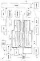
- FIG. 1 is a functional block diagram illustrating a configuration of a radiation tomography apparatus according to Embodiment 1.
- FIG. It is a figure explaining the structure of the detector ring which concerns on Example 1.
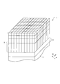
- FIG. 1 is a perspective view illustrating a configuration of a radiation detector according to Embodiment 1.
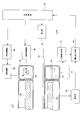
- FIG. It is sectional drawing explaining the structure of the top plate which concerns on Example 1.
- FIG. 3 is a cross-sectional view illustrating the configuration of a detector ring according to Embodiment 1.
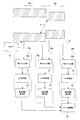
- FIG. FIG. 3 is a conceptual diagram illustrating in detail each unit related to coincidence counting according to the configuration of the first embodiment.
- 6 is a functional block diagram illustrating a configuration of a radiation tomography apparatus according to Embodiment 2.
- FIG. It is sectional drawing explaining the structure of the radiation tomography apparatus which concerns on 1 modification of this invention. It is a top view explaining the structure of the radiation tomography apparatus which concerns on a conventional structure.
- the best mode of the radiation tomography apparatus according to Embodiment 1 will be described.
- the ⁇ rays described below are an example of the radiation of Example 1.
- the present invention is applied to a PET apparatus, and in the second embodiment, the present invention is applied to a PET / CT apparatus.
- FIG. 1 is a functional block diagram illustrating the configuration of the radiation tomography apparatus according to the first embodiment.
- the radiation tomography apparatus 9 according to the first embodiment includes a top plate 10 that lies on the subject M and a gantry 11 having a through hole that surrounds the subject M.
- the top plate 10 is provided so as to pass through the opening of the gantry 11 and is movable back and forth along the direction in which the opening of the gantry 11 extends (z direction).
- Such movement of the top plate 10 is realized by the top plate moving mechanism 15.
- the top plate moving mechanism 15 is controlled by the top plate movement control unit 16.
- a detector ring 12 for detecting an annihilation gamma ray pair emitted from the subject M is provided inside the gantry 11, a detector ring 12 for detecting an annihilation gamma ray pair emitted from the subject M is provided.
- This detector ring 12 has a cylindrical shape extending in the body axis direction z of the subject M (corresponding to the extending direction of the central axis of the present invention), and the length thereof is 1.8 m or more. That is, the detector ring 12 extends to such an extent that the whole body of the subject M can be covered.
- the detector ring 12 according to the configuration of the first embodiment is configured such that the first detector ring 12a and the second detector ring 12b are arranged (connected) in the z direction while sharing the center axis of each other.
- the first detector ring 12a is formed by arranging around 100 radiation detectors 1 in an annular shape.
- the through hole 12d is viewed from the z direction, the through hole 12d is, for example, a regular 100-gon.
- FIG. 2B is a perspective view of the first detector ring 12a.
- the radiation detector 1 is connected in the z direction to form the first detector ring 12a.
- the second detector ring 12b is configured by arranging the radiation detectors 1 in an annular shape.
- the number of radiation detectors 1 constituting the second detector ring 12b is smaller than that of the first detector ring 12a.
- the first detector ring 12a has an inner diameter of about 650 mm in diameter.
- the inner diameter of the second detector ring 12b is about 300 mm in diameter.
- the gantry 11 is also divided into two parts. The two parts are a first gantry 11a covering the first detector ring 12a and a second gantry 11b covering the second detector ring 12b (see FIG. 1).
- FIG. 3 is a perspective view illustrating the configuration of the radiation detector according to the first embodiment.
- the radiation detector 1 includes a scintillator 2 that converts radiation into fluorescence, and a photodetector 3 that detects fluorescence.
- a light guide 4 for transmitting and receiving fluorescence is provided at a position where the scintillator 2 and the photodetector 3 are interposed.
- the structure of the radiation detector 1 is only an example of embodiment, and is not restricted to this aspect.
- the scintillator 2 is configured by scintillator crystals arranged three-dimensionally.
- the scintillator crystal is composed of Lu 2 (1-X) Y 2X SiO 5 (hereinafter referred to as LYSO ) in which Ce is diffused.
- the photodetector 3 can specify the fluorescence generation position indicating which scintillator crystal emits fluorescence, and can also specify the intensity of fluorescence and the time when the fluorescence is generated. it can.
- the top plate 10 has a characteristic shape. That is, as shown in FIG. 4A, the top plate 10 includes a first portion 10a that is wide in the radial direction of the first detector ring 12a and a second portion 10b that is narrow in the same direction in the z direction. Has been configured.
- the first portion 10a supports the head and body of the subject M
- the second portion 10b supports the leg of the subject M. Since the shoulder portion of the subject M is the widest, the first portion 10a that supports the shoulder portion of the subject M needs to be wide. However, since the second portion 10b does not have such a restriction, it can be made narrower than the first portion 10a.
- the radial direction of the first detector ring 12a is the direction in which the top 10 extends from the radiation detector of the first detector ring 12a toward the central axis (z axis) of the first detector ring 12a. For example, it refers to the body side direction of the subject M.
- the top plate moving mechanism 15 includes a pulley, a belt, a motor, and the like, and moves the top plate 10 forward and backward in the z direction according to the control of the top plate movement control unit 16.
- FIG. 4A shows a state in which the top plate 10 is housed inside the detector ring 12. At this time, the wide first portion 10a exists inside the large-diameter first detector ring 12a, and the narrow second portion exists inside the small-diameter second detector ring 12b. . In order to withdraw the subject M from the top board 10 from this state, the top board 10 is moved in the direction of the arrow in FIG. That is, when the top plate 10 is retracted from the inside of the detector ring 12, the top plate 10 is moved in the direction from the second detector ring 12b toward the first detector ring 12a.
- FIG. 4B shows a case where the top plate 10 retracted from the detector ring 12 is inserted inside the detector ring 12. Contrary to the above, the top plate 10 is moved in the direction from the first detector ring 12a toward the second detector ring 12b. Further, since the widths of the first portion 10a and the second portion 10b are different from each other, the side end of the first portion 10a that the second portion 10b is connected to is not coupled to the second portion 10b. It has an exposed portion 10c. The exposed portion 10c is provided with an approach sensor 10s, and its output is sent to the top board movement control unit 16. The proximity sensor corresponds to the sensing means of the present invention.
- the exposed portion 10c may interfere with the second detector ring 12b (more precisely, the second gantry 11b covering it).
- the output signal of the proximity sensor 10 s is sent to the top board movement control unit 16.
- the top plate movement control unit 16 controls the top plate 10 to be stationary when the exposed portion 10c approaches the second detector ring 12b to some extent. Therefore, the top plate 10 does not interfere with the detector ring 12.
- an infrared sensor can be used.
- the top plate 10 is provided with a restraining tool 10r that prohibits the movement of the subject M with respect to the top plate 10.
- a restraining tool 10r that prohibits the movement of the subject M with respect to the top plate 10.
- the radiation tomography apparatus 9 is further provided with various units for acquiring a tomographic image of the subject M as shown in FIG. Specifically, the radiation tomography apparatus 9 receives, from the detection data detected by the detector ring 12, a filter unit 20 that extracts valid data, and data that is regarded as valid by the filter unit 20.
- a fluorescence intensity calculation unit 22 that acquires the fluorescence intensity of the annihilation ⁇ -ray pair, a LOR specification unit 21 that specifies the incident position of the annihilation ⁇ -ray pair in the detector ring 12, a data storage unit 23 that stores detection data, A mapping unit 24 that forms a tomographic image of the subject M and a calibration unit 25 that applies calibration to the tomographic image of the subject M are provided.
- the calibration unit 25 refers to the calibration data stored in the calibration data storage unit 34 and removes the false image reflected in the tomographic image.
- the MRD storage unit 37 stores MRD described later.
- the input unit 38 is used to input a surgeon's operation, and for example, receives an MRD change.
- the radiation tomography apparatus 9 includes a main control unit 35 that performs overall control of each unit and a display unit 36 that displays a radiation tomographic image.
- the main control unit 35 is constituted by a CPU, and executes various programs, thereby allowing the top board movement control unit 16, the filter unit 20, the LOR specifying unit 21, the fluorescence intensity calculation unit 22, the mapping unit 24, and the calibration unit. 25 is realized.
- each above-mentioned part may be divided
- the filter unit 20 When the annihilation radiation pair enters the detector ring 12, two mutually independent detection data are output from the detector ring 12. The two detection data are paired and come from a single annihilation radiation pair. Detection data that cannot be paired is discarded. Such selection of detection data is performed by the filter unit 20. The filter unit 20 reads the clock data attached to the detection data, passes the pair of detection data detected at the same time to the LOR specifying unit 21 at the subsequent stage, and discards the detection data that cannot be paired.
- the filter unit 20 does not pass the detection data detected at the same time to the LOR specifying unit 21 unconditionally. That is, the filter unit 20 refers to an MRD (Maximum ring difference) stored in the MRD storage unit 37 and passes only detection data suitable for generation of a radiation tomographic image to the LOR specifying unit 21. . That is, as shown in FIG. 5, when annihilation ⁇ rays are incident on two scintillator crystals that are considerably separated in the z direction, the annihilation ⁇ rays are incident on the scintillator crystal along the z direction. As shown in FIG. 5, it is difficult to detect ⁇ rays incident at a sharp angle from the incident surface of the scintillator crystal, and the incident dose is reduced.
- MRD Maximum ring difference
- FIG. 6 is a conceptual diagram illustrating in detail each unit related to the coincidence counting according to the configuration of the first embodiment.
- the filter unit 20 shown in FIG. 1 includes a first filter unit 20a, a second filter unit 20b, and a third filter unit 20c.
- the first filter unit 20a is connected to the first detector ring 12a
- the second filter unit 20b is connected to the second detector ring 12b.
- the third filter unit 20c is connected to both the first detector ring 12a and the second detector ring 12b.
- the clock 19 is depicted as being connected only to the first detector ring 12a, but in reality it is also connected to the second detector ring 12b.
- the above-described connection relation is omitted for the purpose of simple drawing.
- the first filter unit 20a passes the detection data to the LOR specifying unit 21 when any of the annihilation gamma ray pairs is detected by the first detector ring 12a. That is, the first filter unit 20a, the LOR specifying unit 21, and the fluorescence intensity calculating unit 22 cooperate to count the number of simultaneous events that is the number of times that the annihilation ⁇ -ray is simultaneously detected by the first detector ring 12a.
- the coincidence counting unit 26a is configured.
- the second filter unit 20b passes the detection data to the LOR specifying unit 21 when any of the annihilation ⁇ -ray pairs is detected by the second detector ring 12b. That is, the second filter unit 20b, the LOR specifying unit 21, and the fluorescence intensity calculating unit 22 constitute a second coincidence unit 26b.
- the third filter unit 20c passes the detection data to the LOR specifying unit 21 when one of the annihilation radiation is detected by the first detector ring 12a and the other is detected by the second detector ring 12b. Specifically, as shown in FIG. 6, ⁇ rays are irradiated from the vanishing point P toward both detector rings 12a and 12b.
- the third filter unit 20c, the LOR specifying unit 21, and the fluorescence intensity calculating unit 22 cooperate to cause the two radiation detectors 1 belonging to the first detector ring 12a and the second detector ring 12b to emit radiation simultaneously. Count the number of simultaneous events that are detected. That is, the third filter unit 20c, the LOR specifying unit 21, and the fluorescence intensity calculating unit 22 constitute a third coincidence unit 26c.
- the configuration of the first embodiment includes the third coincidence unit 26c, it is possible to perform coincidence on the annihilation ⁇ -ray pairs detected across both the detector rings 12a and 12b. . Note that the determination of the simultaneity of the detected data takes into account the clock data associated with the detected data.
- the third coincidence unit corresponds to the inter-detector ring coincidence means of the present invention.
- the first filter unit 20a, the second filter unit 20b, and the third filter unit 20c select detection data in consideration of MRD. That is, the filter unit 20 sends detection data to the LOR specifying unit 21 only when the distance in the z direction between two scintillator crystals that simultaneously detect ⁇ rays is equal to or less than a predetermined distance indicated by the MRD.
- the distance indicated by the MRD described above is a value obtained by multiplying the width of the scintillator crystal in the z direction by an integer, and can be set independently from the arrangement pitch of the radiation detectors in the z direction. Note that an integer multiplied by the width of the scintillator crystal when calculating the predetermined distance is the MRD stored in the MRD storage unit 37.
- the radiation intensity is given to the detection data, and the LOR specifying unit 21 specifies a LOR (Line of Response) that is a line segment connecting two scintillator crystals. That is, it is a line segment that connects different scintillator crystals that are considered to have been incident with ⁇ rays simultaneously by emitting fluorescence during a period within a predetermined time window.
- the detection data output from the detector ring 12 includes position data indicating which scintillator crystal is used.
- the LOR specifying unit 21 obtains an LOR from two pieces of detection data considered to be due to an annihilation radiation pair.
- the detection data output from the LOR specifying unit 21 is stored in the data storage unit 23 via the fluorescence intensity calculation unit 22.
- the fluorescence intensity calculation unit 22 calculates the intensity of ⁇ rays related to the detection data.
- the data storage unit 23 stores how often an annihilation ⁇ -ray pair is detected for each LOR.
- the detection data stored in the data storage unit 23 is vector data in which LOR, fluorescence intensity, and detection time are related.
- the mapping unit 24 assembles vector data stored in the data storage unit 23 and generates a tomographic image of the subject M. The tomographic image generated in this way is displayed on the display unit 36, and the inspection is completed.
- At least two detector rings 12 for detecting ⁇ rays emitted from the subject M are provided.
- One of the detector rings 12 is a first detector ring 12a having an inner diameter sufficient to introduce the shoulder of the subject M, and the other is inner diameter than the first detector ring 12a.
- the width of the subject M is the widest at the shoulder, and it is not necessary to have a large inner diameter over the entire area of the detector ring 12. In the detector ring 12, the inner diameter of the region unrelated to the shoulder of the subject M can be reduced.
- the number of radiation detectors 1 constituting the detector ring 12 can be suppressed, so that an inexpensive radiation tomography apparatus 9 can be provided.
- the scintillator crystal mounted on the first detector ring 12a can be reduced to about 46% per unit width in the z direction as compared with the second detector ring 12b. Expected to go down.
- the diameter of the detector ring 12 can be reduced, both the spatial resolution and detection sensitivity of ⁇ rays are improved.
- the distance from the ⁇ -ray generation source to the radiation detector 1 increases, the dose of ⁇ -rays that reaches the radiation detector 1 decreases. Therefore, in order to improve the detection sensitivity, it is better that the distance between the subject M and the radiation detector 1 is short, and the inner diameter of the detector ring 12 is preferably small.
- the annihilation ⁇ -ray pair stores the positron that is the source of generation and the kinetic energy possessed by the electron. Accordingly, the traveling direction of each annihilation gamma ray pair is slightly shifted from the opposite direction by 180 degrees.
- the incident position of the detector ring 12 deviates from the ideal accordingly.
- the deviation width of the incident position in the detector ring 12 due to the deviation in the traveling direction of the annihilation ⁇ -ray pair increases, and the spatial resolution of the radiation tomography apparatus 9 deteriorates. That is, in order to provide the radiation tomography apparatus 9 with high spatial resolution, the inner diameter of the detector ring 12 should be small. According to the configuration of the first embodiment, both the above-described two effects can be achieved.
- the first coincidence unit 26a for simultaneously counting the annihilation ⁇ -ray pairs detected by the first detector ring 12a and the annihilation ⁇ -ray pair detected by the second detector ring 12b are simultaneously used.
- the second simultaneous counting unit 26b for counting the number of simultaneous events, which is the number of times the two radiation detectors 1 belonging to each of the first detector ring 12a and the second detector ring 12b simultaneously detect ⁇ rays, is determined.
- a third coincidence unit 26c for counting is provided.
- the first detector ring 12 and the second detector ring 12b are configured to recognize a single annihilation ⁇ -ray pair in cooperation, the number of data used for tomography is improved.
- the radiation tomography apparatus 9 that can generate a clear tomographic image can be provided.
- the subject M can be reliably introduced into the detector ring 12. That is, when the top plate 10 is inserted inside the two detector rings 12, the top plate 10 is moved in the direction from the first detector ring 12a to the second detector ring 12b. That is, the shoulder portion of the subject M is inserted from the side of the first detector ring 12a having a large inner diameter. Therefore, the shoulder of the subject M does not interfere with the second detector ring 12b regardless of the movement of the top board 10. The same applies to the case where the subject M is withdrawn from the detector ring 12.
- the top plate 10 when the top plate 10 is retracted from the inside of both detector rings 12a and 12b, the top plate 10 is moved in the direction from the second detector ring 12b to the first detector ring 12a. Therefore, the shoulder of the subject M does not interfere with the second detector ring 12b regardless of the movement of the top board 10.
- the inner diameter of the second detector ring 12b can be reliably reduced. That is, according to this configuration, the shape of the top plate 10 follows the shape inside the detector ring 12. That is, when the top plate 10 is inserted inside both detector rings 12, the wide first portion 10a is positioned inside the first detector ring 12a, and the narrow second portion 10b is the second portion. It is located inside the detector ring 12b. In addition, when the top plate 10 is retracted from the inside of both detector rings 12, the top plate 10 is moved in the direction from the second detector ring 12b toward the first detector ring 12a as shown in FIG. Since it moves, the wide first portion 10a does not pass through the second detector ring 12b and they do not interfere with each other.
- a safer radiation tomography apparatus 9 can be provided.
- An exposed portion 10c to which the second portion 10b is not coupled is provided at the side end of the first portion 10a on the second detector ring 12b side. This exposed portion 10c may interfere with the second detector ring 12b.
- the proximity sensor 10s that senses the approach of the exposed portion 10c to the second detector ring 12b is provided, and when the exposed portion 10c approaches the second detector ring 12b to some extent, the insertion of the top 10 is stopped. The Therefore, the top plate 10 and the second detector ring 12b do not interfere with each other, and a safe radiation tomography apparatus 9 can be provided.
- a safer radiation tomography apparatus 9 can be provided.
- the top plate 10 With the restraining tool 10r, when the top plate 10 is inserted into the detector ring 12, the hand portion of the subject M is fixed, so the top plate 10 and the second detector A hand part is not pinched by the ring 12b.
- the PET / CT apparatus has a configuration including the radiation tomography apparatus (PET apparatus) 9 described in the first embodiment and a CT apparatus that generates a tomographic image using X-rays.
- PET apparatus radiation tomography apparatus
- This is a medical device capable of generating a superimposed composite image.
- the configuration of the PET / CT apparatus according to the second embodiment will be described.
- the radiation tomography apparatus (PET apparatus) 9 described in the first embodiment can be used. Therefore, a CT apparatus which is a characteristic part in the second embodiment will be described.
- the CT apparatus 8 has a gantry 45.
- the gantry 45 is provided with an opening extending in the z direction, and the top plate 10 is inserted into the opening.
- the CT apparatus 8 is provided on the first detector ring 12a side of the radiation tomography apparatus 9, and is adjacent to the radiation tomography apparatus 9 from the z direction side.
- An gantry 45 supports an X-ray tube 43 that irradiates the subject with X-rays, an FPD (flat panel detector) 44 that has passed through the subject, and the X-ray tube 43 and the FPD 44.
- a support 47 is provided.
- the support 47 has a ring shape and is rotatable around the z axis.
- the rotation of the support 47 is performed by a rotation mechanism 39 including a power generation unit such as a motor and a power transmission unit such as a gear.
- the rotation control unit 40 controls the rotation mechanism 39.
- the X-ray tube corresponds to the radiation source of the present invention.
- the FPD corresponds to the radiation detection means of the present invention, and the support corresponds to the support means of the present invention.
- the rotation mechanism corresponds to the rotation means of the present invention, and the rotation control unit corresponds to the rotation control means of the present invention.
- the CT image generation unit 41 generates an X-ray tomographic image of the subject M based on the X-ray detection data output from the FPD 44.
- the superimposing unit 42 generates a superposition image by superimposing the PET image indicating the drug distribution in the subject output from the radiation tomography apparatus (PET apparatus) 9 and the above-described X-ray tomographic image. It has a configuration.
- the main control unit 35 executes various programs, and in addition to the mapping unit 24 and the calibration unit 25 according to the first embodiment, the rotation control unit 40, the CT image generation unit 41, the superposition unit 42, and the X-ray
- the pipe control unit 46 is realized.
- each above-mentioned part may be divided
- a method for obtaining a fluoroscopic image will be described.
- the X-ray tube 43 and the FPD 44 rotate around the z axis while maintaining their relative positions.
- the X-ray tube 43 intermittently irradiates the subject M with X-rays, and each time the CT image generation unit 41 generates an X-ray fluoroscopic image.
- the plurality of fluoroscopic images are assembled into a single tomographic image using the existing back projection method in the CT image generation unit 41, for example.
- a method for generating a composite image In order to acquire a composite image with the PET / CT apparatus, a region of interest of the subject M is introduced into the CT apparatus, and an X-ray tomographic image is acquired while changing the positions of the subject M and the gantry 54. In addition to this, a region of interest of the subject M is introduced into a radiation tomography apparatus (PET apparatus) 9 to acquire a PET image. Both images are superimposed by the overlapping unit 42, and the completed composite image is displayed on the display unit 36. Thereby, since the drug distribution and the internal structure of the subject can be recognized simultaneously, a tomographic image suitable for diagnosis can be provided.
- PET apparatus radiation tomography apparatus
- the radiation tomography apparatus 9 that can acquire both the internal structure of the subject M and the drug distribution can be provided.
- a PET device can generally obtain information relating to drug distribution.
- a composite image suitable for diagnosis can be generated by superimposing both images.
- the present invention is not limited to the above-described configuration, and can be modified as follows.
- the scintillator crystal referred to in each of the above embodiments is composed of LYSO.
- the scintillator crystal is composed of other materials such as GSO (Gd 2 SiO 5 ) instead. Also good. According to this modification, it is possible to provide a method of manufacturing a radiation detector that can provide a cheaper radiation detector.
- the fluorescence detector is composed of a photomultiplier tube, but the present invention is not limited to this. Instead of the photomultiplier tube, a photodiode, an avalanche photodiode, a semiconductor detector, or the like may be used.
- the top plate is movable.
- the present invention is not limited to this.
- the top plate may be fixed and the gantry 11 may be moved.
- the detector ring 12 has the first detector ring 12a and the second detector ring 12b, but the present invention is not limited to this. Three or more detector rings having different inner diameters may be provided.
- the subject M may be inserted from the head.
- the second detector ring 12b has an inner diameter sufficient to cover the head of the subject M and a length in the z direction. With such a configuration, the spatial resolution in the head is reliably improved.
- the top plate 10 also has a shape that follows the internal space of the detector ring 12.
- the present invention is suitable for a medical radiation tomography apparatus.
Landscapes
- Health & Medical Sciences (AREA)
- Life Sciences & Earth Sciences (AREA)
- Engineering & Computer Science (AREA)
- Medical Informatics (AREA)
- Physics & Mathematics (AREA)
- High Energy & Nuclear Physics (AREA)
- Molecular Biology (AREA)
- Optics & Photonics (AREA)
- General Health & Medical Sciences (AREA)
- Biomedical Technology (AREA)
- Nuclear Medicine, Radiotherapy & Molecular Imaging (AREA)
- Pathology (AREA)
- Public Health (AREA)
- Radiology & Medical Imaging (AREA)
- Veterinary Medicine (AREA)
- Heart & Thoracic Surgery (AREA)
- Surgery (AREA)
- Animal Behavior & Ethology (AREA)
- Biophysics (AREA)
- General Physics & Mathematics (AREA)
- Spectroscopy & Molecular Physics (AREA)
- Pulmonology (AREA)
- Theoretical Computer Science (AREA)
- Nuclear Medicine (AREA)
- Apparatus For Radiation Diagnosis (AREA)
Abstract
Description
すなわち、従来構成をそのまま全身検査用の放射線断層撮影装置に適応しようとすると、放射線断層撮影装置が高価なものとなってしまう。すなわち、検出器リング53をz方向に長いものとすると、搭載される放射線検出器の個数が増加し、検出器リング53の製造コストが大幅にアップする。近年において、被検体の全身を覆う程度に検出器リング53が幅広となっている放射線断層撮影装置が開発されつつある。放射線断層撮影装置のコストは、それに備えられる放射線検出器の個数に大きく左右されるので、検出器リング53の内径は小さいほうがよい。
すなわち、本発明に係る放射線断層撮影装置は、被検体から放射させる放射線を検出する放射線検出器が環状に配列されて構成される第1検出器リング、および第2検出器リングと、第1検出器リング、第2検出器リングの内側に設けられた天板とを備え、両検出器リングは、互いの中心軸を共有して中心軸方向に配列されているとともに、第1検出器リングの内径は、第2検出器リングの内径よりも大きくなっていることを特徴とするものである。
8 CT装置(画像生成装置)
9 放射線断層撮影装置
10 天板
10a 第1部分
10b 第2部分
10c 露出部分
10s 接近センサー(感知手段)
10r 拘束具(移動禁止手段)
12a 第1検出器リング
12b 第2検出器リング
26c 第3同時計数部(検出器リング間同時計数手段)
39 回転機構(回転手段)
43 X線管(放射線源)
44 FPD(放射線検出手段)
47 支持体(支持手段)
以下、実施例1に係る放射線断層撮影装置の各実施例を図面を参照しながら説明する。図1は、実施例1に係る放射線断層撮影装置の構成を説明する機能ブロック図である。実施例1に係る放射線断層撮影装置9は、図1に示すように、被検体Mを仰臥させる天板10と、被検体Mを包囲する貫通穴を有するガントリ11を有している。天板10は、ガントリ11の開口を貫通するように備えられているとともに、ガントリ11の開口の伸びる方向(z方向)に沿って進退自在となっている。この様な天板10の移動は、天板移動機構15によって実現される。天板移動機構15は、天板移動制御部16によって制御される。
次に、実施例1に係る放射線断層撮影装置の動作について説明する。まず、検出器リング12から退出された天板10に放射性薬剤が注射された被検体Mが載置される。天板10は、天板移動制御部16の制御にしたがって、検出器リング12の内部に導入される。このとき、被検体Mにおける撮影範囲の全てが検出器リング12の内部に位置することになる。被検体Mから照射される放射線の検出中、天板10は移動しない。このときの天板10と検出器リング12との位置関係は、図4(a)の如くとなっている。
Claims (7)
- 被検体から放射させる放射線を検出する放射線検出器が環状に配列されて構成される第1検出器リング、および第2検出器リングと、
前記第1検出器リング、前記第2検出器リングの内側に設けられた天板とを備え、
両検出器リングは、互いの中心軸を共有して前記中心軸方向に配列されているとともに、第1検出器リングの内径は、第2検出器リングの内径よりも大きくなっていることを特徴とする放射線断層撮影装置。 - 請求項1に記載の放射線断層撮影装置において、
前記第1検出器リング、前記第2検出器リングのそれぞれに属する2つの放射線検出器が同時に放射線を検出した回数である同時イベント数を計数する検出器リング間同時計数手段とを備えることを特徴とする放射線断層撮影装置。 - 請求項1または請求項2に記載の放射線断層撮影装置において、
前記天板を移動させる天板移動手段と、これを制御する天板移動制御手段とを備え、
前記天板は、前記天板移動手段に移動されることにより前記第1検出器リング、および前記第2検出器リングが連接する方向である連接方向に沿って移動可能であり、
前記天板を両検出器リングの内側に挿入させる場合、前記天板は、前記第1検出器リングから前記第2検出器リングに向かう方向に移動され、
前記天板を両検出器リングの内側から退避させる場合、前記天板は、前記第2検出器リングから前記第1検出器リングに向かう方向に移動されることを特徴とする放射線断層撮影装置。 - 請求項3に記載の放射線断層撮影装置において、
前記天板は、前記連接方向に連接された第1部分と、前記第1部分よりも前記第1検出器リングの径方向に幅狭の第2部分とを備え、
前記天板が両検出器リングの内側に挿入されたとき、前記第1部分は、前記第1検出器リングの内側に位置し、前記第2部分は、前記第2検出器リングの内側に位置することを特徴とする放射線断層撮影装置。 - 請求項4に記載の放射線断層撮影装置において、
前記第1部分の前記第2検出器リング側の側端には、前記第2部分が結合していない露出部分が設けられており、
前記露出部分の前記第2検出器リングに対する接近を感知する感知手段を備え、
前記天板制御手段は、前記感知手段の感知に基づいて、前記天板の前記第1検出器リングから前記第2検出器リングに向かう方向の移動を中止することを特徴とする放射線断層撮影装置。 - 請求項1ないし請求項5のいずれかに記載の放射線断層撮影装置において、
前記天板には、被検体の前記天板に対する移動を禁止する移動禁止手段が設けられていることを特徴とする放射線断層撮影装置。 - 請求項1ないし請求項6のいずれかに記載の放射線断層撮影装置において、
(A)前記天板に対し前記中心軸周りに回転可能な放射線源と、
(B)前記天板に対し前記中心軸周りに回転可能な放射線検出手段と、
(C)前記放射線源と前記放射線検出手段とを支持する支持手段と、
(D)前記支持手段を回転させる回転手段と、
(E)前記回転手段を制御する回転制御手段を備えた画像生成装置が
前記第1検出器リングに隣接して設けられることを特徴とする放射線断層撮影装置。
Priority Applications (4)
| Application Number | Priority Date | Filing Date | Title |
|---|---|---|---|
| US13/257,279 US20120001077A1 (en) | 2009-03-25 | 2009-03-25 | Radiation tomography apparatus |
| JP2011505655A JPWO2010109523A1 (ja) | 2009-03-25 | 2009-03-25 | 放射線断層撮影装置 |
| CN2009801583118A CN102362198A (zh) | 2009-03-25 | 2009-03-25 | 放射线断层摄影装置 |
| PCT/JP2009/001332 WO2010109523A1 (ja) | 2009-03-25 | 2009-03-25 | 放射線断層撮影装置 |
Applications Claiming Priority (1)
| Application Number | Priority Date | Filing Date | Title |
|---|---|---|---|
| PCT/JP2009/001332 WO2010109523A1 (ja) | 2009-03-25 | 2009-03-25 | 放射線断層撮影装置 |
Publications (1)
| Publication Number | Publication Date |
|---|---|
| WO2010109523A1 true WO2010109523A1 (ja) | 2010-09-30 |
Family
ID=42780238
Family Applications (1)
| Application Number | Title | Priority Date | Filing Date |
|---|---|---|---|
| PCT/JP2009/001332 Ceased WO2010109523A1 (ja) | 2009-03-25 | 2009-03-25 | 放射線断層撮影装置 |
Country Status (4)
| Country | Link |
|---|---|
| US (1) | US20120001077A1 (ja) |
| JP (1) | JPWO2010109523A1 (ja) |
| CN (1) | CN102362198A (ja) |
| WO (1) | WO2010109523A1 (ja) |
Cited By (1)
| Publication number | Priority date | Publication date | Assignee | Title |
|---|---|---|---|---|
| WO2014118823A1 (ja) * | 2013-01-31 | 2014-08-07 | 株式会社島津製作所 | 核医学診断装置 |
Families Citing this family (8)
| Publication number | Priority date | Publication date | Assignee | Title |
|---|---|---|---|---|
| US10987069B2 (en) | 2012-05-08 | 2021-04-27 | Spectrum Dynamics Medical Limited | Nuclear medicine tomography systems, detectors and methods |
| US9560970B2 (en) * | 2013-07-09 | 2017-02-07 | General Electric Company | Systems and methods for integration of a positron emission tomography (PET) detector with a computed-tomography (CT) gantry |
| JP6256608B2 (ja) * | 2014-07-04 | 2018-01-10 | 株式会社島津製作所 | 画像再構成処理方法 |
| CN106716177B (zh) * | 2014-11-18 | 2019-04-12 | 株式会社岛津制作所 | 断层图像显示装置 |
| WO2017214766A1 (zh) | 2016-06-12 | 2017-12-21 | 上海联影医疗科技有限公司 | 正电子发射断层成像系统及其图像重建方法 |
| CN106108929B (zh) * | 2016-06-17 | 2018-11-09 | 清华大学 | Spect成像装置 |
| WO2019000401A1 (en) | 2017-06-30 | 2019-01-03 | Shanghai United Imaging Healthcare Co., Ltd. | SYSTEM AND METHOD FOR PET IMAGING |
| CN112641455B (zh) * | 2019-10-09 | 2024-06-18 | 安徽麦德盈华影像技术有限公司 | 一种头部渐窄型全身pet装置 |
Citations (8)
| Publication number | Priority date | Publication date | Assignee | Title |
|---|---|---|---|---|
| JPH0617094Y2 (ja) * | 1988-09-30 | 1994-05-02 | 株式会社島津製作所 | ポジトロンect装置 |
| JP3038951B2 (ja) * | 1991-02-21 | 2000-05-08 | 株式会社島津製作所 | エミッションct装置 |
| JP2004533607A (ja) * | 2001-01-16 | 2004-11-04 | ボード・オブ・リージェンツ,ザ・ユニヴァーシティ・オヴ・テキサス・システム | 個々に回転可能な検出器モジュールおよび/または個々に移動可能なシールド部分を備えるpetカメラ |
| JP2005348841A (ja) * | 2004-06-09 | 2005-12-22 | Toshiba Corp | 画像診断装置 |
| JP2006513410A (ja) * | 2003-01-06 | 2006-04-20 | コーニンクレッカ フィリップス エレクトロニクス エヌ ヴィ | 一定半径でのシングルフォトン断層撮影法 |
| WO2007105536A1 (ja) * | 2006-03-10 | 2007-09-20 | Shimadzu Corporation | 核医学診断装置およびそれに用いられる診断システム |
| JP4013559B2 (ja) * | 2002-01-24 | 2007-11-28 | 株式会社島津製作所 | 医療用寝台マット |
| WO2008129666A1 (ja) * | 2007-04-17 | 2008-10-30 | National Institute Of Radiological Sciences | Pet装置、及び、その画像再構成方法 |
Family Cites Families (13)
| Publication number | Priority date | Publication date | Assignee | Title |
|---|---|---|---|---|
| JP3793266B2 (ja) * | 1995-10-20 | 2006-07-05 | 浜松ホトニクス株式会社 | ポジトロンct装置およびその画像再構成方法 |
| DE19947361A1 (de) * | 1999-10-01 | 2002-01-03 | Siemens Ag | Lagerungsvorrichtungssystem |
| US6772461B2 (en) * | 2000-05-24 | 2004-08-10 | David Gaspar | Portable trauma radiography/patient care system |
| JP4536212B2 (ja) * | 2000-05-24 | 2010-09-01 | 浜松ホトニクス株式会社 | Pet装置 |
| US6674083B2 (en) * | 2001-06-05 | 2004-01-06 | Hamamatsu Photonics K.K. | Positron emission tomography apparatus |
| US7063461B2 (en) * | 2002-11-21 | 2006-06-20 | Qfix Systems, Llc | Patient support device with shoulder depression device |
| US7379769B2 (en) * | 2003-09-30 | 2008-05-27 | Sunnybrook Health Sciences Center | Hybrid imaging method to monitor medical device delivery and patient support for use in the method |
| JP4857724B2 (ja) * | 2005-11-17 | 2012-01-18 | 株式会社日立製作所 | 核医学診断装置 |
| US20080056432A1 (en) * | 2006-08-30 | 2008-03-06 | General Electric Company | Reconstruction of CT projection data |
| US8546763B2 (en) * | 2008-01-22 | 2013-10-01 | Shimadzu Corporation | Positron computed tomography device |
| JP5619519B2 (ja) * | 2009-08-17 | 2014-11-05 | 株式会社東芝 | 医用頭部固定装置及び当該医用頭部固定装置を利用する医用寝台システム |
| US8084741B2 (en) * | 2009-10-01 | 2011-12-27 | Kabushiki Kaisha Toshiba | Configurable coincidence pairing and filtering system and method for positron emission tomography |
| KR101169708B1 (ko) * | 2010-04-26 | 2012-07-30 | 서강대학교산학협력단 | 큰 면적을 가진 마이크로셀로 구성된 gapd를 이용한 pet 검출기 모듈 |
-
2009
- 2009-03-25 CN CN2009801583118A patent/CN102362198A/zh active Pending
- 2009-03-25 US US13/257,279 patent/US20120001077A1/en not_active Abandoned
- 2009-03-25 JP JP2011505655A patent/JPWO2010109523A1/ja not_active Withdrawn
- 2009-03-25 WO PCT/JP2009/001332 patent/WO2010109523A1/ja not_active Ceased
Patent Citations (8)
| Publication number | Priority date | Publication date | Assignee | Title |
|---|---|---|---|---|
| JPH0617094Y2 (ja) * | 1988-09-30 | 1994-05-02 | 株式会社島津製作所 | ポジトロンect装置 |
| JP3038951B2 (ja) * | 1991-02-21 | 2000-05-08 | 株式会社島津製作所 | エミッションct装置 |
| JP2004533607A (ja) * | 2001-01-16 | 2004-11-04 | ボード・オブ・リージェンツ,ザ・ユニヴァーシティ・オヴ・テキサス・システム | 個々に回転可能な検出器モジュールおよび/または個々に移動可能なシールド部分を備えるpetカメラ |
| JP4013559B2 (ja) * | 2002-01-24 | 2007-11-28 | 株式会社島津製作所 | 医療用寝台マット |
| JP2006513410A (ja) * | 2003-01-06 | 2006-04-20 | コーニンクレッカ フィリップス エレクトロニクス エヌ ヴィ | 一定半径でのシングルフォトン断層撮影法 |
| JP2005348841A (ja) * | 2004-06-09 | 2005-12-22 | Toshiba Corp | 画像診断装置 |
| WO2007105536A1 (ja) * | 2006-03-10 | 2007-09-20 | Shimadzu Corporation | 核医学診断装置およびそれに用いられる診断システム |
| WO2008129666A1 (ja) * | 2007-04-17 | 2008-10-30 | National Institute Of Radiological Sciences | Pet装置、及び、その画像再構成方法 |
Cited By (1)
| Publication number | Priority date | Publication date | Assignee | Title |
|---|---|---|---|---|
| WO2014118823A1 (ja) * | 2013-01-31 | 2014-08-07 | 株式会社島津製作所 | 核医学診断装置 |
Also Published As
| Publication number | Publication date |
|---|---|
| CN102362198A (zh) | 2012-02-22 |
| US20120001077A1 (en) | 2012-01-05 |
| JPWO2010109523A1 (ja) | 2012-09-20 |
Similar Documents
| Publication | Publication Date | Title |
|---|---|---|
| WO2010109523A1 (ja) | 放射線断層撮影装置 | |
| US8351566B2 (en) | PET device | |
| JP5610248B2 (ja) | 放射線断層撮影装置 | |
| US20040227091A1 (en) | Methods and apparatus for radiation detecting and imaging using monolithic detectors | |
| JP7578450B2 (ja) | 核医学診断装置 | |
| US8395128B2 (en) | Radiation tomography apparatus | |
| JP6058272B2 (ja) | 核医学診断装置及び制御方法 | |
| JP5360418B2 (ja) | 放射線断層撮影装置 | |
| CN103619246A (zh) | 医用图像诊断装置 | |
| JP5541005B2 (ja) | 放射線断層撮影装置 | |
| JP2011185716A (ja) | 放射線断層撮影装置 | |
| JP3851575B2 (ja) | Pet検査装置 | |
| US8519341B2 (en) | Radiation tomography apparatus | |
| US9348033B2 (en) | Positron CT apparatus | |
| JP3904220B1 (ja) | 陽電子放出型断層撮影装置およびそのトランスミッション撮像の制御方法 | |
| JP6516019B2 (ja) | 放射線断層撮影装置 | |
| JP5794196B2 (ja) | 乳房検診用放射線断層撮影装置 | |
| JP5218270B2 (ja) | 乳房検診用放射線断層撮影装置 | |
| JP2024055098A (ja) | Pet装置、方法及びプログラム | |
| JP5725190B2 (ja) | 放射線断層撮影装置 | |
| JP2010164485A (ja) | ガンマカメラ | |
| JP2005249412A (ja) | 放射能画像化装置 | |
| JP2010266234A (ja) | 放射線断層撮影装置 | |
| JP2010190711A (ja) | 放射線断層撮影装置 |
Legal Events
| Date | Code | Title | Description |
|---|---|---|---|
| WWE | Wipo information: entry into national phase |
Ref document number: 200980158311.8 Country of ref document: CN |
|
| 121 | Ep: the epo has been informed by wipo that ep was designated in this application |
Ref document number: 09842141 Country of ref document: EP Kind code of ref document: A1 |
|
| ENP | Entry into the national phase |
Ref document number: 2011505655 Country of ref document: JP Kind code of ref document: A |
|
| WWE | Wipo information: entry into national phase |
Ref document number: 13257279 Country of ref document: US |
|
| NENP | Non-entry into the national phase |
Ref country code: DE |
|
| 122 | Ep: pct application non-entry in european phase |
Ref document number: 09842141 Country of ref document: EP Kind code of ref document: A1 |