WO2010107117A1 - 通信装置および通信方法 - Google Patents
通信装置および通信方法 Download PDFInfo
- Publication number
- WO2010107117A1 WO2010107117A1 PCT/JP2010/054853 JP2010054853W WO2010107117A1 WO 2010107117 A1 WO2010107117 A1 WO 2010107117A1 JP 2010054853 W JP2010054853 W JP 2010054853W WO 2010107117 A1 WO2010107117 A1 WO 2010107117A1
- Authority
- WO
- WIPO (PCT)
- Prior art keywords
- information
- communication
- power supply
- state
- abnormality information
- Prior art date
- Legal status (The legal status is an assumption and is not a legal conclusion. Google has not performed a legal analysis and makes no representation as to the accuracy of the status listed.)
- Ceased
Links
Images





Classifications
-
- H—ELECTRICITY
- H04—ELECTRIC COMMUNICATION TECHNIQUE
- H04L—TRANSMISSION OF DIGITAL INFORMATION, e.g. TELEGRAPHIC COMMUNICATION
- H04L12/00—Data switching networks
- H04L12/02—Details
- H04L12/10—Current supply arrangements
-
- H—ELECTRICITY
- H04—ELECTRIC COMMUNICATION TECHNIQUE
- H04L—TRANSMISSION OF DIGITAL INFORMATION, e.g. TELEGRAPHIC COMMUNICATION
- H04L12/00—Data switching networks
- H04L12/28—Data switching networks characterised by path configuration, e.g. LAN [Local Area Networks] or WAN [Wide Area Networks]
- H04L12/2803—Home automation networks
- H04L12/2807—Exchanging configuration information on appliance services in a home automation network
-
- H—ELECTRICITY
- H04—ELECTRIC COMMUNICATION TECHNIQUE
- H04L—TRANSMISSION OF DIGITAL INFORMATION, e.g. TELEGRAPHIC COMMUNICATION
- H04L12/00—Data switching networks
- H04L12/28—Data switching networks characterised by path configuration, e.g. LAN [Local Area Networks] or WAN [Wide Area Networks]
- H04L12/2803—Home automation networks
- H04L12/2823—Reporting information sensed by appliance or service execution status of appliance services in a home automation network
- H04L12/2827—Reporting to a device within the home network; wherein the reception of the information reported automatically triggers the execution of a home appliance functionality
Definitions
- the present invention relates to a communication device and a communication method.
- the abnormality information includes information on a failure inside the device, error information due to a user's erroneous operation, recall information from a device manufacturing vendor, and the like.
- the anomaly information should include log information for transmitting the operation history of the device to a server on the Internet, and analysis information for presenting the analysis result of the log information to the user, in order to diagnose the failure of the device. I assume.
- Patent Document 1 proposes a system for automatically starting up a television without user intervention and displaying emergency information at the time of gas abnormality or the like. Moreover, in patent document 2, the system which registers automatically the information regarding a failure on the server on the internet is proposed, without the user of an electric equipment doing operation
- the abnormality information to be notified and the power state regarding power saving of each device are not properly considered.
- DTV Digital Television
- Patent Document 3 proposes a trigger signal generating device that receives a wireless signal and generates a trigger signal to shift the state of the device, and in a state where the main power supply of the device is disconnected, The feature is that almost no standby power is generated.
- the trigger signal generator itself can not perform communication processing with other devices.
- the related art has a problem in that the abnormality information to be notified and the power state regarding power saving of each device are not properly considered.
- the means for transmitting information after lowering the standby power of the device to the limit is not considered, and the power consumption is reduced. There was a problem with poor efficiency.
- the present invention has been made to solve the above problems, and determines the method of transmitting the abnormal information based on the power state of the other device that notifies the abnormal information and the notification priority of the abnormal information, and determines the abnormal information.
- An object of the present invention is to provide a communication device and a communication method that can realize reliable information transmission even when the power of the device to be transmitted is cut off.
- an information generation unit that detects an abnormal state of a device and generates abnormal information, and a power state storage unit that stores a power state of the device that is a notification counterpart of the abnormal information.
- An information type storage unit that stores the abnormality information for each type; a determination unit that determines a transmission method of the abnormality information from the power state and the type of the abnormality information; And a communication processing unit that transmits information.
- the method of transmitting the failure information is determined based on the power state of the other device which notifies the failure information and the notification priority of the failure information. Communication is possible.
- FIG. 7 is a table diagram showing determination conditions of the write instruction determination unit of the transmission side communication device.
- FIG. 7 is a diagram showing an operation when a notification destination device of abnormality information is in a main power supply activation state.
- movement in case the notification other party apparatus of abnormality information is only the communication adapter working, and is the abnormality information which requires emergency for notification.
- movement in case the notification other party apparatus of abnormality information is only the communication adapter working, and is the abnormality information which does not require urgently for notification.
- FIG. 7 is an operation flowchart of the transmission side and reception side communication devices.
- FIG. 1 shows a configuration of a communication system related to transmission of abnormality information in the present embodiment.
- Each of the DTV and the white goods has a communication interface, and can transmit and receive messages with other devices.
- ECHONET (TM) exists as a communication standard regarding white goods such as a refrigerator, a washing machine, and an air conditioner.
- remote control such as lighting and air conditioning, monitoring, cooperative operation, etc. becomes possible via a network.
- DLNA Digital Living Network Alliance
- TM Digital Living Network Alliance
- Gateway equipment is required.
- the user can control white goods 102 such as a lighting device and an air conditioner in the house through the display screen of the DTV 101.
- the UPnP (TM) message transmitted from the DTV 101 is temporarily received by the HGW 103, analyzed for protocol information, and converted to an ECHONET (TM) message, and then notified to the corresponding white goods 102. Perform the process.
- TM UPnP
- a system is assumed in which information on the occurrence of an abnormality of devices is transmitted between devices or between devices and a server on the Internet, and a solution to the abnormality is presented to the user. Therefore, the configuration of the communication system shown in FIG. 1 (a) will be described in more detail.
- a white goods home appliance for example, a washing machine
- the HGW 103 is notified of abnormality information.
- the HGW 103 notifies the application service provider (ASP) server 104 on the Internet using either of the following methods: accumulating abnormality information and transmitting abnormality information immediately or transmitting abnormality information immediately when an event occurs .
- ASP application service provider
- the ASP server 104 analyzes the type of abnormality included in the abnormality information transmitted from the HGW 103, and performs analysis processing as to whether an abnormality has occurred due to a component failure of the device or an abnormality has occurred due to a user's erroneous operation.
- the analysis information to be the analysis result of the server is transmitted from the ASP server 104 to the HGW 103 by any of the means of the HGW 103 inquiring at regular intervals or notification from the ASP server 104 to the HGW 103 side.
- the HGW 103 causes the DTV 101 to display detailed analysis result information, for example, and presents a solution to the abnormality to the user.
- a URL Uniform Resource Locator
- the HGW 103 directly reports the information to the corresponding device, and notifies the user that the device has a problem through blinking of an LED lamp of the device, ringing of a buzzer, or the like.
- an application in which the operation log information of the device is analyzed on the side of the ASP server 104 and used for diagnosing a sign of failure may be considered. Also in this case, transmission of analysis information from the ASP server to the HGW and notification to a display device such as a DTV can be implemented similarly.
- the device on the transmission side of the abnormality information transmits the abnormality information based on the power state of the other device to which the information is notified and the notification priority of the abnormality information. Determining the method enables reliable information transmission even when the power of the other device is cut off. Details regarding the present embodiment will be described using an apparatus configuration, a communication sequence, and an operation flowchart.
- FIG. 1 (b) is a block diagram showing a transmitting communication device 110 according to the present embodiment.
- the transmission-side communication device 110 includes an information generation unit 111, an information type storage unit 112, a power state storage unit 113, a determination unit 114, a protocol processing unit 115, a write instruction unit 117, a start instruction unit 116, a communication unit 118, a first unit.
- the communication processing unit 118a and the second communication processing unit 118b are provided.
- the information generation unit 11 detects an error due to a component failure inside the device or an erroneous operation by the user, and generates abnormality information. Also, the operation status of the device is periodically acquired to generate log information.
- the transmitting communication device 110 is an ASP server
- analysis processing is performed based on the received abnormality information, and a solution method for the abnormality is generated as analysis information, and information on equipment recall and power activation of the equipment. It also generates information etc. for control.
- the transmitting-side communication device 110 is the HGW
- the abnormality information including the failure or error of the HGW itself
- the information type storage unit 112 stores the abnormality information generated by the information generation unit 111 for each type.
- the abnormality information is classified into three types of information that requires an emergency for notification (information A), information that does not require an emergency for notification (information B), and information for inhibiting power activation (information C).
- the information A is, for example, a recall notification from the ASP server, abnormality information at the time of abnormality occurrence of the home appliance, and the like.
- analysis information generated based on abnormality information and generated analysis information is also preferably classified as information A, in the case where a response should be made immediately as in the case of failure repair.
- Information B if there is no problem even if the corresponding timing is forward after a certain time, such as log information of each device regularly collected by the device and notified to the ASP server via the HGW, as information B It is desirable to classify.
- Information C is used to forcibly stop the use of the corresponding home electric appliance if a recall occurs which requires a thorough response, which may lead to a serious accident.
- the correspondence between the abnormality information and the type does not have to be limited to the above-described one, and can also be applied to a method in which the transmission side communication device 110 of the abnormality information judges according to the situation.
- the power supply state storage unit 113 stores the power supply state of the other device to which the abnormality information is to be notified.
- the power state is classified into three types of states: main power activation, activation of communication adapter only, and standby power 0 state.
- main power activation in addition to communication protocol processing by UPnP (TM) or ECHONET (TM), analysis processing by the information generation unit 111 can also be executed.
- TM communication protocol processing
- TM ECHONET
- analysis processing by the information generation unit 111 can also be executed.
- only the communication adapter for example, only wired communication processing by IEEE 802.3 and wireless communication processing by IEEE 802.11 can basically be implemented, and the main functions of devices including the OS (Operating System) are in sleep state It is impossible to execute complicated protocol processing and application processing.
- the protocol processing in the present invention means message communication processing by UPnP (TM) or ECHONET (TM). Even when only the communication adapter is activated, it is possible to transmit and receive information itself. However, it is assumed that the receiving device in a state where only the communication adapter is activated can not analyze complicated message information such as an XML (extensible Markup Language) document in UPnP (TM). In the standby power 0 state, as in the system disclosed in Patent Document 3, only a trigger device that receives a specific signal and generates a trigger signal for shifting the state of the device is operating; Although it is almost impossible to neglect the transmission procedure by the wired communication processing by IEEE 802.3 or the wireless communication processing by IEEE 802.11 as described above. The main power is also in the state of being disconnected.
- the method of acquiring the power state of another device can be realized by adding the power state to the end message of the device.
- information on the power supply state of the main unit can be acquired from the communication adapter unit by using a message related to the operation state acquisition.
- HTTP Hyper Text Transfer Protocol
- the determination unit 114 determines the method of transmitting the abnormality information from the information of the information type storage unit 112 and the power state storage unit 113.
- FIG. 2 shows a determination table used by the determination unit 114 of the transmission side communication device 110.
- the transmission method of information is uniquely determined from the information of the power supply state storage unit and the information of the information type storage unit. Each transmission method in FIG. 2 will be described later with reference to FIGS. 3 to 6.
- the protocol processing unit 115 transmits abnormality information by generating and transmitting a protocol message by UPnP (TM) or ECHONET (TM).
- the writing instructing unit 117 generates a message instructing recording of the abnormality information to the non-volatile storage unit when the main power of the notification other device of the abnormality information is cut off and only the communication adapter is activated.
- Send The message instructing recording in the non-volatile storage unit is composed of a fixed information element, and analysis of complicated contents is unnecessary, so the intervention of the protocol processing unit is unnecessary.
- the external device only records the abnormality information received via the communication adapter without activating the main power of the device, and when the main power is activated by the user's operation or when the main power is activated every certain period, Perform acquisition and protocol processing or application processing.
- the start instructing unit 116 generates and transmits a specific signal, and performs control to shift the state of the other device. That is, in the other device, a first communication processing unit that receives a specific signal and generates a trigger signal, and a second communication processing unit that performs wired communication processing by IEEE 802.3 and transmission control by wireless communication processing by IEEE 802.11.
- the transmitting side communication device 110 activates the second communication processing unit of the other device when the other device is in the standby power 0 state (both the main power supply and the second communication processing unit are in the sleep state).
- the signal of (1) is generated and transmitted toward the first communication processing unit of the other device.
- the first communication processing unit and the second communication processing unit do not necessarily have to be physically separated elements, and the operation state in one communication processing unit can be “transmission / reception enabled state” “only the trigger signal can be received” Then, a method of configuring the communication unit may be considered.
- the first communication processing unit 118 a of the transmission side communication device 110 communicates with the first communication processing unit of the other device. That is, when a specific signal is received, a specific signal is generated and transmitted to the communication processing unit that generates a trigger to change the state of the device.
- the first communication processing unit 118 a may perform wireless signal transmission or wired signal transmission.
- the second communication processing unit 118 b performs wired communication processing according to IEEE 802.3 and wireless communication processing according to IEEE 802.11. That is, the message transmission / reception of the abnormality information is performed via the second communication processing unit 118 b.
- IEEE 802.3 IEEE 802.11
- other communication means such as FDDI (Fiber Distributed Data Interface) may be used.
- the first communication processing unit 118 a and the second communication processing unit 118 b are controlled by the communication unit 118. Specifically, the first communication processing unit 118a is selected and transmitted when transmitting the abnormality information or the abnormality information write instruction request, and the second communication processing unit 118b is selected when transmitting the activation instruction message of the other device. And send.
- FIG. 1C is a block diagram showing the receiving communication device 120 according to the present embodiment.
- the reception-side communication device 120 includes an information processing unit 121, a protocol processing unit 122, a non-volatile storage unit 123, a writing control unit 124, a main power control unit 125, a communication unit 126, a first communication processing unit 126a, and a second communication process. It consists of the part 126b.
- the information processing unit 121 receives the recall notification, the abnormality information, the analysis information, the periodic log, and the information for prohibiting the power source activation received from the transmission side communication device 120, the information processing unit 121 performs processing corresponding to the respective information. That is, when abnormality information is received, analysis processing is performed.
- the analysis information is received, for example, if the DTV is the receiving communication device 120, processing of displaying the analysis result on the screen is performed. If the regular log is received, the log information is analyzed to diagnose a failure sign or the like. When the information for inhibiting the power supply start is received, the main power supply cut-off process is started.
- the protocol processing unit 122 performs generation, analysis, and transmission / reception processing of a protocol message by UPnP (TM), ECHONET (TM), or the like, as with the transmission side communication device 120.
- the non-volatile storage unit is realized by, for example, a NAND flash memory or the like.
- the write control unit 124 performs recording of the protocol message including the abnormality information on the non-volatile storage unit 123 according to an instruction of the transmission side communication device 120. Since the write control unit does not perform complicated protocol processing, the content is not analyzed, and only processing for recording the received message is performed.
- the main power control unit 125 When the main power control unit 125 receives information including a specific pattern, the main power control unit 125 performs processing of activating the main power of the device, and is realized, for example, by magic packet reception processing by WoL (Wake on LAN). In the present embodiment, the processing by the write control unit 124 and the main power control unit 125 can be handled as processing inside the communication adapter, and can be performed when the power of the communication adapter is activated.
- the communication unit 126 includes a first communication processing unit 126a and a second communication processing unit 126b.
- the first communication processing unit 126a operates as the communication unit 126 that generates a trigger signal that changes the state of the device when a specific signal is received.
- the power supply of the second communication processing unit 126b operating as the communication adapter 120a is activated, and control such as activation of the main power supply of the device body is performed.
- the first communication processing unit 126a may use any means of wireless signal reception and wired signal reception.
- the second communication processing unit 126b performs wired communication processing according to IEEE 802.3 and wireless communication processing according to IEEE 802.11, and performs transmission / reception processing of a protocol message including abnormality information.
- the implementation mode is not limited to IEEE 802.3 or IEEE 802.11, and other communication methods such as FDDI may be used.
- the standby power 0 state indicates a state in which only the first communication processing unit 126a is operating.
- the state in which only the communication adapter is activated means that the communication unit 126 including the first communication processing unit 126a and the second communication processing unit 126b, the write control unit 124, the non-volatile storage unit 123, and the main power control unit 125 operate. Show the status.
- the main power supply activation state is operating including main functions such as an information processing unit and a protocol processing unit, and is a state in which analysis processing can be performed on received abnormality information.
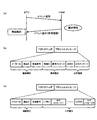
- FIG. 3 (a) shows a scene in which abnormality information is transmitted from the HGW to the DTV.
- the white goods shown in FIG. 1 when an error due to the user's erroneous operation or a failure occurs in the device parts, the white goods transmit information to the ASP server or DTV via the HGW.
- the abnormality information in FIG. 1 when an error due to the user's erroneous operation or a failure occurs in the device parts, the white goods transmit information to the ASP server or DTV via the HGW.
- 3A is to be handled in a broad sense including information on an abnormal condition generated in the device (error or component failure), recall notification from an ASP server, analysis information, etc. Do.
- an abnormal condition generated in the device error or component failure
- recall notification from an ASP server analysis information, etc.
- the DTV transmits an event registration message for transmitting event information when an event occurs to the HGW.
- the HGW After the event registration message is received by the HGW, when abnormality information (error or failure abnormality information, analysis information, recall notification, etc.) occurs, transmission processing of the abnormality information is performed.
- the information is usually transmitted to a plurality of devices waiting to receive the same type of event information by an IP (Internet Protocol) multicast transmission method.
- IP Internet Protocol
- the HGW transmits a control request message to the DTV by IP unicast, and transmits information to each individual device.
- the DTV analyzes the information and performs display processing on the screen as necessary.
- the HGW transmits the abnormality information to the DTV, but in the reverse direction, the DTV transmits the abnormality information to the HGW (in this case, mainly the error information of the error or the failure). The same procedure can be used also in the situation of transmitting the corresponding.
- the HGW When the HGW receives the abnormality information, it carries out information transmission to the ASP server. Furthermore, although it is not transmission of abnormality information, it is possible to apply the same procedure also when notifying control instructions (starting of an air conditioner or lighting of lighting) to a white goods from the DTV.
- FIGS. 3B and 3C show the configuration of a communication message including abnormality information in the present embodiment.
- FIG. 3 (b) is a message including abnormality information and analysis information for the abnormality due to an error or part failure
- FIG. 3 (c) is a message including log information periodically acquired by the device.
- the communication message is composed of a TCP / IP (Transmission Control Protocol / Internet Protocol) header portion and a protocol message portion.
- TCP / IP Transmission Control Protocol / Internet Protocol
- the protocol message of FIG. 3B is realized by a structured document according to an XML (extensible Markup Language) document.
- the protocol message (XML document) indicating abnormality information in the present embodiment includes information such as a maker ID (IDentifier), a product ID, a manufacturing number, an abnormality ID, an abnormality message, an analysis ID, and an analysis message.
- the maker ID, the product ID, and the serial number indicate the device type.
- the maker ID is information for uniquely identifying the manufacturer of the device.
- the product ID is information for identifying the product form of a device such as a DTV, an air conditioner, or an HGW.
- the serial number is a serial number assigned to the product to be shipped, and a unique number is assigned to each product, and is used when the manufacturer manages the owner or prevents the product from being disguised. It is also used for reference when problems such as recalls occur.
- An anomaly ID and an anomaly message indicate an anomaly type.
- the anomaly ID is used to identify an error code defined for each manufacturer.
- the error message is composed of character information such as information on component failure of the device.
- the analysis ID and the analysis message indicate the analysis type.
- the analysis ID is an identification code that defines the diagnosis result for an abnormality for each manufacturer. For example, in the case of abnormality information related to the occurrence of a device failure, analysis result information such as whether the device can be used continuously or whether it is necessary to contact a support center corresponds.
- the analysis message is composed of information on the analysis ID as text information, and includes, for example, analysis information to be displayed on the DTV, URL (Uniform Resource Locator) information to a Web server for browsing more detailed information, etc.
- URL Uniform Resource Locator
- the analysis message is composed of information on the analysis ID as text information, and includes, for example, analysis information to be displayed on the DTV, URL (Uniform Resource Locator) information to a Web server for browsing more detailed information, etc.
- URL Uniform Resource Locator
- the analysis message is composed of information on the analysis ID as text information, and includes, for example, analysis information to be displayed on the DTV, URL (Uniform Resource Locator) information to a Web server for browsing more detailed information, etc.
- TM Uniform Resource Locator
- FIG. 3C shows a communication message including log information periodically acquired by the device, which includes a log ID for identifying a log level defined for each manufacturer, and character information of the log message. Ru. Taking into consideration that the device accumulates a plurality of log
- FIG. 1 corresponds to the case where the power supply state of the other device in FIG. It is desirable to notify the user of abnormality information having a high degree of urgency, such as a recall or a component failure of the device, immediately.
- a recall or a component failure of the device
- main power supply it is possible to execute main processing such as application processing and protocol processing, but on the other hand, more power consumption is required.
- WoL is a technology for remotely controlling power control (main power on / off) of a computer connected to a computer network.
- the communication adapter is supplied with the minimum necessary power, and when a communication message including a specific pattern is received, the main power supply activation process and the disconnection process are performed.
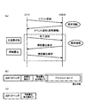
- FIG. 4A shows an operation sequence in the case where the main power supply of the notification other device of the abnormality information is cut off and the notification requires urgency.
- the event message is transmitted from the HGW while the main power supply of the DTV which is the notification counterpart device is activated. After that, when the main power of the DTV is turned off by the operation of the user, the end notification is transmitted before the end of the cutting process.
- TM UPnP
- the HGW that has received the end notification message from the DTV updates the information in the power supply state storage unit, and stores the state of the DTV as the operating state of only the communication adapter.
- the end notification message may be realized on an IP multicast basis, but a method of notifying information by IP unicast for each device may be used as a control message.
- FIG. 4A when abnormality information is generated on the HGW after the main power of the DTV is cut off, the determination unit 114 performs a determination process based on the information of the information type storage unit 112 and the power state storage unit 113, The HGW generates and sends a message for instructing the DTV communication adapter to activate the main power supply.
- FIG. 4B shows the configuration of the WoL magic packet as an example of a communication message for activating the main power supply of the other device.
- the WoL magic packet includes a UDP / IP (User Datagram Protocol / Internet Protocol) header, a synchronization identifier, and a boot device MAC address.
- UDP / IP User Datagram Protocol / Internet Protocol
- the communication adapter 120a of the receiving-side communication device 120 in the main power-off state performs communication message reception processing, and determines whether a synchronization identifier including a specific sequence for WoL control included in the message exists or not. To analyze. If the synchronization identifier does not exist, the process related to power control is not performed. When the synchronization identifier is recognized, the MAC address of the communication adapter to be controlled is successively added for a specific number of times following the identifier. Even when the MAC address of the communication adapter and the activation device MAC address do not match, the process related to power control is not performed.
- the MAC address of the communication adapter indicates the MAC address of the second communication processing unit 126b.
- the main power supply start process is started.
- the DTV activated by the main power supply performs event registration processing for receiving an event notification message to the HGW.
- the event notification message is immediately transmitted.
- the DTV having received the abnormality information performs the information analysis process and displays it on the screen, as in the embodiment in FIG. 3A.
- notification of abnormality information may use an IP multicast-based transfer method when an event occurs, or may use a control message to transfer to individual devices on an IP unicast basis.
- the termination notification message transmitted before the DTV disconnects the main power is discarded due to an error on the transmission path, the power supply that the transmitting communication device recognizes when the power of the DTV is unexpectedly disconnected due to a power failure or the like. If the protocol message transmission fails because the state and the actual power state are not consistent, the power state of the other device is considered to be the standby power 0 state where only the power saving adapter is operating, and the subsequent state It is desirable to carry out the treatment.
- FIG. 5 shows the configuration of an operation sequence and a communication message in the case where information not requiring urgent notification is transmitted in a state where the main power supply of the notification other device of the abnormal information is asleep and only the communication adapter is in operation. ing. It is considered that log information regarding the operation state of the device, analysis information of an error due to a user's erroneous operation, and the like do not need to be notified until the main power of the device of the notification destination is activated. Here, there is a problem that when the main power of the other device is activated as in the recall of white goods, there is a dangerous situation.
- the determination unit 114 of the transmission-side communication device 110 in the present embodiment determines that the other device is in the state where only the communication adapter is activated and the type of the abnormal information is the information B or the information C. Without activating the main power supply of the device, a message instructing writing of information to the non-volatile storage unit 123 in the receiving communication device 120 is generated and transmitted.
- FIG. 5A shows an operation sequence in the case of instructing to write information in the non-volatile storage unit 123 without activating the main power supply of the other device.
- the transmitting communication device 110 recognizes that the power state of the other device has transitioned with the reception of the end notification message, and stores the power state memory. Update the information of part 113.
- the power supply state storage unit 113 stores an identifier of a device such as a MAC address and power supply state information in a corresponding manner. After that, when abnormal information such as log information that does not require an emergency for notification or information that prohibits main power activation of the other device occurs (or is received from another device), an information write request message is generated Send.
- FIG. 1 shows an operation sequence in the case of instructing to write information in the non-volatile storage unit 123 without activating the main power supply of the other device.
- the information write request message includes a UDP / IP header, a synchronization identifier, an information write request identifier, and a protocol message.
- the UDP / IP header and the synchronization identifier are handled in the same manner as the WoL magic packet in FIG. 4 (b).
- the synchronization identifier is recognized in the reception side communication device 120 in which the main power supply is asleep and only the communication adapter is in operation, whether or not the device is the device to be written is the information write request identifier The determination is made based on the information, and when the corresponding device is recognized, the subsequent protocol message is recorded in the non-volatile storage unit 123.
- the information writing identifier is a target device for recording information in the same way as the method of adding the starting device MAC address for a specific number of times in order to identify the target device of main power activation in the WoL magic packet of FIG. It may be realized by a method of making MAC addresses continuous in order to identify.
- the communication adapter 120 a After recognizing the information write request identifier, the communication adapter 120 a performs control to write a protocol message following the information in the non-volatile storage unit 123. By designating a MAC broadcast address as the information write identifier, it is possible to record information on all the receiving communication devices on the same network.
- the non-volatile storage unit 123, the write control unit 124 and the like in the communication adapter of the reception side communication device 120 shown in FIG. Need to be However, the non-volatile storage unit 123 and the write control unit 124 do not necessarily have to be built in the communication adapter, and when power is supplied and in an operating state, recording is performed based on the received information write request message. Perform the process. In the state where only the communication adapter is activated, the protocol processor of the receiving-side communication device stops its operation, so the content analysis process of the protocol message is not performed.
- FIG. 5C shows the configuration of the information writing confirmation message sent back from the receiving communication device 120 to the transmitting communication device 110 after the abnormality information is written to the non-volatile storage unit 123.
- the information write confirmation message is composed of a UDP / IP header and an information write response identifier.
- the information write response identifier is used to identify that the message is an information write confirmation message.
- the write process may be managed using the sequence number, and the number information may be included in the information write request message and the information write confirmation message.
- FIG. 6 shows the operation sequence at the time of information transmission and the configuration of communication messages in the case where both the main power supply and the communication adapter of the notification counterpart device are in the sleep state.
- This state is realized, for example, by a communication unit (power saving adapter) corresponding to a device that generates a trigger signal that changes the operation state of the device when a specific signal is received.
- a communication unit power saving adapter
- FIGS. 4A and 5A in the state where the main power of the device is disconnected and only the communication adapter is in operation, wired communication processing according to IEEE 802.3 or IEEE 802.11 is performed. Although it is possible to carry out wireless communication processing, it is necessary to always supply constant power to the communication adapter, and it can not always be said that the effect on power saving is high.
- the power supply to the non-volatile storage unit 123, the write control unit 124, the main power supply control unit 125, and the second communication processing unit 126b, which plays a central role in the communication processing, shown in FIG. Sleep and only the power saving adapter can receive a specific signal (wireless or wired).
- the device to which the abnormality information is notified can shift to extremely low standby power (hereinafter referred to as standby power 0 state), and the effect on power saving can be enhanced.
- the power saving adapter can not execute wired communication processing by IEEE 802.3 or wireless communication processing by IEEE 802.11, and other processing units in the device are triggered by the reception of a specific signal. Only start control of can be implemented. Therefore, in FIG.
- the second communication processing unit 126b or the non-volatile storage unit 123 plays a central role in communication processing.
- the start control processing for the write control unit 124 and the main power supply control unit 125 is performed.
- control is performed to automatically activate the main power supply of the device in conjunction with the activation of the communication adapter including the second communication processing unit 126b. Also good.
- FIG. 6A shows an operation sequence when both the main power supply and the communication adapter of the notification counterpart device are in the sleep state. This state corresponds to the case where the partner device power state in FIG. 2 is the standby power 0 state.
- the HGW notifies information to the DTV
- the DTV shifts from the main power on state to the standby power 0 state where only the power saving adapter operates, by the user's operation.
- the standby power 0 state after a predetermined time has elapsed from the state where only the communication adapter is operating, not the main power on state.
- This may correspond to an operating state such that only the main power operating state and the standby power 0 state transition when the user presses the power button of the remote controller on the device, or only the communication adapter
- the three states including the operating state may be associated to sequentially transition by the operation of the remote controller.
- control may be performed to automatically shift to the standby power 0 state after a predetermined time.
- FIG. 6B shows the configuration of a second communication processing unit activation request message generated by the transmitting communication device.
- the second communication processing unit activation request message includes an activation code, a partner device identifier, and a transmitter identifier.
- the activation code is used to generate a trigger signal that changes the state of the device when received by the power saving adapter.
- the transmitting communication device 110 transmits only the activation code, and the receiving communication device 120 performs main power control of the device together with signal reception.
- the second communication processing unit activation request message can be realized only by the activation code, but the other device identifier for specifying the activation target device, and the device that has transmitted the activation message Information such as the transmission device identifier to be added, the power saving adapter receives and processes such minimum information, and the information is sent to the main device, communication adapter, etc. that has been turned on via the memory (volatile storage unit). It may be a method of notifying. If the second communication processing unit activation request message is realized only by the activation code unit, the device to be activated can not be specified, so a broadcast-based notification will be made. If it contains information, unicast based notification can be realized.
- the power saving adapter may be realized by a wireless signal or may be realized by a wired signal.
- the second communication processing unit activation request message is transmitted from the HGW to the DTV, and the first communication processing unit 126a, which operates as a power saving adapter upon reception of the message, performs communication control.
- the start processing of the second communication processing unit 126b that takes charge of the subject is performed.
- the second communication processing unit 126b notifies that it has been activated, by transmitting a second communication processing unit activation completion message of FIG. 6C. Since the first communication processing unit 126a operating as the power saving adapter basically performs only the signal reception processing, the second communication processing unit 126b transmits the second communication processing unit activation completion message.
- the second communication processing unit activation completion message includes a UDP / IP header and an activation completion code.
- the activation completion code is an identifier uniquely determined to indicate that the message is a second communication processing unit activation completion message.
- the second communication processing unit activation request message illustrated in FIG. 6B includes the partner device identifier and the transmission device identifier, the second communication processing unit activation completion message in FIG. It is possible to transmit on an IP unicast basis, but otherwise it transmits on an IP broadcast (multicast) basis.
- the HGW of the transmitting-side communication device 110 can update the power supply state information on the destination device and transmit the protocol message. In FIG. 6A, thereafter, based on FIG. 4A and FIG.
- the information transmission process is performed. That is, when the type of the abnormality information is the information A, thereafter, the main power supply of the other device is activated as in the operation sequence of FIG. 4A. Further, when the type of the abnormality information is the information B or the information C, thereafter, as in the operation sequence of FIG. 5A, the information is written to the non-volatile storage unit 123 without activating the main power supply of the other device.
- a communication procedure in accordance with UPnP (TM) standard or ECHONET (TM) standard is carried out, and other main power supply start request, information write request message, information write confirmation message, (2) Since the communication processing unit directly exchanges information between communication processing units, it is necessary for the communication processing unit itself to carry out control according to the analysis content of such a message.
- a message indicating the change of the power state of the device is sent from the receiving communication device to the transmitting communication device each time It is desirable to send against.
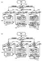
- FIG. 7A is an operation flowchart of the transmission side communication apparatus 110 according to the present embodiment.
- the determination unit 114 of the transmission-side communication device 110 determines the method of transmitting the abnormality information to the other device based on the determination condition of FIG.
- the determination unit 114 selects the power state of the other device (the receiving communication device 120) from the power state of each device stored in the power state storage unit 113 (S701).
- the determination unit 114 further selects the type of abnormality information to be notified from the abnormality information for each type stored in the information type storage unit 112.
- the determination unit 114 determines that the power supply state is the main power supply activation state and the type of the abnormality information is the information A or the information B (S702a), the abnormality information is transmitted by the protocol processing (S703). On the other hand, when it is determined that the type of the abnormality information is the information C (S702a), an instruction to cut off the main power of the partner device is issued (S704). If the determination unit 114 determines that the power supply state is only the communication adapter activation state and the type of the abnormality information is the information A (S702 b), as shown in FIG. Transmission of abnormality information by protocol processing is performed (S 705).
- the non-volatile storage in the receiving communication device 120 is not performed as shown in FIG.
- a message instructing writing of abnormal information to the part 123 is transmitted (S706).
- the content analysis of the anomaly information that is, the protocol processing is not performed by the partner device.
- the determination unit 114 determines that the power supply state is the standby power 0 state and the type of the abnormality information is the information A (S702 c), as shown in FIG. As in the case of No. 4, the start instruction of the main power supply of the partner device is issued, and the abnormal information is transmitted by the protocol processing (S707).
- the type of the abnormality information is information B or information C (S702c), as shown in FIG. 6, after instructing to start the communication adapter of the partner device, as in FIG. Without activating, a message instructing writing of abnormal information to the non-volatile storage unit 123 in the receiving communication device 120 is generated and transmitted (S 708).
- S 708 content analysis of abnormality information, that is, protocol processing is not performed by the other device.
- FIG. 7B is an operation flowchart of the receiving side communication device 120 according to the present embodiment.
- the reception-side communication device 120 controls activation control and write control based on the power supply state of the device itself and the type of the received abnormality information.
- the information processing unit 121 performs processing corresponding to each information from the power supply state (S 711) of the reception side communication device 120 and the abnormality information received from the transmission side communication device 110. Assuming that the power supply state is the main power supply activation state and the type of the received abnormality information is the information A or the information B (S712a), the abnormality information by the protocol process is received (S713).
- the main power control unit 125 controls to cut off the main power of the receiving communication device 120 (S714). Assuming that the power supply state is only the communication adapter activated and the type of the received abnormality information is information A (S 712 b), as shown in FIG. 4, the main power supply control unit 125 controls the main power supply to be activated. , Receives abnormality information by protocol processing (S 715). On the other hand, assuming that the type of the received abnormality information is information B or information C (S 712 b), as shown in FIG.
- the abnormality information message is received and the abnormality in the volatile storage unit 123 by the writing control unit 124
- the information writing process is performed (S716).
- content analysis of the received message that is, protocol processing is not performed.
- the power supply state is the standby power 0 state and the type of the abnormality information is the information A (S 712 c)
- the main power supply control unit 125 is activated as in FIG. 4 after the communication adapter 120 a is activated as shown in FIG.
- the abnormal information by the protocol processing is received (S717).
- the type of abnormality information is information B or information C (S 712 c)
- the communication adapter 120 a is instructed to start, reception of abnormality information and writing control as in FIG.
- the content analysis of the received message that is, the protocol processing is not performed.
- each device has the configuration of both the transmitter communication device 110 of FIG. 1 (b) and the receiver communication device 120 of FIG. 1 (c). It may be for example, in addition to the case where abnormality information is notified from the HGW to the DTV or the white goods, or when the abnormality information is notified from the DTV or the white goods to the HGW, the means described in this embodiment is used. It is possible.
- the power of the other device is cut off by determining the method of transmitting the abnormal information from the power state of the other device to which the abnormal information is notified and the type of the abnormal information. Even in the case where it is done, reliable information transmission is possible.
- FIG. 8A shows an example of a basic operation sequence at the time of distribution of recall information.
- the recall information when the recall information is transmitted from the ASP server to the HGW, the ASP server operates as the transmitting communication device 110 in FIG. 1B and the HGW operates as the receiving communication device 120 in FIG. .
- the recall information when the recall information is transmitted from the HGW to the white goods, the HGW operates as the transmission side communication device 110 of FIG. 1 (b) and the white goods as the reception side communication device 120 of FIG. 1 (c).
- the recall information in FIG. 8A is assumed to be recall information leading to a serious accident with high urgency and to stop the use of the corresponding home appliance together with the information notification to the user.
- FIG. 8A when white goods (for example, an air conditioner) is turned off by the operation of the user, end notification information is transmitted.
- white goods home appliances perform communication processing according to the ECHONET (TM) standard, transmit status information on a broadcast (multicast) basis, and notify power status information.
- the HGW updates the information in the power state storage unit.
- the HGW checks whether or not the latest information exists for the ASP server at regular intervals. At this time, a method using SOAP (Simple Object Access Protocol) mainly based on HTTP may be used.
- SOAP Simple Object Access Protocol
- the HGW to store device information of DTVs and white goods at home.
- the white goods are in a state where the main power supply is asleep and only the communication adapter is in operation, and the type of the abnormal information to be notified is the information for prohibiting the power supply activation of the other device. Because of this, it generates and sends a message instructing information recording to the non-volatile storage unit of the white goods.
- FIG. 8B shows a communication message for transmitting recall information transmitted by the ASP server.
- the recall information message is composed of a TCP / IP header and a protocol message.
- the protocol message includes a maker ID, a product ID, a serial number, a recall ID, a recall rank, and operation prohibition information.
- the maker ID, the product ID, and the serial number indicate the device type, and are used to specify the device as in the case of FIGS. 3B and 3C.
- the recall ID, recall rank, and operation prohibition information indicate a recall type.
- the recall ID is an identification code uniquely assigned to each occurrence of a recall.
- the recall rank indicates information on safety and thorough notification.
- the operation prohibition information is used to forcibly stop the use of the device when it is dangerous to operate the corresponding device, and the operation prohibition is made in the valid state, and the operation is permitted in the invalid state.
- the operation inhibition information is indicated by a bit value, and is designated as a value of "1" when in the valid state, and a value of "0" when in the invalid state. Needless to say, negative logic may be used other than positive logic.
- FIG. 8A after the abnormality information whose operation prohibition information has become valid is recorded in the non-volatile storage unit of the white goods, when the user performs an operation or a start by a timer, the device is non-volatile at the time of start initialization processing. If the information in the nature storage unit is confirmed and it is confirmed that the abnormal information (protocol message) in which the operation prohibition information is valid is recorded, the operation is immediately prohibited and the main power supply is disconnected.
- the present embodiment is not limited to the above-described configuration, and in the implementation stage, the present invention can be applied even if the components are modified without departing from the scope of the invention.
- various inventions can be formed by appropriate combinations of a plurality of components described in the above embodiment. Also, some components may be deleted from all the components shown in the embodiment. Furthermore, components in different embodiments may be combined as appropriate. For example, as shown in FIG. 8C, in this embodiment, communication between AV / white goods with HGW-A, B, C as a center (for example, home communication), HGWA, B, C and ASP server It has shown that it is applicable to communication etc. between.
- (A) shows that the HGW is always in the power supply operating state, but in fact, the HGW can also be put into the sleep state, and state information is sent to the ASP server every time the power state changes. Notification, power activation control from the ASP server via the Internet, and writing of information to the non-volatile storage unit may be performed.
- the HGW exists as individual independent devices, and may be realized as a software program embedded in a home appliance such as a DTV.
- FIG. 8C as the communication without passing through the HGW device, an implementation form in which the HGW function is incorporated in the DTV is shown in items 7 to 11.
- the ASP server notifies recall information and analysis information on abnormality to the DTV having the HGW function, and performs notification processing to the white goods from the DTV or display processing of the analysis result on its own screen.
- this embodiment can be applied comprehensively in communication between devices and between devices and a server on the Internet.
- the present invention is also disclosed in a system that transmits control instruction information such as a reservation operation, as well as abnormality information such as equipment failure and recall, and executes predetermined processing when the power supply of the equipment is activated. It is possible to apply the following method.
Landscapes
- Engineering & Computer Science (AREA)
- Automation & Control Theory (AREA)
- Computer Networks & Wireless Communication (AREA)
- Signal Processing (AREA)
- Telephonic Communication Services (AREA)
- Small-Scale Networks (AREA)
Abstract
機器の故障やリコールに関する異常情報を伝達する通信システムにおいて、情報を通知する機器の主電源が起動していない状況においても、確実な情報伝達を実現するために、本発明の通信装置は、機器の異常状態を検出し異常情報を生成する情報生成部と、異常情報の通知相手となる機器の電源状態を記憶する電源状態記憶部と、異常情報を種別毎に記憶する情報種別記憶部と、電源状態と異常情報の種別から、異常情報の伝達方法を判定する判定部と、この伝達方法で通知相手機器に対する異常情報を送信する通信処理部とを備える。この構成により、機器の省電力性を考慮しつつ、確実な情報伝達と機器制御を実施することが出来る。
Description
本発明は、通信装置および通信方法に関する。
機器の異常発生に関する情報を機器同士、あるいは機器とインターネット上のサーバ間で送受信し、最終的にユーザに対する解決手段を提供するシステムを想定する。異常情報とは、機器内部の故障に関する情報や、ユーザの誤操作によるエラー情報、機器製造ベンダからのリコール情報などを含んでいる。また、異常情報は、機器の故障を予兆診断するために、機器内部の動作履歴をインターネット上のサーバに送信するログ情報や、ログ情報の分析結果をユーザに提示するための分析情報も含めることとする。
特許文献1では、ガス異常発生時などに、利用者の介在なくテレビを自動起動させ、緊急情報を表示するシステムが提案されている。また、特許文献2では、電気機器の利用者が作業を行うことなく、故障に関する情報をインターネット上のサーバに自動的に登録するシステムが提案されている。しかし、これらの従来の技術においては、通知すべき異常情報と各々の機器の省電力に関する電源状態とが適切に考慮されていない問題がある。宅内のDTV(Digital Television)や白物家電などの機器上で記録可能な情報量には制限があるため、情報が発生次第、インターネット上のサーバを含む他機器に対して通知することが望ましいが、省電力のため主電源が切断されている相手機器に対して情報を通知する場合には、定期的なログ情報のように相手の主電源を起動させてまで緊急に通知を行う必要のない情報の伝達に関しては処理が無駄となることや、白物家電機器のリコール事故のように相手機器の主電源を起動させると逆に危険な状況が発生してしまう状況に対処することが出来ない。また、従来の技術では、送信側が情報伝達に成功するまで稼動を継続する必要があるため、省電力性の観点からも非効率的な処理となり得る。
また、従来の技術は、通知先の機器の主電源が切断された状態になっているものの、通信処理部には一定量の電力が継続的に供給されている状態を前提としているため、機器の待機電力を極限まで落とした上での情報伝達手段が考慮されておらず、消費電力効率が悪い問題が考えられる。尚、特許文献3では、無線信号を受信して、機器の状態を移行させるためのトリガ信号を発生するトリガ信号発生装置が提案されており、機器の主電源が切断されている状態においては、待機電力がほとんど発生しないことが特徴である。但し、トリガ信号発生装置自身は、他の機器との間で通信処理を行うことは出来ない。
上述したように、従来技術には通知すべき異常情報と各々の機器の省電力に関する電源状態とが適切に考慮されていない問題があった。また、従来技術における機器の通信処理部には電力が継続供給されている状態を前提としているため、機器の待機電力を極限まで落とした上での情報伝達手段が考慮されておらず、消費電力効率が悪い問題があった。
本発明は、上記問題を解決するためになされたものであって、異常情報を通知する相手機器の電源状態と異常情報の通知優先度を元に異常情報の伝達方法を判定し、異常情報を伝達する先の機器の電源が切断されている場合においても確実な情報伝達を実現可能にする通信装置、通信方法を提供することを目的とする。
本発明は、上記課題を解決するために、機器の異常状態を検出し異常情報を生成する情報生成部と、前記異常情報の通知相手となる機器の電源状態を記憶する電源状態記憶部と、前記異常情報を種別毎に記憶する情報種別記憶部と、前記電源状態と前記異常情報の種別から、前記異常情報の伝達方法を判定する判定部と、前記伝達方法で前記通知相手機器に対する前記異常情報を送信する通信処理部とを備えることを特徴とする。
本発明によれば、異常情報を通知する相手機器の電源状態と異常情報の通知優先度を元に異常情報の伝達方法を判定することにより、相手機器の電源が切断されている場合においても確実な情報伝達が可能になる。
以下、本発明の実施形態について図面を用いて説明する。
(第1の実施形態)
図1に本実施形態における異常情報の伝達に係わる通信システムの構成を示す。DTVや白物家電はそれぞれ通信インターフェースを有し、他の機器との間でメッセージの送受信を行うことが可能である。ここで、冷蔵庫や洗濯機、エアコンといった白物家電に関する通信規格としてはECHONET(TM)が存在する。ECHONET(TM)規格の手順に従うことで、ネットワークを介して照明やエアコン等の遠隔制御、監視、連携動作等が可能となる。また、DTVやPC(Personal Computer)、HDD(Hard Disk Drive)レコーダ等のAV(Audio Visual)家電に関する通信規格としてはDLNA(Digital Living Network Alliance)(TM)が存在する。DLNA(TM)規格に準拠することで、ネットワーク上のHDDレコーダに保存された映像コンテンツを、DTVでストリーミング再生することなどが可能となる。DLNA(TM)はメッセージの制御系メッセージの送受信に関しUPnP(TM)を利用しており、UPnP(TM)では機器同士の制御命令や、イベント情報の通知に関する基本的な枠組みが取り決められている。DLNA(TM)に対応したDTVとECHONET(TM)に対応した白物家電同士が直接メッセージのやり取りを行うことは不可能であるため、HGW(Home Gateway)と呼ばれる、異なるプロトコル同士を相互に変換するゲートウェイ機器が必要となる。図1(a)において、例えば、ユーザはDTV101の表示画面を介して、宅内の照明機器やエアコンといった白物家電102の制御を行うことが可能となる。この場合、DTV101から送信されたUPnP(TM)メッセージは、HGW103で一旦受信され、プロトコル情報の解析とECHONET(TM)メッセージへと変換処理を行った後、対応する白物家電102に対して通知処理を実施する。
(第1の実施形態)
図1に本実施形態における異常情報の伝達に係わる通信システムの構成を示す。DTVや白物家電はそれぞれ通信インターフェースを有し、他の機器との間でメッセージの送受信を行うことが可能である。ここで、冷蔵庫や洗濯機、エアコンといった白物家電に関する通信規格としてはECHONET(TM)が存在する。ECHONET(TM)規格の手順に従うことで、ネットワークを介して照明やエアコン等の遠隔制御、監視、連携動作等が可能となる。また、DTVやPC(Personal Computer)、HDD(Hard Disk Drive)レコーダ等のAV(Audio Visual)家電に関する通信規格としてはDLNA(Digital Living Network Alliance)(TM)が存在する。DLNA(TM)規格に準拠することで、ネットワーク上のHDDレコーダに保存された映像コンテンツを、DTVでストリーミング再生することなどが可能となる。DLNA(TM)はメッセージの制御系メッセージの送受信に関しUPnP(TM)を利用しており、UPnP(TM)では機器同士の制御命令や、イベント情報の通知に関する基本的な枠組みが取り決められている。DLNA(TM)に対応したDTVとECHONET(TM)に対応した白物家電同士が直接メッセージのやり取りを行うことは不可能であるため、HGW(Home Gateway)と呼ばれる、異なるプロトコル同士を相互に変換するゲートウェイ機器が必要となる。図1(a)において、例えば、ユーザはDTV101の表示画面を介して、宅内の照明機器やエアコンといった白物家電102の制御を行うことが可能となる。この場合、DTV101から送信されたUPnP(TM)メッセージは、HGW103で一旦受信され、プロトコル情報の解析とECHONET(TM)メッセージへと変換処理を行った後、対応する白物家電102に対して通知処理を実施する。
本実施形態においては、機器の異常発生に関する情報を機器同士、あるいは機器とインターネット上のサーバ間で送受信し、異常に対する解決手段をユーザに提示するシステムを想定している。そのため、図1(a)で示す通信システムの構成をより詳しく解説する。白物家電(例えば洗濯機)102が当該機器内の異常を検出した場合、HGW103に異常情報を通知する。HGW103はインターネット上のASP(Application Service Provider)サーバ104に対して、一定期間情報を蓄積した後に異常情報を送信、あるいはイベント発生時に即座に異常情報を送信、のいずれかの手段を用いて通知する。ASPサーバ104側では、HGW103から送信された異常情報に含まれる異常種別を解析し、機器の部品故障による異常発生なのか、ユーザの誤操作による異常発生なのかといった分析処理を実施する。サーバの解析結果となる分析情報は、HGW103が一定周期毎に問い合わせ、あるいはASPサーバ104からHGW103側に通知のいずれかの手段によって、ASPサーバ104からHGW103に伝達される。HGW103は受信した分析情報を元に、例えばDTV101に対して詳細な分析結果情報を表示させ、異常に対する解決手段をユーザに提示する。この場合、インターネット上の公開リソースとして、URL(Uniform Resource Locator)を提示し、Webブラウザで詳細情報を表示させることも考えられる。また、リコール情報を通知する場合は、HGW103は該当する機器に対して直接情報を通知し、機器のLEDランプの点滅やブザーの鳴動等を通じて、問題のある機器であることをユーザに通知する。更に、機器の動作ログ情報をASPサーバ104側で解析し、故障の予兆診断に利用する応用も考えうる。この場合も、ASPサーバからHGWへの分析情報の伝達、およびDTVなどの表示機器への通知も同様に実施可能である。
このように、機器の異常情報や動作ログ情報、リコール情報を機器同士、あるいは機器とインターネット上のサーバ間で送受信することによって、家電機器の品質向上に貢献することが可能となる。しかしながら、DTVのように利用時のみ電源起動するような機器も少なくない。情報を伝達する先の機器の電源が切断されている場面においては、上述した情報伝達を実施することは不可能である。そのような問題を鑑み、本実施形態の手段を適用することによって、異常情報の送信側の機器が、情報を通知する相手機器の電源状態と異常情報の通知優先度を元に異常情報の伝達方法を判定することにより、相手機器の電源が切断されている場合においても確実な情報伝達が可能になる。本実施形態に関する詳細について、装置構成や通信シーケンス、動作フローチャートを用いて説明する。
図1(b)は、本実施形態に係わる送信側通信装置110を示すブロック図である。送信側通信装置110は、情報生成部111、情報種別記憶部112、電源状態記憶部113、判定部114、プロトコル処理部115、書込指示部117、起動指示部116、通信部118、第1通信処理部118a、第2通信処理部118bを備える。情報生成部11は、送信側通信装置110がDTVや白物家電機器の場合は、機器内部の部品故障やユーザの誤操作によるエラーを検出し異常情報を生成する。また、機器の動作状態を定期的に取得しログ情報を生成する。一方、送信側通信装置110がASPサーバである場合は、受信した異常情報を元に分析処理を行い、異常に対する解決方法を分析情報として生成するほか、機器のリコールに関する情報、機器の電源起動を制御するための情報等も生成する。更に、送信側通信装置110がHGWである場合は、HGW自体の故障やエラーを含む異常情報に加えて、DTVや白物家電機器から収集した異常情報、ASPサーバから収集した分析情報が生成対象となる。
情報種別記憶部112は、情報生成部111によって生成された異常情報を種別毎に記憶する。例えば異常情報は、通知に緊急を要する情報(情報A)、通知に緊急を要さない情報(情報B)、電源起動を禁止する情報(情報C)の3種類の種別に分類する。情報Aとしては、例えば、ASPサーバからのリコール通知や、家電機器の異常発生時の異常情報等である。また、異常情報を元に解析、生成される分析情報も故障修理のように対応を早急に行うべき場合は、情報Aとして分類することが望ましい。情報Bとしては、機器が定期的に収集し、HGWを介してASPサーバに通知される各機器のログ情報など、対応するタイミングを一定時間後に先送りしても問題のない場合は、情報Bとして分類することが望ましい。情報Cに関しては、重大な事故につながるような、対応を徹底すべきリコールが発生した場合に、該当する家電機器の利用を強制的に停止させるために用いる。異常情報と種別の対応付けは、上述のものに限定する必要はなく、異常情報の送信側通信装置110が状況に応じて判断する方法にも適用できる。
電源状態記憶部113は、異常情報を通知すべき相手機器の電源状態を記憶する。本実施形態において、電源状態は、主電源起動、通信アダプタのみ起動、待機電力0状態の3種類の状態に分類する。主電源起動の場合は、UPnP(TM)やECHONET(TM)による通信プロトコル処理に加え、情報生成部111による分析処理等も実行可能な状態である。通信アダプタのみ起動の場合は、例えば、IEEE802.3による有線通信処理やIEEE802.11による無線通信処理のみが基本的に実施可能で、OS(Operating System)を含めた機器の主要な機能は休眠状態となっており、複雑なプロトコル処理やアプリケーション処理を実施することは不可能な状態である。本発明におけるプロトコル処理とは、UPnP(TM)やECHONET(TM)によるメッセージ通信処理のことを意味するものとする。通信アダプタのみ起動の場合も、情報を送受信すること自体は可能である。但し、通信アダプタのみ起動している状態の受信機器では、UPnP(TM)におけるXML(eXtensible Markup Language)ドキュメントのような、複雑なメッセージ情報を解析することは出来ないものとする。待機電力0状態は、特許文献3で開示されたシステムのように、特定の信号を受信して、機器の状態を移行させるためのトリガ信号を発生するトリガ装置のみが動作しており、待機電力はほとんど無視することが出来るが、上述のようなIEEE802.3による有線通信処理やIEEE802.11による無線通信処理による伝送手順を実施することすら出来ない状態である。主電源も切断中の状態である。他機器の電源状態の取得方法は、例えば、UPnP(TM)による通信の場合は、機器の終了メッセージ中に電源状態を付加することによって実現できる。ECHONET(TM)による通信の場合は、動作状態取得に関するメッセージを用いることで、本体部の電源状態に関する情報を通信アダプタ部から取得することができる。また、HGWとASPサーバ間では、HTTP(Hyper Text Transfer Protocol)によるメッセージ送受信を用いて通知する方法などある。
判定部114は、情報種別記憶部112と電源状態記憶部113との情報から、異常情報の伝達方法を判定する。ここで、図2は、送信側通信装置110の判定部114が用いる判定テーブルを示している。電源状態記憶部の情報と情報種類記憶部の情報とから情報の伝達方法は一意に決定される。図2における各々の伝達方法に関しては、図3から図6を用いて後述する。
プロトコル処理部115は、UPnP(TM)やECHONET(TM)によるプロトコルメッセージの生成と送信によって異常情報の伝達を行う。書込指示部117は、異常情報の通知相手機器の主電源が切断されており、通信アダプタのみ起動している場合に、この異常情報の不揮発性記憶部への記録を指示するメッセージの生成と送信を行う。不揮発性記憶部への記録を指示するメッセージは、固定の情報要素から構成され、複雑な内容の解析も不要であるため、プロトコル処理部の介在は不要である。相手機器は、機器の主電源を起動させることなく、通信アダプタを介して受信した異常情報の記録のみ行い、ユーザの操作による主電源起動や、一定期間毎の主電源起動の際に、情報の取得とプロトコル処理、あるいはアプリケーション処理を実施する。起動指示部116は、特許文献3に開示されたシステムのように、特定の信号を生成して送信し、相手機器の状態を移行させる制御を行う。すなわち、相手機器において、特定の信号を受信してトリガ信号を発生させる第1通信処理部と、IEEE802.3による有線通信処理やIEEE802.11による無線通信処理による伝送制御を行う第2通信処理部とで構成され、送信側通信装置110は、相手機器が待機電力0状態(主電源と第2通信処理部の双方が休眠状態)の場合に、相手機器の第2通信処理部を起動させるための信号を生成して、相手機器の第1通信処理部に向けて送信する。第1通信処理部と第2通信処理部とは必ずしも物理的に分離された要素である必要はなく、1つの通信処理部内での動作状態を「送受信可能状態」「トリガ信号のみ受信可能状態」とした上で通信部を構成する方法も考えられる。
送信側通信装置110の第1通信処理部118aは、相手機器の第1通信処理部と通信する。すなわち、特定の信号を受信した場合に、機器の状態を変更させるトリガを発生させる通信処理部に対して、特定の信号を生成して送信する。第1通信処理部118aは無線による信号送信を行っても、有線による信号送信を行っても良い。第2通信処理部118bは、IEEE802.3による有線通信処理やIEEE802.11による無線通信処理を実施する。すなわち、異常情報のメッセージ送受信に関しては、第2通信処理部118bを介して実施する。但し、IEEE802.3やIEEE802.11に限定されるものではなく、FDDI(Fiber Distributed Data Interface)のように他の通信手段を用いても良いことは言うまでもない。第1通信処理部118aと第2通信処理部118bは、通信部118によって制御される。具体的には、異常情報や異常情報書込指示要求の送信時には第1通信処理部118aを選択して送信し、相手機器の起動指示メッセージを送信する場合には第2通信処理部118bを選択して送信する。
図1(c)は、本実施形態に係わる受信側通信装置120を示すブロック図である。受信側通信装置120は、情報処理部121、プロトコル処理部122、不揮発性記憶部123、書込制御部124、主電源制御部125、通信部126、第1通信処理部126a、第2通信処理部126bから構成される。情報処理部121は、送信側通信機器120から受信したリコール通知や異常情報、分析情報、定期ログ、電源起動を禁止する情報を受信した場合に、それぞれの情報に対応した処理を行う。すなわち、異常情報を受信した場合は分析処理を行う。分析情報を受信した場合は、例えばDTVが受信側通信装置120であれば分析結果を画面に表示する処理を行う。定期ログを受信した場合であれば、ログ情報を解析し、故障の予兆診断等を行う。電源起動を禁止する情報を受信した場合は、主電源の切断処理を開始する。
プロトコル処理部122は、送信側通信装置120と同様、UPnP(TM)やECHONET(TM)等によるプロトコルメッセージの生成、解析や送受信処理を行う。不揮発性記憶部は、例えばNAND型フラッシュメモリ等によって実現される。書込制御部124は、送信側通信装置120の指示によって、異常情報を含むプロトコルメッセージの記録を不揮発性記憶部123に対して実施する。書込制御部は複雑なプロトコル処理を実施しないため、内容の解析は行わず、受信したメッセージを記録する処理のみを実施する。主電源制御部125は、特定のパターンを含む情報を受信した場合に、機器の主電源を起動する処理を行い、例えば、WoL(Wake on LAN)によるマジックパケットの受信処理等によって実現される。本実施形態において、書込制御部124や主電源制御部125による処理は、通信アダプタ内部の処理として取り扱い、通信アダプタの電源が起動している場合に実施可能である。通信部126は、第1通信処理部126aと第2通信処理部126bを含む。第1通信処理部126aは、特定の信号を受信した場合に、機器の状態を変更させるトリガ信号を生成する通信部126として動作する。具体的には、通信アダプタ120aとして動作する第2通信処理部126bの電源を起動、機器本体の主電源を起動などの制御を行う。第1通信処理部126aは無線による信号受信、有線による信号受信のいずれの手段を用いても良い。第2通信処理部126bは、IEEE802.3による有線通信処理やIEEE802.11による無線通信処理を実施し、異常情報を含むプロトコルメッセージの送受信処理を行う。送信側通信装置110の場合と同様、実現形態はIEEE802.3やIEEE802.11だけではなく、FDDI等他の通信方式を用いても良いことは言うまでもない。また、第1通信処理部と第2通信処理部は必ずしも物理的に分離されている必要はなく、前述のように、1つの通信処理部が「送受信可能状態」「トリガ信号のみ受信可能状態」と複数の状態で動作可能である場合も考えられる。本実施形態において、待機電力0状態とは、第1通信処理部126aのみが稼動している状態を示す。通信アダプタのみ起動している状態とは、第1通信処理部126aと第2通信処理部126bを含む通信部126、書込制御部124、不揮発性記憶部123、主電源制御部125が稼動している状態を示す。主電源起動状態とは、情報処理部やプロトコル処理部といった主要な機能まで含めて稼動しており、受信した異常情報に対する分析処理を実行可能な状態である。
図3を用いて、異常情報の通知相手機器の主電源が起動している状態における基本的な動作シーケンスと通信メッセージの構成を説明する。この状態は、図2における相手機器電源状態が主電源起動で、異常情報の種別が情報Aと情報Bである場合に対応する。図3(a)は、HGWからDTVに対して異常情報を伝達する場面を示している。例えば、図1に示す白物家電において、ユーザの誤操作によるエラーや機器部品に故障が発生した場合に、白物家電はHGWを介してASPサーバやDTVに情報を伝達する。ここで、図3(a)における異常情報は、機器に発生した異常状態を示す情報(エラーや部品故障)に加え、ASPサーバからのリコール通知や分析情報なども含む広義の意味で取り扱うものとする。UPnP(TM)規格にて既定されている通信手順に従う例を想定すると、DTVはHGWに対して、イベント発生時にイベント情報を送信してもらうためのイベント登録メッセージを送信する方法がまず考えられる。イベント登録メッセージをHGWが受信した後、異常情報(エラーや故障の異常情報、分析情報、リコール通知など)が発生した場合に、異常情報の送信処理を行う。異常情報の送信は、通常、IP(Internet Protocol)マルチキャスト伝送方式によって、同一種別のイベント情報受信を待つ複数の機器に対して情報を伝達する。この他、HGWからDTVに対して制御要求メッセージをIPユニキャストにて送信し、個別の機器毎に情報を伝達する方法も考えうる。ECHONET(TM)規格の場合も同様に、ブロードキャストベースの情報伝達やユニキャストベースの情報取得といった実現形態が適用可能である。図3(a)において、DTVはHGWから異常情報を受信した後、情報の解析を行い、必要に応じて画面への表示処理を実施する。また、図3(a)では、HGWからDTVに対して異常情報の伝達を行っているが、逆方向としてDTVからHGWに対して異常情報(この場合は、エラーや故障の異常情報が主に該当)を伝達する場面においても、同様の手順を用いることが可能である。HGWは異常情報を受信すると、ASPサーバへの情報伝達を実施する。更に、異常情報の伝達ではないが、DTVから白物家電に対する制御命令(エアコンの起動や照明の点灯)を通知する場合にも、同様の手順を適用することが可能である。
図3(b)、(c)は、本実施形態における異常情報を含む通信メッセージの構成を示している。基本的な構成は同じだが、図3(b)はエラーや部品故障による異常情報と異常に対する分析情報、図3(c)は機器が定期的に取得するログ情報を含むメッセージである。図3(b)において、通信メッセージは、TCP/IP(Transmission Control Protocol / Internet Protocol)ヘッダ部とプロトコルメッセージ部から構成される。実際には、ネットワーク上で伝送される際は、IEEE802.3やIEEE802.11等におけるMAC(Medium Access Control)ヘッダ部が付加された上で物理層伝播が行われるが、本実施形態における説明においては説明を省略する。図3(b)のプロトコルメッセージは、UPnP(TM)規格の場合、XML(eXtensible Markup Language)ドキュメントによる構造化文書によって実現される。そして、本実施形態における異常情報を示すプロトコルメッセージ(XMLドキュメント)は、メーカーID(IDentifier)、商品ID、製造番号、異常ID、異常メッセージ、分析ID、分析メッセージなどの情報を含む。メーカーID、商品ID、製造番号は機器種別を示す。メーカーIDは機器の製造会社を一意に識別するための情報である。商品IDはDTVやエアコン、HGWといった機器の商品形態を識別するための情報である。製造番号は、出荷される製品に付けられる一続きの番号で、製品毎に固有の番号が割り当てられており、メーカー側で所有者を管理する際や商品の偽装を防止する目的で使用される他、リコールなどの問題が発生したときの参照に利用される。異常ID、異常メッセージは異常種別を示す。異常IDは、メーカー毎に定められたエラーコードを特定するために用いる。異常メッセージは、機器の部品故障に関する情報などの文字情報によって構成される。分析IDと分析メッセージは、分析種別を示す。分析IDは、異常に対する診断結果をメーカー毎に定めた識別コードである。例えば、機器の故障発生に関する異常情報の場合は、機器の利用が継続的に可能であるかどうか、サポートセンターへの連絡が必要かどうかといった分析結果情報が対応する。分析メッセージは、分析IDに関する情報を文字情報によって構成したもので、例えば、DTVに表示する分析情報や、より詳細な情報を閲覧するためのWebサーバへのURL(Uniform Resource Locator)情報などが含まれる。異常種別に関する情報と分析種別に関する情報は両方併せて1つの通信メッセージを形成しても良いし、どちらか一方を省略しても良い。UPnP(TM)規格による通信の場合は、XMLを用いて可変長のメッセージを利用可能としていたが、ECHONET(TM)規格による通信を行う場合は、固定長のフィールドから構成されるメッセージ構成を取っても良い。図3(c)は、機器が定期的に取得するログ情報を含む通信メッセージを示しており、メーカー毎に定められたログレベルを識別するためのログIDと、ログメッセージの文字情報から構成される。機器が複数のログ情報を蓄積することを勘案し、図3(c)におけるログID、ログメッセージは複数含めることが可能である。機器種別に関する情報は、図3(b)と図3(c)で同様の意味を持つものである。
図4を用いて、異常情報の通知相手機器の主電源が休眠状態で、通信アダプタのみ起動状態における、通知に緊急を要する動作シーケンスと通信メッセージの構成を説明する。これは、図2の相手機器電源状態が通信アダプタのみ起動、異常情報の種別が情報Aに該当する。リコールや機器の部品故障等、緊急性の高い異常情報は、ユーザに対して早急に通知する方が望ましい。しかし、実際の運用上、全ての機器が常時主電源稼動状態になっている状況は少ない。主電源が起動していれば、アプリケーション処理やプロトコル処理といった主要な処理を実施することが可能であるが、その反面、より多くの消費電力が必要となる。そのため、通信アダプタのみ稼動し、必要に応じて機器の主電源を起動、その上で異常情報を通知する方法が効果的である。これを実現する手段としては、WoL技術が挙げられる。WoLはコンピュータネットワークに接続されているコンピュータの電源制御(主電源起動、主電源切断)を遠隔で操作するための技術である。通信アダプタには必要最低限の電力が供給され、特定のパターンを含む通信メッセージを受信した場合に、主電源の起動処理や切断処理を実施する。
図4(a)は、異常情報の通知相手機器の主電源が切断されており、通知に緊急性を要する場合の動作シーケンスを示している。図4(a)の上段では、図3(a)の場合と同様に、通知相手機器であるDTVの主電源が起動している状態において、HGWからイベントメッセージの送信が行われている。その後、ユーザの操作により、DTVの主電源が切断される時点で、切断処理が完了する前に終了通知を送信する。UPnP(TM)規格による通信を行う場合、機器がネットワークから不在となることを通知するメッセージは、複数の機器を宛先対象としたIPマルチキャストによって実現される。またこの際、プロトコルメッセージ中に、電源状態に関するより詳細な情報を付加することが望ましい。具体的には、図4(a)で示したような、主電源が休眠しており通信アダプタのみ稼動している状態のほか、詳細は後述するが、本実施形態においては、主電源と通信アダプタの両方が休眠して特定のトリガ信号のみを待ちうける状態も存在するため、これらを区別するためには、電源状態情報を付加することが有用である。図4(a)において、DTVから終了通知メッセージを受信したHGWは、電源状態記憶部の情報を更新し、DTVの状態を通信アダプタのみ稼動状態として記憶する。終了通知メッセージは、上述のように、IPマルチキャストベースで実現しても良いが、制御メッセージとして機器毎にIPユニキャストで情報を通知する方法を用いても良い。
図4(a)において、DTVの主電源切断後に、HGW上で異常情報が発生した場合、判定部114が情報種別記憶部112と電源状態記憶部113との情報を基に判定処理を行い、HGWはDTVの通信アダプタに対して主電源の起動を指示するためのメッセージを生成して送信する。図4(b)は、相手機器の主電源を起動させるための通信メッセージ例としてWoLマジックパケットの構成を示している。WoLマジックパケットは、UDP/IP(User Datagram Protocol/Internet Protocol)ヘッダ部、同期用識別子、起動機器MACアドレスから構成される。主電源が切断状態の受信側通信装置120の通信アダプタ120aは、通信メッセージの受信処理を行い、メッセージ中に含まれるWoL制御用の特定シーケンスで構成される同期用識別子が存在するか否かを解析する。同期用識別子が存在しない場合は、電源制御に関する処理は行わない。同期用識別子を認識した場合、識別子に続いて制御対象の通信アダプタのMACアドレスが特定回数分連続して付加される。通信アダプタのMACアドレスと起動機器MACアドレスが一致しない場合も、電源制御に関する処理を行わない。ここで、通信アダプタのMACアドレスとは、第2通信処理部126bのMACアドレスのことを示している。通信アダプタが同期用識別子に続いて、自身のMACアドレスに合致する起動機器MACアドレスを認識した場合は、主電源の起動処理を開始する。図4(a)において、主電源が起動したDTVは、HGWに対して、イベント通知メッセージを受信するためのイベント登録処理を行う。HGW側では、その時点で、通知すべき異常情報を蓄積しているため、イベント通知メッセージを直ちに送信する。異常情報を受信したDTVは、図3(a)における実施形態と同様、情報解析処理を行った上で画面への表示を行う。前述のように、異常情報の通知はイベント発生時にIPマルチキャストベースの伝達方法を用いる他、制御メッセージを用いて個々の機器にIPユニキャストベースで伝達する方法を用いても良い。ECHONET(TM)規格の場合も同様に、ブロードキャストベースの情報伝達やユニキャストベースの情報取得といった実現形態が適用可能である。また、DTVが主電源を切断する前に送信する終了通知メッセージが伝送路上のエラーによって廃棄された場合、停電等によってDTVの電源が不意に切断された場合は、送信側通信装置が把握する電源状態と、実際の電源状態との整合性が取れないため、プロトコルメッセージの送信に失敗した場合は、相手機器の電源状態を省電力アダプタのみが稼動している待機電力0状態とみなして以後の処理を実施することが望ましい。
図5は、異常情報の通知相手機器の主電源が休眠しており通信アダプタのみ稼動している状態において、通知に緊急を要さない情報を送信する場合の動作シーケンスと通信メッセージの構成を示している。機器の動作状態に関するログ情報や、ユーザの誤操作によるエラーの分析情報などは、通知先の機器の主電源を起動させてまで通知する必要がない情報と考えられる。ここで、白物家電のリコールのように相手機器の主電源を起動させると逆に危険な状況が存在する問題がある。また、送信側が情報伝達に成功するまで稼動を継続して情報を蓄積することや、場合によっては再送を継続することから、情報蓄積の信頼性や省電力性の観点から非効率である問題が考えられる。そこで、本実施形態における送信側通信装置110の判定部114は、相手機器電源状態が通信アダプタのみ起動している状態で、かつ異常情報の種別が情報B、あるいは情報Cである場合は、相手機器の主電源の起動を行わずに、受信側通信装置120内部の不揮発性記憶部123への情報書き込みを指示するメッセージを生成して送信する。
図5(a)は、相手機器の主電源を起動させずに不揮発性記憶部123への情報書き込みを指示する場合の動作シーケンスを示している。図4(a)における、相手機器への主電源起動指示の場合と同様に、送信側通信装置110は、相手機器の電源状態が遷移することを終了通知メッセージの受信と共に認識し、電源状態記憶部113の情報を更新する。電源状態記憶部113は、MACアドレスのような機器の識別子と電源状態情報とを対応して記憶する。その後、通知に緊急を要さないログ情報のような異常情報や、相手機器の主電源起動を禁止する情報が発生(もしくは他機器から受信)した場合に、情報書込要求メッセージを生成して送信する。図5(b)は、情報書込要求メッセージの構成を示している。情報書込要求メッセージは、UDP/IPヘッダ、同期用識別子、情報書込要求識別子、プロトコルメッセージから構成される。UDP/IPヘッダと同期用識別子は、図4(b)におけるWoLマジックパケットと同様に取り扱う。すなわち、主電源が休眠し、通信アダプタのみが稼動している状態の受信側通信装置120において、同期識別子を認識した後、装置が書込対象の機器であるかどうかを情報書込要求識別子の情報を基に判定し、該当の機器であることを認識した場合に、後続するプロトコルメッセージを不揮発性記憶部123に対して記録する。情報書込識別子は、図4(b)のWoLマジックパケットにおいて、主電源起動の対象機器を識別するために特定回数分の起動機器MACアドレスを付加する方法と同様に、情報を記録させる対象機器を識別するためにMACアドレスを連続させる方法によって実現しても良い。通信アダプタ120aは、情報書込要求識別子を認識後、当該情報に後続するプロトコルメッセージを不揮発性記憶部123に書き込む制御を行う。情報書込識別子にMACブロードキャストアドレスを指定することにより、同一ネットワーク上の受信側通信装置全てに対して、情報の記録を実施させることも可能となる。また、情報の書き込みを実施するために、図1(c)にて示される受信側通信装置120の通信アダプタにおける、不揮発性記憶部123や書込制御部124等は、電力が供給され稼動状態になっている必要がある。但し、不揮発性記憶部123や書込制御部124は、通信アダプタ内部に必ずしも内蔵する必要はなく、電力が供給され稼動状態となっている場合に、受信した情報書込要求メッセージを基に記録処理を実施する。通信アダプタのみ起動している状態の場合、受信側通信装置のプロトコル処理部は動作が停止しているため、プロトコルメッセージの内容解析処理は行われない。
図5(c)は、異常情報を不揮発性記憶部123に書き込んだ後に、受信側通信装置120から送信側通信装置110に対して返信される情報書込確認メッセージの構成を示している。情報書込確認メッセージは、UDP/IPヘッダと情報書込応答識別子から構成される。情報書込応答識別子は、当該メッセージが情報書込確認メッセージであることを識別するために用いる。また、図5(b)(c)において、シーケンス番号を用いて書き込み処理を管理し、番号情報を情報書込要求メッセージ、情報書込確認メッセージ中に含める構成であっても良い。情報書込確認メッセージを送信側通信装置120が受信することによって、通知先機器の通信部126(第2通信処理部126a)と不揮発性記憶部123、書込制御部124が正常に動作していることを確認することが可能となる。
図6は、通知相手機器の主電源と通信アダプタの両方が休眠状態にある場合における、情報伝達時の動作シーケンスおよび通信メッセージの構成を示している。この状態は、例えば、特定の信号を受信した場合に機器の動作状態を変更するトリガ信号を生成する装置に相当する通信部(省電力アダプタ)によって実現される。図4(a)、図5(a)にて示したような、機器の主電源が切断されており通信アダプタのみ稼動している状態においては、IEEE802.3による有線通信処理やIEEE802.11による無線通信処理を実施することが可能であるが、通信アダプタに常時一定の電力を供給する必要があり、必ずしも省電力性に関する効果が高いとは言えない。そこで、図1(c)に示した通信アダプタ120aの不揮発性記憶部123、書込制御部124、主電源制御部125、通信処理の中心を担う第2通信処理部126bに対する電力供給を遮断して休眠状態とし、省電力アダプタのみが特定の信号(無線もしくは有線)を受信可能な状態とする。これにより、異常情報通知先の機器は極めて低い待機電力(以後、待機電力0状態と呼ぶ)に移行し、省電力性に関する効果を高めることが出来る。但し、この状態においては、省電力アダプタは、IEEE802.3による有線通信処理やIEEE802.11による無線通信処理を実施することは出来ず、特定の信号受信をきっかけに、機器内部の他の処理部の起動制御しか実施することが出来ない。従って、図1(c)において、省電力アダプタとして動作する第1通信処理部126aが、特定の信号を検出した場合に、通信処理の中心を担う第2通信処理部126bや不揮発性記憶部123、書込制御部124、主電源制御部125に対する起動処理を実施する。あるいは、第1通信処理部126aが、特定の信号を検出した場合に、第2通信処理部126bを含む通信アダプタの起動に併せて、機器の主電源を自動的に起動させる制御を実施しても良い。
図6(a)を用いて、通知相手機器の主電源と通信アダプタの両方が休眠状態にある場合の動作シーケンスを示す。この状態は、図2における相手機器電源状態が待機電力0状態の場合に相当する。本実施形態に係わるこれまでの説明と同様、HGWからDTVに対して情報を通知する場合について説明するが、逆方向のDTVからHGWに対する情報通知に関しても同様に実施可能である。図6(a)において、DTVはユーザの操作により、主電源起動状態から省電力アダプタのみ稼動する待機電力0状態に移行する。あるいは、主電源起動状態ではなく通信アダプタのみ稼動している状態から、一定時間経過した後、自動的に待機電力0状態に移行することも考えられる。これは、ユーザが機器に対してリモートコントローラの電源ボタンを押した際に、主電源稼動状態と待機電力0状態の2つの状態のみ遷移するよう動作状態を対応付けても良いし、通信アダプタのみ稼動している状態を含めた3つの状態をリモートコントローラの操作により順次遷移するように対応付けても良い。あるいは、機器が主電源起動状態から通信アダプタのみ稼動している状態に切り替わった後で、一定時間後に、自動的に待機電力0状態に遷移するような制御を行ってもよい。UPnP(TM)規格を用いた通信を行う場合、DTVの電源状態が切り替わる際は、終了通知メッセージ中に電源状態情報を付加して送信する。図6(a)の場合は、待機電力0状態に移行することを通知する。ECHONET(TM)規格を用いた通信を行う場合は、終了通知メッセージを用いずに、送信側通信装置110が一定の周期毎に相手機器の電源状態を確認する方法が考えられる。終了通知メッセージを受信したHGWは、電源状態記憶部113の情報を更新する。その後、HGWがリコール通知、エラーや故障に関する異常情報、異常に対する分析情報、機器の定期ログ情報、電源起動を禁止する情報といった異常情報の種別が情報A、B、Cを含む広義の異常情報を取得した場合に、DTVに対して通信処理の主体を担う第2通信処理部126bの電源を起動させるためのメッセージを生成して、相手機器の第1通信処理部に向けて送信する。
図6(b)は、送信側通信装置が生成する第2通信処理部起動要求メッセージの構成を示している。第2通信処理部起動要求メッセージは、起動コード、相手機器識別子、送信機器識別子から構成される。起動コードは、省電力アダプタが受信した際に、機器の状態を変更するトリガ信号を発生させるために利用する。例えば、起動コードのみを送信側通信装置110が送信し、受信側通信装置120が信号受信と共に機器の主電源制御を行っている。本実施形態においても、第2通信処理部起動要求メッセージは、起動コードのみで実現することが可能であるが、起動対象の機器を特定するための相手機器識別子、起動メッセージを送信した機器を特定するための送信機器識別子といった情報を付加し、省電力アダプタがこうした最小限の情報を受信処理し、メモリ(揮発性記憶部)を介して、電源起動させた本体機器や通信アダプタ等に情報を通知する方法であっても良い。第2通信処理部起動要求メッセージが起動コード部のみによって実現される場合は、起動対象の機器を指定することが出来ないため、ブロードキャストベースの通知となるが、相手機器識別子や送信機器識別子等の情報を含む場合は、ユニキャストベースの通知を実現することが出来る。尚、省電力アダプタは、無線信号によって実現しても良いし、有線信号によって実現しても良い。図6(a)では、HGWからDTVに向けて第2通信処理部起動要求メッセージが送信され、当該メッセージの受信を契機に、省電力アダプタとして動作する第1通信処理部126aが、通信制御の主体を担う第2通信処理部126bの起動処理を行っている。その後、第2通信処理部126bは、自身が起動したことを、図6(c)の第2通信処理部起動完了メッセージの送信によって通知する。省電力アダプタとして動作する第1通信処理部126aは、基本的に信号の受信処理のみを行うため、第2通信処理部起動完了メッセージは、第2通信処理部126bが送信する。第2通信処理部起動完了メッセージは、UDP/IPヘッダ、起動完了コードから構成される。起動完了コードは、当該メッセージが第2通信処理部起動完了メッセージであることを示すために一意に定められた識別子である。また、図6(b)に示した第2通信処理部起動要求メッセージ中に相手機器識別子と送信機器識別子が含まれている場合は、図6(c)の第2通信処理部起動完了メッセージはIPユニキャストベースで送信することが可能であるが、それ以外の場合は、IPブロードキャスト(マルチキャスト)ベースにて送信する。送信側通信装置110のHGWは、相手機器の通信アダプタが起動したことを確認した後、宛先装置に関する電源状態情報を更新し、プロトコルメッセージを送信することが可能となる。図6(a)では、その後、図4(a)、図5(a)を基に、どちらの方法を選択すべきか判定した上で情報の伝達処理を実施する。つまり、異常情報の種別が情報Aの場合には、その後図4(a)の動作シーケンスと同様に相手機器の主電源を起動させる。また、異常情報の種別が情報Bまたは情報Cの場合には、その後図5(a)の動作シーケンスと同様に相手機器の主電源を起動させずに不揮発性記憶部123への情報書き込みさせる。尚、プロトコルメッセージの伝達に関しては、UPnP(TM)規格もしくはECHONET(TM)規格に従った通信手順を実施し、それ以外の主電源起動要求や情報書込要求メッセージ、情報書込確認メッセージ、第2通信処理部起動要求メッセージなどは、通信処理部間で直接情報を交換するため、通信処理部自体がこうしたメッセージの解析内容に応じた制御を実施する必要がある。尚、待機電力0状態から通信アダプタのみ起動状態、通信アダプタ起動状態から主電源起動状態に遷移した際は、その都度、機器の電源状態の変化を示すメッセージを受信側通信装置から送信側通信装置に対して送信することが望ましい。
図7(a)は本実施形態に係わる送信側通信装置110の動作フローチャートである。図7(a)では、送信側通信装置110の判定部114が図2の判定条件を基に相手機器に対して異常情報を伝達する方法を判定する。判定部114は、電源状態記憶部113に記憶された機器毎の電源状態から相手機器(受信側通信機器120)の電源状態を選定する(S701)。判定部114は更に情報種別記憶部112に記憶された種別毎の異常情報から通知する異常情報の種別を選定する。判定部114は、電源状態が主電源起動の状態であり、異常情報の種別が情報A又は情報Bであると判定(S702a)すると、プロトコル処理による異常情報の伝達を行う(S703)。一方、異常情報の種別が情報Cであると判定(S702a)すると、相手機器の主電源切断指示を行う(S704)。判定部114は、電源状態が通信アダプタのみ起動の状態であり、異常情報の種別が情報Aであると判定(S702b)すると、図4に示したように相手機器の主電源の起動指示後に、プロトコル処理による異常情報の伝達を行う(S705)。一方、異常情報の種別が情報Bまたは情報Cであると判定(S702b)すると、図5に示したように相手機器の主電源の起動を行わずに、受信側通信装置120内部の不揮発性記憶部123への異常情報書き込みを指示するメッセージを送信する(S706)。S706では、異常情報の内容解析、すなわちプロトコル処理は相手機器にて実施されない。判定部114は、電源状態が待機電力0状態であり、異常情報の種別が情報Aであると判定(S702c)すると、図6に示したように相手機器の通信アダプタを起動指示した後、図4と同様に相手機器の主電源の起動指示し、プロトコル処理による異常情報の伝達を行う(S707)。一方、異常情報の種別が情報Bまたは情報Cであると判定(S702c)すると、図6に示したように相手機器の通信アダプタを起動指示した後、図5と同様に相手機器の主電源の起動を行わずに、受信側通信装置120内部の不揮発性記憶部123への異常情報書き込みを指示するメッセージを生成して送信する(S708)。S708では、異常情報の内容解析、すなわちプロトコル処理は相手機器にて実施されない。
図7(b)は本実施形態に係わる受信側通信装置120の動作フローチャートである。図7(b)では、受信側通信装置120は、機器自体の電源状態と受信した異常情報の種別から起動制御や書込制御を制御する。情報処理部121は、受信側通信装置120の電源状態(S711)と送信側通信装置110から受信した異常情報とからそれぞれの情報に対応した処理を行う。電源状態が主電源起動の状態であり、受信した異常情報の種別が情報A又は情報Bである(S712a)とすると、プロトコル処理による異常情報を受信する(S713)。一方、異常情報の種別が情報Cである(S712a)とすると、主電源制御部125は受信側通信装置120の主電源を切断するように制御する(S714)。電源状態が通信アダプタのみ起動の状態であり、受信した異常情報の種別が情報Aである(S712b)とすると、図4に示したように主電源制御部125は主電源起動するように制御後、プロトコル処理による異常情報を受信する(S715)。一方、受信した異常情報の種別が情報Bまたは情報Cである(S712b)とすると、図5に示したように異常情報メッセージの受信と、書込制御部124による揮発性記憶部123への異常情報書き込み処理を実施する(S716)。S716では、受信したメッセージの内容解析、すなわちプロトコル処理は実施しない。電源状態が待機電力0状態であり、異常情報の種別が情報Aである(S712c)とすると、図6に示したように通信アダプタ120aを起動した後、図4と同様に主電源制御部125は主電源起動するように制御後、プロトコル処理による異常情報を受信する(S717)。一方、異常情報の種別が情報Bまたは情報Cである(S712c)とすると、図6に示したように通信アダプタ120aを起動指示した後、図5と同様に異常情報の受信と、書込制御部124による揮発性記憶部123への異常情報書き込みを実施する「(S718)。S718では、受信したメッセージの内容解析、すなわちプロトコル処理は実施しない。
尚、本実施形態における動作例の説明においては、図面3(a)、図4(a)、図5(a)、図6(a)のように、HGWを送信側通信装置110、DTVを受信側通信装置120として詳細を述べてきたが、実施には、各機器が図1(b)の送信側通信装置110と図1(c)の受信側通信装置120両方の構成を備えた構成であっても良い。例えば、HGWからDTVや白物家電に対して異常情報を通知する場合のほか、DTVや白物家電からHGWに対して異常情報を通知する場合においても、本実施形態で説明された手段を用いることが可能である。このように、第1の実施形態に係わる通信装置によれば、異常情報を通知する相手機器の電源状態と異常情報の種別から異常情報の伝達方法を判定することにより、相手機器の電源が切断されている場合においても確実な情報伝達が可能となる。
(第2の実施形態)
本実施形態は、リコール情報の配布や異常情報の分析を行うインターネット上のASPサーバと、宅内のAV/白物家電機器を含めた異常情報の伝達システムに係わる。図8(a)は、リコール情報の配布時における基本的な動作シーケンス例を示している。図8(a)において、ASPサーバからHGWに対するリコール情報の伝達時は、ASPサーバが図1(b)の送信側通信装置110、HGWが図1(c)の受信側通信装置120として動作する。そして、HGWから白物家電に対してリコール情報を伝達する際は、HGWが図1(b)の送信側通信装置110、白物家電が図1(c)の受信側通信装置120として動作する。また、図8(a)におけるリコール情報は、緊急性が高い、重大な事故につながるリコール情報とし、ユーザに対する情報通知と共に、該当する家電機器の使用を停止させることものとする。
本実施形態は、リコール情報の配布や異常情報の分析を行うインターネット上のASPサーバと、宅内のAV/白物家電機器を含めた異常情報の伝達システムに係わる。図8(a)は、リコール情報の配布時における基本的な動作シーケンス例を示している。図8(a)において、ASPサーバからHGWに対するリコール情報の伝達時は、ASPサーバが図1(b)の送信側通信装置110、HGWが図1(c)の受信側通信装置120として動作する。そして、HGWから白物家電に対してリコール情報を伝達する際は、HGWが図1(b)の送信側通信装置110、白物家電が図1(c)の受信側通信装置120として動作する。また、図8(a)におけるリコール情報は、緊急性が高い、重大な事故につながるリコール情報とし、ユーザに対する情報通知と共に、該当する家電機器の使用を停止させることものとする。
図8(a)において、白物家電(例えばエアコン)がユーザの操作により電源切断された際に、終了通知情報が送信される。一般的に、白物家電機器はECHONET(TM)規格による通信処理を行い、状態情報をブロードキャスト(マルチキャスト)ベースで送信し、電源状態情報を通知する。HGWは白物家電からの終了通知メッセージを受信後、電源状態記憶部の情報を更新する。図8(a)において、HGWは一定期間毎に、ASPサーバに対して最新情報が存在するか否かの確認を行う。この際、HTTPを主体としたSOAP(Simple Object Access Protocol)などを用いる方法でも良い。図8(a)では、HGWがASPサーバ上のリコール情報を取得し、該当する機器が、HGWの管理する宅内に存在することを確認する。従って、取得したリコール情報を元に、該当の家電機器(図の例では白物家電)に対して、当該情報を通知する処理を行う。このためHGWは、宅内のDTVや白物家電の機器情報を記憶していることが望ましい。図8(a)の例では、白物家電機器は主電源が休眠しており通信アダプタのみ稼動している状態であり、かつ通知する異常情報の種類が相手機器の電源起動を禁止する情報であるため、白物家電の不揮発性記憶部への情報記録を指示するメッセージを生成して送信する。
図8(b)は、ASPサーバが送信するリコール情報を伝達するための通信メッセージを示す図である。リコール情報メッセージは、TCP/IPヘッダ、プロトコルメッセージから構成される。プロトコルメッセージは、メーカーID、商品ID、製造番号、リコールID、リコールランク、動作禁止情報を含む。メーカーID、商品ID、製造番号は、機器種別を示し、図3(b)、(c)の場合と同様に機器を特定するために用いる。リコールID、リコールランク、動作禁止情報はリコール種別を示す。リコールIDは、リコール発生毎に一意に割り当てられる識別コードである。リコールランクは、安全性や通知徹底度に関する情報を示す。動作禁止情報は、該当の機器を動作させることが危険な場合に、機器の利用を強制的に停止させるために用い、有効状態の場合に動作禁止、無効状態の場合に動作を許可といったように制御を切替える。動作禁止情報はビット値で示され、有効状態の時に「1」の値、無効状態の時に「0」の値のように指定する。これは、正論理以外に、負論理を用いても良いことは言うまでもない。図8(a)において、動作禁止情報が有効になった異常情報が白物家電の不揮発性記憶部に記録された後、ユーザの操作やタイマーによる起動を行う際、機器は起動初期処理時に不揮発性記憶部の情報を確認し、動作禁止情報が有効になった異常情報(プロトコルメッセージ)が記録されていることを確認した場合、直ちに動作を禁止し、主電源の切断を行う。
本実施形態は上述した構成に限定されるものではなく、実施段階ではその要旨を逸脱しない範囲で構成要素を変形しても適用できる。また、上記実施形態で説明されている複数の構成要素の適宜な組み合わせにより、種々の発明を形成できる。また、実施形態に示される全構成要素から幾つかの構成要素を削除してもよい。さらに、異なる実施形態にわたる構成要素を適宜組み合わせてもよい。例えば、図8(c)に示すように、本実施形態は、HGW-A、B、Cを中心としたAV/白物家電間の通信(例えば宅内通信)、HGWA、B、CとASPサーバ間の通信などに適用可能であることを示してきた。図(a)では、HGWが常時電源稼動状態である様子を示していたが、実際には、HGWも休眠状態に移行可能とし、電源状態が遷移する毎に、ASPサーバに対して状態情報を通知、ASPサーバからインターネットを介して電源起動制御や不揮発性記憶部への情報書き込みを実施しても良い。更に、HGWは個々の独立した機器として存在する他、ソフトウェアプログラムとして、DTVなどの家電機器内に組込んだ形で実現しても良い。図8(c)においては、HGW機器を介さない場合の通信として、DTVにHGW機能が組込まれた形での実現形態を項目7から項目11にて示している。この場合、ASPサーバはリコール情報や異常に対する分析情報を、HGW機能を有するDTVに対して通知し、DTVから白物家電への通知、もしくは自身の画面に対する分析結果の表示処理を実施する。図8(c)に示すように、本実施形態は、機器同士、および機器とインターネット上のサーバ間の通信において、網羅的に適用可能である。また、機器の故障やリコールといった異常情報の他、予約動作のような制御指示情報を伝達し、機器の電源が起動した際に、所定の処理を実行させるようなシステムにおいても、本発明で開示した方法を適用することが可能である。
101:DTV、102:白物家電、103:HGW、104:ASPサーバ、110:送信側通信装置、111:情報生成部、112:情報種別記憶部、113:電源状態記憶部、114:判定部、115、122:プロトコル処理部、116:起動指示部、118:通信部、120:受信側通信装置、121:情報処理部、123:不揮発性記憶部、124:書込制御部、125:主電源制御部、126:通信部
Claims (9)
- 機器の異常状態を検出し異常情報を生成する情報生成部と、
前記異常情報の通知相手となる機器の電源状態を記憶する電源状態記憶部と、
前記異常情報を種別毎に記憶する情報種別記憶部と、
前記電源状態と前記異常情報の種別から、前記異常情報の伝達方法を判定する判定部と、
前記伝達方法で前記通知相手機器に対する前記異常情報を送信する通信処理部と、
を備えることを特徴とする通信装置。 - 前記電源状態記憶部に記憶された電源状態は、主電源起動の状態、通信アダプタのみ起動の状態、及び待機電力0の状態に分類され、
前記情報種別記憶部に記憶された異常情報の種別は、通知に緊急を要する情報、通知に緊急を要さない情報、電源起動を禁止する情報に分類されていることを特徴とする請求項1記載の通信装置。 - 更に、通信プロトコル制御によって前記異常情報のメッセージを前記通知相手機器に伝達するプロトコル処理部を備えたことを特徴とする請求項2記載の通信装置。
- 前記通知相手の主電源起動の状態、かつ前記異常情報の種別が電源起動を禁止する情報である場合に、前記プロトコル処理部が通信プロトコル制御によって前記異常情報を伝達し、相手機器の主電源を切断させる指示を行うことを特徴とする請求項3記載の通信装置。
- 前記通知相手の通信アダプタのみ起動の状態、かつ前記異常情報を緊急に通知すべき情報である場合に、前記プロトコル処理部が相手機器の主電源を起動させる起動メッセージを送信した後、前記異常情報を通信プロトコル制御によって伝達することを特徴とする請求項3記載の通信装置。
- 更に、前記通知相手の通信アダプタのみ起動の状態、かつ前記異常情報を緊急に通知すべきでない情報または電源起動を禁止する情報の場合に、相手機器に前記異常情報を記録させるための指示メッセージを送信する書込指示部を備えることを特徴とする請求項3記載の通信装置。
- 前記通知相手の主電源および通信アダプタ両方の電源が切断されており、かつ前記異常情報を緊急に通知すべき情報の場合に、相手機器の通信アダプタの電源を起動させるための起動メッセージを送信する起動指示部を更に備え、
前記プロトコル処理部は、前記相手機器の通信アダプタが起動した後に、相手機器の主電源を起動させる起動メッセージを送信し、前記異常情報を通信プロトコル制御によって伝達することを特徴とする請求項3記載の通信装置。 - 前記通知相手の主電源および通信アダプタ両方の電源が切断されており、かつ前記異常情報を緊急に通知すべきでないまたは電源起動を禁止する情報の場合に、相手機器の通信アダプタの電源を起動させるための起動メッセージを送信する起動指示部を更に備え、
前記相手機器の通信アダプタが起動した後に、相手機器の不揮発性記憶部に前記異常情報を記録させるための指示メッセージを送信する書込指示部を更に備えることを特徴とする請求項3記載の通信装置。 - 電源状態記憶部に記憶された電源状態から異常情報の通知相手となる機器の電源状態を選定するステップと、
情報種別記憶部に記憶された当該異常情報の種別から、通知する異常情報の種別を選定するステップと
判定部は、前記電源状態と前記異常情報の種別から、前記異常情報の伝達方法を判定する判定するステップと、
通信処理部が前記伝達方法で前記通知相手機器に対する前記異常情報を送信する送信ステップを含むことを特徴とする通信方法。
Applications Claiming Priority (2)
| Application Number | Priority Date | Filing Date | Title |
|---|---|---|---|
| JP2009068658A JP5443030B2 (ja) | 2009-03-19 | 2009-03-19 | 通信装置および通信方法 |
| JP2009-068658 | 2009-03-19 |
Publications (1)
| Publication Number | Publication Date |
|---|---|
| WO2010107117A1 true WO2010107117A1 (ja) | 2010-09-23 |
Family
ID=42739773
Family Applications (1)
| Application Number | Title | Priority Date | Filing Date |
|---|---|---|---|
| PCT/JP2010/054853 Ceased WO2010107117A1 (ja) | 2009-03-19 | 2010-03-19 | 通信装置および通信方法 |
Country Status (2)
| Country | Link |
|---|---|
| JP (1) | JP5443030B2 (ja) |
| WO (1) | WO2010107117A1 (ja) |
Cited By (4)
| Publication number | Priority date | Publication date | Assignee | Title |
|---|---|---|---|---|
| JP2012217069A (ja) * | 2011-04-01 | 2012-11-08 | Sony Corp | 通信モジュールおよび通信システム |
| JP2015179952A (ja) * | 2014-03-19 | 2015-10-08 | シャープ株式会社 | 制御システム、hemsコントローラ、および制御方法 |
| JP5900966B2 (ja) * | 2010-08-24 | 2016-04-06 | 日本電気株式会社 | 状態制御システム及び方法 |
| US20160224033A1 (en) * | 2015-01-16 | 2016-08-04 | United Services Automobile Association ("USAA") | Computer monitoring system, apparatus and method for controlling appliance operation |
Families Citing this family (2)
| Publication number | Priority date | Publication date | Assignee | Title |
|---|---|---|---|---|
| JP2012203893A (ja) * | 2011-03-28 | 2012-10-22 | Tokyo Electric Power Co Inc:The | リコール情報発信用データ作成装置、リコール情報発信用データ作成方法およびコンピュータプログラム |
| JP5121977B2 (ja) * | 2011-05-31 | 2013-01-16 | 株式会社東芝 | 電子機器、情報端末装置及び映像表示方法 |
Citations (4)
| Publication number | Priority date | Publication date | Assignee | Title |
|---|---|---|---|---|
| JPH04112314A (ja) * | 1990-09-03 | 1992-04-14 | Nec Corp | 端末電源断監視方式 |
| JP2002074552A (ja) * | 2000-09-04 | 2002-03-15 | Nec Corp | 緊急メッセージ通報システム及び緊急メッセージ通報方法並びにプログラム記録媒体 |
| JP2002260133A (ja) * | 2001-03-02 | 2002-09-13 | Matsushita Electric Ind Co Ltd | 情報端末装置 |
| JP2008009546A (ja) * | 2006-06-27 | 2008-01-17 | Toshiba Corp | ネットワーク家電機器 |
-
2009
- 2009-03-19 JP JP2009068658A patent/JP5443030B2/ja not_active Expired - Fee Related
-
2010
- 2010-03-19 WO PCT/JP2010/054853 patent/WO2010107117A1/ja not_active Ceased
Patent Citations (4)
| Publication number | Priority date | Publication date | Assignee | Title |
|---|---|---|---|---|
| JPH04112314A (ja) * | 1990-09-03 | 1992-04-14 | Nec Corp | 端末電源断監視方式 |
| JP2002074552A (ja) * | 2000-09-04 | 2002-03-15 | Nec Corp | 緊急メッセージ通報システム及び緊急メッセージ通報方法並びにプログラム記録媒体 |
| JP2002260133A (ja) * | 2001-03-02 | 2002-09-13 | Matsushita Electric Ind Co Ltd | 情報端末装置 |
| JP2008009546A (ja) * | 2006-06-27 | 2008-01-17 | Toshiba Corp | ネットワーク家電機器 |
Cited By (5)
| Publication number | Priority date | Publication date | Assignee | Title |
|---|---|---|---|---|
| JP5900966B2 (ja) * | 2010-08-24 | 2016-04-06 | 日本電気株式会社 | 状態制御システム及び方法 |
| US9727107B2 (en) | 2010-08-24 | 2017-08-08 | Nec Corporation | Slave device requesting its master device not to cancel its power saving mode |
| JP2012217069A (ja) * | 2011-04-01 | 2012-11-08 | Sony Corp | 通信モジュールおよび通信システム |
| JP2015179952A (ja) * | 2014-03-19 | 2015-10-08 | シャープ株式会社 | 制御システム、hemsコントローラ、および制御方法 |
| US20160224033A1 (en) * | 2015-01-16 | 2016-08-04 | United Services Automobile Association ("USAA") | Computer monitoring system, apparatus and method for controlling appliance operation |
Also Published As
| Publication number | Publication date |
|---|---|
| JP5443030B2 (ja) | 2014-03-19 |
| JP2010226223A (ja) | 2010-10-07 |
Similar Documents
| Publication | Publication Date | Title |
|---|---|---|
| CN108432282B (zh) | 用于通过无线通信管理电子装置的方法和设备 | |
| US20080027566A1 (en) | Home Network System | |
| JP5443030B2 (ja) | 通信装置および通信方法 | |
| CN103024326A (zh) | 一种基于安防型家庭网关的视频备份方法及系统 | |
| CN110012527B (zh) | 唤醒方法及电子设备 | |
| JP5357130B2 (ja) | イベント情報管理装置、イベント情報管理方法、及びイベント情報管理システム | |
| JP2016195374A (ja) | 端末、およびその制御方法 | |
| US20100205312A1 (en) | Information processing apparatus and control method thereof, service providing apparatus and control method thereof, information processing system, information processing method, program, and recording medium | |
| JP5683313B2 (ja) | 情報処理装置、起動制御方法、及びプログラム | |
| JP4612296B2 (ja) | 状態情報提供装置及び方法、そのためのコンピュータプログラム、当該プログラムを記録した記録媒体、並びに当該プログラムによりプログラムされたコンピュータ | |
| JP5900966B2 (ja) | 状態制御システム及び方法 | |
| JP5974911B2 (ja) | 通信システムおよびネットワーク中継装置 | |
| JP4217601B2 (ja) | 通信アダプタおよびホームネットワークシステム | |
| US12120766B2 (en) | Operation apparatus and method for maintaining network connectivity of a network device based on self-related connection information obtained from monitoring maintenance messages | |
| EP2034663B1 (en) | Main electronic device for communicating within a network and method for operating a main electronic device for communicating within the network | |
| JP2001016222A (ja) | ネットワークシステム、電子機器及び電源制御方法 | |
| JP2013017264A (ja) | 電力供給装置、電力管理システム、電力管理方法および電力管理プログラム | |
| JP2004326221A (ja) | 家電機器ネットワークシステム及び家電機器並びにコンピュータ・ソフトウエア | |
| KR102085114B1 (ko) | 홈 네트워크 시스템에서 스마트 모듈을 이용한 통신 방법 및 장치 | |
| US8005915B2 (en) | Method for providing download and upload service in network control system | |
| JP2011070514A (ja) | サービス利用装置 | |
| CN101785245B (zh) | 根据控制点的连接状态管理通用即插即用设备的资源的方法和装置 | |
| JP2014230064A (ja) | 通信システム、サーバ装置、通信方法、およびプログラム | |
| CN112147905B (zh) | 信息传输方法、装置和家电设备 | |
| JP5708272B2 (ja) | コントローラ及びそのプログラム |
Legal Events
| Date | Code | Title | Description |
|---|---|---|---|
| 121 | Ep: the epo has been informed by wipo that ep was designated in this application |
Ref document number: 10753608 Country of ref document: EP Kind code of ref document: A1 |
|
| NENP | Non-entry into the national phase |
Ref country code: DE |
|
| 122 | Ep: pct application non-entry in european phase |
Ref document number: 10753608 Country of ref document: EP Kind code of ref document: A1 |