WO2010106756A1 - 焼結鉱の製造方法 - Google Patents
焼結鉱の製造方法 Download PDFInfo
- Publication number
- WO2010106756A1 WO2010106756A1 PCT/JP2010/001600 JP2010001600W WO2010106756A1 WO 2010106756 A1 WO2010106756 A1 WO 2010106756A1 JP 2010001600 W JP2010001600 W JP 2010001600W WO 2010106756 A1 WO2010106756 A1 WO 2010106756A1
- Authority
- WO
- WIPO (PCT)
- Prior art keywords
- solid fuel
- ore
- raw material
- sintered
- combustion
- Prior art date
- Legal status (The legal status is an assumption and is not a legal conclusion. Google has not performed a legal analysis and makes no representation as to the accuracy of the status listed.)
- Ceased
Links
Images

Classifications
-
- C—CHEMISTRY; METALLURGY
- C22—METALLURGY; FERROUS OR NON-FERROUS ALLOYS; TREATMENT OF ALLOYS OR NON-FERROUS METALS
- C22B—PRODUCTION AND REFINING OF METALS; PRETREATMENT OF RAW MATERIALS
- C22B1/00—Preliminary treatment of ores or scrap
- C22B1/14—Agglomerating; Briquetting; Binding; Granulating
- C22B1/16—Sintering; Agglomerating
- C22B1/20—Sintering; Agglomerating in sintering machines with movable grates
-
- C—CHEMISTRY; METALLURGY
- C22—METALLURGY; FERROUS OR NON-FERROUS ALLOYS; TREATMENT OF ALLOYS OR NON-FERROUS METALS
- C22B—PRODUCTION AND REFINING OF METALS; PRETREATMENT OF RAW MATERIALS
- C22B1/00—Preliminary treatment of ores or scrap
- C22B1/14—Agglomerating; Briquetting; Binding; Granulating
- C22B1/16—Sintering; Agglomerating
-
- C—CHEMISTRY; METALLURGY
- C22—METALLURGY; FERROUS OR NON-FERROUS ALLOYS; TREATMENT OF ALLOYS OR NON-FERROUS METALS
- C22B—PRODUCTION AND REFINING OF METALS; PRETREATMENT OF RAW MATERIALS
- C22B1/00—Preliminary treatment of ores or scrap
- C22B1/14—Agglomerating; Briquetting; Binding; Granulating
- C22B1/16—Sintering; Agglomerating
- C22B1/20—Sintering; Agglomerating in sintering machines with movable grates
- C22B1/205—Sintering; Agglomerating in sintering machines with movable grates regulation of the sintering process
Definitions
- the present invention relates to a method for producing a sintered ore for a blast furnace raw material in an iron making process.
- FIG. 1 shows a schematic process of a method for producing a sintered ore using a Dwightroid type sintering machine.
- the sintered ore is manufactured by sintering the sintering raw material 6 in a sintering machine 30.
- This sintered raw material 6 is produced by granulating a mixture of iron ore 1a as a main raw material, limestone 2a as a secondary raw material, coke 3a as a solid fuel, and return ore 4a.
- Iron ore 1a, limestone 2a, coke 3a and return ore 4a are respectively cut out from iron ore hopper 1, limestone hopper 2, coke hopper 3 and return ore hopper 4 by a predetermined amount.
- cut out raw materials are granulated using a granulator 5 such as a drum mixer while adjusting the humidity so that the water content is about 5.5 to 8.5 mass%.
- the granulated product is mainly composed of pseudo particles in which differential particles having a particle size of 0.5 mm or less are attached around core particles having a particle size of 1 mm or more.
- the sintered raw material 6 which is a granulated product is charged into the surge hopper 7.
- the sintered raw material 6 is cut out by the drum feeder 8 and charged onto the pallet of the sintering machine 30 through the chute 8a to form the packed bed 9.
- the coke 3a in the surface layer portion of the packed bed 9 is ignited by an ignition furnace 10, and the coke 3a is combusted while sucking air below the packed bed 9 using the exhaust fan 20, and from the upper layer by the combustion heat of the coke 3a.
- Sintering raw material 6 is sequentially sintered toward the lower layer.
- the sintered cake 11 obtained by sintering the sintering raw material 6 is discharged from the ore removal unit 12, and is crushed and sized.
- the agglomerated product of 5 mm or more after sizing is supplied to the blast furnace as a product sintered ore.
- the sintered ore of 5 mm or less is reused as the return ore 4a.
- a part of the product sintered ore is reused as the bedding sintered ore 46.
- Patent Document 1 and Patent Document 2 propose the following methods for manufacturing sintered ore.
- Patent Document 1 in order to improve the combustibility of the solid fuel and improve the productivity of the sintered ore, water vapor generated by sprinkling water on the surface of the sintered ore during the sintering reaction is contained in the sintered layer. Disclosed is a method for feeding a solid fuel combustion reaction to induce a hydrogen production reaction.
- Patent Document 2 in order to improve the combustibility of solid fuel, improve the productivity of sintered ore, and further reduce NOx, the distribution of the amount of water and the amount of water spray in the blended raw material is optimized, Disclosed is a method for maximizing the effect of supplying water vapor by supplying water vapor.
- Patent Document 1 and Patent Document 2 have the following two problems.
- the first problem is that it is necessary to secure the amount of heat necessary for the evaporation of moisture.
- Considering the balance of macro heat in the method of watering the surface of the sintered layer, it is necessary to supply the latent heat of evaporation corresponding to the amount of water sprayed to the sintered layer.
- firing is performed by reducing the blending ratio of the solid fuel to near the lower limit of the required amount, so that the amount of heat in the sintered layer is extremely small. Therefore, when water is sprayed onto the sintered layer, it is necessary to increase the amount of solid fuel separately in order to obtain the amount of heat corresponding to the amount of water sprayed.
- the latent heat of evaporation is consumed in the steam production plant, so considering the macro heat balance, the amount of heat corresponding to the amount of supplied moisture is I have to throw it in.
- the second problem is that it is inevitable to install a large-scale watering facility on the sintered strand in order to supply moisture to the sintered layer.
- the sintering area in a normal sintering machine is 200 to 600 m 2 , and in order to improve the combustion reaction of the solid fuel in all the sintered layers, it is necessary to spray water uniformly over most of the sintering area. For this purpose, it is necessary to regularly install a plurality of sprinkling pipes and sprinkling nozzles in the upper part of the sintering machine.
- the used sintering pallet is lifted with an overhead crane, taken out of the sintering machine, and the repaired sintering pallet is carried in the reverse procedure. It is done on a daily basis. If a large-scale sprinkling pipe network and sprinkler are installed on the strand of the sintering machine, it is necessary to replace the sintering pallet so as not to interfere with these sprinkling pipe net and sprinkler. Defects such as prolonged time occur.
- the present invention has been made in view of the above situation, and in the production of sintered ore as a raw material for charging a blast furnace in the ironmaking process, it is possible to perform a solid fuel combustion reaction without using conventional watering and steam addition.
- An object of the present invention is to provide a sintering raw material to which water vapor is supplied so as to substantially improve the combustibility of the solid fuel and improve the productivity.
- the present invention can reduce the basic unit of the suction air volume per sinter production volume, reduce the power consumption of the exhaust fan, and reduce the total exhaust gas amount and the NOx emission amount, thereby reducing the atmospheric environment.
- the purpose is to provide a new sintering technology that can reduce the discharge load of regulated substances.
- the present inventors have advanced research and development in order to improve the combustibility of the solid fuel in the sintered layer.
- the present inventors have made various studies in order to cause the thermal decomposition reaction of crystal water in iron ore and the combustion reaction of solid fuel to occur simultaneously in the sintered layer.
- the effectiveness of the sintering method using a combination of high crystalline hydrous ore and solid fuel combusted at a relatively low temperature was confirmed.
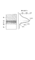
- FIG. 2 is a schematic diagram of a vertical section of a sintered layer (filled layer after ignition).
- This sintered layer is divided into a plurality of zones according to the progress of the sintering reaction.
- the sintered layer has a temperature distribution as shown in FIG. 2, and the combustion reaction of the solid fuel proceeds sequentially from the upper layer to the lower layer.
- the sintered layer at an arbitrary time, in order from the bottom is a raw material zone (raw material zone) 9a, a drying zone (drying zone) 9b, a calcining zone (calcining zone) 9c, a combustion zone (combustion zone) 9d, and a cooling.
- the band (cooling zone) 9e is laminated. The characteristics of each zone are as follows.
- the raw material zone 9a is a zone corresponding to a temperature range of less than 100 ° C.
- the blended raw material (sintered raw material) charged in the sintering machine is in a wet state.
- the drying zone 9b is a zone corresponding to a temperature range of 100 ° C. or higher and lower than 300 ° C. In this drying zone 9b, the drying of the blended raw material proceeds actively.
- the calcination zone 9c is a zone corresponding to a temperature range of 300 ° C. or higher and lower than 700 ° C. In the calcining zone 9c, reactions such as decomposition of crystal water in iron ore and decarboxylation of limestone occur.
- the combustion zone 9d is a zone corresponding to a temperature range of 700 ° C. or higher and lower than 1300 ° C.
- the solid fuel reacts with oxygen in the suction air and burns, and the melting reaction and liquid phase sintering of iron ore and auxiliary materials proceed simultaneously.
- the cooling zone 9e is a zone corresponding to a temperature range from 1300 ° C. to room temperature. In this cooling zone 9e, a series of sintering reactions are completed, and the produced sintered body (sinter cake) is cooled.
- the present inventors are effective in improving the combustibility of the solid fuel by using the steam generated by the thermal decomposition of the crystal water in the iron ore. I found it useful.
- the present inventors As a result of conducting a sintering test using a raw material (sintering raw material) obtained by mixing a combustion solid fuel having a low combustion start temperature and a high crystalline hydrous ore, the present inventors It was discovered that pyrolysis reaction and combustion of the low temperature combustion solid fuel occur simultaneously in the calcining zone 9c, and water vapor can be effectively supplied to the combustion atmosphere of the solid fuel. Furthermore, the present inventors use a combustion solid fuel having a low combustion start temperature (low temperature combustion solid fuel), thereby promoting the reaction between H 2 O and C, improving productivity, and in the exhaust gas by combustion. It was confirmed that the NOx of NO was reduced.
- a combustion solid fuel having a low combustion start temperature low temperature combustion solid fuel
- the present invention has been made on the basis of the above findings, and has adopted the following means.
- a sintering raw material an iron ore containing a high crystalline hydrous ore containing 4.0 mass% or more of crystal water, an auxiliary raw material, and a combustion reaction start temperature
- the surface layer of the sintered raw material is ignited; air is sucked from the upper side to the lower side of the sintered raw material.
- the said low-temperature combustion solid fuel carbonizes either subbituminous coal, lignite, or the mixed coal which mixed the said subbituminous coal and the said lignite. Char obtained in this way may be used.
- sintering is performed such that steam is supplied to the combustion reaction of solid fuel without using conventional watering and steam addition.
- Raw materials can be provided.
- this sintering raw material the productivity of sintered ore can be improved and NOx in exhaust gas can be reduced.
- a low-temperature combustion solid fuel having a combustion start temperature of less than 450 ° C. is used as the solid fuel to be blended with the sintering raw material.
- char (charcoal material) obtained by dry distillation of sub-bituminous coal, lignite, or mixed coal obtained by mixing sub-bituminous coal and lignite at a relatively low temperature of about 800 ° C
- These chars start to burn in a low temperature range of 330 to 450 ° C. and reach a maximum combustion state (maximum weight loss temperature) in a temperature range of 530 to 550 ° C.
- These chars having a low combustion temperature can be sufficiently combusted in the calcining zone 9c.
- the calcining zone 9c can enjoy the effect of supplying water vapor generated from the crystal water in the iron ore.
- the normal powder coke is a powdery coke produced by pulverizing a powdery coke or coke generated in a process for producing a blast furnace coke and a conveyance process to the blast furnace. Moreover, caking coal and non-slightly caking coal are used as coking coal.
- Table 1 the combustion performance of the low-temperature combustion solid fuel and the conventional solid fuel is shown in Table 1.
- the combustion start temperature and the maximum weight reduction temperature in Table 1 were measured using a differential thermal analyzer.
- the solid fuel used in the method for producing a sintered ore of the present invention may include only a low-temperature combustion solid fuel. Further, the solid fuel may include a low-temperature combustion solid fuel and a solid fuel other than the low-temperature combustion solid fuel (for example, pulverized coke, anthracite, and carbon-containing dust).
- the low-temperature combustion solid fuel may be char (low-temperature combustion char) obtained by dry distillation of subbituminous coal, lignite, or mixed coal obtained by mixing subbituminous coal and lignite. When only this low-temperature combustion char is used as the solid fuel, the combustion effect of the solid fuel can be maximized.
- the entire amount of char obtained by carbonizing subbituminous coal at 800 ° C. is used as the solid fuel.
- the combustion start temperature of char (subbituminous coal dry distillation char) obtained by dry distillation of subbituminous coal at 800 ° C is 330 ° C, and the maximum weight reduction temperature is 530 ° C. Therefore, the char obtained from subbituminous coal can be burned at a lower temperature among the low-temperature combustion solid fuels.
- char sub-bituminous coal high-temperature dry distillation char
- the combustion start temperature of a subbituminous coal high temperature dry distillation char dry distilled at 1100 ° C. is 540 ° C. Therefore, when the subbituminous coal high temperature dry distillation char is used, the combustibility of the solid fuel cannot be improved. Therefore, even when subbituminous coal is used, it is preferable to use char that has been carbonized at 1000 ° C. or lower.
- the carbonaceous material-containing powder generated inside or outside the coke process or the ironworks can be used as the solid fuel.
- the blending ratio of the low-temperature combustion solid fuel in the entire solid fuel must be 10 mass% or more. By including 10 mass% or more of the low temperature combustion solid fuel, the combustibility of the solid fuel can be sufficiently improved.
- high crystalline hydrous ores containing 4.0 mass% or more of crystal water pisolite ores containing 7 to 9 mass% of crystal water, 4 to 8 mass% of maramamba ores and 4 to 6 mass% of crystals It is preferable to use a Brockman ore containing water.
- Each of these high crystalline hydrous ores contains a mineral phase of iron hydroxide.
- iron carbonate and goethite-containing scales containing 4.0 mass% or more of crystal water can be used as raw materials for sintered ore.
- a plurality of high crystal hydrous ores may be mixed and used.
- a pisolite ore having a crystallization water content of 8.0 mass% or more for example, Yandi Kujina in Table 2.
- This pisolite ore (Yandy Kujina) currently has the largest crystallization water content of iron ore on the market.
- the upper limit of the content of crystallization water in the high crystalline hydrous ore is not particularly limited. However, since the crystal water is water combined with the compound in the iron ore, the content of crystal water in the high crystal water iron ore does not include 100 mass%.
- the blending ratio of the high crystalline hydrous ore needs to be 30 mass% or more in the entire sintered raw material.
- the blending ratio of the high crystalline hydrous ore in the sintered raw material is less than 30 mass%, a sufficient amount of water vapor cannot be supplied to the calcining zone 9c. That is, the water vapor generated by the decomposition of the crystal water is sequentially accompanied by the suction gas and discharged as exhaust gas. For this reason, when the amount of water vapor generated is small, the water vapor concentration in the calcining zone 9c decreases.
- the blending ratio of the high crystalline hydrous ore in the sintering raw material needs to be 30 mass% or more.
- the blending ratio of the high crystalline hydrous ore in the sintered raw material is preferably 80 mass% or less.
- pisolite ore having a crystallization water content of 8.0 mass% or more is contained in the total sintered raw material by 35 mass% or more and 45 mass% or less.
- a sufficient amount of water vapor can be secured in the calcining zone 9c of the sintered layer.
- water vapor is continuously supplied from the high crystalline hydrous iron ore by the heat supplied from the low-temperature combustion solid fuel. By supplying this water vapor, the water gas reaction (reaction between water vapor and carbon) and the water gas shift reaction (reaction between water vapor and carbon monoxide) are promoted, and hydrogen is supplied.
- the heat transfer speed in the calcining zone 9c is improved, and the productivity of the sintered ore is increased.
- hydrogen can reduce NOx and suppress the amount of NOx generated.
- the combustion efficiency of the solid fuel is improved by the water gas shift reaction.
- the productivity (sintering rate) of the sintered ore is increased, it is not necessary to consider the generation of an excessive melt.
- the present inventors have confirmed that a sintered ore can be produced without using an excessive melt by using a low-temperature combustion solid fuel and a high crystalline hydrous ore.
- the iron ore containing a high crystal water ore containing 4.0 mass% or more of crystal water, the auxiliary material, and the start temperature of the combustion reaction are A solid fuel containing 10 mass% or more of a low-temperature combustion solid fuel having a temperature of less than 450 ° C. is blended so as to contain 30 mass% or more of high crystalline hydrous ore and used as a sintering raw material.
- This sintered raw material is charged into a Dwytroid type sintering machine, and the surface layer portion of the sintered raw material is ignited.
- Air is sucked from above (cooling zone 9e) to below (raw material zone 9a) the sintered layer (sintered raw material) in the sintering machine. By this air suction, the sintering reaction proceeds continuously, and sintered ore is produced.
- the combustibility of the solid fuel can be greatly improved, and the productivity of the sintered ore can be improved. Further, the NOx concentration in the exhaust gas can be greatly reduced.
- a sintered ore was experimentally produced from a predetermined blending raw material (sintering raw material). After this blended raw material was charged to a height of 60 cm in the sintering test apparatus, a solid fuel on the surface of the packed bed was irradiated with a propane gas burner for 90 seconds and ignited. Thereafter, a sintering reaction was performed while suctioning air downward at a constant negative pressure of 15 kPa.
- the sintered body in which a series of sintering reactions were completed was sufficiently cooled, dropped from a height of 2 m four times and crushed, and a sintered ore having a particle size of 5 mm or more was recovered.
- the production rate and yield of the sintered ore were calculated from the material balance of the sintered ore and the blended raw material.
- the frame front speed (FFS) indicating the sintering speed was also calculated.
- the oxygen concentration and NOx concentration in exhaust gas were measured.
- Tables 2 and 3 show the blending conditions of the sintered raw materials and the test results of the sintered raw materials, respectively.
- Each solid fuel in Table 2 corresponds to each solid fuel in Table 1.
- the iron ore containing a high crystal hydrous ore containing 4.0 mass% or more of crystallization water, and the start temperature of the combustion reaction is less than 450 ° C.
- a solid fuel containing 10 mass% or more of low-temperature solid fuel (for example, char in Table 2) was used.
- the iron ore was blended so that the blending raw materials (sintering raw materials) of Examples 1 to 5 contained 30% by mass or more of high crystal hydrous ore. Therefore, as shown in Table 3, the sintering rate (FFS) was improved without lowering the yield of sintered ore products, and the production rate was significantly increased.
- the combustibility of the solid fuel was also greatly improved, and the oxygen concentration (excess air ratio) in the exhaust gas and the NOx generation amount were reduced.
- the low temperature combustion solid fuel was not used for the blended raw materials of Comparative Examples 1, 2, and 6.
- the blended raw material of Comparative Example 3 no high crystalline hydrous ore was used.
- high crystal hydrous ore was not blended by 30 mass% or more.
- the solid fuel of the blended raw material of Comparative Example 5 10 mass% or more of the low temperature combustion solid fuel was not blended.
- sub-bituminous coal high temperature dry distillation char having a high combustion start temperature was blended as a solid fuel.
- the production rate and FFS decreased, the combustibility of the solid fuel decreased, and the oxygen concentration (excess air ratio) in the exhaust gas and the NOx generation amount increased.
Landscapes
- Engineering & Computer Science (AREA)
- Chemical & Material Sciences (AREA)
- Manufacturing & Machinery (AREA)
- Geochemistry & Mineralogy (AREA)
- Geology (AREA)
- General Life Sciences & Earth Sciences (AREA)
- Life Sciences & Earth Sciences (AREA)
- Environmental & Geological Engineering (AREA)
- Materials Engineering (AREA)
- Mechanical Engineering (AREA)
- Metallurgy (AREA)
- Organic Chemistry (AREA)
- Manufacture And Refinement Of Metals (AREA)
- Solid Fuels And Fuel-Associated Substances (AREA)
Abstract
Description
本願は、2009年3月16日に、日本に出願された特願2009-063466号に基づき優先権を主張し、その内容をここに援用する。
(1)本発明の焼結鉱の製造方法では、焼結原料として、4.0mass%以上の結晶水を含有する高結晶水鉄鉱石を含む鉄鉱石と、副原料と、燃焼反応の開始温度が450℃未満である低温燃焼固体燃料を10mass%以上含む固体燃料とを前記高結晶水鉄鉱石が前記焼結原料中に30mass%以上含まれるように配合し;前記焼結原料をドワイトロイド式の焼結機に装入し;前記焼結原料の表層部に着火し;前記焼結原料の上方から下方へ向けて空気を吸引する。
(2)上記(1)に記載の焼結鉱の製造方法では、前記低温燃焼固体燃料は、亜瀝青炭、褐炭、または、前記亜瀝青炭と前記褐炭とを混合した混合炭のいずれかを乾留して得られたチャーであってもよい。

焼結原料の配合条件および焼結原料の試験結果を表2および表3にそれぞれ示す。なお、表2中の各固体燃料は、表1中の各固体燃料にそれぞれ対応している。


1a 鉄鉱石
2 石灰石ホッパー
2a 石灰石
3 コークスホッパー
3a コークス
4 返鉱ホッパー
4a 返鉱
5 造粒機
6 焼結原料
7 サージホッパー
8 ドラムフィーダー
8a シュート
9 充填層(焼結層)
9a 原料帯(原料ゾーン)
9b 乾燥帯(乾燥ゾーン)
9c 仮焼帯(仮焼ゾーン)
9d 燃焼帯(燃焼ゾーン)
9e 冷却帯(冷却ゾーン)
10 点火炉
11 焼結ケーキ
12 排鉱部
20 排風機
30 焼結機
46 床敷用焼結鉱
Claims (2)
- 焼結原料として、4.0mass%以上の結晶水を含有する高結晶水鉄鉱石を含む鉄鉱石と、副原料と、燃焼反応の開始温度が450℃未満である低温燃焼固体燃料を10mass%以上含む固体燃料とを前記高結晶水鉄鉱石が前記焼結原料中に30mass%以上含まれるように配合し;
前記焼結原料をドワイトロイド式の焼結機に装入し;
前記焼結原料の表層部に着火し;
前記焼結原料の上方から下方へ向けて空気を吸引する;
ことを特徴とする焼結鉱の製造方法。 - 前記低温燃焼固体燃料は、亜瀝青炭、褐炭、または、前記亜瀝青炭と前記褐炭とを混合した混合炭のいずれかを乾留して得られたチャーであることを特徴とする請求項1に記載の焼結鉱の製造方法。
Priority Applications (4)
| Application Number | Priority Date | Filing Date | Title |
|---|---|---|---|
| KR1020117021125A KR101409516B1 (ko) | 2009-03-16 | 2010-03-08 | 소결광의 제조 방법 |
| JP2011504734A JP4837799B2 (ja) | 2009-03-16 | 2010-03-08 | 焼結鉱の製造方法 |
| CN2010800117053A CN102348816B (zh) | 2009-03-16 | 2010-03-08 | 烧结矿的制造方法 |
| BRPI1012529-9A BRPI1012529B1 (pt) | 2009-03-16 | 2010-03-08 | Método para produção de sínter |
Applications Claiming Priority (2)
| Application Number | Priority Date | Filing Date | Title |
|---|---|---|---|
| JP2009063466 | 2009-03-16 | ||
| JP2009-063466 | 2009-03-16 |
Publications (1)
| Publication Number | Publication Date |
|---|---|
| WO2010106756A1 true WO2010106756A1 (ja) | 2010-09-23 |
Family
ID=42739424
Family Applications (1)
| Application Number | Title | Priority Date | Filing Date |
|---|---|---|---|
| PCT/JP2010/001600 Ceased WO2010106756A1 (ja) | 2009-03-16 | 2010-03-08 | 焼結鉱の製造方法 |
Country Status (5)
| Country | Link |
|---|---|
| JP (1) | JP4837799B2 (ja) |
| KR (1) | KR101409516B1 (ja) |
| CN (1) | CN102348816B (ja) |
| BR (1) | BRPI1012529B1 (ja) |
| WO (1) | WO2010106756A1 (ja) |
Cited By (5)
| Publication number | Priority date | Publication date | Assignee | Title |
|---|---|---|---|---|
| JP2021031749A (ja) * | 2019-08-28 | 2021-03-01 | 日本製鉄株式会社 | 焼結排ガスのNOx低減方法 |
| JPWO2024084749A1 (ja) * | 2022-10-18 | 2024-04-25 | ||
| WO2024116777A1 (ja) * | 2022-12-02 | 2024-06-06 | Jfeスチール株式会社 | 焼結鉱の製造方法 |
| WO2024116778A1 (ja) | 2022-12-02 | 2024-06-06 | Jfeスチール株式会社 | 焼結鉱の製造方法 |
| EP4628606A4 (en) * | 2022-11-29 | 2026-03-25 | Nippon Steel Corp | Sintered Ore Production Process |
Families Citing this family (6)
| Publication number | Priority date | Publication date | Assignee | Title |
|---|---|---|---|---|
| CN105274269B (zh) * | 2014-07-22 | 2017-07-28 | 宝山钢铁股份有限公司 | 一种烧结混合料的布料方法 |
| KR20210072807A (ko) * | 2018-12-07 | 2021-06-17 | 제이에프이 스틸 가부시키가이샤 | 소결광의 제조 방법 |
| CN111172385B (zh) * | 2020-01-20 | 2022-04-08 | 包头钢铁(集团)有限责任公司 | 一种利用高结晶水铁矿粉制备烧结矿的方法 |
| JP7534703B2 (ja) * | 2021-09-29 | 2024-08-15 | 日本製鉄株式会社 | 製鉄方法 |
| EP4578965A4 (en) | 2022-09-12 | 2025-12-17 | Jfe Steel Corp | CARBONATED MATERIAL FOR USE IN THE PRODUCTION OF SINTERED ORE |
| JPWO2025191948A1 (ja) * | 2024-03-12 | 2025-09-18 |
Citations (6)
| Publication number | Priority date | Publication date | Assignee | Title |
|---|---|---|---|---|
| JPH05230558A (ja) * | 1992-02-19 | 1993-09-07 | Nisshin Steel Co Ltd | 焼結鉱の製造方法 |
| JPH08246069A (ja) * | 1995-03-13 | 1996-09-24 | Kawasaki Steel Corp | 焼結鉱の製造方法 |
| JP2002371323A (ja) * | 2001-06-18 | 2002-12-26 | Nkk Corp | 通気性を改善した焼結鉱の製造方法及び装置 |
| JP2004027250A (ja) * | 2002-06-21 | 2004-01-29 | Sumitomo Metal Ind Ltd | 焼結鉱の製造方法 |
| JP2007191770A (ja) * | 2006-01-20 | 2007-08-02 | Kobe Steel Ltd | 焼結鉱の製造方法 |
| JP2009298909A (ja) * | 2008-06-12 | 2009-12-24 | Nippon Steel Engineering Co Ltd | 熱分解チャーの焼結用炭材としての利用方法 |
Family Cites Families (2)
| Publication number | Priority date | Publication date | Assignee | Title |
|---|---|---|---|---|
| KR0173842B1 (ko) * | 1994-09-21 | 1999-02-18 | 가타오카 겐지 | 고결정수 철광석을 원료로 사용하는 소결광의 제조방법 |
| TW440613B (en) * | 1996-01-11 | 2001-06-16 | Mitsubishi Material Silicon | Method for pulling single crystal |
-
2010
- 2010-03-08 JP JP2011504734A patent/JP4837799B2/ja active Active
- 2010-03-08 WO PCT/JP2010/001600 patent/WO2010106756A1/ja not_active Ceased
- 2010-03-08 CN CN2010800117053A patent/CN102348816B/zh active Active
- 2010-03-08 KR KR1020117021125A patent/KR101409516B1/ko active Active
- 2010-03-08 BR BRPI1012529-9A patent/BRPI1012529B1/pt active IP Right Grant
Patent Citations (6)
| Publication number | Priority date | Publication date | Assignee | Title |
|---|---|---|---|---|
| JPH05230558A (ja) * | 1992-02-19 | 1993-09-07 | Nisshin Steel Co Ltd | 焼結鉱の製造方法 |
| JPH08246069A (ja) * | 1995-03-13 | 1996-09-24 | Kawasaki Steel Corp | 焼結鉱の製造方法 |
| JP2002371323A (ja) * | 2001-06-18 | 2002-12-26 | Nkk Corp | 通気性を改善した焼結鉱の製造方法及び装置 |
| JP2004027250A (ja) * | 2002-06-21 | 2004-01-29 | Sumitomo Metal Ind Ltd | 焼結鉱の製造方法 |
| JP2007191770A (ja) * | 2006-01-20 | 2007-08-02 | Kobe Steel Ltd | 焼結鉱の製造方法 |
| JP2009298909A (ja) * | 2008-06-12 | 2009-12-24 | Nippon Steel Engineering Co Ltd | 熱分解チャーの焼結用炭材としての利用方法 |
Cited By (11)
| Publication number | Priority date | Publication date | Assignee | Title |
|---|---|---|---|---|
| JP2021031749A (ja) * | 2019-08-28 | 2021-03-01 | 日本製鉄株式会社 | 焼結排ガスのNOx低減方法 |
| JP7265162B2 (ja) | 2019-08-28 | 2023-04-26 | 日本製鉄株式会社 | 焼結排ガスのNOx低減方法 |
| JPWO2024084749A1 (ja) * | 2022-10-18 | 2024-04-25 | ||
| JP7782667B2 (ja) | 2022-10-18 | 2025-12-09 | Jfeスチール株式会社 | 焼結鉱の製造方法 |
| EP4628606A4 (en) * | 2022-11-29 | 2026-03-25 | Nippon Steel Corp | Sintered Ore Production Process |
| WO2024116777A1 (ja) * | 2022-12-02 | 2024-06-06 | Jfeスチール株式会社 | 焼結鉱の製造方法 |
| JPWO2024116777A1 (ja) * | 2022-12-02 | 2024-06-06 | ||
| WO2024116778A1 (ja) | 2022-12-02 | 2024-06-06 | Jfeスチール株式会社 | 焼結鉱の製造方法 |
| KR20250114078A (ko) | 2022-12-02 | 2025-07-28 | 제이에프이 스틸 가부시키가이샤 | 소결광의 제조 방법 |
| KR20250116087A (ko) | 2022-12-02 | 2025-07-31 | 제이에프이 스틸 가부시키가이샤 | 소결광의 제조 방법 |
| JP7816506B2 (ja) | 2022-12-02 | 2026-02-18 | Jfeスチール株式会社 | 焼結鉱の製造方法 |
Also Published As
| Publication number | Publication date |
|---|---|
| JPWO2010106756A1 (ja) | 2012-09-20 |
| CN102348816A (zh) | 2012-02-08 |
| KR101409516B1 (ko) | 2014-06-19 |
| CN102348816B (zh) | 2013-06-19 |
| BRPI1012529A2 (pt) | 2016-03-29 |
| BRPI1012529B1 (pt) | 2018-01-23 |
| JP4837799B2 (ja) | 2011-12-14 |
| KR20110115609A (ko) | 2011-10-21 |
Similar Documents
| Publication | Publication Date | Title |
|---|---|---|
| JP4837799B2 (ja) | 焼結鉱の製造方法 | |
| JP5786795B2 (ja) | アブラ椰子核殻炭による焼結鉱製造方法 | |
| CN102010728A (zh) | 一种由煤热解制取半焦、焦油和煤气的方法 | |
| CN103234215A (zh) | 一种共混煤粉燃烧控制装置及其方法 | |
| CN102300965B (zh) | 铁矿石烧结用炭材 | |
| JP5403027B2 (ja) | 木質バイオマスを原料とした高炉操業方法およびコークスの製造方法 | |
| JP2020186436A (ja) | 焼結鉱の製造方法 | |
| JP5929489B2 (ja) | アブラ椰子核殻炭の製造方法 | |
| JP4842410B2 (ja) | 焼結用固体燃料の製造方法、焼結用固体燃料およびこれを用いた焼結鉱の製造方法 | |
| CN217636810U (zh) | 一种提高烧结成品率的烧结机 | |
| JP5862515B2 (ja) | アブラ椰子核殻炭による高炉操業方法 | |
| JPH05230558A (ja) | 焼結鉱の製造方法 | |
| CN108865316A (zh) | 应用于铁矿烧结的生物质燃料的制备方法 | |
| CN201648243U (zh) | 菱镁矿轻烧系统 | |
| JP5929491B2 (ja) | アブラ椰子核殻の有効活用方法 | |
| CN112320775A (zh) | 窑外预热高温固结的回转窑法磷酸生产系统及生产方法 | |
| Boiko et al. | The organization of iron ore agglomerate and pellets production with reduced environmental impact | |
| JP7838716B1 (ja) | 焼結鉱の製造方法 | |
| TWI914644B (zh) | 燒結礦的製造方法 | |
| JP5434340B2 (ja) | 焼結鉱の製造方法 | |
| JP2018003081A (ja) | 焼結鉱製造用焼結原料の製造方法 | |
| WO2025197206A1 (ja) | 焼結鉱の製造方法 | |
| JP5549143B2 (ja) | 焼結用原料の製造方法 | |
| KR101448083B1 (ko) | 용선 제조 설비 및 이를 이용한 용선 제조 방법 | |
| JP2025085248A (ja) | 焼結鉱の製造方法 |
Legal Events
| Date | Code | Title | Description |
|---|---|---|---|
| WWE | Wipo information: entry into national phase |
Ref document number: 201080011705.3 Country of ref document: CN |
|
| 121 | Ep: the epo has been informed by wipo that ep was designated in this application |
Ref document number: 10753253 Country of ref document: EP Kind code of ref document: A1 |
|
| ENP | Entry into the national phase |
Ref document number: 2011504734 Country of ref document: JP Kind code of ref document: A |
|
| ENP | Entry into the national phase |
Ref document number: 20117021125 Country of ref document: KR Kind code of ref document: A |
|
| NENP | Non-entry into the national phase |
Ref country code: DE |
|
| 122 | Ep: pct application non-entry in european phase |
Ref document number: 10753253 Country of ref document: EP Kind code of ref document: A1 |
|
| REG | Reference to national code |
Ref country code: BR Ref legal event code: B01A Ref document number: PI1012529 Country of ref document: BR |
|
| ENP | Entry into the national phase |
Ref document number: PI1012529 Country of ref document: BR Kind code of ref document: A2 Effective date: 20110913 |