WO2010103980A1 - 移動体の駆動装置 - Google Patents
移動体の駆動装置 Download PDFInfo
- Publication number
- WO2010103980A1 WO2010103980A1 PCT/JP2010/053461 JP2010053461W WO2010103980A1 WO 2010103980 A1 WO2010103980 A1 WO 2010103980A1 JP 2010053461 W JP2010053461 W JP 2010053461W WO 2010103980 A1 WO2010103980 A1 WO 2010103980A1
- Authority
- WO
- WIPO (PCT)
- Prior art keywords
- gear
- base
- rack
- moving body
- movable body
- Prior art date
- Legal status (The legal status is an assumption and is not a legal conclusion. Google has not performed a legal analysis and makes no representation as to the accuracy of the status listed.)
- Ceased
Links
Images


Classifications
-
- B—PERFORMING OPERATIONS; TRANSPORTING
- B60—VEHICLES IN GENERAL
- B60N—SEATS SPECIALLY ADAPTED FOR VEHICLES; VEHICLE PASSENGER ACCOMMODATION NOT OTHERWISE PROVIDED FOR
- B60N3/00—Arrangements or adaptations of other passenger fittings, not otherwise provided for
- B60N3/10—Arrangements or adaptations of other passenger fittings, not otherwise provided for of receptacles for food or beverages, e.g. refrigerated
- B60N3/102—Arrangements or adaptations of other passenger fittings, not otherwise provided for of receptacles for food or beverages, e.g. refrigerated storable or foldable in a non-use position
-
- B—PERFORMING OPERATIONS; TRANSPORTING
- B60—VEHICLES IN GENERAL
- B60N—SEATS SPECIALLY ADAPTED FOR VEHICLES; VEHICLE PASSENGER ACCOMMODATION NOT OTHERWISE PROVIDED FOR
- B60N3/00—Arrangements or adaptations of other passenger fittings, not otherwise provided for
- B60N3/10—Arrangements or adaptations of other passenger fittings, not otherwise provided for of receptacles for food or beverages, e.g. refrigerated
- B60N3/105—Arrangements or adaptations of other passenger fittings, not otherwise provided for of receptacles for food or beverages, e.g. refrigerated for receptables of different size or shape
- B60N3/106—Arrangements or adaptations of other passenger fittings, not otherwise provided for of receptacles for food or beverages, e.g. refrigerated for receptables of different size or shape with adjustable clamping mechanisms
-
- B—PERFORMING OPERATIONS; TRANSPORTING
- B60—VEHICLES IN GENERAL
- B60R—VEHICLES, VEHICLE FITTINGS, OR VEHICLE PARTS, NOT OTHERWISE PROVIDED FOR
- B60R7/00—Stowing or holding appliances inside vehicle primarily intended for personal property smaller than suit-cases, e.g. travelling articles, or maps
- B60R7/04—Stowing or holding appliances inside vehicle primarily intended for personal property smaller than suit-cases, e.g. travelling articles, or maps in driver or passenger space, e.g. using racks
- B60R7/06—Stowing or holding appliances inside vehicle primarily intended for personal property smaller than suit-cases, e.g. travelling articles, or maps in driver or passenger space, e.g. using racks mounted on or below dashboards
Definitions
- the present invention relates to a drive device that moves a moving body with respect to a base via meshing of a rack and a gear, and in particular, has a biasing means interposed between the moving body and a gear, and the gear rotates in one direction.
- the present invention relates to a driving device for a moving body configured to accumulate a biasing force for movement in a biasing means in the process of doing so.
- the target drive device is disclosed in Patent Documents 1 and 2 for the purpose of improving the movement characteristics and usability in the specification of moving the moving body between the first position and the second position on the base side.
- the movable body moves through the meshing between the rack and the gear, and has an urging means interposed between the gear and accumulates the urging force in the urging means in the process of rotating the gear in one direction,
- the gear rotates in the other direction by the accumulated urging force and moves the moving body to one of the first position and the second position.
- the gear is linked with the urging means, for example, when an arrangement error or assembling error of the gear with respect to the moving body occurs, the urging force accumulation degree of the urging means changes for each product, and the moving body is attached.
- the pushing operation force against the force (that is, the urging force accumulation process) and the moving speed of the moving body moved by the urging force are factors.
- Patent Document 1 has a biasing force changing unit that changes the biasing force of the biasing unit by an operator's operation, and has a structure that can adjust the variation of the biasing force for each product by the biasing force changing unit. Disclosure.
- This urging means has an end side fixing portion of the urging member and an operation portion for operating the position change of the fixing portion.
- the urging force changing means has a permissible portion that allows movement of the fixed portion, and a plurality of locking portions that are arranged within a moving range of the fixed portion and that can lock the fixed portion, and the fixed portion is locked. In this structure, the urging force of the urging means is changed according to the position of the engaging portion.
- Patent Document 2 is attached to a first stopper portion provided on the outer periphery of a gear (pinion) and a moving body (a base body composed of a holder body or the like), and at least a part of the moving region of the first stopper portion is disclosed. And a second stopper portion that moves between a locking position that protrudes to the outside and a release position that is entirely retracted out of the movement region.
- the second stopper portion when the second stopper portion is assembled to the base, the second stopper portion is disposed at the locking position and locked with the first stopper portion, and the moving body moves between the first position and the second position.
- the movable body can be assembled to the base with the urging means having an initial urging force so as to be arranged at the release position.
- the second stopper portion is attached to the moving body, a locking position where a part protrudes from the moving region of the first stopper portion, and a releasing position where the whole is pulled out of the moving region. Therefore, it is complicated and requires positional accuracy with respect to the first stopper portion on the gear side. Further, in this structure, since the second stopper portion is provided on a member to be rotated (the bottom support member in FIG. 2 or the connecting member in FIG. 6), the movable body is maintained while the stopper portions are engaged with each other. Is difficult to insert into the space of the base, and the engagement may be released by the insertion force, or the meshing position between the gear and the tooth portion of the rack may be shifted.
- the present invention solves the above problems.
- the purpose thereof is, for example, a structure in which the gear is supported by the moving body in a state where the urging means has an initial urging force in order to sufficiently exhibit the dynamic characteristics due to the urging force, and is further assembled to the base from that state.
- the positioning means of the present invention With the positioning means of the present invention, the meshing position between the gear and the tooth portion of the rack is maintained as designed, so that the operating characteristics can be obtained reliably and optimally.
- Another object is to easily realize the positioning means without increasing the number of members.
- a movable body is assembled to a base so as to be movable between a first position and a second position on the base side through meshing of a rack and a gear, and the gear Urging means interposed between the two, the urging force is accumulated in the urging means in the course of rotation of the gear in one direction, and the gear is rotated in the other direction by the accumulated urging force.
- the drive device that moves the moving body to one of the first position and the second position, when the moving body is assembled to the base, the gear and the rack are moved by moving the moving body along the base. It has the positioning means which meshes
- the above-mentioned present invention is more preferably embodied as follows. That is, (1) The moving body is taken in and out of the space of the base, and the positioning means is provided on the inner side of the partition wall partitioning the space, and the convex portion increases the amount of protrusion toward the inner side of the space. And a concave portion provided in the gear and engageable with the convex portion.
- the positioning means is provided on the inner side of the partition wall that partitions the base-side space, and the convex portion increases the amount of protrusion toward the back of the space. Since it consists of the recessed part provided in the gear, it can implement easily, without increasing the number of members compared with the structure of patent document 2, for example, and malfunction does not occur easily.
- the gear engages with the rack and simultaneously engages with the concave portion when the base portion partition wall passes through the convex portion with elastic displacement. Furthermore, the one part which divides the recessed part in the engagement state is latched to the end surface of the convex part, and the meshing state with the rack is maintained.
- the drive and the teeth of the gear and the rack are accompanied by a batching sound at the time of restoration after the elastic displacement of the base side partition wall. Since the portion is engaged with the predetermined portion, the assembling operability can be improved.
- the positioning means has a configuration in which the tooth portions of the gear and the rack are different from other tooth shapes and have engaging portions and engaged portions that can be engaged with each other. .
- the positioning means has an engaging portion and an engaged portion that are different from other tooth shapes and can be engaged with each other at the gear and rack tooth portions, for example, Compared to the structure, it can be easily implemented without increasing the number of members. Further, the drive device has an advantage that the engagement state between the engaging portion and the engaged portion can be visually confirmed as to whether or not the positioning is normally performed as compared with the positioning means.
- the movable body side fitting hole and the gear side claw portion are simple configurations. Therefore, compared with the structure of Patent Document 2, it is simplified and becomes easy to implement, and malfunction is unlikely to occur.
- the gear and the tooth portion of the rack are always meshed at a predetermined position by the positioning means by the normal moving operation of the moving body along the base.
- the driving device for the moving body supports the gear on the moving body in a state where the urging means has an initial urging force.
- the operating characteristics using the rack / gear engagement mechanism and the urging force can be reliably and optimally imparted.
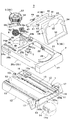
- (a) is an operation diagram showing a use position of the movable body, and (b) is a storage position of the movable body. It is the block diagram which decomposed
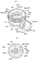
- (A) is a block diagram which shows the control means provided between the gear of FIG. 1 (a) (b) and a moving body,
- (b) is a schematic top view which shows the state which looked at the gear from the top. .
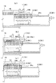
- (A) shows the posture when the moving body is assembled to the base as shown in FIG.
- FIG. 3 (a), (b) is an enlarged view of part A of (a), and (c) is an enlarged view of part B of (a).
- It is a block diagram. (A) to (c) show the movement process from the state of FIG. 4 (a) to the state of FIG. 3 (a) corresponding to the CC cross section of FIG. 4 (b).
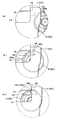
- (A) to (c) are schematic views showing a gear portion in each process corresponding to FIGS. 5 (a) to (c).
- the device structure, assembly, and operation will be described in detail in this order.
- the drive device 9 in the form of (device structure) includes a case 1 having a rack 14, a holder body 2 movably incorporated in the case 1, and a bottom pivotally supported in a frame 21 of the holder body 2.
- the support member 3, the gear 5 supported by the rear recess 25 of the holder body 2, the arm 4 operatively connecting the bottom support member 3 and the gear 5, and the gear 5 and the recess 25 are disposed.
- a biasing means 6 having a coil spring configuration, a push-push type latch means (a pin portion 7a of the swinging piece and a cam groove 16), and a rotary damper 8 are provided.
- the structural feature is that the holder main body 2 is assembled to the case 1 so as to be movable between a use position protruding from the case 1 through engagement of the rack 14 and the gear 5 and a storage position accommodated in the case 1. And a spring-type biasing means 6 interposed between the holder main body 2 and the gear 5, and the biasing force is accumulated in the biasing means 6 in the process of the gear 5 rotating in one direction,
- the base of the present invention is the case 1, the moving body of the present invention is the holder main body 2, the first position is the use position where the holder main body 2 protrudes from the case 1, and the second position is the holder main body 2. It is an example at the time of setting it as the storage position accommodated in case 1.
- the base and the moving body of the present invention are not limited to this form.
- the base of the present invention is a box body
- the moving body of the present invention is a lid
- the first position and the second position May be the closed position of the lid with the opening of the box body closed, or the open position of the lid with the opening of the box body opened.
- the base of the present invention may be a storage main body such as a desk that forms the storage portion
- the movable body of the present invention may be a drawer body that is taken in and out of the storage portion.
- the members constituting the drive device 9 are the configurations of the case 1, the holder body 2, the bottom support member 3, the arm 4, the gear 5, the latch means swing piece 7, and the rotary damper 8 except for the biasing means 6. Both members are made of resin, but other than resin may be used. Among these, as shown in FIG. 2, the case 1 has a rectangular flat shape in which the space is defined by the upper and lower walls 10, 11, both side walls 12, and the front end wall, and is open at the front, that is, the rear side.
- the upper wall 10 is located in the middle of the left and right, and has a wide opening 13 extending in the front-rear direction, a rack 14 provided continuously in the front-rear direction along one inner surface of the opening 13, and both sides 4 and a pair of narrow guide grooves 15 extending in the front-rear direction, positioning grooves 10b provided on the upper wall inner surface 10a side and communicating with the guide grooves 15 from the rear end, and FIG. As shown in c), it has a convex portion 19 that protrudes in front of the rack 14 and constitutes positioning means.
- the tooth portion of the rack 14 is formed into a differently shaped tooth 14a as shown in the enlarged view of FIG.
- This tooth 14a corresponds to the engaged portion constituting the positioning means of claim 4, and has a tooth shape that is two to three times thicker than other teeth.
- one guide groove 15 is provided with a rectangular window portion 15a on the front side, and the inside of the case is exposed from the window portion 15a.
- the convex portion 19 is located in front of the irregularly shaped teeth 14a of the rack 14, and has an inclined surface 19a that increases the amount of protrusion from the space entrance side toward the space back side.
- a heart-shaped cam groove 16 constituting a latch means is provided on the inner surface of the lower wall 11 immediately below the window portion 15a.
- the cam groove 16 locks the holder body 2, which will be described later, at the storage position of the holder body 2 via the pin portion 7 a of the swing piece 7.
- mounting fixing portions 17 are provided on the rear side.
- guide grooves 18 are extended in the front-rear direction in a state of facing each other.
- the holder main body 2 has a substantially rectangular frame shape corresponding to the space of the case 1, and is integrated with a front portion 20a that defines the inside 21 of the frame portion 20 and a front side of the front portion 20a. It consists of part 20b.
- the front portion 20a is sized so that the inside of the frame 21 can be inserted downward with a margin, and is integrated with the oblique bottom support member guide grooves 22 provided on the opposite inner surfaces on both sides and the rear end side.
- a sub-holder 28 provided in the left and right intermediate portion corresponding to the decorative plate 27 in the frame 21 and capable of swinging up and down and biased in a horizontal direction. Yes.
- the rear portion 20b is an arrangement portion for a functional member, and includes shaft holes 23 provided on the opposing inner surfaces on both sides, ribs 24a provided on the front sides of both sides, and ribs 24b provided on both sides of the upper surface.
- a pivot support portion (not shown) that is provided below one rib 24b and pivotally supports the swing piece 7, a large circular recess portion 25 provided slightly on one side from the left and right middle, and a bottom surface of the recess 25
- a damper mounting portion 25b penetrating a part of the periphery of the recess vertically, and a support shaft 26 protruding from the center of the recess 25.
- each rib 24a is fitted in the case side guide groove 18.
- the rib 24b is formed in a stepped portion 24c whose rear side (front side) is one step lower, and is formed in an inclined portion 24d that is inclined so that the front side becomes lower toward the front.
- the ribs 24b are fitted together by pushing the corresponding inclined portions 24d into the respective guide grooves 15, and guide the movement of the holder body 2 relative to the case 1 in the fitted state.
- the stepped portion 24c hits the corresponding end surface of the guide groove 15 when the holder main body 2 is moved in the protruding direction, and prevents the holder main body 2 from coming off from the case 1.
- the fitting hole 25 a is provided as a relatively large substantially rectangular opening on the front side of the recess 25.
- a claw portion 59 of the gear 5 described later is engaged with one end side of the hole as shown in FIG.
- a circular shallow groove 25d centered on the support shaft 26 is formed on the upper surface of the recess 25 from the other end side of the fitting hole 25a to the vicinity of one end side of the hole. Is provided. The claw portion 59 slides along the groove 25d from the fitting hole 25a when the gear 5 is rotated clockwise from the position shown in FIG. Through the engagement hole 25a.
- the urging means 6 and the gear 5 are arranged on a coaxial line with respect to the support shaft 26.
- the support shaft 26 protrudes from the center of the recess 25 as shown in FIG. 2 and FIG. 3B, and has a slit penetrating vertically.
- the corresponding end 6b is locked.
- the gear 5 is provided around a tooth portion 50 provided around the upper side of the periphery around the shaft hole 5 a and meshing with the rack 14, and a cylindrical portion 51 integrated below the tooth portion 50. And a claw portion 59 projecting downward from a side edge portion approaching the lower surface.
- the cam groove 56 is provided in the vertical direction around the cylindrical portion 51 and is divided by the inclined piece 51 b and the inclined piece 51 c, and the inclined groove 57 provided around the upper side of the cylindrical portion 51.
- a lower parallel groove 58 provided around the lower side of the cylindrical portion 51 and leading from the back side of the inclined piece 51c to the lower inlet of the inclined groove 57.
- the claw portion 59 is provided at the lower end of the inclined piece 51c and constitutes the regulating means of the present invention together with the fitting hole 25a described above.
- claw part 59 maintains the initial state which the gear 5 accumulate
- a ring portion 52a that defines the upper side of the shaft hole 5a, and a cylinder end surface that is integrated around the lower side of the ring portion 52a.
- the part 53, the recessed part 54 that is further lowered in front of the escape part 53, and the engaging part 54a that constitutes the escape part 53 of the tooth part 50 and that is notched one step lower in the tooth part are integrated. Is provided.
- the corresponding end 6a of the urging means 6 is locked in the locking hole 52e. That is, in this structure, the urging means 6 has, for example, the lower end portion 6b locked with the slit of the support shaft 6 and the upper end portion 6a locked with the locking hole 52e. From this state, the urging means 6 stores the initial urging force by rotating the gear 5 by a predetermined angle, and at the same time, the claw portion 59 engages with one end face of the fitting hole 25a to weaken the initial urging force. The rotation of the gear 5 is prevented.
- the restricting means of the present invention allows the rotation of the gear 5 in the direction in which the urging force is increased from the state in which the claw portion 59 is engaged with the one end face of the fitting hole 25a.
- the escape portion 53 is partitioned by a substantially L-shaped rib 55 and is a portion that comes into contact with the convex portion 19 on the case side when the holder body 2 is assembled to the case 1.
- the concave portion 54 is a portion that engages with the convex portion 19 on the case side.
- the engaging portion 54a constitutes the positioning means of claim 4 and engages with the irregularly shaped tooth 14a which is the engaged portion.
- the rib 55 includes an L-shaped vertical piece 55a and a horizontal piece 55b. The horizontal piece 55b also defines a part of the recess 54.
- the frame 21 of the holder main body it is pivotally supported by the guide grooves 22 on both sides and closes to the non-supporting position close to the holder main body and the holder main body.
- a bottom support member 3 that can be switched to a support position that is disposed, and an arm 4 that connects the bottom support member 3 and the gear 5 are provided.
- the arm 4 includes a support rod 40 disposed in the front width direction of the frame 21, a shaft portion 42 projecting from both ends of the support rod 40, and a pair of bending portions that are integrated on the left and right sides of the support rod 40 and bent upward.
- the arm portion 41 and the shaft portion 43 projecting from the upper outer surface of each arm portion 41, and the sliding contactor 44 protruding forward from a position slightly deviated from the center of the support rod 40 and the sliding contactor 44 upward And a protrusion 45 projecting from the head.
- the bottom support member 3 includes a substantially rectangular frame 30 having a size that fits inside the frame 21, and includes a bottom plate portion 31 that supports the bottom portion of the containers, and a side surface of the containers that faces the bottom plate portion 31. And a pair of shaft portions 34 and shaft holes 35 provided on the same axis on both sides.
- the rocking piece 7 has a tracing pin 7a that swivels along the shape of the cam groove 16, and is pivotally supported by a predetermined angle with respect to the holder body side pivoting portion.
- the swinging piece 7 constitutes a push-push locking mechanism that is a latch means together with the heart-shaped cam groove 16 and is locked when the holder body 2 is switched to the retracted position against the urging force. Then, the lock is released by the next pushing operation.
- the rotary damper 8 is, for example, a hydraulic type having a known rotary gear 8a, and the rotary gear 8a receives the resistance of the hydraulic oil in the main body 8b.
- the rotary damper 8 has an attachment piece 8c integrated with the main body 8b, and is attached to the attachment 25b by a pushing operation. This operation is performed when the rotary gear 8a is engaged with the gear tooth portion 50 and the holder body 2 is moved by the urging force of the urging means 6 to move from the retracted position to the use position. The vehicle is moved at a low speed by receiving the braking force.
- the above members are assembled in the following procedure example. That is, as a work procedure, the gear 5 and the biasing means 6, the swing piece 7 and the rotary damper 8 are assembled to the holder body 2 in the manner described above.
- the bottom support member 3 and the arm 4 are assembled to the holder main body 2 before and after this.
- the arm 4 is assembled to the holder body 2 so as to be rotatable by a predetermined angle by fitting each shaft portion 42 to the corresponding shaft hole 23 with respect to the holder body 2.
- the sliding contact 44 is fitted into the cam groove 56 (usually the inclined groove 57) of the gear 5.
- the arm 4 is in a state in which the arm portions 41 are arranged obliquely upward.
- the bottom support member 3 is fitted with the corresponding shaft portion 43 on the arm side in each shaft hole 35. .
- the bottom support member 3 is operatively connected to the arm 4 through the fitting of the shaft hole 35 and the shaft portion 43 while being pivotally supported by the holder body 2, and the sliding contact 44 is inclined. It becomes a support position which receives a container bottom face like FIG.1 (b) and FIG.4 (a) in the state fitted by the lower side of the groove
- FIG. The bottom support member 3 is the first stage in which the holder body 2 is pushed into the case 1 and switched from the use position in FIG. 1B to the storage position in FIG. 5, when it is slid to the vicinity of the entrance of the horizontal groove 58, it becomes a non-supporting position that becomes a substantially horizontal state inside the holder body 2 (inside the frame 21). Thereafter, the sliding contact 44 is slid along the horizontal groove 58 in accordance with the degree of insertion of the holder body 2 into the case 1.
- the holder body 2 is in a state in which the gear 5 incorporated in the rear portion 20b is almost in the case space by inserting the case 1 into the case from the state shown in FIGS. 4 (a) to 4 (c). More precisely, it is assembled and supported in the state of use in FIG. 5A to 5C and FIGS. 6A to 6C schematically show details at that time.
- Each figure (a) has shown the initial stage in which the holder main body 2 is pushed with respect to case 1 in the arrow direction. At this time, from the state where the holder body 2 matches the guide groove 18 with the ribs 24a on both sides of the case 1 and the corresponding positioning grooves 10b with the ribs 24a on both sides as shown in FIG.
- Push-in operation is performed. Then, when the holder body 2 is fitted into the guide groove 15 through the corresponding positioning groove 10b with the inclined portions 24d and ribs 24b on both sides, and the holder body 2 tries to move again in the protruding direction, each step portion 24c hits the corresponding end surface of the guide groove 15 to prevent the case 1 from coming off.
- the gear 5 supported by the holder main body 2 is engaged with the case-side rack 14, that is, at the use position of the holder main body 2 in FIG.
- the gear 5 of the holder body 2 is rotated by the rotation of the urging force of the gear 5.
- the moving speed through the engagement of the rack 14 changes, and the designed moving characteristics cannot be obtained.
- the present invention solves such a problem by the following operation.
- each figure (b) and each figure (c) have shown the intermediate state in which the holder main body 2 is assembled
- the convex part 19 becomes the inclined surface 19a which increases the amount of protrusion as it goes ahead like FIG.4 (c)
- the convex part 19 is elastically displaced by the partition wall part which forms this convex part.
- the vehicle runs on the gear side escape portion 43 relatively smoothly.
- the corresponding side surface of the convex portion 19 is pushed in the direction of the arrow in the figure while being positioned and guided along the vertical piece 55a in the rib 55 as shown in FIG. 6B.
- each of the above engagements is such that the partition wall portion (in this example, the upper wall 10 after forming the convex portion 19 or the left and right intermediate portions on the near side) is restored from the elastically displaced state to the original state. Done with a batching sound when played. For this reason, the operator confirms that the holder main body 2 is securely assembled to the case 1 by the patching sound and the engagement portion 54a and the teeth 14a as the engaged portions as shown in FIG. The engagement state can be confirmed by visual observation. Further, in this structure, the horizontal piece 55b of the ribs 55 that engage with the concave portion 54 and define the escape portion 53 in the engaged state at the same time as the gear 50 meshes with the rack 14. Lock to the end face of the convex portion 19. Thereby, in this structure, the meshing state of the gear 50 and the rack 14 is maintained, and the possibility that the gear 50 is inadvertently detached from the rack 14 is reliably eliminated.
- the partition wall portion in this example, the upper wall 10 after forming the conve
- the drive device 9 described above has a gear when the holder main body 1 is switched from the use position to the storage position in the storage position where the holder main body 2 is pushed into the case 1 as shown in FIG. 5 rotates clockwise while meshing with the rack 14, and an urging force proportional to the amount of rotation of the gear 5 is accumulated.
- the holder main body 2 is held at the storage position accommodated in the case 1 through the engagement of the latch means, that is, the pin portion 7a of the swing piece 7 and the heart-shaped cam groove 16 against the urging force.
- the sliding contactor 44 is fitted in the horizontal groove 58, and the protrusion 45 is in contact with a not-shown abutting portion provided on the inner surface of the upper wall of the rear portion 20b. Therefore, rattling is easily prevented although it is likely to occur between the members.
- the holder body 2 is switched to the use position, the decorative plate 27 of the holder body 2 is pushed. Then, the holder body 2 is disengaged from the pin portion 7 a and the cam groove 16, and the gear 5 is rotated counterclockwise by the biasing force accumulated in the biasing means 6 and meshes with the rack 14. 1 (b) is switched to the use position. In this switching process, the gear 5 is slowed down by the rotary damper 8 to alleviate rapid movement of the holder body 2. Further, the bottom support member 3 is switched from a non-support position to a support position that intersects the holder body 2 up and down by the cam action of the sliding contact 44 of the arm 4 and the cam groove 56 on the gear side.
- the sliding contactor 44 described above is fitted into the inclined groove 57 and is pressed against the left inclined piece 51b below the inclined groove 57, so that the rattling is surely generated between the members. Is prevented.
- the containers (not shown) are inserted downward into the holder body side frame 21 from above, the bottom of the containers is received by the bottom plate 31 on the bottom support member side, and the surroundings of the containers are The side support portion 32 and the sub-holder 28 are restrained and stably held.
- the above form does not restrict
- the present invention can be developed in various apparatuses with reference to this embodiment.
- the base and the holder main body are developed as a desk, an accessory case and a drawer thereof, various apparatus main bodies, a lid and a door thereof.
- the entire contents of the specification, claims, drawings and abstract of Japanese Patent Application No. 2009-0555580 filed on March 9, 2009 are cited here as disclosure of the specification of the present invention. Incorporated.
Landscapes
- Engineering & Computer Science (AREA)
- Mechanical Engineering (AREA)
- Physics & Mathematics (AREA)
- Thermal Sciences (AREA)
- Transportation (AREA)
- Transmission Devices (AREA)
- Vehicle Step Arrangements And Article Storage (AREA)
- Passenger Equipment (AREA)
Abstract
移動体がベースに対しラックとギアとの噛み合いを介してベース側第1位置と第2位置との間を移動可能に組み付けられ、かつギアとの間に介在された付勢手段を有し、ギアが一方向へ回転する過程で付勢手段に付勢力を蓄積し、ギアがその蓄積した付勢力により他方向へ回転して移動体を決められた一方へ移動する駆動装置において、移動体をベースに組み付ける際に、ベースに沿った移動体の移動操作によりギアとラックの歯部とを所定箇所で噛み合わせる位置決め手段を有している。
Description
本発明は、ベースに対し移動体をラックとギアとの噛み合いを介して移動する駆動装置に関し、特に移動体がギアとの間に介在された付勢手段を有し、ギアが一方向へ回転する過程で付勢手段に移動用の付勢力を蓄積する構成の移動体の駆動装置に関する。
対象の駆動装置は、移動体をベース側の第1位置と第2位置との間を移動する仕様において、移動特性と使い勝手を良好にする目的で特許文献1や2に開示されているごとく、移動体をラックとギアとの噛み合いを介して移動するとともに、ギアとの間に介在された付勢手段を有し、ギアが一方向へ回転する過程で付勢手段に付勢力を蓄積し、ギアがその蓄積した付勢力により他方向へ回転して移動体を第1位置及び第2位置の何れか一方へ移動する構造である。この構造では、ギアが付勢手段と連携されていることから、例えば移動体に対するギアの配置や組み付け誤差が生じると、製品ごとに付勢手段の付勢力蓄積度合いが変化し、移動体の付勢力に抗した(つまり付勢力蓄積過程での)押し操作力、付勢力で動かされる移動体の移動速度がばらつく要因となる。
ここで、特許文献1は、操作者の操作にて付勢手段の付勢力を変更する付勢力変更手段を有し、該付勢力変更手段により製品ごとの付勢力のばらつきを調整可能な構造を開示している。この付勢手段は、付勢部材の端部側固定部及び固定部の位置変更を操作する操作部とを有している。付勢力変更手段は、固定部の移動を許容する許容部と、固定部の移動範囲内に配設され固定部を係止可能にする複数の係止部とを有し、固定部が係止される係止部の位置に応じて付勢手段の付勢力を変更する構造である。
また、特許文献2は、ギア(ピニオン)の外周に設けられた第1ストッパ部と、移動体(ホルダ本体等からなるベース体)に取り付けられて、少なくとも一部が第1ストッパ部の移動領域に出っ張る係止位置と、全体が移動領域の外へ引っ込む解除位置との間を移動する第2ストッパ部とを有している。そして、この構造では、第2ストッパ部が移動体をベースに組み付ける際は係止位置に配されて第1ストッパ部と係止し、移動体が第1位置と第2位置との間を移動する際は解除位置に配されるようにして、付勢手段に初期付勢力を持たせた状態で移動体をベースに組み付け可能にしたものである。
上記特許文献1の付勢力変更構造では、設計上は付勢手段の配置部に制約され、製品化した後、操作部を摘んで位置変更すべく操作可能な配置部を確保できないことが多い。また、操作者つまり素人が手操作にて固定部の係止位置を変更することは煩わしいだけではなく、最適状態にセットできるとは限らない。
これに対し、特許文献2のストッパ構造では、第2ストッパ部が移動体に取り付けられて、一部が第1ストッパ部の移動領域に出っ張る係止位置と、全体が移動領域外へ引っ込む解除位置との間を移動する構成であるため複雑であり、ギア側の第1ストッパ部に対する位置精度も要求される。また、この構造では、第2ストッパ部が回動される部材(図2の底支持部材や図6の連結部材)に設けられるため、両ストッパ部が互いに係合した状態を維持して移動体をベースの空間に挿入操作し難く、挿入力によって前記係合が解除されたり、ギアとラックの歯部との噛み合い位置がずれることも起きる。
本発明は以上のような課題を解決するものである。その目的は、例えば、付勢力による動特性を充分発揮するため付勢手段に初期付勢力を持たせた状態でギアを移動体に支持し、更にその状態からベースに組み付ける構成であっても、本発明の位置決め手段によりギアとラックの歯部との噛み合い位置が設計通り維持され、それにより作動特性を確実かつ最適状態に得られるようにする。他の目的は、前記位置決め手段を部材数を増やすことなく簡易に実現することにある。
上記目的を達成するため本発明は、移動体がベースに対しラックとギアとの噛み合いを介して前記ベース側の第1位置と第2位置との間を移動可能に組み付けられ、かつ前記ギアとの間に介在された付勢手段を有し、前記ギアが一方向へ回転する過程で前記付勢手段に付勢力を蓄積し、前記ギアがその蓄積した付勢力により他方向へ回転して前記移動体を第1位置及び第2位置の何れか一方へ移動する駆動装置において、前記移動体を前記ベースに組み付ける際に、前記ベースに沿った前記移動体の移動操作により前記ギアと前記ラックの歯部とを所定箇所で噛み合わせる位置決め手段を有していることを特徴としている。
以上の本発明は、下記のごとく具体化されることがより好ましい。すなわち、(1)前記移動体は前記ベースの空間に出し入れされるとともに、前記位置決め手段は前記空間を区画している区画壁の内側に設けられて空間奥側に向かって突出量を増す凸部と前記ギアに設けられて前記凸部と係合可能な凹部とからなる構成である。
この場合、位置決め手段が図4(a)~(c)に例示されるごとくベース側空間を区画している区画壁の内側に設けられて空間奥側に向かって突出量を増す凸部と、ギアに設けられている凹部とからなるため、例えば特許文献2の構造に比べ部材数を増やすことなく簡単に実施でき、誤作動も起きにくい。
(2)前記ギアは、前記移動体が前記ベースの空間に挿入される初期過程で、前記区画壁側の弾性変位を伴って前記凸部を通過したときに前記ラックと噛み合うと同時に、前記凹部と前記凸部とが係合し、かつその係合状態で前記凹部を区画している片部を前記凸部の端面に係止して前記ラックとの噛み合い状態を維持可能となる構成である。
この場合、移動体をベース空間に挿入する初期過程で、ベース側区画壁の弾性変位を伴って凸部を通過したときにギアがラックと噛み合うと同時に凹部と凸部とが係合する。更にその係合状態で凹部を区画している片部を凸部の端面に係止してラックとの噛み合い状態を維持する。これにより、駆動装置としては、移動体がギアを支持した状態で、ベースの空間に挿入操作されると、ベース側区画壁の弾性変位後の復元時のバッチン音を伴ってギアとラックの歯部とが所定箇所で噛み合わせられるため、組み付け操作性を向上できる。
(3)前記位置決め手段は、前記ギアと前記ラックの歯部にそれぞれ他の歯形状とは異形で、かつ互いに係合可能な係合部と被係合部とを有している構成である。
この場合、位置決め手段がギアとラックの歯部にそれぞれ他の歯形状とは異形で、かつ互いに係合可能な係合部と被係合部とを有しているため、例えば特許文献2の構造に比べ部材数を増やすことなく簡単に実施できる。また、駆動装置としては、位置決め手段に比べて位置決めが正常になされているか否か、について係合部と被係合部との係合状態を目視して確認できる利点がある。
(4)前記ギアに設けられた爪部が前記移動体に設けられた嵌合穴に係合することにより、前記ギアが前記付勢手段に所定の付勢力を蓄積した初期状態を維持するとともに、前記付勢手段の初期状態より付勢力を弱める方向への回転を阻止する規制手段を有している構成である。
この場合、所定の付勢力を蓄えた付勢手段の初期状態より付勢力を弱める方向への回転を阻止する規制手段として、移動体側の嵌合穴とギア側の爪部という簡単な構成であるため、特許文献2の構造に比べて簡易化されて実施容易となり、誤作動も生じ難いものとなる。
本発明では、移動体がベースに沿った通常の移動操作によって、ギアとラックの歯部とが位置決め手段により常に所定箇所で噛み合わせられる。これにより、移動体の駆動装置としては、付勢手段に初期付勢力を持たせた状態でギアを移動体に支持し、更にその状態からベースに組み付ける構成でも、製品ごとの付勢力のばらつきをなくし、ラック/ギアによる噛み合い機構及び付勢力を利用した作動特性を確実かつ最適状態に付与できる。
以下、本発明の形態を図1(a)~図6(c)を参照しながら説明する。この説明では、装置構造、組立、作動の順に詳述する。
(装置構造)形態の駆動装置9は、ラック14を有しているケース1と、ケース1内に移動可能に組み込まれたホルダ本体2と、ホルダ本体2の枠内21に枢支された底支持部材3と、ホルダ本体2の後側凹部25に支持されたギア5と、底支持部材3とギア5とを作動連結しているアーム4と、ギア5と凹部25との間に配置された巻きばね構成の付勢手段6と、プッシュ・プッシュ式のラッチ手段(揺動片のピン部7aとカム溝16)と、回転ダンパ8とを備えている。構造特徴は、ホルダ本体2がケース1に対しラック14とギア5との噛み合いを介してケース1から突出した使用位置とケース1内に収容された収納位置との間を移動可能に組み付けられている構成と、ホルダ本体2とギア5との間に介在された巻きばねタイプの付勢手段6を有し、ギア5が一方向へ回転する過程で付勢手段6に付勢力を蓄積し、ギア5がその蓄積した付勢力により他方向へ回転してホルダ本体2を使用位置方向(又は収納位置方向)へ移動する構成と、ホルダ本体2をケース1に組み付ける際に、ケース1の空間に沿ったホルダ本体2の移動操作によりギア5とラック14の歯部とを所定箇所で噛み合わせる位置決め手段(54と19、又は、14aと54a)を有している構成とにある。
なお、この形態は、本発明のベースがケース1とし、本発明の移動体がホルダ本体2とし、第1位置がホルダ本体2をケース1から突出した使用位置、第2位置がホルダ本体2をケース1内に収容した収納位置とした場合の例である。但し、本発明のベース及び移動体は、この形態に限られず、例えば、特許文献1のごとく本発明のベースをボックス本体とし、本発明の移動体を蓋体とし、第1位置及び第2位置がボックス本体の開口を閉じた蓋体の閉位置、ボックス本体の開口を開放した蓋体の開位置としてもよい。また、本発明のベースを収納部を形成している机等の収納本体とし、本発明の移動体をその収納部に出し入れされる引出体としてもよい。
駆動装置9を構成している部材は、付勢手段6を除いて、ケース1、ホルダ本体2、底支持部材3、アーム4、ギア5、ラッチ手段用揺動片7及び回転ダンパ8の構成部材が共に樹脂製からなるが、樹脂以外でも差し支えない。このうち、ケース1は、図2に示されるごとく、空間が上下壁10,11、両側壁12、前端壁で区画された矩形扁平状からなり、手前つまり後側を開口している。上壁10は、左右中間に位置して前後に延設されている幅太の開口部13と、開口部13の片側内面に沿って前後方向に連続して設けられているラック14と、両側に位置して前後に延設されている幅細の1対のガイド溝15と、上壁内面10a側に設けられて後端から各ガイド溝15に通じている位置決め溝10b、及び図4(c)のごとくラック14の手前に突設されて位置決め手段を構成している凸部19とを有している。
ラック14の歯部は、後端側の歯形状を図2の拡大図に示すごとく異形状の歯14aに形成されている。この歯14aは、請求項4の位置決め手段を構成している被係合部に相当し、他の歯に比べて、2~3倍の厚い歯形状となっている。両ガイド溝15のうち、一方のガイド溝15には前側に矩形の窓部15aが設けられ、該窓部15aからケース内を露出している。凸部19は、ラック14の異形状の歯14aの手前に位置し、空間入口側から空間奥側に向かって突出量を増す傾斜面19aを有している。これに対し、下壁11の内面には、窓部15aの真下にラッチ手段を構成しているハート形のカム溝16が設けられている。このカム溝16は、後述するホルダ本体2を揺動片7のピン部7aを介してホルダ本体2の収納位置で係止する。両側壁12には取付用固定部17が後側に設けられている。両側壁12の内面には、ガイド溝18が対向した状態で前後方向に延設されている。
ホルダ本体2は、ケース1の空間に対応した概略矩形枠状となっていて、枠部20の枠内21を区画している前部分20aと、前部分20aの前側に一体化されている後部分20bとからなる。前部分20aは、枠内21が容器類を余裕を持って下向きに挿入可能な大きさで、両側の対向内面にそれぞれ設けられた斜めの底支持部材用ガイド溝22と、後端側に一体化された化粧板27と、枠内21内にあって化粧板27に対応した左右中間部に設けられて上下揺動可能かつ水平となる方向に付勢されているサブホルダ28とを有している。
後部分20bは、機能部材用配置部であり、両側の対向内面にそれぞれ設けられた軸穴23と、両側面の前側に設けられているリブ24aと、上面の両側に設けられているリブ24bと、一方のリブ24bの下側に設けられて揺動片7を枢支する不図示の枢支部と、左右中間より少し片側に設けられている大きな円状の凹部25と、凹部25の底面を貫通している嵌合穴25a及び凹部周囲の一部を上下に貫通しているダンパ用取付部25bと、凹部25の中心に突設された支持軸26とを有している。
このうち、各リブ24aはケース側ガイド溝18に嵌合する。リブ24bは、図4(a)のごとく後側(手前側)が一段低い段差部24cに形成され、前側が前方へ行くほど低くなるよう傾斜した傾斜部24dに形成されている。そして、リブ24bは、上記各ガイド溝15に対し対応する傾斜部24dを合わせて押し込むことで嵌合し、その嵌合状態でケース1に対するホルダ本体2の移動を案内する。また、段差部24cは、ホルダ本体2が突出方向へ移動されたとき、ガイド溝15の対応端面に当たってケース1に対するホルダ本体2の抜けを阻止する。これに対し、嵌合穴25aは、凹部25の手前側に比較的大きな略矩形状の開口として設けられている。この嵌合穴25aは、図3(a)のごとく後述するギア5の爪部59が穴一端側に係合する。なお、この例では、嵌合穴25aに関係して、凹部25の上面に支持軸26を中心とする円状の浅い溝25dが嵌合穴25aの穴他端側から穴一端側の近くまで設けられている。そして、爪部59は、ギア5が同図の位置から付勢力を蓄積する時計回りに回転されると、嵌合穴25aからその溝25dに沿って摺動し、約1回転すると、溝25dを弾性的に通過して嵌合穴25aと係合する。
凹部25には、付勢手段6及びギア5が支持軸26に対し同軸線上に枢支された状態で配置される。支持軸26は、図2及び図3(b)に示されるごとく凹部25の中心から突出されていると共に、上下に貫通したスリットを有し、該スリットに対し付勢手段6である巻きばねの対応端部6bを係止している。ギア5は、軸孔5aを軸心とした周囲のうち、上側周囲に設けられてラック14と噛み合う歯部50と、歯部50の下側に一体化した筒部51の周囲に設けられているカム溝56と、下面に接近した側縁部から下向きに突出されている爪部59とを有している。このうち、カム溝56は、筒部51の周囲上下方向に設けられて傾斜片51bと傾斜片51cとで区画されている傾斜溝57と、筒部51の上側周囲に設けられて傾斜溝57と連続している平行溝58と、筒部51の下側周囲に設けられて傾斜片51cの背面側より傾斜溝57の下側入口に通じている下側平行溝58とからなる。爪部59は、傾斜片51cの下端に設けられて上記した嵌合穴25aと共に本発明の規制手段を構成する。そして、爪部59は、嵌合穴25aの一端面に係合することにより、ギア5が付勢手段6に所定の付勢力を蓄積した初期状態を維持し、かつ付勢手段6の初期状態より付勢力を弱める方向への回転を阻止する。
また、ギア5の上端面側には、図3(a)(b)のごとく軸孔5aの上側を区画しているリング部52a、リング部52aの下側周囲に一体化されている筒端面部52bと、筒端面部52bの一部を上下に貫通している付勢手段用係止穴52eと、筒端面部52bと歯部50との間を一段低くしている窪み部52cと、筒端面部52bの外周と窪み部52cの歯部側内周とを繋いでいる複数の補強リブ52dと、係止穴52eと反対側に位置して歯部50の一部と共に少し低くした逃げ部53と、逃げ部53の手前を更に低くした凹部54と、歯部50のうち逃げ部53を構成し、かつ凹部54に接近した歯部分を一段低く切り欠いた係合部54aとが一体に設けられている。
このうち、係止穴52eには付勢手段6の対応端部6aが係止される。すなわち、この構造において、付勢手段6は、例えば、下端部6bが上記した支持軸6のスリットに対し係止され、上端部6aが係止穴52eに係止される。その状態から、付勢手段6はギア5が所定角回転されることで初期付勢力を蓄え、同時に、爪部59が嵌合穴25aの一端面に係合し該初期付勢力を弱める方向へのギア5の回転を阻止する。この本発明の規制手段は、爪部59が嵌合穴25aの一端面に係合した状態から、付勢力を増大する方向へのギア5の回転は許容する。
逃げ部53は、略L形リブ55により区画されており、ホルダ本体2がケース1に組み付けられる際に上記ケース側の凸部19と当接する部分である。凹部54は、上記ケース側の凸部19と係合する箇所である。係合部54aは請求項4の位置決め手段を構成し、上記被係合部である異形状の歯14aと係合する。リブ55はL形垂直片55a及び水平片55bからなる。水平片55bは凹部54の一部も区画している。
これに対し、ホルダ本体の枠内21には、両側のガイド溝22に枢支されてホルダ本体に近接する非支持位置と該ホルダ本体に対して垂下し、少なくとも一部が枠内の下方に配される支持位置とに切り換えられる底支持部材3と、底支持部材3とギア5とを連結するアーム4とが設けられている。
アーム4は、枠内21の前方幅方向に配置される支持杆40及び支持杆40の両端に突設された軸部42と、支持杆40の左右に一体化されて上方に屈曲する一対の腕部41及び各腕部41の上外面に突設された軸部43と、支持杆40の中央からやや偏った箇所から前方へ突出された摺接子44及び摺接子44の手前で上向きに突設された突起45とを備えている。一方、底支持部材3は、枠内21の内側に収まる大きさの概略矩形の枠体30からなり、容器類の底部を支持する底板部31と、底板部31と対向して容器類の側面を支持する側面支持部32と、両側に同軸線上に設けられている対の軸部34及び軸孔35とを有している。
また、上記揺動片7は、上記カム溝16の溝形状に沿って旋回するトレース用ピン7aを有し、ホルダ本体側枢支部に対し所定角だけ揺動可能に枢支される。そして、揺動片7は、上記したハート形のカム溝16とともにラッチ手段であるプッシュ・プッシュ係止機構を構成し、ホルダ本体2を付勢力に抗して格納位置に切り換えたときに係止し、次の押し操作により係止解除する。回転ダンパ8は、例えば、公知の回転ギア8aを有した油圧式であり、回転ギア8aが本体8b内の作動油の抵抗を受けている。また、回転ダンパ8は、本体8bに一体化された取付片部8cを有し、取付部25bに対し押し込み操作により装着される。この作動は、回転ギア8aが上記ギアの歯部50と噛み合っていて該噛み合いにより、ホルダ本体2が付勢手段6の付勢力で移動して格納位置より使用位置まで動くときに、回転ダンパ8の制動力を受けて低速移動されるようにする。
(組立)以上の各部材は次のような手順例にて組み付けられる。すなわち、作業手順としては、ホルダ本体2に対し上述した要領でギア5及び付勢手段6と、揺動片7及び回転ダンパ8とが組み付けられる。また、ホルダ本体2にはこれとは相前後して、底支持部材3及びアーム4が組み付けられる。この場合、アーム4は、ホルダ本体2に対し各軸部42を対応する軸孔23に嵌合することによりホルダ本体2に所定角だけ回動可能に組み付けられる。その際は、摺接子44がギア5のカム溝56(通常は傾斜溝57)に嵌合される。このため、アーム4は各腕部41を上斜めに配置した状態となる。底支持部材3は、例えば、各軸部35が枠内21の対応するガイド溝22に摺動可能に嵌合した後、各軸孔35に対しアーム側の対応する軸部43を嵌合する。
そして、底支持部材3は、ホルダ本体2に回動可能に枢支された状態で、アーム4に対し軸孔35及び軸部43の嵌合を介して作動連結され、摺接子44が傾斜溝5の下側に嵌合された状態で図1(b)及び図4(a)のごとく容器底面を受ける支持位置となる。また、底支持部材3は、ホルダ本体2がケース1内に押し込められて図1(b)の使用位置から同(a)の収納位置へ切り換えられる最初の段階、つまり摺接子44が傾斜溝5に沿って水平溝58の入口付近まで摺動されると、ホルダ本体2(枠内21)の内側に略水平状態となる非支持位置となる。以後はホルダ本体2のケース1内への挿入度合いに応じて摺接子44が水平溝58に沿って摺動される。
(作動)ホルダ本体2は、ケース1に対し図4(a)~(c)の状態からケース内への挿入操作により、後部分20bに組み込まれたギア5がほぼケース空間内に入った状態、正確には図1(b)の使用位置の状態に組み付け支持される。図5(a)~(c)と図6(a)~(c)はそのときの細部を模式的に示している。
(1)各図(a)は、ホルダ本体2がケース1に対し矢印方向に押されている初期段階を示している。このときは、ホルダ本体2がケース1に対し図4(b)のごとく両側のリブ24aを対応するガイド溝18に一致し、かつ両側の傾斜部24dを対応する位置決め溝10bに一致した状態から押し込み操作される。すると、ホルダ本体2は、両側の傾斜部24d及びリブ24bが対応する位置決め溝10bからガイド溝15に入って嵌合し、かつ、ホルダ本体2を再び突出方向へ移動しようとするとき各段差部24cがガイド溝15の対応端面に当たってケース1に対する抜けが阻止される。
(1)各図(a)は、ホルダ本体2がケース1に対し矢印方向に押されている初期段階を示している。このときは、ホルダ本体2がケース1に対し図4(b)のごとく両側のリブ24aを対応するガイド溝18に一致し、かつ両側の傾斜部24dを対応する位置決め溝10bに一致した状態から押し込み操作される。すると、ホルダ本体2は、両側の傾斜部24d及びリブ24bが対応する位置決め溝10bからガイド溝15に入って嵌合し、かつ、ホルダ本体2を再び突出方向へ移動しようとするとき各段差部24cがガイド溝15の対応端面に当たってケース1に対する抜けが阻止される。
ところで、以上のホルダ本体2の組み付け操作では、ホルダ本体2に支持されているギヤ5がケース側ラック14に対して互いに噛み合う歯部、つまり図1(b)のホルダ本体2の使用位置において、ギア5の初期状態(ギヤ5の歯部50のうち、ラック14の第1の歯14aと噛み合う箇所)が製品毎に変わると、ギア5の付勢力による回転、それに伴うホルダ本体2のギア5及びラック14の噛み合いを介した移動速度が変化し、設計通りの移動特性が得られないことになる。本発明はそのような不具合を次のような作動で解消したものである。
(2)各図(b)と各図(c)は、以上のようにしてホルダ本体2がケース1に対し組み付けられる途中状態と、組み付け完了状態を示している。すなわち、この構造において、ギア5は、ホルダ本体2がケース1の空間に挿入された初期過程で、ケース側の空間を区画している区画壁のうち、上記した凸部19を形成している部分の弾性変位を伴って凸部19を通過する。詳述すると、各図(b)は、ホルダ本体2がケース1内に挿入されて、ギア側の逃げ部43が凸部19と当接し、該当接状態で更に挿入されている状態である。この構造では、凸部19が図4(c)のごとく先に行くほど突出量を増す傾斜面19aとなっているため、凸部19が該凸部を形成している区画壁部分の弾性変位を伴って比較的スムースにギア側逃げ部43に乗り上げる。また、凸部19の対応側面が図6(b)のごとくリブ55のうち、垂直片55aに沿って位置決め案内されながら同図の矢印方向へ押し込められる。その後、ギア側逃げ部43が凸部19を通過すると、凸部19が凹部54と係合し、同時に、ギア50が凹部54に隣接して歯部分を一段低くした係合部54aがラック14の1番目の歯14a、つまり被係合部と噛み合う。
(3)以上の各噛み合いは、前記区画壁部分(この例では上壁10のうち、凸部19を形成している後又は手前側の左右中間部)が弾性変位状態から元の状態に復元される時のバッチン音を伴って行われる。このため、作業者は、ホルダ本体2が確実にケース1に組み付けられたことを、そのパッチン音と、更に図6(c)のごとく係合部54aと被係合部である歯14aとの係合状態を目視することで確認できる。また、この構造では、ギア50がラック14と噛み合うと同時に、凸部19が凹部54と係合し、かつその係合状態で逃げ部53を区画しているリブ55のうち、水平片55bを凸部19の端面に係止する。これにより、この構造では、ギア50とラック14との噛み合い状態が維持されて、ギア50が不用意にラック14から外れる虞を確実に解消している。
(4)以上の駆動装置9は、図1(a)のごとくホルダ本体2をケース1に押し込めた収納位置において、付勢手段6にはホルダ本体1を使用位置から収納位置に切り換えるときにギア5がラック14と噛み合いながら時計回りに回転し、そのギア5の回転量に比例した付勢力を蓄積している。ホルダ本体2は、その付勢力に抗してラッチ手段、つまり揺動片7のピン部7a及びハート形のカム溝16の係合を介してケース1に収まった収納位置に保持される。この収納状態では、上記した摺接子44が水平溝58に嵌合していることと、上記した突起45が後部分20bの上壁内面に設けられた不図示の突当部に当接していることから部材間に生じ易いがたつきが確実に防止される。
これに対し、ホルダ本体2を使用位置に切り換える場合はホルダ本体2の化粧板27を押す。すると、ホルダ本体2は、ピン部7a及びカム溝16の係合が解除されて、ギア5が付勢手段6に蓄積されていた付勢力により逆時計回りに回転され、ラック14と噛み合いながら図1(b)の使用位置に切り換えられる。この切換過程では、回転ダンパ8によりギア5を低速にしてホルダ本体2の急速な移動を緩和する。また、底支持部材3は、アーム4の摺接子44及びギア側のカム溝56のカム作用により非支持位置からホルダ本体2を上下に交差する支持位置に切り換えられる。この使用状態では、上記した摺接子44が傾斜溝57に嵌合し、かつ傾斜溝57の下側で左側の傾斜片51bに圧接されているため部材間に生じ易いがたつきが確実に防止される。そして、この状態において、不図示の容器類は、ホルダ本体側枠内21に上から下向きに差し込まれると、容器類の底部が底支持部材側の底板部31に受け止められ、容器類の周囲が側面支持部32とサブホルダ28との間に拘束されて安定保持されることになる。
なお、以上の形態は本発明を何ら制約するものでない。本発明は、この形態を参考にして色々な装置に展開可能なものである。その一例は、ベース及びホルダ本体としては、机や小物入れ及びその引出体、各種装置本体及びその蓋や扉として展開することである。
2009年3月9日に出願された日本国特許出願第2009-055580号の明細書、特許請求の範囲、図面及び要約書の全内容をここに引用し、本発明の明細書の開示として、取り入れるものである。
2009年3月9日に出願された日本国特許出願第2009-055580号の明細書、特許請求の範囲、図面及び要約書の全内容をここに引用し、本発明の明細書の開示として、取り入れるものである。
Claims (5)
- 移動体がベースに対しラックとギアとの噛み合いを介して前記ベース側の第1位置と第2位置との間を移動可能に組み付けられ、かつ前記ギアとの間に介在された付勢手段を有し、前記ギアが一方向へ回転する過程で前記付勢手段に付勢力を蓄積し、前記ギアがその蓄積した付勢力により他方向へ回転して前記移動体を第1位置及び第2位置の何れか一方へ移動する駆動装置において、
前記移動体を前記ベースに組み付ける際に、前記ベースに沿った前記移動体の移動操作により前記ギアと前記ラックの歯部とを所定箇所で噛み合わせる位置決め手段を有していることを特徴とする移動体の駆動装置。 - 前記移動体は前記ベースの空間に出し入れされるとともに、前記位置決め手段は前記空間を区画している区画壁の内側に設けられて空間奥側に向かって突出量を増す凸部と前記ギアに設けられて前記凸部と係合可能な凹部とからなることを特徴とする請求項1に記載の移動体の駆動装置。
- 前記ギアは、前記移動体が前記ベースの空間に挿入される初期過程で、前記区画壁側の弾性変位を伴って前記凸部を通過したときに前記ラックと噛み合うと同時に、前記凹部と前記凸部とが係合し、かつその係合状態で前記凹部を区画している片部を前記凸部の端面に係止して前記ラックとの噛み合い状態を維持可能となることを特徴とする請求項2に記載の移動体の駆動装置。
- 前記位置決め手段は、前記ギアと前記ラックの歯部にそれぞれ他の歯形状とは異形で、かつ互いに係合可能な係合部と被係合部とを有していることを特徴とする請求項1から3の何れかに記載の移動体の駆動装置。
- 前記ギアに設けられた爪部が前記移動体に設けられた嵌合穴に係合することにより、前記ギアが前記付勢手段に所定の付勢力を蓄積した初期状態を維持するとともに、前記付勢手段の初期状態より付勢力を弱める方向への回転を阻止する規制手段を有していることを特徴とする請求項1から4の何れかに記載の移動体の駆動装置。
Priority Applications (1)
| Application Number | Priority Date | Filing Date | Title |
|---|---|---|---|
| CN201080011166.3A CN102348578B (zh) | 2009-03-09 | 2010-03-03 | 移动体的驱动装置 |
Applications Claiming Priority (2)
| Application Number | Priority Date | Filing Date | Title |
|---|---|---|---|
| JP2009-055580 | 2009-03-09 | ||
| JP2009055580A JP5421620B2 (ja) | 2009-03-09 | 2009-03-09 | 移動体の駆動装置 |
Publications (1)
| Publication Number | Publication Date |
|---|---|
| WO2010103980A1 true WO2010103980A1 (ja) | 2010-09-16 |
Family
ID=42728270
Family Applications (1)
| Application Number | Title | Priority Date | Filing Date |
|---|---|---|---|
| PCT/JP2010/053461 Ceased WO2010103980A1 (ja) | 2009-03-09 | 2010-03-03 | 移動体の駆動装置 |
Country Status (5)
| Country | Link |
|---|---|
| JP (1) | JP5421620B2 (ja) |
| KR (1) | KR101114070B1 (ja) |
| CN (1) | CN102348578B (ja) |
| MY (1) | MY156137A (ja) |
| WO (1) | WO2010103980A1 (ja) |
Cited By (3)
| Publication number | Priority date | Publication date | Assignee | Title |
|---|---|---|---|---|
| FR3065684A1 (fr) * | 2017-04-28 | 2018-11-02 | Faurecia Interieur Industrie | Ensemble de garnissage comprenant une piece deployable |
| US11186373B1 (en) * | 2020-07-09 | 2021-11-30 | B/E Aerospace, Inc. | System including resettable cupholder apparatus |
| WO2023140937A1 (en) | 2022-01-24 | 2023-07-27 | Tesla, Inc. | Power-slide vehicle compartments |
Families Citing this family (3)
| Publication number | Priority date | Publication date | Assignee | Title |
|---|---|---|---|---|
| CN104290633B (zh) * | 2013-07-19 | 2017-02-01 | 北汽福田汽车股份有限公司 | 用于车辆的杯托组件及具有其的车辆 |
| CN111055781B (zh) * | 2019-12-26 | 2021-09-17 | 北汽福田汽车股份有限公司 | 杯托机构、仪表板总成及车辆 |
| CN115246353A (zh) * | 2021-04-25 | 2022-10-28 | 现代自动车株式会社 | 隐藏式托架装置及包括该托架装置的车辆扶手和运输工具 |
Citations (2)
| Publication number | Priority date | Publication date | Assignee | Title |
|---|---|---|---|---|
| JP2008062694A (ja) * | 2006-09-05 | 2008-03-21 | Toyoda Gosei Co Ltd | 容器ホルダ装置 |
| JP2009001058A (ja) * | 2007-06-19 | 2009-01-08 | Nifco Inc | カップホルダー |
Family Cites Families (4)
| Publication number | Priority date | Publication date | Assignee | Title |
|---|---|---|---|---|
| KR0136605Y1 (ko) * | 1995-07-06 | 1999-04-01 | 구자홍 | 기어 결합 구조 |
| EP1614934A1 (en) * | 2003-07-31 | 2006-01-11 | Nifco Inc. | Damper device |
| KR100767304B1 (ko) * | 2006-03-22 | 2007-10-17 | 현대모비스 주식회사 | 푸쉬타입 컵홀더 |
| CN201092273Y (zh) * | 2007-08-30 | 2008-07-30 | 吴志光 | 车用杯架 |
-
2009
- 2009-03-09 JP JP2009055580A patent/JP5421620B2/ja active Active
-
2010
- 2010-03-02 KR KR1020100018414A patent/KR101114070B1/ko not_active Expired - Fee Related
- 2010-03-03 MY MYPI2011004241A patent/MY156137A/en unknown
- 2010-03-03 CN CN201080011166.3A patent/CN102348578B/zh active Active
- 2010-03-03 WO PCT/JP2010/053461 patent/WO2010103980A1/ja not_active Ceased
Patent Citations (2)
| Publication number | Priority date | Publication date | Assignee | Title |
|---|---|---|---|---|
| JP2008062694A (ja) * | 2006-09-05 | 2008-03-21 | Toyoda Gosei Co Ltd | 容器ホルダ装置 |
| JP2009001058A (ja) * | 2007-06-19 | 2009-01-08 | Nifco Inc | カップホルダー |
Cited By (4)
| Publication number | Priority date | Publication date | Assignee | Title |
|---|---|---|---|---|
| FR3065684A1 (fr) * | 2017-04-28 | 2018-11-02 | Faurecia Interieur Industrie | Ensemble de garnissage comprenant une piece deployable |
| US10486576B2 (en) | 2017-04-28 | 2019-11-26 | Faurecia Interieur Industrie | Trim element comprising a deployable part |
| US11186373B1 (en) * | 2020-07-09 | 2021-11-30 | B/E Aerospace, Inc. | System including resettable cupholder apparatus |
| WO2023140937A1 (en) | 2022-01-24 | 2023-07-27 | Tesla, Inc. | Power-slide vehicle compartments |
Also Published As
| Publication number | Publication date |
|---|---|
| KR101114070B1 (ko) | 2012-02-22 |
| CN102348578B (zh) | 2014-03-12 |
| CN102348578A (zh) | 2012-02-08 |
| JP5421620B2 (ja) | 2014-02-19 |
| MY156137A (en) | 2016-01-15 |
| KR20100101524A (ko) | 2010-09-17 |
| JP2010208442A (ja) | 2010-09-24 |
Similar Documents
| Publication | Publication Date | Title |
|---|---|---|
| JP5421620B2 (ja) | 移動体の駆動装置 | |
| US10507956B2 (en) | Lid mechanism | |
| JP6031523B2 (ja) | 開閉体のロック装置 | |
| JP6599830B2 (ja) | ロック装置 | |
| EP2463465A2 (en) | Opening and closing device of glovebox for automobile and glovebox assembly having the same | |
| JP5471703B2 (ja) | 収納ボックス | |
| JP2016112979A (ja) | コンソールボックス | |
| JP4777123B2 (ja) | ロック装置 | |
| JP5317773B2 (ja) | 容器ホルダ装置 | |
| JP4459977B2 (ja) | コンソールボックス | |
| JP2016007864A (ja) | 両開き収納装置 | |
| JP2011063981A (ja) | 車両用開閉蓋のロックシステム | |
| JP2013023159A (ja) | ロック装置 | |
| JP2023042475A (ja) | リッド装置 | |
| JP4563793B2 (ja) | 車両収納ボックスの開閉扉 | |
| JP7720561B2 (ja) | グローブボックスの開閉機構 | |
| JP2016007865A (ja) | 両開き収納装置 | |
| JP2013244810A (ja) | ロック機構 | |
| JP4248525B2 (ja) | 車両用収納装置 | |
| JP4738991B2 (ja) | 扉開閉装置 | |
| JP2019048551A (ja) | 両開き収納装置 | |
| JP4856491B2 (ja) | ドア開閉装置 | |
| JP3341538B2 (ja) | 引出しのロック装置 | |
| JP5070650B2 (ja) | 車両用ドアラッチ装置 | |
| JP2017227061A (ja) | 錠前金具 |
Legal Events
| Date | Code | Title | Description |
|---|---|---|---|
| WWE | Wipo information: entry into national phase |
Ref document number: 201080011166.3 Country of ref document: CN |
|
| 121 | Ep: the epo has been informed by wipo that ep was designated in this application |
Ref document number: 10750734 Country of ref document: EP Kind code of ref document: A1 |
|
| NENP | Non-entry into the national phase |
Ref country code: DE |
|
| 122 | Ep: pct application non-entry in european phase |
Ref document number: 10750734 Country of ref document: EP Kind code of ref document: A1 |