EP1614934A1 - Damper device - Google Patents
Damper device Download PDFInfo
- Publication number
- EP1614934A1 EP1614934A1 EP05016669A EP05016669A EP1614934A1 EP 1614934 A1 EP1614934 A1 EP 1614934A1 EP 05016669 A EP05016669 A EP 05016669A EP 05016669 A EP05016669 A EP 05016669A EP 1614934 A1 EP1614934 A1 EP 1614934A1
- Authority
- EP
- European Patent Office
- Prior art keywords
- gear
- rack
- opening
- damping
- damper
- Prior art date
- Legal status (The legal status is an assumption and is not a legal conclusion. Google has not performed a legal analysis and makes no representation as to the accuracy of the status listed.)
- Withdrawn
Links
- 238000013016 damping Methods 0.000 claims abstract description 129
- 230000007246 mechanism Effects 0.000 claims abstract description 31
- 230000008878 coupling Effects 0.000 description 34
- 238000010168 coupling process Methods 0.000 description 34
- 238000005859 coupling reaction Methods 0.000 description 34
- 230000000694 effects Effects 0.000 description 33
- 239000012530 fluid Substances 0.000 description 14
- 238000009434 installation Methods 0.000 description 8
- 239000003921 oil Substances 0.000 description 7
- 238000013459 approach Methods 0.000 description 5
- 230000005489 elastic deformation Effects 0.000 description 5
- 230000009471 action Effects 0.000 description 3
- 230000005540 biological transmission Effects 0.000 description 3
- 230000006835 compression Effects 0.000 description 3
- 238000007906 compression Methods 0.000 description 3
- 230000008859 change Effects 0.000 description 2
- 238000003780 insertion Methods 0.000 description 2
- 230000037431 insertion Effects 0.000 description 2
- 241000763859 Dyckia brevifolia Species 0.000 description 1
- XUIMIQQOPSSXEZ-UHFFFAOYSA-N Silicon Chemical compound [Si] XUIMIQQOPSSXEZ-UHFFFAOYSA-N 0.000 description 1
- 230000015572 biosynthetic process Effects 0.000 description 1
- 230000003247 decreasing effect Effects 0.000 description 1
- 239000004519 grease Substances 0.000 description 1
- 229910052710 silicon Inorganic materials 0.000 description 1
- 239000010703 silicon Substances 0.000 description 1
Images


Classifications
-
- E—FIXED CONSTRUCTIONS
- E05—LOCKS; KEYS; WINDOW OR DOOR FITTINGS; SAFES
- E05F—DEVICES FOR MOVING WINGS INTO OPEN OR CLOSED POSITION; CHECKS FOR WINGS; WING FITTINGS NOT OTHERWISE PROVIDED FOR, CONCERNED WITH THE FUNCTIONING OF THE WING
- E05F5/00—Braking devices, e.g. checks; Stops; Buffers
- E05F5/06—Buffers or stops limiting opening of swinging wings, e.g. floor or wall stops
-
- B—PERFORMING OPERATIONS; TRANSPORTING
- B60—VEHICLES IN GENERAL
- B60R—VEHICLES, VEHICLE FITTINGS, OR VEHICLE PARTS, NOT OTHERWISE PROVIDED FOR
- B60R7/00—Stowing or holding appliances inside vehicle primarily intended for personal property smaller than suit-cases, e.g. travelling articles, or maps
- B60R7/04—Stowing or holding appliances inside vehicle primarily intended for personal property smaller than suit-cases, e.g. travelling articles, or maps in driver or passenger space, e.g. using racks
- B60R7/06—Stowing or holding appliances inside vehicle primarily intended for personal property smaller than suit-cases, e.g. travelling articles, or maps in driver or passenger space, e.g. using racks mounted on or below dashboards
-
- E—FIXED CONSTRUCTIONS
- E05—LOCKS; KEYS; WINDOW OR DOOR FITTINGS; SAFES
- E05F—DEVICES FOR MOVING WINGS INTO OPEN OR CLOSED POSITION; CHECKS FOR WINGS; WING FITTINGS NOT OTHERWISE PROVIDED FOR, CONCERNED WITH THE FUNCTIONING OF THE WING
- E05F5/00—Braking devices, e.g. checks; Stops; Buffers
- E05F5/02—Braking devices, e.g. checks; Stops; Buffers specially for preventing the slamming of swinging wings during final closing movement, e.g. jamb stops
-
- E—FIXED CONSTRUCTIONS
- E05—LOCKS; KEYS; WINDOW OR DOOR FITTINGS; SAFES
- E05Y—INDEXING SCHEME ASSOCIATED WITH SUBCLASSES E05D AND E05F, RELATING TO CONSTRUCTION ELEMENTS, ELECTRIC CONTROL, POWER SUPPLY, POWER SIGNAL OR TRANSMISSION, USER INTERFACES, MOUNTING OR COUPLING, DETAILS, ACCESSORIES, AUXILIARY OPERATIONS NOT OTHERWISE PROVIDED FOR, APPLICATION THEREOF
- E05Y2201/00—Constructional elements; Accessories therefor
- E05Y2201/20—Brakes; Disengaging means; Holders; Stops; Valves; Accessories therefor
- E05Y2201/21—Brakes
-
- E—FIXED CONSTRUCTIONS
- E05—LOCKS; KEYS; WINDOW OR DOOR FITTINGS; SAFES
- E05Y—INDEXING SCHEME ASSOCIATED WITH SUBCLASSES E05D AND E05F, RELATING TO CONSTRUCTION ELEMENTS, ELECTRIC CONTROL, POWER SUPPLY, POWER SIGNAL OR TRANSMISSION, USER INTERFACES, MOUNTING OR COUPLING, DETAILS, ACCESSORIES, AUXILIARY OPERATIONS NOT OTHERWISE PROVIDED FOR, APPLICATION THEREOF
- E05Y2201/00—Constructional elements; Accessories therefor
- E05Y2201/20—Brakes; Disengaging means; Holders; Stops; Valves; Accessories therefor
- E05Y2201/252—Type of friction
- E05Y2201/254—Fluid or viscous friction
-
- E—FIXED CONSTRUCTIONS
- E05—LOCKS; KEYS; WINDOW OR DOOR FITTINGS; SAFES
- E05Y—INDEXING SCHEME ASSOCIATED WITH SUBCLASSES E05D AND E05F, RELATING TO CONSTRUCTION ELEMENTS, ELECTRIC CONTROL, POWER SUPPLY, POWER SIGNAL OR TRANSMISSION, USER INTERFACES, MOUNTING OR COUPLING, DETAILS, ACCESSORIES, AUXILIARY OPERATIONS NOT OTHERWISE PROVIDED FOR, APPLICATION THEREOF
- E05Y2201/00—Constructional elements; Accessories therefor
- E05Y2201/20—Brakes; Disengaging means; Holders; Stops; Valves; Accessories therefor
- E05Y2201/262—Type of motion, e.g. braking
- E05Y2201/266—Type of motion, e.g. braking rotary
-
- E—FIXED CONSTRUCTIONS
- E05—LOCKS; KEYS; WINDOW OR DOOR FITTINGS; SAFES
- E05Y—INDEXING SCHEME ASSOCIATED WITH SUBCLASSES E05D AND E05F, RELATING TO CONSTRUCTION ELEMENTS, ELECTRIC CONTROL, POWER SUPPLY, POWER SIGNAL OR TRANSMISSION, USER INTERFACES, MOUNTING OR COUPLING, DETAILS, ACCESSORIES, AUXILIARY OPERATIONS NOT OTHERWISE PROVIDED FOR, APPLICATION THEREOF
- E05Y2900/00—Application of doors, windows, wings or fittings thereof
- E05Y2900/50—Application of doors, windows, wings or fittings thereof for vehicles
- E05Y2900/53—Type of wing
- E05Y2900/538—Interior lids
Definitions
- the present invention relates to a damper mechanism provided on an opening-and-closing member or the like, for example, a glove box of an automobile, for absorbing impact when the opening-and-closing member is opened and closed, and a damper device for damping a movement of a movable body attached to a fixed body so that the movable body is drawn out or opened up.
- a piston 104' is disposed in a cylinder 100' and slides along an inner wall surface of the cylinder 100' with an O-ring 102' in between.
- An annular cap 106' is provided on a front end of the cylinder 100' and a guide surface 106A' having a curved surface is formed on an inner surface side of the cap 106'.
- a first space part 108' is provided between the cap 106' and the piston 104', and a compression spring 110' is disposed in the first space part 108'.
- a dividing wall 114' having an air flow-through hole 112' formed in the center thereof is formed on a back end side of the cylinder 100', and a second space part 116' is provided by means of the piston 104' and the dividing wall 114'.
- a third space part 118' is provided on a back end part of the cylinder 100' between the dividing wall 114'.
- a valve 120' is provided inside the third space part 118' for closing the flow-through hole 112'.
- An orifice 122' is formed at the center of the valve 120', and the second space part 116' and the third space part 118' are communicating via the flow-through hole 112' and the orifice 122'.
- One end part of a cord member 124' is attached to a side of the first space part 108' of the piston 104'. As shown in Fig. 24(B), the other end part of the cord member 124' is linked to a linking member 128' of the glove box 126' through the guide surface 106A'.
- the glove box 126' receives damping action through fluid resistance of the orifice 122', the glove box 126' is opened in the opening direction, and the piston 104' is drawn out by the cord member 124' and moves up to the open position.
- the piston 104' moves in a direction opposite to the opening direction by the force of the compression spring 110' and the valve 120' is opened, so that air passes through the flow-through hole 112'. Accordingly, in a state that the load on the piston 104' is reduced, the cord member 124' is pulled into the cylinder 100', and the glove box 126' is locked at the closed position of the glove box 126'.
- the linking member 128' is located at the center part of the glove box 126'. Accordingly, there is a difference between a moving path of a free end of the glove box 126' and that of the linking member 128'. That is, the moving path of the linking member 128' is smaller than that of the glove box 126'. Accordingly, there is an idle distance before the damper begins to take effect, thereby making it difficult to follow a sudden movement.
- a dimension of the cylinder 100' changes according to a temperature change, thereby causing a variation in the resistance or losing the damping due to leakage of air.
- a viscosity of oil increases in a low-temperature region, thereby increasing a torque and making it difficult to open the glove box 126' by its own weight.
- U.S. Patent No. 5,690,194 and U.S. Patent No. 5,839,548 have disclosed damper devices for damping only when a movable body moves in one direction.
- Each of the damper devices includes a rack moving together with the movable body and a pinion engaging the rack. A viscous fluid damps the pinion when the pinion rotates.
- an object of the present invention is to provide a one-way type damper mechanism in which an idle time before the damper takes effect is short, and the damper effect is obtained regardless of a temperature.
- Another object of the present invention is to provide a damper mechanism that applies the damping only when a movable body moves in one direction.
- a rack portion of a rack part moves with a movable body, and always engages a pinion portion of a damping part during the movement of the movable body, so that the damping is securely applied only when the movable body moves in the one direction.
- a damper device for applying damping to movement of a movable body assembled on a fixed body so as to be capable of drawing-out movement and opening-up movement, and the like comprises: a damping part; a clutch case attached to one of the fixed body and the movable body in a state having received the damping part; and a rack part moving or relatively moving accompanying movement of the movable body.
- the damping part comprises a first part and a second part, which are assembled so as to be capable of rotation in a manner such that each uses the other as a shaft bearing centered on the same axis of rotation, and has a sealed-in space of viscous fluid between one and the other when assembled, such that damping is applied to the rotation by the viscous fluid sealed in the sealed-in space.
- the first part has a pinion part for engaging with a rack part of the rack part, and an outer perimeter part of the second part is formed as a gear.
- the clutch case has a receiving space for receiving the damping part so as to be capable of rotation as a whole.
- the receiving space is made such that the inner diameter in the direction following the direction of movement of the rack part is made somewhat larger than the outer diameter of the second part of the damping part, and the inner diameter in the direction intersecting this direction of movement is made roughly equal to the outer diameter of the second part of the damping part.
- a coupling projection is formed on a part of an inner wall part forming the receiving space for engaging the outer perimeter part of the second part of the damping part by movement of the damping part within the receiving space accompanying forward movement of the rack part and obstructs rotation of the damping part as a whole within the receiving space.
- the rack part is positioned in a manner such that the rack part thereof always engages the pinion part of the first part of the damping part received inside the clutch case throughout the movement thereof.
- the damping part In the receiving space of the clutch case, because the inner diameter in the direction following the direction of movement of the rack part is made somewhat larger than the outer diameter of the second part of the damping part, when the rack part moves by the movement of the movable body, the damping part also moves inside the clutch case accompanying this. That is, when the rack part moves forward, the damping part also moves toward the forward direction inside the receiving space of the clutch case. Conversely with this, when the rack part moves backward, the damping part also moves toward the backward direction in the receiving space of the clutch case.
- the coupling projection is formed on a part of the inner wall part forming the receiving space of the clutch case for engaging the outer perimeter part of the second part of the damping part moving accompanying such movement when the rack part moves forward in this manner, in the case when the movable body moves so as to move the rack part forward, the rotation of the damping part as a whole inside the clutch case is obstructed, and only the first part applied with damping to the rotation by the viscous fluid rotates with the second part as a shaft bearing in a state that the pinion part engages the rack part of the rack part. By this, it is possible to apply damping by means of the rack part to the movement of the movable body in the direction of moving the rack part forward.
- the clutch case has a fixing shaft to be inserted into a clutch case fixing hole formed in the movable body or the fixed body, or a fixing hole into which a clutch case fixing shaft formed on the movable body or the fixed body is inserted. Accordingly, it is possible to fix the clutch case easily and properly to the movable body or the fixed body.
- the rack part is formed on one side part following the longitudinal direction of a band-shaped body; and a holding piece for holding the band-shaped body is formed on the clutch case in a position on one side of the band-shaped body. Accordingly, it is possible that the rack part of the rack part always properly engages the pinion part of the first part of the damping part.
- the clutch case has a bottom part adjacent to the receiving space, and an open part freeing the receiving space on the side opposite the bottom part.
- a coupling part coupled with an edge part of the second part of the damping part by once being elastically deformed accompanying insertion of the damping part into the receiving space through the open part and then springing back in a position having completely received the damping part is formed on the edge of this open part. Accordingly, it is possible to incorporate the damping part into the clutch case with one touch operation.
- the clutch case is installed on the fixed body having the movable body so as to be capable of rotation centered on a rotating shaft.
- the rack part is assembled onto the fixed body so to be capable of rotation by a rotating shaft provided at a position different from the rotating shaft of the movable body.
- the rack part is disposed following an arc of a virtual circle centered on the rotating shaft of the rack part.
- a groove part for receiving a linking projection provided on the movable body is provided so as to extend for a distance from the side of the rotating shaft of the rack part toward the side of the rack part.
- a part of the groove part is always positioned on the track of movement of the linking projection rotating accompanying rotation of the movable body.
- the linking projection moves in the forward direction
- the rack part having received the linking projection in the groove part moves forward centered on the rotating shaft by the linking projection pushed against the groove wall of the groove part.
- the pinion part of the first part of the damping part engages the rack part moving forward in this manner, and during this forward movement, the outer perimeter part of the second part of the damping part and the coupling projection of the clutch case are engaged, and the rotation of the damping part as a whole inside the clutch case is obstructed. Therefore, only the first part rotates while receiving damping by the viscous fluid, whereby damping is applied to the forward movement of the rack part, i.e. the forward movement of the movable body.
- the linking projection approaches the rotating shaft of the rack part inside the groove part of the rack part while causing the rack part to move forward. Because the distance between the rotating shaft of the rack part (fulcrum) and the engagement position of the pinion part of the first part with the rack part of the rack part (force point) is always constant, as the linking projection approaches the rotating shaft of the rack part (that is, as the distance between the force point and the action point becomes closer), the damping force of the damping part on the linking projection becomes greater.
- damping is applied surely only in movement toward one direction of the movable body, while the rack part moving or relatively moving accompanying movement of the movable body and the pinion part of the damping part are always engaged throughout the movement of the rack part.
- a damping mechanism comprises: a rack installed on an opening-and-closing member supported by an installation receiving member and rotating between an open position and a closed position; a first gear capable of engaging the rack; a second gear capable of engaging the first gear and being controlled by a damper; and a base member installed on the installation receiving member and having the second gear disposed thereon, causing the first gear to slide toward the direction of engaging the second gear when the opening-and-closing member is opened toward the open position, and holding the first gear so as to be capable of sliding toward the direction of disengagement from the second gear when the opening-and-closing member is closed toward the closed position.
- the rack is installed on the opening-and-closing member supported by the installation receiving member and rotating between the open position and the closed position, and the first gear engages the rack.
- the second gear controlled by the damper is capable of engaging the first gear, and a damper effect is obtained on the opening-and-closing member by means of the second gear, the first gear, and the rack in a state of engaging the second gear.
- the base member is installed on the installation receiving member, and the second gear is disposed on the base member.
- the opening-and-closing member is opened toward the open position, the first gear is pressed by the rack moving together with the opening-and-closing member, and the first gear and the second gear are engaged.
- a damper effect is applied to the opening-and-closing member, and the opening-and-closing member opens slowly.
- the damper mechanism an effect as a one-way damper can be obtained assuredly. Also, because the first gear is pressed by the rack moving together with the opening-and-closing member, and the first gear and the second gear are engaged such that a damper effect is obtained, the idle time until the damper begins to take effect can be made shorter by making the distance between the first gear and the second gear shorter. By this, when closing the opening-and-closing member, even if the operation of opening the opening-and-closing member is just attempted, the first gear and the second gear can be engaged immediately, and the damper effect can be obtained.
- the shaft part of the first gear slides following a long hole formed in the base member.
- the shaft part of the first gear slides following the long hole formed in the base member.
- forcing means for forcing the first gear toward the direction of disengaging from the second gear is provided on the base member.
- the forcing means which forces the first gear toward the direction of disengaging from the second gear is provided on the base member. That is, when opening the opening-and-closing member, the first gear is pressed by the rack in opposition to the force of the forcing means, and it is engaged with the second gear.
- the distance between the engaged position of the first gear with the rack and the rotation central position of the opening-and-closing member is made variable.
- the distance between the engaged position of the first gear with the rack and the rotation central position of the opening-and-closing member is changed.
- the distance between the engaged position of the rack with the first gear and the rotation central position of the opening-and-closing member is made shorter, and the magnitude of the force necessary for opening the opening-and-closing member is made greater in the engaged position of the first gear with the rack.
- the distance between the engaged position of the rack with the first gear and the rotation central position of the opening-and-closing member is made longer, and the magnitude of the force is made smaller.
- the rack is linear, and the base member is installed so as to be capable of rocking on the side wall.
- the distance between the engaged position of the first gear with the rack and the rotation central position of the opening-and-closing member is made shorter.
- the distance between the engaged position of the first gear with the rack and the rotation central position of the opening-and-closing member is made longer.
- the present invention is constituted as mentioned above, the effect as a one-way damper can be obtained assuredly. Also, because the first gear is pressed by the rack which moves together with the opening-and-closing member and the first gear and the second gear are engaged such that the damper effect is obtained, the idle time until the damper begins to take effect can be made shorter by making the distance between the first gear and the second gear shorter. By this, when closing the opening-and-closing member, even if the operation of opening the opening-and-closing member is just attempted, the first gear and the second gear can be engaged immediately such that the damper effect is obtained.
- the torque transmission due to the damper mechanism which controls the damper is turned on/off, and the damper mechanism is made one way.
- the first gear is pressed by the rack in opposition to the force of the forcing means, and it is engaged with the second gear.
- the distance between the engaged position of the first gear with the rack and the rotation central position of the opening-and-closing member is changed.
- the distance between the engaged position of the rack with the first gear and the rotation central position of the opening-and-closing member is made shorter, and the magnitude of the force necessary for opening the opening-and-closing member is made greater in the engaged position of the first gear with the rack.
- the distance between the engaged position of the rack with the first gear and the rotation central position of the opening-and-closing member is made longer, and the magnitude of the force is made smaller.
- the damper effect can be made smaller than on the side of the open position. Therefore, it becomes possible to open the opening-and-closing member assuredly even in low-temperature regions.
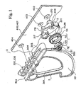
- Fig. 1 is an exploded view of various components constituting a damper device D according to an embodiment.
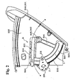
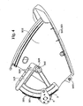
- Fig. 2 through Fig. 4 show examples in which the damper device D damps a movement of a glove box 501 viewed from a side of the glove box 501 in a state that a panel 401 disposed inside an instrument panel with the damper device D is omitted.
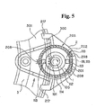
- Fig. 5 shows a state that damping force is generated when only a first part 100 of a damping part 1 constituting the damper device D is rotated.
- Fig. 6 shows a state that the damping force is not generated when the damping part 1 constituting the damper device D is rotated as a whole inside a clutch case 2. That is, Fig. 6 shows the clutch case 2 and the damping part 1 viewed from a side opposite to that in Fig. 2, i.e. from a side facing a side plate 502 of the glove box 501.
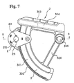
- Fig. 7 shows the damper device D viewed from a side
- Fig. 8 is a sectional view of the damper device D in an assembled state
- Fig. 9 is a perspective view of only the first part 100 constituting the damping part 1 and an oil damper comprising a cylindrical body 112 constituting a second part 110.
- Figs. 10 to 12 show a ring body 114 constituting the damping part 1
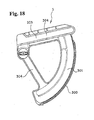
- Figs. 13 to 15 show the clutch case 2
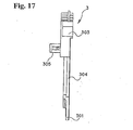
- Figs. 16 to 19 show a rack part 3.
- the damper device D applies damping to the movement of a movable body 500 attached to a fixed body 400 so that the movable body 500 is drawn out and opened.
- the movable body 500 includes a drawing out member such as, for example, a drawer, ash tray, and cup holder, and an opening member such as a door and a cover.
- the damper device D applies damping to an opening movement of a glove box 501 provided inside an automobile compartment. That is, the glove box 501 serves as the movable body 500, and the instrument panel provided with the glove box 501 capable of opening serves as the fixed body 400.
- the damper device includes the damping part 1; the clutch case 2 attached to one of the fixed body 400 and the movable body 500 for retaining the damping part 1; and the rack part 3 moving together with the movable body 500.
- the clutch case 2 is attached to the panel 401 facing an outer surface of a side plate 502 of the glove box 501 disposed in the instrument panel, and the rack part 3 are moved accompanying the opening movement of the glove box 501.
- the damping part 1 comprises the first part 100 and the second part 110.
- the first part 100 and the second part 110 are assembled such that one rotates with the other as a pivot around a common axis x.
- the first part 100 and the second part 110 have a sealed-in space S for filling viscous fluid between one and the other.
- the viscous fluid sealed in the sealed-in space S applies damping to the rotation of the first part 100 and the rotation of the second part 110 around the axis x.
- the first part 100 has a pinion part 101 for engaging the rack part 300 of the rack part 3.
- An outer perimeter part 111 of the second part 110 is formed in a gear.
- the first part 100 is constituted by attaching the pinion part 101 to one end of a shaft body 102 with an axis thereof situated on the axis x while the rotational center of the pinion part 101 is aligned on the axis x, and by providing a plate-shaped wing body 103 protruding two sides in the diametric direction of the shaft body 102 on the other end of the shaft body 102.
- the second part 110 includes a cylindrical body 112 and a ring body 114 for receiving the cylindrical body 112.
- the cylindrical body 102 has both ends closed fluid tightly such that only the pinion part 101 of the first part 100 is protrudes and the remaining portion of the first part 100 is housed therein so that the first part 100 rotates.
- An axis of the cylindrical body 112 is aligned to the axis x.
- the inside of the cylindrical body 112 serves as the sealed-in space S of viscous fluid.
- the viscous fluid housed inside the sealed-in space S generates viscosity resistance on the wing body 103 rotating inside the cylindrical body 112 when the first part 100 rotates, so that the damping is applied to the rotation of the first part 100 and the rotation of the second part 110 around the axis x.
- the viscous fluid typically includes silicon oil or grease oil.
- the cylindrical body 112 has coupling hooks 113 capable of elastic deformation on both sides in the diametric direction thereof.
- the coupling hooks 113 are elastically deformed inwardly once. Then, the coupling hooks 113 engage one side of the ring body 114 by spring-back of the coupling hooks 113 at a position where the cylindrical body 112 is completely inserted into the ring body 114, thereby integrally attaching the cylindrical body 112 to the ring body 114.
- a circular gear part 115 is formed on an outer perimeter part 111 of the ring body 114.
- the outer perimeter part 111 of the second part 110 forms a gear.
- the clutch case 2 has a receiving space 201 for receiving the damping part 1 so that the damping part 1 rotates as a whole.
- the receiving space 201 has an inner diameter y in a direction along a moving direction of the rack part 3 larger than an outer diameter of the second part 110 of the damping part 1, and an inner diameter z in a direction intersecting the moving direction roughly equal to an outer diameter of the second part 110 of the damping part 1.
- a coupling projection 203 is formed on a part of an inner wall part 202 forming the receiving space 201.
- the coupling projection 203 engages the outer perimeter part 111 of the second part 110 of the damping part 1 so that the damping part 1 does not rotate as a whole within the receiving space 201.
- the clutch case 2 has a bottom part 204 facing the receiving space 201, and an open part 205 opening the receiving space 201 on a side opposite to the bottom part 204.
- the receiving space 201 is formed inside an inner wall part 202 formed along a part of an arc of a virtual circle and a protruding piece 207 capable of elastic deformation and protruding from the bottom part 204 at a discontinuous area 206 of the inner wall part 202 such that an inner face thereof is aligned with the arc of the virtual circle.
- a coupling part 208 is formed on an edge of the open part 205.
- the coupling part 208 elastically deforms. Then, the coupling part 208 springs back and engages the edge of the second part 110 of the damping part 1 at a position where the damping part 1 is completely inserted.
- the coupling parts 208 are provided at three places. Two of the places are formed on the inner wall part 202.
- the coupling parts 208 formed on the inner wall part 202 are formed on tips of elastic pieces 209 formed by a part of the inner wall part 202 partitioned by two slots extending toward the bottom part 204 of the receiving space 201 with the slots end free toward outside in the open part 205 of the receiving space 201 so as to stick out toward inside the receiving space 201.
- the other one of the coupling parts 208 in the three places is formed on a tip of the protruding piece 207 so as to stick out into the receiving space 201.
- coupling surfaces of the coupling parts 208 facing the bottom part 204 of the receiving space 201 engage the edge part on the other side of the second part 110 of the damping part 1 in a state that the damping part 1 rotates as a whole inside the receiving space 201, when the damping part 1 is completely inserted into the receiving space 201 such that one surface of the second part 10 of the damping part 1 faces the bottom part 204 of the receiving space 201. Accordingly, it is possible to assemble the damping part 1 into the clutch case 2 with one touch operation.
- the rack part 300 of the rack part 3 engages the pinion part 101 of the first part 100 of the damping part 1 received inside the clutch case 2 throughout the movement of the rack part 3 accompanying the movement of the movable body 500.
- the receiving space 201 of the clutch case 2 has the inner diameter y in the direction of the movement of the rack part 3 greater than the outer diameter of the second part 110 of the damping part 1. Accordingly, when the rack part 3 moves by the movement of the movable body 500, the damping part 1 also moves inside the clutch case 2 accompanying the movement. That is, when the rack part 3 moves forward, the damping part 1 also moves in the direction of forward movement of the rack part 3 inside the receiving space 201 of the clutch case 2 (Fig. 5). On the other hand, when the rack part 3 moves backward, the damping part 1 also moves in the direction of backward movement of the rack part 3 inside the receiving space 201 of the clutch case 2 (Fig. 6).
- the coupling projection 203 is formed on a part of the inner wall part 202 forming the receiving space 201 of the clutch case 2 for engaging the outer perimeter part 111 of the second part 110 of the damping part 1 moving when the rack part 3 moves forward in this manner, i.e. the gear part 115 of the ring body 114. Accordingly, when the movable body 500 is moved so as to move the rack part 3 forward, the rotation of the damping part 1 as a whole inside the clutch case 2 is stopped. Only the first part 100 applied with damping to the rotation by the viscous fluid is rotated with the second part 110 as a shaft bearing in a state in which the pinion part 101 engages the rack part 300 of the rack part 3. As a result, it is possible to apply damping by means of the rack part 3 to the rotation of the movable body 500 in the direction of moving the rack part 3 forward (Fig. 5).
- the damping part 1 moves in the direction of backward movement of the rack part 3 inside the receiving space 201 of the clutch case 2. Accordingly, the engagement between the coupling projections 203 formed on the part of the inner wall part 202 forming the receiving space 201 of the clutch case 2 and the outer perimeter part 111 of the second part 110 of the damping part 1 is released. As a result, the damping part 1 rotates as a whole inside the receiving space 201 inside the clutch case 2 by the movement of the rack part 3 in a state that the pinion part 101 of the first part 100 engages the rack part 300 of the rack part 3. Therefore, the damping is not applied to the movement of the movable body 500 in the direction of moving the rack part 3 backward.
- the rack part 3 has a band-shaped body 301 formed in an arc shape, and moves accompanying movement of the movable body 500 in the direction along the arc.
- the rack part 3 moves forward upwardly in Fig. 2 accompanying opening up of the glove box 501, i.e. the movable body 500, from the state of being in the housed position.
- the coupling projections 203 formed inside the receiving space 201 engage the outer perimeter part 111 of the second part 110 of the damping part 1 moving inside the receiving space 201 upwardly in Fig. 2 (Fig. 5).
- the clutch case 2 is constituted such that the inner diameter of the receiving space 201 is greater than the outer diameter of the second part 110 of the damping part 1 in the vertical direction in Fig. 5.
- the inner diameter of the receiving space 201 is about equal to the outer diameter of the second part 110 of the damping part 1 in the horizontal direction in Fig. 5.
- the coupling projections 203 are formed on a part of the inner wall part 202 forming the receiving space 201 positioned at an upper portion in Fig. 5.
- the coupling projections 203 are formed of three projections 203a having a saw-blade shape.
- a distance between a tip of the coupling projection 203 and the inner wall surface 202 facing opposite to the coupling projection 203 is roughly equal to the outer diameter of the second part 110 of the damping part 1.
- the damping part 1 rotates the first part 100 forward by forward movement of the rack part 3 (Fig. 5).
- the side part on the forward side of the forward rotation is an engaging side part along a straight line passing through the center of rotation of the second part 110, and the opposite side part is a sloping side part (Fig. 5).
- the side part facing the direction of backward rotation of the damping part 1 is an engaging side part along a straight line passing through the center of rotation of the receiving space 201, and the opposite side part is a sloping side part.
- the clutch case 2 has a fixing shaft 210 inserted into a fixing hole 402 of the clutch case 2 formed in the movable body 500 or the fixed body 400.
- the clutch case 2 may have a fixing hole for inserting a fixing shaft of the clutch case 2 formed on the movable body 500 or the fixed body 400. In the case, it is possible to fix the clutch case 2 easily and properly to the movable body 500 or the fixed body 400.
- the clutch case 2 has a main body part 212 having the receiving space 201 therein and a bulging part 213 protruding outwardly from the outer surface part of the main body part 212.
- the bulging part 213 has an installation surface 214 positioned on the same surface as a surface opposite to the open part 205 of the receiving part 201 of the main body part 212.
- a fixing shaft 210 is provided on the installation surface 214 of the main body part 212 such that one end thereof is joined integrally.
- a positioning shaft 216 is provided on the installation surface 214 of the bulging part 213 such that one end thereof is joined integrally.
- the fixing shaft 210 is inserted into a fixing hole 402 formed in the panel 401 disposed inside the instrument panel as the fixed body 400, and the fixing shaft 216 is inserted into a positioning hole 403 formed in the panel 401, so that the clutch case 2 is installed on a surface facing the outer surface of the side plate 502 of the glove box 501 in the instrument panel.
- the fixing shaft 210 has projections 211 capable of elastic deformation and protruding from both sides thereof in the diametric direction.
- the projections 211 are inserted into the fixing hole 402 while being deformed elastically, and engage the hole edge part on the side forward of insertion of the fixing hole 402 by spring-back of the projections 211 at the position where they are completely inserted in the fixing hole 402, whereby they are fitted into the fixing hole 402.
- the rack part 300 of the rack part 3 is formed on one side part along the longitudinal direction of the band-shaped body 301 as described later.
- a holding piece 217 for holding the band-shaped body 301 is formed on the clutch case 2 at a position on one side of the band-shaped body 301.
- the rack part 3 is formed of a band-shaped body 301 curved into an arc.
- the rack part 300 is formed on the edge part positioned on the outside of the curve of the band-shaped body 301.
- One surface of the rack part 3 contacts the front surface opposite to the installation surface 214 of the clutch case 2, and the pinion part 101 of the first part 100 of the damping part 1 disposed in the receiving space 201 of the clutch case 2 engages the rack part 300 of the clutch case 3.
- a support part 218 for supporting the holding piece 217 positioned on the other surface of the rack part 3 is formed respectively on each side of the outer surface part of the main body part 212 of the clutch case 2.
- the rack part 3 is sandwiched to be rotatable between the holding piece 217 supported on the support part 218 and the front surface of the rack part 3.
- the rack part 300 of the rack part 3 always properly engages the pinion part 101 of the first part 100 of the damping part 1 with the holding piece 217.
- the rack part 3 is attached to the fixed body 400 so as to be rotatable. Accordingly, the rack part 300 of the rack part 3 always properly engages the pinion part 101 of the first part 100 of the damping part 1. That is, the rack part 300 of the rack part 3 is not shifted sideways in a direction away from the pinion part 101 of the first part 100 of the damping part 1, and is not shifted in the direction of the axis of rotation of the pinion part 101.
- a groove is formed in the rack part 3 along the direction of movement thereof, and a projection is formed on said holding piece 217 for inserting into the groove, so that the same effect of preventing shifting can be obtained.
- the rack part 3 is positioned such that the rack part 300 thereof always engages the pinion part 101 of the first part 100 of the damping part 1 disposed inside the clutch case 2 throughout the movement thereof.
- the clutch case 2 is attached to the fixed body 400 having the movable body 500 capable of rotating about a rotating shaft.
- the rack part 3 is also attached to the fixed body 400 to be rotatable with a rotating shaft 302 provided at a position different from the rotating shaft 503 of the movable body 500.
- the rack part 300 is arranged along an arc of a virtual circle around the rotating shaft 302 of the rack part 3.
- a groove part 303 is provided and extends from the rotating shaft 302 of the rack part 3 to the rack part 300 for receiving a linking projection 504 provided on the movable body 500.
- a part of the groove part 303 is always positioned on a track of movement ⁇ of the linking projection 504 rotating accompanying rotation of the movable body 500.
- the clutch case 2 is installed on the instrument panel by means of the fixing shaft 210 and positioning shaft 216.
- the rack part 3 have the rack part 300 along the side part on the outside of the curve of the band-shaped body 301 curved into an arc.
- the rack part 300 is arranged along an arc of a virtual circle around the rotating shaft 302 of the rack part 3.
- the rack part 3 is formed by joining the place of formation of the rotating shaft and the band-shaped member 301 by two arms 304 and 304. Between the two arms 304 and 304, an interval is formed in the direction of rotation of the rack part 3.
- the groove part 303 extends directly from the rotating shaft to the rack part 300, and is formed on one of the two arms 304 and 304.
- the rack part 3 has a shaft body 305 inserted into the shaft hole 404 formed in the panel 401 disposed inside the instrument panel to be capable of rotation, and the shaft body 305 functions as the rotating shaft 302.
- the damper device D is installed on the instrument panel such that the linking projection 504 provided on the side plate 502 of the glove box 501 is always received in the groove part 303 of the rack part 3.
- the rotating shaft 302 of the rack part 3 is positioned further upward from the rotating shaft 503 of the glove box 501.
- the damper device D is installed on the instrument panel such that the rotating shaft 302 of the rack part is positioned on the forward side of opening-up of the glove box 501.
- the rack part 300 faces an opposite side, and the arm 304 having the groove 303 is positioned above the other arm 304.
- the glove box 501 moves about the rotating shaft 503 to be opened up from the position before moving (position in Fig. 2) in which the opening of the instrument panel is closed to the position having finished moving (position in Fig. 4).
- the glove box 501 moves to be closed from the position having finished moving to the position before moving.
- the linking projection 504 provided on the outer surface of the side plate 502 of the glove box 501, that is, the side plate 502 having the plate surface along the direction of rotation of the glove box 501, in the position before moving, is positioned on the side of the rack part 300 in the groove part 303 of the rack part 3 of the damper device D installed on the panel 401 disposed inside the instrument panel (Fig. 2).
- the pinion part 101 of the first part 100 of the damping part 1 received inside the clutch case 2 engages the rack part 300 on the upper end side of the rack part 300 (Fig. 2).
- a part of the groove part 303 of the rack part 3 is positioned on the track of movement ⁇ of the linking projection 504 provided on the side of the movable body 500 regardless of a position of rotation of the rack part 3 about the rotating shaft 302.
- the groove part 303 extends along a straight line, not along the track of movement ⁇ of the linking projection 504 about the rotating shaft 503 of the movable body 500 as described above.
- the linking projection 504 moves in the forward direction
- the rack part 3 receiving the linking projection 504 in the groove part 303 moves forward about the rotating shaft or upwardly with the linking projection 504 pushed against the groove wall of the groove part 303.
- the pinion part 101 of the first part 100 of the damping part 1 engages the rack part 3 moving forward in this manner.
- the outer perimeter part 111 of the second part 110 of the damping part 1 engages the coupling projection 203 of the clutch case 2, so that the rotation of the damping part 1 as a whole inside the clutch case 2 is stopped.
- the first part 100 is rotated while receiving damping by the viscous fluid, whereby damping is applied to the forward movement of the rack part 3, that is, the forward movement of the movable body 500.
- the linking projection 504 approaches the rotating shaft 302 of the rack part 3 inside the groove part 303 of the rack part 3 while moving the rack part 3 forward.
- the distance between the rotating shaft 302 of the rack part 3 (fulcrum) and the position of engagement of the pinion part 101 of the first part 100 with the rack part 300 of the rack part 3 (force point) is always constant.
- the damping force of the damping part 1 on the linking projection 504 increases. Accordingly, it is possible to increase the damping force on the movable body 500 when the movable body 500, i.e. the glove box 501, moves in the forward direction.
- the movement is controlled such that the movable body 500 moves comparatively rapidly at the start of forward movement and is gradually slowed toward the end of forward movement
- a damper mechanism according to another embodiment of the present invention will be explained next.
- a glove box 12 (so-called compartment) is provided on the front passenger side of an instrument panel 10 (attachment receiving member) of an automobile.
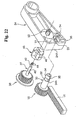
- An opening-and-closing member 20 of the glove box 12 is formed roughly as a box, and has a damper mechanism 14 as shown in Fig. 21(A) and (B).
- the damper mechanism 14 comprises a rack 16 and a gear 18 capable of engaging with each other.
- the rack 16 has a linear form and is installed on a side wall 20A of the opening-and-closing member 20 to move together with the opening-and-closing member 20.
- the opening-and-closing member 20 is capable of rotation about on a shaft part 22, and the rack 16 also rotates about the shaft part 22.
- the gear 18 is installed on one end of a roughly box-shaped base member 24.
- a long hole 26 is provided in one end of the base member 24, and the shaft part 30 of the gear 18 is inserted into the long hole 26 such that the shaft part 30 of the gear 18 slides along the long hole 26.
- a small diameter part 32 is formed on the front end side of the shaft part 30 of the gear 18, and a conical part 34 is formed on the front end part.
- a cut-out part 35 extending along the axial direction of the shaft part 30 is formed on perimeter walls of the small diameter part 32 and the conical part 34, so that the front end side of the shaft part 30 can be contracted.
- the small diameter part 32 and the conical part 34 are contracted.
- a contact surface 34A formed of the small diameter part 32 and the conical part 34 passes through the front end part of a checking wall 36 placed upright from the inner edge part of the long hole 26 and connected to a perimeter wall 24A of the base member 24, the conical part 34 is restored. Then, the contact surface 34A contacts the front end surface of the checking wall 36, and the gear 18 engages the base member 24 to be slidable.
- the other end part of the base member 24 is supported on the instrument panel 10 to be rotatable so that the gear 18 can engage one end part of the rack 16 in a state that the opening-and-closing member 20 is closed.
- a torsion spring (not shown) is disposed on the other end side of the base member 24 for urging the one end side of the base member 24, i.e. a free end, toward the rack 16.
- the base member 24 rotates via the rack 16 and the gear 18, and a position of the rack 16 engaging the gear 18 is shifted.
- the gear 18 is disposed so as to engage the other end part of the rack 16.
- a gear 38 capable of engaging the gear 18 is disposed on the base member 24.
- the gear 18 slides along the long hole 26
- the gear 18 is located in a position capable of engaging or disengaging relative to the gear 38.
- the gear 38 is disposed in a direction that the rack 16 presses the gear 18, so that the gear 18 securely engages the gear 38.
- a coupling part 40 is provided on the outer perimeter of the shaft part 37 of the gear 38 along the axial direction of the shaft part 37 to be capable of elastic deformation.
- a small diameter part 42 is formed on the front end side of the shaft part 37.
- a pair of checking hooks 44 is formed on the front end side of the shaft part 37, and extends moving away from each other toward tips. The checking hooks 44 are capable of elastic deformation.
- a cylindrical damper 46 filled with oil is connected to the shaft part 37. When the shaft part 37 of the gear 38 passes through an axial core part of the damper 46, the checking hooks 44 are contracted in diameter and pass through the axial core part.
- the coupling part 40 engages a coupling receiving part (not shown) provided at the axial core part of the damper 46, so that the damper 46 is connected to the shaft part 30. Accordingly, when the gear 38 rotates, viscosity resistance and the like is applied to a wing 48 disposed inside the damper 46 via the shaft part 37, thereby applying damper force (damping force by the damper 46) to the gear 38.
- a receiving cavity 51 is formed in the base member 24 from a bottom surface of the base member 24 toward inside for receiving the damper 46.
- a backside of a bottom surface of the receiving cavity 51 is flash with a front end surface of the checking wall 36 and a front end surface of the perimeter wall 24A of the base member 24.
- a round hole 50 is formed at the center part of the receiving cavity 51 for passing the shaft part 37, and a checking wall 52 is placed upright from the perimeter part of the round hole 50 on the opposite side of the receiving cavity 51.
- the damper 46 is received inside the receiving cavity 51, and the axial core part of the damper 46 is inserted into the round hole 50 in a state the checking hooks 44 are contracted.
- the checking wall 52 passes the tips of the checking hooks 44, the checking hooks 44 are restored.
- the tips of the checking hooks 44 contact the front end surface of the checking wall 36, and the gear 38 engages the base member 24 in a state of being exposed from the receiving cavity 51.
- One end part of a torsion spring 54 is fixed to the base member 24, and the other end of the torsion spring 54 contacts the gear 18 to urge the gear 18 in the direction away from the gear 38. Accordingly, when the opening-and-closing member 20 is opened, the gear 18 is pressed by the rack 16 in the direction against the force of the torsion spring 54, and engages the gear 38.
- the gear 18 engages the gear 38, so that the damper effect from the damper 46 is transmitted to the gear 18 via the gear 38.
- the damper effect is transmitted to the opening-and-closing member 20 via the rack 16, and the opening-and-closing member 20 is opened slowly.
- the rack 16 is attached to the opening-and-closing member 20 to be rotatable together with the opening-and-closing member 20.
- the gear 18 engages the rack 16, and the gear 38 connected to the damper 46 can engage the gear 18.
- the damper effect is applied to the opening-and-closing member 20 via the gear 38, the gear 18, and the rack 16, in the state that the gear 18 engages the gear 38.
- the base member 24 is installed in the instrument panel 10 to be rotatable, and the gears 18 and 38 are disposed on the base member 24.
- the gear 18 is capable of sliding, and is capable of engaging or disengaging from the gear 38. Accordingly, when the opening-and-closing member 20 is opened, the gear 18 is pressed by the rack 16 moving together with the opening-and-closing member 20, and the gear 18 engages the gear 38, thereby applying the damper effect to the opening-and-closing member 20 so that the opening-and-closing member 20 is opened slowly.
- the long hole 26 is formed in the base member 24.
- the gear 18 slides for transmitting the damper effect to the opening-and-closing member 20, to engage or disengage from the gear 38. Accordingly, it is possible to turn on and off the torque transmission from the damper 46, thereby making the damper mechanism 14 one way.
- the gear 18 is pressed by the rack 16 moving together with the opening-and-closing member 20, and the gear 18 engages the gear 38 to obtain the damper effect. It is possible to reduce an idle time until the damper takes effect by decreasing the distance between the gear 18 and the gear 38. Accordingly, when the opening-and-closing member 20 is closed, even immediately after the opening-and-closing member 20 is opened, the gear 18 engages the gear 38 immediately to obtain the damper effect.
- the rack 16 is formed in a linear shape and the base member 24 is installed on the side wall of the instrument panel 10 to be rotatable. Accordingly, it is possible to adjust a distance between an engaged position P where the gear 18 engages the rack 16 and a rotation central position O of the opening-and-closing member 20. Accordingly, it is possible to adjust a force necessary for opening the opening-and-closing member 20 at the engaged position P of the gear 18 and the rack 16. That is, in the case that the damper force (damping force by the damper member) is constant, if the force necessary for opening the opening-and-closing 20 member is large, the damper effect is reduced as compared with a case that the force is small.
- the distance between the engaged position P of the gear 18 and the rack 16, and the rotation central position O of the opening-and-closing member 20 is changed.
- a distance L 1 between the engaged position P of the rack 16 and the gear 18, and the rotation central position O of the opening-and-closing member 20 is made shorter. Accordingly, the force necessary for opening the opening-and-closing member 20 is made greater at the engaged position P of the gear 18 and the rack 16.
- a distance L 2 between the engaged position P of the rack 16 and the gear 18 and the rotation central position O of the opening-and-closing member 20 is made larger, so that the force is made smaller. Accordingly, at the closed position of the opening-and-closing member 20, the damper effect becomes smaller than the open position. Therefore, it is possible to securely open the opening-and-closing member 20 even in a low-temperature region.
- the rack 16 is formed in a linear shape, and may be formed in an arc shape around the rotation central position O of the opening-and-closing member 20.
- the rack may be formed in an arc shape such that a distance from the rotation central position O of the opening-and-closing member 20 becomes longer as the opening-and-closing member 20 is opened. Accordingly, it is possible to change the damper effect between the closed position and the open position of the opening-and-closing member 20.
- the rack 16 is fixed and the base member 24 rotates.
- the present invention is not limited to this structure, and the rack 16 may rotate, as far as the distance between the engaged position P of the rack 16 and the gear 18 and the rotation central position O of the opening-and-closing member 20 can be changed.
- the opening-and-closing member 20 is formed in a roughly box shape, and the opening-and-closing member 20 may be formed in a plate shape. In this case, the rack 16 may protrude in a direction perpendicular to the door.
Landscapes
- Engineering & Computer Science (AREA)
- Mechanical Engineering (AREA)
- Transmission Devices (AREA)
- Vehicle Step Arrangements And Article Storage (AREA)
- Fluid-Damping Devices (AREA)
- Mechanical Operated Clutches (AREA)
Abstract
- a rack (16) attached to one of the movable body and the fixed body,
- a first gear (18) movably attached to the other of the movable body and the fixed body and engaging the rack,
- a second gear (38) arranged to be engageable with the first gear,
- a damper (46) attached to the second gear for generating the damping force, and
- a base member (24) attached to the other of the fixed body and the fixed body, said base member rotationally holding the second gear and movably supporting the first gear for moving the first gear to engage the second gear when the movable body moves toward a first direction, and for holding the first gear away from the second gear when the movable body moves toward a second direction.
Description
- The present invention relates to a damper mechanism provided on an opening-and-closing member or the like, for example, a glove box of an automobile, for absorbing impact when the opening-and-closing member is opened and closed, and a damper device for damping a movement of a movable body attached to a fixed body so that the movable body is drawn out or opened up.
- In a conventional damper mechanism disclosed in, for example, Japanese Patent Publication (Kokai) No. 05-76894 as shown in Fig. 24(A), a piston 104' is disposed in a cylinder 100' and slides along an inner wall surface of the cylinder 100' with an O-ring 102' in between. An annular cap 106' is provided on a front end of the cylinder 100' and a
guide surface 106A' having a curved surface is formed on an inner surface side of the cap 106'. A first space part 108' is provided between the cap 106' and the piston 104', and a compression spring 110' is disposed in the first space part 108'. - Furthermore, a dividing wall 114' having an air flow-through hole 112' formed in the center thereof is formed on a back end side of the cylinder 100', and a second space part 116' is provided by means of the piston 104' and the dividing wall 114'. A third space part 118' is provided on a back end part of the cylinder 100' between the dividing wall 114'. A valve 120' is provided inside the third space part 118' for closing the flow-through hole 112'. An orifice 122' is formed at the center of the valve 120', and the second space part 116' and the third space part 118' are communicating via the flow-through hole 112' and the orifice 122'.
- One end part of a cord member 124' is attached to a side of the first space part 108' of the piston 104'. As shown in Fig. 24(B), the other end part of the cord member 124' is linked to a linking member 128' of the glove box 126' through the
guide surface 106A'. - With the structure described above, when a push-button type or pull-handle type lock (not shown) is released in a state that the glove box 126' is in the closed state, a rotational moment is applied to the glove box 126'in the opening direction by its own weight. The glove box 126' pulls the cord member 124' and moves the piston 104' in the opening direction (arrow direction) against a force of the compression spring 110'. Accordingly, the cord member 124' is drawn out through the
guide surface 106A', and the glove box 126' begins to open. - At this time, while the glove box 126' receives damping action through fluid resistance of the orifice 122', the glove box 126' is opened in the opening direction, and the piston 104' is drawn out by the cord member 124' and moves up to the open position.
- In the closing operation of the glove box 126', the piston 104' moves in a direction opposite to the opening direction by the force of the compression spring 110' and the valve 120' is opened, so that air passes through the flow-through hole 112'. Accordingly, in a state that the load on the piston 104' is reduced, the cord member 124' is pulled into the cylinder 100', and the glove box 126' is locked at the closed position of the glove box 126'.
- In the conventional damper mechanism disclosed in Japanese Patent Publication (Kokai) No. 05-76894, the linking member 128' is located at the center part of the glove box 126'. Accordingly, there is a difference between a moving path of a free end of the glove box 126' and that of the linking member 128'. That is, the moving path of the linking member 128' is smaller than that of the glove box 126'. Accordingly, there is an idle distance before the damper begins to take effect, thereby making it difficult to follow a sudden movement.
- Further, in a case of an air damper, a dimension of the cylinder 100' changes according to a temperature change, thereby causing a variation in the resistance or losing the damping due to leakage of air. In a case of an oil damper, a viscosity of oil increases in a low-temperature region, thereby increasing a torque and making it difficult to open the glove box 126' by its own weight.
- Also, U.S. Patent No. 5,690,194 and U.S. Patent No. 5,839,548 have disclosed damper devices for damping only when a movable body moves in one direction. Each of the damper devices includes a rack moving together with the movable body and a pinion engaging the rack. A viscous fluid damps the pinion when the pinion rotates.
- In the damper devices disclosed in U.S. Patent No. 5,690,194 and U.S. Patent No. 5,839,548, when the movable body moves in the opposite direction, the engagement between the rack and the pinion is released. Accordingly, it is difficult to securely engage the pinion with the rack again when the movable body moves again in the one direction, thereby requiring a special mechanism in order to assure stable operation.
- In view of the problems described above, an object of the present invention is to provide a one-way type damper mechanism in which an idle time before the damper takes effect is short, and the damper effect is obtained regardless of a temperature.
- Another object of the present invention is to provide a damper mechanism that applies the damping only when a movable body moves in one direction. In the damper mechanism, a rack portion of a rack part moves with a movable body, and always engages a pinion portion of a damping part during the movement of the movable body, so that the damping is securely applied only when the movable body moves in the one direction.
- Further objects and advantages of the invention will be apparent from the following description of the invention.
- In order to attain the objects described above, according to the present invention, a damper device for applying damping to movement of a movable body assembled on a fixed body so as to be capable of drawing-out movement and opening-up movement, and the like, comprises: a damping part; a clutch case attached to one of the fixed body and the movable body in a state having received the damping part; and a rack part moving or relatively moving accompanying movement of the movable body.
- The damping part comprises a first part and a second part, which are assembled so as to be capable of rotation in a manner such that each uses the other as a shaft bearing centered on the same axis of rotation, and has a sealed-in space of viscous fluid between one and the other when assembled, such that damping is applied to the rotation by the viscous fluid sealed in the sealed-in space. The first part has a pinion part for engaging with a rack part of the rack part, and an outer perimeter part of the second part is formed as a gear. The clutch case has a receiving space for receiving the damping part so as to be capable of rotation as a whole. The receiving space is made such that the inner diameter in the direction following the direction of movement of the rack part is made somewhat larger than the outer diameter of the second part of the damping part, and the inner diameter in the direction intersecting this direction of movement is made roughly equal to the outer diameter of the second part of the damping part.
- A coupling projection is formed on a part of an inner wall part forming the receiving space for engaging the outer perimeter part of the second part of the damping part by movement of the damping part within the receiving space accompanying forward movement of the rack part and obstructs rotation of the damping part as a whole within the receiving space. The rack part is positioned in a manner such that the rack part thereof always engages the pinion part of the first part of the damping part received inside the clutch case throughout the movement thereof.
- In the receiving space of the clutch case, because the inner diameter in the direction following the direction of movement of the rack part is made somewhat larger than the outer diameter of the second part of the damping part, when the rack part moves by the movement of the movable body, the damping part also moves inside the clutch case accompanying this. That is, when the rack part moves forward, the damping part also moves toward the forward direction inside the receiving space of the clutch case. Conversely with this, when the rack part moves backward, the damping part also moves toward the backward direction in the receiving space of the clutch case.
- Because the coupling projection is formed on a part of the inner wall part forming the receiving space of the clutch case for engaging the outer perimeter part of the second part of the damping part moving accompanying such movement when the rack part moves forward in this manner, in the case when the movable body moves so as to move the rack part forward, the rotation of the damping part as a whole inside the clutch case is obstructed, and only the first part applied with damping to the rotation by the viscous fluid rotates with the second part as a shaft bearing in a state that the pinion part engages the rack part of the rack part. By this, it is possible to apply damping by means of the rack part to the movement of the movable body in the direction of moving the rack part forward.
- Conversely, in the case when the movable body moves so as to move the rack part backward, because the damping part moves in the direction of backward movement of the rack part inside the receiving space of the clutch case, whereby the engagement between the coupling projection formed on a part of the inner wall part forming the receiving space of the clutch case and the outer perimeter part of the second part of the damping part is released, the damping part rotates as a whole inside the receiving space inside the clutch case by the movement of the rack part in a state that the pinion part of the first part engages the rack part of the rack part. By this, it is possible that damping is not applied to the movement of the movable body in the direction of moving the rack part backward.
- The clutch case has a fixing shaft to be inserted into a clutch case fixing hole formed in the movable body or the fixed body, or a fixing hole into which a clutch case fixing shaft formed on the movable body or the fixed body is inserted. Accordingly, it is possible to fix the clutch case easily and properly to the movable body or the fixed body.
- The rack part is formed on one side part following the longitudinal direction of a band-shaped body; and a holding piece for holding the band-shaped body is formed on the clutch case in a position on one side of the band-shaped body. Accordingly, it is possible that the rack part of the rack part always properly engages the pinion part of the first part of the damping part.
- The clutch case has a bottom part adjacent to the receiving space, and an open part freeing the receiving space on the side opposite the bottom part. A coupling part coupled with an edge part of the second part of the damping part by once being elastically deformed accompanying insertion of the damping part into the receiving space through the open part and then springing back in a position having completely received the damping part is formed on the edge of this open part. Accordingly, it is possible to incorporate the damping part into the clutch case with one touch operation.
- The clutch case is installed on the fixed body having the movable body so as to be capable of rotation centered on a rotating shaft. The rack part is assembled onto the fixed body so to be capable of rotation by a rotating shaft provided at a position different from the rotating shaft of the movable body. The rack part is disposed following an arc of a virtual circle centered on the rotating shaft of the rack part. A groove part for receiving a linking projection provided on the movable body is provided so as to extend for a distance from the side of the rotating shaft of the rack part toward the side of the rack part. A part of the groove part is always positioned on the track of movement of the linking projection rotating accompanying rotation of the movable body.
- Accordingly, when the movable body moves forward, the linking projection moves in the forward direction, and the rack part having received the linking projection in the groove part moves forward centered on the rotating shaft by the linking projection pushed against the groove wall of the groove part. The pinion part of the first part of the damping part engages the rack part moving forward in this manner, and during this forward movement, the outer perimeter part of the second part of the damping part and the coupling projection of the clutch case are engaged, and the rotation of the damping part as a whole inside the clutch case is obstructed. Therefore, only the first part rotates while receiving damping by the viscous fluid, whereby damping is applied to the forward movement of the rack part, i.e. the forward movement of the movable body.
- As the movable body moves forward, the linking projection approaches the rotating shaft of the rack part inside the groove part of the rack part while causing the rack part to move forward. Because the distance between the rotating shaft of the rack part (fulcrum) and the engagement position of the pinion part of the first part with the rack part of the rack part (force point) is always constant, as the linking projection approaches the rotating shaft of the rack part (that is, as the distance between the force point and the action point becomes closer), the damping force of the damping part on the linking projection becomes greater. By this, it is possible to make the damping force on the movable body greater as the movable body moves in the forward direction, and the movement is controlled such that the movable body moves comparatively rapidly at the start of forward movement and that movement is gradually slowed as it approaches the end of forward movement.
- In the damper device according to the invention, it is possible that damping is applied surely only in movement toward one direction of the movable body, while the rack part moving or relatively moving accompanying movement of the movable body and the pinion part of the damping part are always engaged throughout the movement of the rack part.
- According to the invention, a damping mechanism comprises: a rack installed on an opening-and-closing member supported by an installation receiving member and rotating between an open position and a closed position; a first gear capable of engaging the rack; a second gear capable of engaging the first gear and being controlled by a damper; and a base member installed on the installation receiving member and having the second gear disposed thereon, causing the first gear to slide toward the direction of engaging the second gear when the opening-and-closing member is opened toward the open position, and holding the first gear so as to be capable of sliding toward the direction of disengagement from the second gear when the opening-and-closing member is closed toward the closed position.
- In the invention, the rack is installed on the opening-and-closing member supported by the installation receiving member and rotating between the open position and the closed position, and the first gear engages the rack. The second gear controlled by the damper is capable of engaging the first gear, and a damper effect is obtained on the opening-and-closing member by means of the second gear, the first gear, and the rack in a state of engaging the second gear.
- The base member is installed on the installation receiving member, and the second gear is disposed on the base member. When the opening-and-closing member is opened toward the open position, the first gear is pressed by the rack moving together with the opening-and-closing member, and the first gear and the second gear are engaged. By this, a damper effect is applied to the opening-and-closing member, and the opening-and-closing member opens slowly.
- On the other hand, when the opening-and-closing member is closed toward the closed position, the first gear slides toward the direction of disengagement from the second gear such that the damper effect is not transmitted to the first gear. By this, when the opening-and-closing member is closed, the load of the damper is not applied to the opening-and-closing member.
- As described above, in the damper mechanism, an effect as a one-way damper can be obtained assuredly. Also, because the first gear is pressed by the rack moving together with the opening-and-closing member, and the first gear and the second gear are engaged such that a damper effect is obtained, the idle time until the damper begins to take effect can be made shorter by making the distance between the first gear and the second gear shorter. By this, when closing the opening-and-closing member, even if the operation of opening the opening-and-closing member is just attempted, the first gear and the second gear can be engaged immediately, and the damper effect can be obtained.
- According to the invention, the shaft part of the first gear slides following a long hole formed in the base member. The shaft part of the first gear slides following the long hole formed in the base member. Thus, by providing the long hole in the base member and causing the first gear which transmits the damper effect to the opening-and-closing member to slide, it is engaged with or disengaged from the second gear. By this, the torque transmission from damper member which controls the damper is turned on/off, and the damper mechanism is made one way.
- According to the invention, forcing means for forcing the first gear toward the direction of disengaging from the second gear is provided on the base member. The forcing means which forces the first gear toward the direction of disengaging from the second gear is provided on the base member. That is, when opening the opening-and-closing member, the first gear is pressed by the rack in opposition to the force of the forcing means, and it is engaged with the second gear.
- According to the invention, the distance between the engaged position of the first gear with the rack and the rotation central position of the opening-and-closing member is made variable. By making the distance between the engaged position of the first gear with the rack and the rotation central position of the opening-and-closing member variable, the magnitude of the force necessary for opening the opening-and-closing member can be changed in the engaged position of the first gear with the rack.
- That is, in the case when the damper force (damping force by the damper member) is constant, if the magnitude of the force necessary for opening the opening-and-closing member is large, the damper effect is reduced as compared with the case when the magnitude of that force is small.
- Therefore, the distance between the engaged position of the first gear with the rack and the rotation central position of the opening-and-closing member is changed. On the side of the start of opening (closed position) of the opening-and-closing member, the distance between the engaged position of the rack with the first gear and the rotation central position of the opening-and-closing member is made shorter, and the magnitude of the force necessary for opening the opening-and-closing member is made greater in the engaged position of the first gear with the rack. On the side of the end of opening (open position) of the opening-and-closing member, the distance between the engaged position of the rack with the first gear and the rotation central position of the opening-and-closing member is made longer, and the magnitude of the force is made smaller.
- By this, on the side of the closed position of the opening-and-closing member, the damper force becomes smaller than on the side of the open position. Therefore, it becomes possible to open the opening-and-closing member assuredly even in low-temperature regions.
- According to the invention, the rack is linear, and the base member is installed so as to be capable of rocking on the side wall. By making the rack which moves together with the opening-and-closing member linear and installing the base member, to which is attached the first gear which engages with the rack, to be capable of rocking on the attachment receiving member, the distance between the engaged position of the rack with the first gear and the rotation central position of the opening-and-closing member is changed.
- Concretely, on the side of the closed position of the opening-and-closing member, the distance between the engaged position of the first gear with the rack and the rotation central position of the opening-and-closing member is made shorter. On the side of the open position of the opening-and-closing member, the distance between the engaged position of the first gear with the rack and the rotation central position of the opening-and-closing member is made longer.
- Because the present invention is constituted as mentioned above, the effect as a one-way damper can be obtained assuredly. Also, because the first gear is pressed by the rack which moves together with the opening-and-closing member and the first gear and the second gear are engaged such that the damper effect is obtained, the idle time until the damper begins to take effect can be made shorter by making the distance between the first gear and the second gear shorter. By this, when closing the opening-and-closing member, even if the operation of opening the opening-and-closing member is just attempted, the first gear and the second gear can be engaged immediately such that the damper effect is obtained.
- The torque transmission due to the damper mechanism which controls the damper is turned on/off, and the damper mechanism is made one way. When opening the opening-and-closing member, the first gear is pressed by the rack in opposition to the force of the forcing means, and it is engaged with the second gear.
- The distance between the engaged position of the first gear with the rack and the rotation central position of the opening-and-closing member is changed. On the side of the closed position of the opening-and-closing member, the distance between the engaged position of the rack with the first gear and the rotation central position of the opening-and-closing member is made shorter, and the magnitude of the force necessary for opening the opening-and-closing member is made greater in the engaged position of the first gear with the rack. On the side of the open position of the opening-and-closing member, the distance between the engaged position of the rack with the first gear and the rotation central position of the opening-and-closing member is made longer, and the magnitude of the force is made smaller. By this, on the side of the closed position of the opening-and-closing member, the damper effect can be made smaller than on the side of the open position. Therefore, it becomes possible to open the opening-and-closing member assuredly even in low-temperature regions.
-
- Fig. 1 is an exploded perspective view of a damper device D of the invention;
- Fig. 2 is a side view of the damper device in a use state;
- Fig. 3 is a side view of the damper device in a use state;
- Fig. 4 is a side view of the damper device in a use state;
- Fig. 5 is a view showing an essential part of the damper device D;
- Fig. 6 is a view showing an essential part of the damper device D;
- Fig. 7 is a side view of the damper device;
- Fig. 8 is a sectional view take along line 8-8 in Fig. 7;
- Fig. 9 is a perspective view of oil damper components constituting a damping
part 1; - Fig. 10 is a backside view of a
ring body 114 constituting the dampingpart 1; - Fig. 11 is a partial sectional right side view of the ring body;
- Fig. 12 is a front view of the ring body;
- Fig. 13 is a front view of a
clutch case 2; - Fig. 14 is a sectional view taken along line 14-14 in Fig. 13;
- Fig. 15 is a sectional view taken along line 15-15 in Fig. 13;
- Fig. 16 is a backside view of a
rack part 3; - Fig. 17 is a side view of the
rack part 3; - Fig. 18 is a front view of the
rack part 3; - Fig. 19 is a sectional view taken along line 19-19 in Fig. 16;
- Fig. 20 is a perspective view of an opening-and-closing member of a glove box having a damper mechanism according to an embodiment of the present invention;
- Figs. 21(A) and 21(B) are side views showing the damper mechanism according to the embodiment of the present invention;
- Fig. 22 is an exploded perspective view showing the damper mechanism according to the embodiment of the present invention.
- Figs. 23(A) and 23(B) are enlarged views of Figs. 21(A) and 21(B), wherein Fig. 23(A) shows a state that gears constituting the damper mechanism are disengaged, and Fig. 23(B) shows a state that the gears are engaged; and
- Figs. 24(A) and 24(B) are views showing a conventional damper mechanism, wherein Fig. 24(A) is a sectional view thereof, and Fig. 24(B) is a side view of an opening-and-closing member of a glove box using the damper mechanism.
- Hereunder, embodiments of the present invention will be explained with reference to the accompanying drawings.
- Fig. 1 is an exploded view of various components constituting a damper device D according to an embodiment. Fig. 2 through Fig. 4 show examples in which the damper device D damps a movement of a glove box 501 viewed from a side of the glove box 501 in a state that a panel 401 disposed inside an instrument panel with the damper device D is omitted. Fig. 5 shows a state that damping force is generated when only a
first part 100 of a dampingpart 1 constituting the damper device D is rotated. Fig. 6 shows a state that the damping force is not generated when the dampingpart 1 constituting the damper device D is rotated as a whole inside aclutch case 2. That is, Fig. 6 shows theclutch case 2 and the dampingpart 1 viewed from a side opposite to that in Fig. 2, i.e. from a side facing aside plate 502 of the glove box 501. - Fig. 7 shows the damper device D viewed from a side, and Fig. 8 is a sectional view of the damper device D in an assembled state. Fig. 9 is a perspective view of only the
first part 100 constituting the dampingpart 1 and an oil damper comprising acylindrical body 112 constituting asecond part 110. Figs. 10 to 12 show aring body 114 constituting the dampingpart 1, Figs. 13 to 15 show theclutch case 2, and Figs. 16 to 19 show arack part 3. - According to the embodiment, the damper device D applies damping to the movement of a movable body 500 attached to a fixed body 400 so that the movable body 500 is drawn out and opened. The movable body 500 includes a drawing out member such as, for example, a drawer, ash tray, and cup holder, and an opening member such as a door and a cover. In the embodiment, the damper device D applies damping to an opening movement of a glove box 501 provided inside an automobile compartment. That is, the glove box 501 serves as the movable body 500, and the instrument panel provided with the glove box 501 capable of opening serves as the fixed body 400.
- The damper device includes the damping
part 1; theclutch case 2 attached to one of the fixed body 400 and the movable body 500 for retaining the dampingpart 1; and therack part 3 moving together with the movable body 500. In the embodiment, theclutch case 2 is attached to the panel 401 facing an outer surface of aside plate 502 of the glove box 501 disposed in the instrument panel, and therack part 3 are moved accompanying the opening movement of the glove box 501. - The damping
part 1 comprises thefirst part 100 and thesecond part 110. Thefirst part 100 and thesecond part 110 are assembled such that one rotates with the other as a pivot around a common axis x. Thefirst part 100 and thesecond part 110 have a sealed-in space S for filling viscous fluid between one and the other. The viscous fluid sealed in the sealed-in space S applies damping to the rotation of thefirst part 100 and the rotation of thesecond part 110 around the axis x. - The
first part 100 has apinion part 101 for engaging therack part 300 of therack part 3. An outer perimeter part 111 of thesecond part 110 is formed in a gear. In the embodiment, thefirst part 100 is constituted by attaching thepinion part 101 to one end of ashaft body 102 with an axis thereof situated on the axis x while the rotational center of thepinion part 101 is aligned on the axis x, and by providing a plate-shapedwing body 103 protruding two sides in the diametric direction of theshaft body 102 on the other end of theshaft body 102. - The
second part 110 includes acylindrical body 112 and aring body 114 for receiving thecylindrical body 112. Thecylindrical body 102 has both ends closed fluid tightly such that only thepinion part 101 of thefirst part 100 is protrudes and the remaining portion of thefirst part 100 is housed therein so that thefirst part 100 rotates. An axis of thecylindrical body 112 is aligned to the axis x. In the embodiment, the inside of thecylindrical body 112 serves as the sealed-in space S of viscous fluid. The viscous fluid housed inside the sealed-in space S generates viscosity resistance on thewing body 103 rotating inside thecylindrical body 112 when thefirst part 100 rotates, so that the damping is applied to the rotation of thefirst part 100 and the rotation of thesecond part 110 around the axis x. The viscous fluid typically includes silicon oil or grease oil. - In the embodiment, the
cylindrical body 112 has coupling hooks 113 capable of elastic deformation on both sides in the diametric direction thereof. When thecylindrical body 112 is inserted into thering body 114, the coupling hooks 113 are elastically deformed inwardly once. Then, the coupling hooks 113 engage one side of thering body 114 by spring-back of the coupling hooks 113 at a position where thecylindrical body 112 is completely inserted into thering body 114, thereby integrally attaching thecylindrical body 112 to thering body 114. - A circular gear part 115 is formed on an outer perimeter part 111 of the
ring body 114. When thecylindrical body 112 is attached to thering body 114, the outer perimeter part 111 of thesecond part 110 forms a gear. - The
clutch case 2 has a receivingspace 201 for receiving the dampingpart 1 so that the dampingpart 1 rotates as a whole. The receivingspace 201 has an inner diameter y in a direction along a moving direction of therack part 3 larger than an outer diameter of thesecond part 110 of the dampingpart 1, and an inner diameter z in a direction intersecting the moving direction roughly equal to an outer diameter of thesecond part 110 of the dampingpart 1. - A
coupling projection 203 is formed on a part of aninner wall part 202 forming the receivingspace 201. When the dampingpart 1 moves within the receivingspace 201 accompanying the forward movement of therack part 3, thecoupling projection 203 engages the outer perimeter part 111 of thesecond part 110 of the dampingpart 1 so that the dampingpart 1 does not rotate as a whole within the receivingspace 201. - In the embodiment, the
clutch case 2 has abottom part 204 facing the receivingspace 201, and anopen part 205 opening the receivingspace 201 on a side opposite to thebottom part 204. The receivingspace 201 is formed inside aninner wall part 202 formed along a part of an arc of a virtual circle and aprotruding piece 207 capable of elastic deformation and protruding from thebottom part 204 at adiscontinuous area 206 of theinner wall part 202 such that an inner face thereof is aligned with the arc of the virtual circle. - Also, in the embodiment, a
coupling part 208 is formed on an edge of theopen part 205. When the dampingpart 1 is inserted into the receivingspace 201 through theopen part 205, thecoupling part 208 elastically deforms. Then, thecoupling part 208 springs back and engages the edge of thesecond part 110 of the dampingpart 1 at a position where the dampingpart 1 is completely inserted. Thecoupling parts 208 are provided at three places. Two of the places are formed on theinner wall part 202. Thecoupling parts 208 formed on theinner wall part 202 are formed on tips ofelastic pieces 209 formed by a part of theinner wall part 202 partitioned by two slots extending toward thebottom part 204 of the receivingspace 201 with the slots end free toward outside in theopen part 205 of the receivingspace 201 so as to stick out toward inside the receivingspace 201. The other one of thecoupling parts 208 in the three places is formed on a tip of the protrudingpiece 207 so as to stick out into the receivingspace 201. - Also, in the embodiment, coupling surfaces of the
coupling parts 208 facing thebottom part 204 of the receivingspace 201 engage the edge part on the other side of thesecond part 110 of the dampingpart 1 in a state that the dampingpart 1 rotates as a whole inside the receivingspace 201, when the dampingpart 1 is completely inserted into the receivingspace 201 such that one surface of thesecond part 10 of the dampingpart 1 faces thebottom part 204 of the receivingspace 201. Accordingly, it is possible to assemble the dampingpart 1 into theclutch case 2 with one touch operation. - The
rack part 300 of therack part 3 engages thepinion part 101 of thefirst part 100 of the dampingpart 1 received inside theclutch case 2 throughout the movement of therack part 3 accompanying the movement of the movable body 500. - The receiving
space 201 of theclutch case 2 has the inner diameter y in the direction of the movement of therack part 3 greater than the outer diameter of thesecond part 110 of the dampingpart 1. Accordingly, when therack part 3 moves by the movement of the movable body 500, the dampingpart 1 also moves inside theclutch case 2 accompanying the movement. That is, when therack part 3 moves forward, the dampingpart 1 also moves in the direction of forward movement of therack part 3 inside the receivingspace 201 of the clutch case 2 (Fig. 5). On the other hand, when therack part 3 moves backward, the dampingpart 1 also moves in the direction of backward movement of therack part 3 inside the receivingspace 201 of the clutch case 2 (Fig. 6). - The
coupling projection 203 is formed on a part of theinner wall part 202 forming the receivingspace 201 of theclutch case 2 for engaging the outer perimeter part 111 of thesecond part 110 of the dampingpart 1 moving when therack part 3 moves forward in this manner, i.e. the gear part 115 of thering body 114. Accordingly, when the movable body 500 is moved so as to move therack part 3 forward, the rotation of the dampingpart 1 as a whole inside theclutch case 2 is stopped. Only thefirst part 100 applied with damping to the rotation by the viscous fluid is rotated with thesecond part 110 as a shaft bearing in a state in which thepinion part 101 engages therack part 300 of therack part 3. As a result, it is possible to apply damping by means of therack part 3 to the rotation of the movable body 500 in the direction of moving therack part 3 forward (Fig. 5). - Conversely, when the movable body 500 moves so as to move the
rack part 3 backward, the dampingpart 1 moves in the direction of backward movement of therack part 3 inside the receivingspace 201 of theclutch case 2. Accordingly, the engagement between thecoupling projections 203 formed on the part of theinner wall part 202 forming the receivingspace 201 of theclutch case 2 and the outer perimeter part 111 of thesecond part 110 of the dampingpart 1 is released. As a result, the dampingpart 1 rotates as a whole inside the receivingspace 201 inside theclutch case 2 by the movement of therack part 3 in a state that thepinion part 101 of thefirst part 100 engages therack part 300 of therack part 3. Therefore, the damping is not applied to the movement of the movable body 500 in the direction of moving therack part 3 backward. - In the embodiment, as described later, the
rack part 3 has a band-shapedbody 301 formed in an arc shape, and moves accompanying movement of the movable body 500 in the direction along the arc. Therack part 3 moves forward upwardly in Fig. 2 accompanying opening up of the glove box 501, i.e. the movable body 500, from the state of being in the housed position. By this forward movement, thecoupling projections 203 formed inside the receivingspace 201 engage the outer perimeter part 111 of thesecond part 110 of the dampingpart 1 moving inside the receivingspace 201 upwardly in Fig. 2 (Fig. 5). - That is, in the embodiment, the
clutch case 2 is constituted such that the inner diameter of the receivingspace 201 is greater than the outer diameter of thesecond part 110 of the dampingpart 1 in the vertical direction in Fig. 5. The inner diameter of the receivingspace 201 is about equal to the outer diameter of thesecond part 110 of the dampingpart 1 in the horizontal direction in Fig. 5. Thecoupling projections 203 are formed on a part of theinner wall part 202 forming the receivingspace 201 positioned at an upper portion in Fig. 5. - In the embodiment, the
coupling projections 203 are formed of threeprojections 203a having a saw-blade shape. A distance between a tip of thecoupling projection 203 and theinner wall surface 202 facing opposite to thecoupling projection 203 is roughly equal to the outer diameter of thesecond part 110 of the dampingpart 1. The dampingpart 1 rotates thefirst part 100 forward by forward movement of the rack part 3 (Fig. 5). In the teeth of the gear part 115 of thesecond part 110, the side part on the forward side of the forward rotation is an engaging side part along a straight line passing through the center of rotation of thesecond part 110, and the opposite side part is a sloping side part (Fig. 5). - In the
coupling projections 203, the side part facing the direction of backward rotation of the dampingpart 1 is an engaging side part along a straight line passing through the center of rotation of the receivingspace 201, and the opposite side part is a sloping side part. When therack part 3 moves forward such that thefirst part 100 of the dampingpart 1 rotates forward, the engaging side parts of the teeth of the gear part 115 of thesecond part 110 of the dampingpart 1 engage the engaging side parts of thecoupling projections 203 securely, and the rotation of the dampingpart 1 as a whole is stopped (Fig. 5). On the other hand, when therack part 3 moves backward such that the dampingpart 1 rotates backward, the sloping side parts of the teeth of the gear part 115 of thesecond part 110 of the dampingpart 1 collide with the sloping side parts of thecoupling projections 203. Accordingly, the dampingpart 1 rotates as a whole inside the receivingspace 201, and there is no obstruction to the rotation as a whole (Fig. 6). - In the embodiment, the
clutch case 2 has a fixingshaft 210 inserted into a fixinghole 402 of theclutch case 2 formed in the movable body 500 or the fixed body 400. Theclutch case 2 may have a fixing hole for inserting a fixing shaft of theclutch case 2 formed on the movable body 500 or the fixed body 400. In the case, it is possible to fix theclutch case 2 easily and properly to the movable body 500 or the fixed body 400. - In the embodiment, the
clutch case 2 has amain body part 212 having the receivingspace 201 therein and abulging part 213 protruding outwardly from the outer surface part of themain body part 212. The bulgingpart 213 has aninstallation surface 214 positioned on the same surface as a surface opposite to theopen part 205 of the receivingpart 201 of themain body part 212. A fixingshaft 210 is provided on theinstallation surface 214 of themain body part 212 such that one end thereof is joined integrally. Apositioning shaft 216 is provided on theinstallation surface 214 of the bulgingpart 213 such that one end thereof is joined integrally. The fixingshaft 210 is inserted into a fixinghole 402 formed in the panel 401 disposed inside the instrument panel as the fixed body 400, and the fixingshaft 216 is inserted into apositioning hole 403 formed in the panel 401, so that theclutch case 2 is installed on a surface facing the outer surface of theside plate 502 of the glove box 501 in the instrument panel. - In the embodiment, the fixing
shaft 210 hasprojections 211 capable of elastic deformation and protruding from both sides thereof in the diametric direction. Theprojections 211 are inserted into the fixinghole 402 while being deformed elastically, and engage the hole edge part on the side forward of insertion of the fixinghole 402 by spring-back of theprojections 211 at the position where they are completely inserted in the fixinghole 402, whereby they are fitted into the fixinghole 402. - Also, in the embodiment, the
rack part 300 of therack part 3 is formed on one side part along the longitudinal direction of the band-shapedbody 301 as described later. A holdingpiece 217 for holding the band-shapedbody 301 is formed on theclutch case 2 at a position on one side of the band-shapedbody 301. Specifically, therack part 3 is formed of a band-shapedbody 301 curved into an arc. Therack part 300 is formed on the edge part positioned on the outside of the curve of the band-shapedbody 301. One surface of therack part 3 contacts the front surface opposite to theinstallation surface 214 of theclutch case 2, and thepinion part 101 of thefirst part 100 of the dampingpart 1 disposed in the receivingspace 201 of theclutch case 2 engages therack part 300 of theclutch case 3. Asupport part 218 for supporting the holdingpiece 217 positioned on the other surface of therack part 3 is formed respectively on each side of the outer surface part of themain body part 212 of theclutch case 2. Therack part 3 is sandwiched to be rotatable between the holdingpiece 217 supported on thesupport part 218 and the front surface of therack part 3. - Accordingly, the
rack part 300 of therack part 3 always properly engages thepinion part 101 of thefirst part 100 of the dampingpart 1 with the holdingpiece 217. - In the embodiment, the
rack part 3 is attached to the fixed body 400 so as to be rotatable. Accordingly, therack part 300 of therack part 3 always properly engages thepinion part 101 of thefirst part 100 of the dampingpart 1. That is, therack part 300 of therack part 3 is not shifted sideways in a direction away from thepinion part 101 of thefirst part 100 of the dampingpart 1, and is not shifted in the direction of the axis of rotation of thepinion part 101. - In a case that the
rack part 3 is not attached to the fixed body 400 to be rotatable, a groove is formed in therack part 3 along the direction of movement thereof, and a projection is formed on said holdingpiece 217 for inserting into the groove, so that the same effect of preventing shifting can be obtained. - The
rack part 3 is positioned such that therack part 300 thereof always engages thepinion part 101 of thefirst part 100 of the dampingpart 1 disposed inside theclutch case 2 throughout the movement thereof. Theclutch case 2 is attached to the fixed body 400 having the movable body 500 capable of rotating about a rotating shaft. Therack part 3 is also attached to the fixed body 400 to be rotatable with arotating shaft 302 provided at a position different from therotating shaft 503 of the movable body 500. Therack part 300 is arranged along an arc of a virtual circle around therotating shaft 302 of therack part 3. Agroove part 303 is provided and extends from therotating shaft 302 of therack part 3 to therack part 300 for receiving a linkingprojection 504 provided on the movable body 500. A part of thegroove part 303 is always positioned on a track of movement α of the linkingprojection 504 rotating accompanying rotation of the movable body 500. - Concretely, the
clutch case 2 is installed on the instrument panel by means of the fixingshaft 210 andpositioning shaft 216. - On the other hand, the
rack part 3 have therack part 300 along the side part on the outside of the curve of the band-shapedbody 301 curved into an arc. Therack part 300 is arranged along an arc of a virtual circle around therotating shaft 302 of therack part 3. Therack part 3 is formed by joining the place of formation of the rotating shaft and the band-shapedmember 301 by twoarms arms rack part 3. Thegroove part 303 extends directly from the rotating shaft to therack part 300, and is formed on one of the twoarms rack part 3 has ashaft body 305 inserted into theshaft hole 404 formed in the panel 401 disposed inside the instrument panel to be capable of rotation, and theshaft body 305 functions as therotating shaft 302. - In the embodiment, the damper device D is installed on the instrument panel such that the linking
projection 504 provided on theside plate 502 of the glove box 501 is always received in thegroove part 303 of therack part 3. - In the embodiment, the
rotating shaft 302 of therack part 3 is positioned further upward from therotating shaft 503 of the glove box 501. The damper device D is installed on the instrument panel such that therotating shaft 302 of the rack part is positioned on the forward side of opening-up of the glove box 501. Therack part 300 faces an opposite side, and thearm 304 having thegroove 303 is positioned above theother arm 304. The glove box 501 moves about therotating shaft 503 to be opened up from the position before moving (position in Fig. 2) in which the opening of the instrument panel is closed to the position having finished moving (position in Fig. 4). The glove box 501 moves to be closed from the position having finished moving to the position before moving. - The linking
projection 504 provided on the outer surface of theside plate 502 of the glove box 501, that is, theside plate 502 having the plate surface along the direction of rotation of the glove box 501, in the position before moving, is positioned on the side of therack part 300 in thegroove part 303 of therack part 3 of the damper device D installed on the panel 401 disposed inside the instrument panel (Fig. 2). In this state, thepinion part 101 of thefirst part 100 of the dampingpart 1 received inside theclutch case 2 engages therack part 300 on the upper end side of the rack part 300 (Fig. 2). A part of thegroove part 303 of therack part 3 is positioned on the track of movement α of the linkingprojection 504 provided on the side of the movable body 500 regardless of a position of rotation of therack part 3 about therotating shaft 302. Thegroove part 303 extends along a straight line, not along the track of movement α of the linkingprojection 504 about therotating shaft 503 of the movable body 500 as described above. - Accordingly, when the movable body 500 moves forward or the glove box 501 moves to be opened up, the linking
projection 504 moves in the forward direction, and therack part 3 receiving the linkingprojection 504 in thegroove part 303 moves forward about the rotating shaft or upwardly with the linkingprojection 504 pushed against the groove wall of thegroove part 303. Thepinion part 101 of thefirst part 100 of the dampingpart 1 engages therack part 3 moving forward in this manner. During the forward movement, the outer perimeter part 111 of thesecond part 110 of the dampingpart 1 engages thecoupling projection 203 of theclutch case 2, so that the rotation of the dampingpart 1 as a whole inside theclutch case 2 is stopped. - Therefore, only the
first part 100 is rotated while receiving damping by the viscous fluid, whereby damping is applied to the forward movement of therack part 3, that is, the forward movement of the movable body 500. When the movable body 500 moves forward, the linkingprojection 504 approaches therotating shaft 302 of therack part 3 inside thegroove part 303 of therack part 3 while moving therack part 3 forward. The distance between therotating shaft 302 of the rack part 3 (fulcrum) and the position of engagement of thepinion part 101 of thefirst part 100 with therack part 300 of the rack part 3 (force point) is always constant. Accordingly, when the linkingprojection 504 approaches therotating shaft 302 of the rack part 3 (that is, as the force point becomes closer to the action point), the damping force of the dampingpart 1 on the linkingprojection 504 increases. Accordingly, it is possible to increase the damping force on the movable body 500 when the movable body 500, i.e. the glove box 501, moves in the forward direction. The movement is controlled such that the movable body 500 moves comparatively rapidly at the start of forward movement and is gradually slowed toward the end of forward movement - When the movable body 500 moves backward after moves forward completely or the glove box 501 moves to be closed, the linking
projection 504 moves in the backward direction, and therack part 3 receiving the linkingprojection 504 in thegroove part 303 moves backward about therotating shaft 302 or rotates downwardly. During the backward movement, because the outer perimeter part 111 of thesecond part 110 of the dampingpart 1 does not engage thecoupling projection 203 of theclutch case 2, the dampingpart 1 rotates as a whole inside theclutch case 2. Accordingly, damping is not applied to the backward movement of therack part 3, that is, the forward and backward movement of the movable body 500. - A damper mechanism according to another embodiment of the present invention will be explained next. As shown in Fig. 20, a glove box 12 (so-called compartment) is provided on the front passenger side of an instrument panel 10 (attachment receiving member) of an automobile. An opening-and-closing
member 20 of theglove box 12 is formed roughly as a box, and has adamper mechanism 14 as shown in Fig. 21(A) and (B). Thedamper mechanism 14 comprises arack 16 and agear 18 capable of engaging with each other. - The
rack 16 has a linear form and is installed on aside wall 20A of the opening-and-closingmember 20 to move together with the opening-and-closingmember 20. The opening-and-closingmember 20 is capable of rotation about on ashaft part 22, and therack 16 also rotates about theshaft part 22. - As shown in Figs. 22, 23(A) and (B) (Figs. 23(A) and 22 (B) are partially enlarged views of Figs. 21(A) and 21(B)), the
gear 18 is installed on one end of a roughly box-shapedbase member 24. Along hole 26 is provided in one end of thebase member 24, and theshaft part 30 of thegear 18 is inserted into thelong hole 26 such that theshaft part 30 of thegear 18 slides along thelong hole 26. Asmall diameter part 32 is formed on the front end side of theshaft part 30 of thegear 18, and aconical part 34 is formed on the front end part. A cut-outpart 35 extending along the axial direction of theshaft part 30 is formed on perimeter walls of thesmall diameter part 32 and theconical part 34, so that the front end side of theshaft part 30 can be contracted. - When the
shaft part 30 is inserted into thelong hole 26, thesmall diameter part 32 and theconical part 34 are contracted. When acontact surface 34A formed of thesmall diameter part 32 and theconical part 34 passes through the front end part of a checkingwall 36 placed upright from the inner edge part of thelong hole 26 and connected to aperimeter wall 24A of thebase member 24, theconical part 34 is restored. Then, thecontact surface 34A contacts the front end surface of the checkingwall 36, and thegear 18 engages thebase member 24 to be slidable. - As shown in Fig. 21(A), the other end part of the
base member 24 is supported on theinstrument panel 10 to be rotatable so that thegear 18 can engage one end part of therack 16 in a state that the opening-and-closingmember 20 is closed. A torsion spring (not shown) is disposed on the other end side of thebase member 24 for urging the one end side of thebase member 24, i.e. a free end, toward therack 16. - When the opening-and-closing
member 20 opens, thebase member 24 rotates via therack 16 and thegear 18, and a position of therack 16 engaging thegear 18 is shifted. As shown in Fig. 21(B), in the position at the end of opening (open position) of the opening-and-closingmember 20, thegear 18 is disposed so as to engage the other end part of therack 16. - As shown in Figs. 22, 23(A) and 23(B), a
gear 38 capable of engaging thegear 18 is disposed on thebase member 24. When thegear 18 slides along thelong hole 26, thegear 18 is located in a position capable of engaging or disengaging relative to thegear 38. In the position where thegear 18 engages thegear 38, when the opening-and-closing member 20 (see Figs. 21 (A) and 21(B)) is opened, thegear 38 is disposed in a direction that therack 16 presses thegear 18, so that thegear 18 securely engages thegear 38. - A
coupling part 40 is provided on the outer perimeter of theshaft part 37 of thegear 38 along the axial direction of theshaft part 37 to be capable of elastic deformation. Asmall diameter part 42 is formed on the front end side of theshaft part 37. A pair of checking hooks 44 is formed on the front end side of theshaft part 37, and extends moving away from each other toward tips. The checking hooks 44 are capable of elastic deformation. Acylindrical damper 46 filled with oil is connected to theshaft part 37. When theshaft part 37 of thegear 38 passes through an axial core part of thedamper 46, the checking hooks 44 are contracted in diameter and pass through the axial core part. Thecoupling part 40 engages a coupling receiving part (not shown) provided at the axial core part of thedamper 46, so that thedamper 46 is connected to theshaft part 30. Accordingly, when thegear 38 rotates, viscosity resistance and the like is applied to awing 48 disposed inside thedamper 46 via theshaft part 37, thereby applying damper force (damping force by the damper 46) to thegear 38. - A receiving
cavity 51 is formed in thebase member 24 from a bottom surface of thebase member 24 toward inside for receiving thedamper 46. A backside of a bottom surface of the receivingcavity 51 is flash with a front end surface of the checkingwall 36 and a front end surface of theperimeter wall 24A of thebase member 24. Around hole 50 is formed at the center part of the receivingcavity 51 for passing theshaft part 37, and a checkingwall 52 is placed upright from the perimeter part of theround hole 50 on the opposite side of the receivingcavity 51. - The
damper 46 is received inside the receivingcavity 51, and the axial core part of thedamper 46 is inserted into theround hole 50 in a state the checking hooks 44 are contracted. When the checkingwall 52 passes the tips of the checking hooks 44, the checking hooks 44 are restored. Then, the tips of the checking hooks 44 contact the front end surface of the checkingwall 36, and thegear 38 engages thebase member 24 in a state of being exposed from the receivingcavity 51. One end part of atorsion spring 54 is fixed to thebase member 24, and the other end of thetorsion spring 54 contacts thegear 18 to urge thegear 18 in the direction away from thegear 38. Accordingly, when the opening-and-closingmember 20 is opened, thegear 18 is pressed by therack 16 in the direction against the force of thetorsion spring 54, and engages thegear 38. - An operation of opening the opening-and-closing
member 20 of the glove box using the damper mechanism according to the embodiment of the present invention will be explained next. - As shown in Figs. 21 (A) and 23(A), in the state that the opening-and-closing
member 20 is closed, thegear 18 engages one end part of therack 16. Thegear 18 is also urged by thetorsion spring 54 in the direction away from thegear 38, and is disengaged from thegear 38. When the opening-and-closingmember 20 is opened from this state, as shown in Fig. 21(B) and Fig. 23(B), therack 16 rotates about theshaft part 22 together with the opening-and-closingmember 20. Thegear 18 is pressed by therack 16 in the direction against the force of thetorsion spring 54, and slides inside thelong hole 26 of thebase member 24. Accordingly, thegear 18 engages thegear 38, so that the damper effect from thedamper 46 is transmitted to thegear 18 via thegear 38. The damper effect is transmitted to the opening-and-closingmember 20 via therack 16, and the opening-and-closingmember 20 is opened slowly. - At this time, as the opening-and-closing
member 20 is opened, the engagement position between therack 16 and thegear 18 shifts from one end part of therack 16 to the other end part of therack 16. One end of thebase member 24 rotates toward the direction away from the rotation central position O of the opening-and-closingmember 20. - An operation of closing the opening-and-closing
member 20 of the glove box using the damper mechanism according to the embodiment of the present invention will be explained next. - When the opening-and-closing
member 20 is closed, therack 16 moves toward the direction away from thegear 18, so that the force no longer works in the direction of pressing thegear 18 toward thegear 38. Accordingly, thegear 18 slides toward the direction away from thegear 38 by the force of the torsion spring 54 (see Fig. 23(A)). Accordingly, the damper effect from thedamper 46 is not transmitted to thegear 18. That is, the load of thedamper 46 is not applied when the opening-and-closingmember 20 is closed. - An operation of the damper mechanism according to the embodiment of the present invention will be explained next. As shown in Fig. 21(B) and Fig. 23(B), the
rack 16 is attached to the opening-and-closingmember 20 to be rotatable together with the opening-and-closingmember 20. Thegear 18 engages therack 16, and thegear 38 connected to thedamper 46 can engage thegear 18. The damper effect is applied to the opening-and-closingmember 20 via thegear 38, thegear 18, and therack 16, in the state that thegear 18 engages thegear 38. - The
base member 24 is installed in theinstrument panel 10 to be rotatable, and thegears base member 24. Thegear 18 is capable of sliding, and is capable of engaging or disengaging from thegear 38. Accordingly, when the opening-and-closingmember 20 is opened, thegear 18 is pressed by therack 16 moving together with the opening-and-closingmember 20, and thegear 18 engages thegear 38, thereby applying the damper effect to the opening-and-closingmember 20 so that the opening-and-closingmember 20 is opened slowly. - As shown in Fig. 21(A) and Fig. 23(A), when the opening-and-closing
member 20 is closed, thegear 18 slides in the direction of disengaging from thegear 38, so that the damper effect is not transmitted to thegear 18. Accordingly, when the opening-and-closingmember 20 is closed, the load of thedamper 46 is not applied to the opening-and-closingmember 20. - As described above, the
long hole 26 is formed in thebase member 24. Thegear 18 slides for transmitting the damper effect to the opening-and-closingmember 20, to engage or disengage from thegear 38. Accordingly, it is possible to turn on and off the torque transmission from thedamper 46, thereby making thedamper mechanism 14 one way. - In the embodiment, the
gear 18 is pressed by therack 16 moving together with the opening-and-closingmember 20, and thegear 18 engages thegear 38 to obtain the damper effect. It is possible to reduce an idle time until the damper takes effect by decreasing the distance between thegear 18 and thegear 38. Accordingly, when the opening-and-closingmember 20 is closed, even immediately after the opening-and-closingmember 20 is opened, thegear 18 engages thegear 38 immediately to obtain the damper effect. - As shown in Figs. 21(A) and 21(B), the
rack 16 is formed in a linear shape and thebase member 24 is installed on the side wall of theinstrument panel 10 to be rotatable. Accordingly, it is possible to adjust a distance between an engaged position P where thegear 18 engages therack 16 and a rotation central position O of the opening-and-closingmember 20. Accordingly, it is possible to adjust a force necessary for opening the opening-and-closingmember 20 at the engaged position P of thegear 18 and therack 16. That is, in the case that the damper force (damping force by the damper member) is constant, if the force necessary for opening the opening-and-closing 20 member is large, the damper effect is reduced as compared with a case that the force is small. - Therefore, the distance between the engaged position P of the
gear 18 and therack 16, and the rotation central position O of the opening-and-closingmember 20 is changed. At the start of opening (closed position) of the opening-and-closingmember 20, a distance L1 between the engaged position P of therack 16 and thegear 18, and the rotation central position O of the opening-and-closingmember 20 is made shorter. Accordingly, the force necessary for opening the opening-and-closingmember 20 is made greater at the engaged position P of thegear 18 and therack 16. At the end of opening (open position) of the opening-and-closingmember 20, a distance L2 between the engaged position P of therack 16 and thegear 18 and the rotation central position O of the opening-and-closingmember 20 is made larger, so that the force is made smaller. Accordingly, at the closed position of the opening-and-closingmember 20, the damper effect becomes smaller than the open position. Therefore, it is possible to securely open the opening-and-closingmember 20 even in a low-temperature region. - In the present embodiment, the
rack 16 is formed in a linear shape, and may be formed in an arc shape around the rotation central position O of the opening-and-closingmember 20. In this case, the effect as a one-way damper is obtained, and the damping effect is about the same between the closed position and the open position of the opening-and-closingmember 20. The rack may be formed in an arc shape such that a distance from the rotation central position O of the opening-and-closingmember 20 becomes longer as the opening-and-closingmember 20 is opened. Accordingly, it is possible to change the damper effect between the closed position and the open position of the opening-and-closingmember 20. - Furthermore, in the present embodiment, the
rack 16 is fixed and thebase member 24 rotates. The present invention is not limited to this structure, and therack 16 may rotate, as far as the distance between the engaged position P of therack 16 and thegear 18 and the rotation central position O of the opening-and-closingmember 20 can be changed. The opening-and-closingmember 20 is formed in a roughly box shape, and the opening-and-closingmember 20 may be formed in a plate shape. In this case, therack 16 may protrude in a direction perpendicular to the door. - The disclosures as disclosed in Japanese Patent Applications No. 2003-284067 and No. 2003-343092 are incorporated herein.
Claims (5)
- A damper mechanism for applying damping force to a movable body movably attached to a fixed body, comprising:a rack (16) attached to one of the movable body and the fixed body,a first gear (18) movably attached to the other of the movable body and the fixed body and engaging the rack,a second gear (38) arranged to be engageable with the first gear,a damper (46) attached to the second gear for generating the damping force, anda base member (24) attached to the other of the fixed body and the fixed body, said base member rotationally holding the second gear and movably supporting the first gear for moving the first gear to engage the second gear when the movable body moves toward a first direction, and for holding the first gear away from the second gear when the movable body moves toward a second direction.
- A damper mechanism according to claim 1, wherein said base member (24) includes a long hole and said first gear (18) includes a shaft slidably situated in the long hole.
- A damper mechanism according to claim 1 or 2, further comprising urging means (54) attached to the base member for urging the first gear away from the second gear.
- A damper mechanism according to any one of claims 1 to 3, wherein a distance from an engaging point of the first gear (18) and the rack (16) to a rotational center of the movable body is changed according to a rotation of the movable body.
- A damper mechanism according to any one of claims 1 to 4, wherein said rack (16) has a linear shape, and said base member is pivotally attached to the fixed body.
Applications Claiming Priority (3)
| Application Number | Priority Date | Filing Date | Title |
|---|---|---|---|
| JP2003284067A JP2005048929A (en) | 2003-07-31 | 2003-07-31 | Damper mechanism |
| JP2003343092A JP2005106230A (en) | 2003-10-01 | 2003-10-01 | Damper device |
| EP04018105A EP1503111B1 (en) | 2003-07-31 | 2004-07-30 | Damper device |
Related Parent Applications (1)
| Application Number | Title | Priority Date | Filing Date |
|---|---|---|---|
| EP04018105A Division EP1503111B1 (en) | 2003-07-31 | 2004-07-30 | Damper device |
Publications (1)
| Publication Number | Publication Date |
|---|---|
| EP1614934A1 true EP1614934A1 (en) | 2006-01-11 |
Family
ID=33543592
Family Applications (2)
| Application Number | Title | Priority Date | Filing Date |
|---|---|---|---|
| EP05016669A Withdrawn EP1614934A1 (en) | 2003-07-31 | 2004-07-30 | Damper device |
| EP04018105A Expired - Lifetime EP1503111B1 (en) | 2003-07-31 | 2004-07-30 | Damper device |
Family Applications After (1)
| Application Number | Title | Priority Date | Filing Date |
|---|---|---|---|
| EP04018105A Expired - Lifetime EP1503111B1 (en) | 2003-07-31 | 2004-07-30 | Damper device |
Country Status (4)
| Country | Link |
|---|---|
| US (1) | US7065829B2 (en) |
| EP (2) | EP1614934A1 (en) |
| CN (1) | CN1579835A (en) |
| DE (1) | DE602004000597D1 (en) |
Cited By (1)
| Publication number | Priority date | Publication date | Assignee | Title |
|---|---|---|---|---|
| GB2427651A (en) * | 2005-06-24 | 2007-01-03 | Nifco Inc | Door operating device comprising two parallel racks and associated gear mechanisms |
Families Citing this family (40)
| Publication number | Priority date | Publication date | Assignee | Title |
|---|---|---|---|---|
| US20060169960A1 (en) * | 2004-04-06 | 2006-08-03 | Shaohan Li | Safety buffer for guide rails |
| JP4280199B2 (en) * | 2004-05-14 | 2009-06-17 | 株式会社ニフコ | Two-member drive device and vehicle shield |
| JP2006046490A (en) * | 2004-08-04 | 2006-02-16 | Nifco Inc | Damper device |
| DE102004055654B4 (en) * | 2004-11-15 | 2007-11-29 | Faurecia Innenraum Systeme Gmbh | Storage compartment device |
| US7350629B2 (en) * | 2004-11-18 | 2008-04-01 | Illinois Tool Works Inc. | Floating damper |
| US20060132007A1 (en) * | 2004-12-22 | 2006-06-22 | Beckley Daniel V | Storage bin assembly |
| US20070013202A1 (en) * | 2005-07-12 | 2007-01-18 | Sidler Inc. | Vehicle interior accessory having a pivotable door |
| DE102005052125A1 (en) * | 2005-10-28 | 2007-05-16 | Simon Karl Gmbh & Co Kg | stop damper |
| TWI301338B (en) * | 2006-08-30 | 2008-09-21 | Asustek Comp Inc | Electrionic apparatus with rotatable cover |
| KR100750313B1 (en) * | 2006-11-28 | 2007-08-17 | 현대모비스 주식회사 | Rotating type damper |
| JP4980042B2 (en) * | 2006-12-21 | 2012-07-18 | カルソニックカンセイ株式会社 | Cover lock structure for vehicle storage box |
| US7673929B2 (en) * | 2007-10-10 | 2010-03-09 | Ventra Group, Inc. | Hinge with a viscous rotary damper |
| JP5265269B2 (en) * | 2008-04-08 | 2013-08-14 | 株式会社ニフコ | Device with rotating body |
| US7959201B2 (en) * | 2008-07-29 | 2011-06-14 | Honda Motor Co., Ltd. | Gear damper |
| US7850219B2 (en) * | 2008-10-08 | 2010-12-14 | Gm Global Technology Operations, Inc. | Viscous rotary damper for vehicle end gate assembly |
| JP5421620B2 (en) * | 2009-03-09 | 2014-02-19 | 株式会社ニフコ | Driving device for moving body |
| JP2012024185A (en) | 2010-07-21 | 2012-02-09 | Brother Ind Ltd | Sewing machine pressing device and sewing machine |
| USD669483S1 (en) * | 2011-02-07 | 2012-10-23 | Nifco Inc. | Damper |
| KR101237167B1 (en) * | 2011-05-19 | 2013-02-25 | 주식회사 니프코코리아 | a console box |
| EP2776652B1 (en) * | 2011-11-07 | 2018-08-01 | Illinois Tool Works Inc. | Self-aligning rotary damper assembly |
| KR101393924B1 (en) * | 2012-12-21 | 2014-05-12 | 현대자동차주식회사 | Glove box for vehicles |
| CN103322148B (en) * | 2013-05-30 | 2015-09-23 | 西安空间无线电技术研究所 | A kind of one dimension development mechanism |
| US9279485B2 (en) * | 2014-02-13 | 2016-03-08 | Delphi Technologies, Inc. | Combination linear and rotary actuator |
| CN104344676B (en) * | 2014-03-03 | 2017-01-18 | 海尔集团公司 | Storage box component and refrigerator employing same |
| JP6570337B2 (en) * | 2014-07-17 | 2019-09-04 | キヤノン株式会社 | Image forming apparatus and damper apparatus |
| JP6388395B2 (en) * | 2014-10-14 | 2018-09-12 | キヤノン株式会社 | Image forming apparatus |
| US9434319B2 (en) * | 2015-01-07 | 2016-09-06 | Ford Global Technologies, Llc | Personal electronic device dock |
| CN105438085A (en) * | 2015-07-20 | 2016-03-30 | 上海汽车集团股份有限公司 | Unlocking mechanism of interior trim moving parts |
| US10066431B2 (en) * | 2016-03-30 | 2018-09-04 | Ford Global Technologies Llc | Bellows spring damper |
| US10145164B2 (en) | 2016-10-27 | 2018-12-04 | Ford Global Technologies, Llc | Vehicle tailgate assembly |
| WO2018181905A1 (en) * | 2017-03-31 | 2018-10-04 | 株式会社ニフコ | One-way damper mechanism |
| CN107829608A (en) * | 2017-12-12 | 2018-03-23 | 南京东屋电气有限公司 | Slip lid resetting-mechanism and smart lock |
| US11156025B2 (en) | 2018-07-05 | 2021-10-26 | Schlage Lock Company Llc | Latchbolt damping module |
| CN108868400B (en) * | 2018-07-12 | 2024-09-17 | 张秦鸣 | Buffer structure of hidden door stopper |
| WO2020131712A1 (en) * | 2018-12-18 | 2020-06-25 | Shanghai Yanfeng Jinqiao Automotive Trim Systems Co. Ltd. | Vehicle interior component |
| US11124125B2 (en) * | 2019-02-06 | 2021-09-21 | GM Global Technology Operations LLC | Vehicle storage compartment having a dampener and vehicle incorporating the vehicle storage compartment |
| CN111852242A (en) * | 2020-06-18 | 2020-10-30 | 北京汽车股份有限公司 | Transmission control device and vehicle |
| JPWO2022030173A1 (en) * | 2020-08-06 | 2022-02-10 | ||
| CN115027340A (en) * | 2021-09-14 | 2022-09-09 | 长城汽车股份有限公司 | Saucer and vehicle |
| CN114098282A (en) * | 2021-11-10 | 2022-03-01 | 苏世博(南京)减振系统有限公司 | One-way locking mechanism and desk applying same |
Citations (2)
| Publication number | Priority date | Publication date | Assignee | Title |
|---|---|---|---|---|
| DE29502913U1 (en) * | 1995-02-21 | 1995-04-06 | Paulmann & Crone GmbH & Co KG, 58511 Lüdenscheid | Storage compartment in a motor vehicle |
| US5887930A (en) * | 1995-11-16 | 1999-03-30 | Itw-Ateco Gmbh | Device for damping the movement of a movably supported structural part, in particular of a flap in an automotive vehicle of the like |
Family Cites Families (24)
| Publication number | Priority date | Publication date | Assignee | Title |
|---|---|---|---|---|
| US1165827A (en) * | 1914-01-17 | 1915-12-28 | Karl Alquist | Gearing. |
| US1918879A (en) * | 1931-02-25 | 1933-07-18 | Welton Jack | Dry doorcheck |
| US3489026A (en) * | 1967-12-18 | 1970-01-13 | John C Bond | Worm gear mechanism |
| US3672239A (en) * | 1970-12-21 | 1972-06-27 | Georg Titt | Worm gear drive |
| DE2539023C3 (en) * | 1975-09-04 | 1980-10-02 | Gustaf Erik Vaexjoe Gustafsson (Schweden) | Joint fitting for seats |
| JPS6041751Y2 (en) * | 1980-11-27 | 1985-12-19 | 株式会社ニフコ | door damper device |
| JPS63206584A (en) * | 1987-02-20 | 1988-08-25 | 株式会社三協精機製作所 | Door closure |
| US4773242A (en) * | 1988-02-17 | 1988-09-27 | General Motors Corporation | Lock cylinder cover with time delay closure |
| JPH0627447B2 (en) * | 1988-08-19 | 1994-04-13 | 株式会社三協精機製作所 | Toilet speed governor |
| US5121521A (en) * | 1990-04-03 | 1992-06-16 | Casio Computer Co., Ltd. | Mechanism for opening and closing an openable apparatus |
| JPH0668300B2 (en) * | 1990-05-18 | 1994-08-31 | トックベアリング株式会社 | One-way damper |
| JP2884267B2 (en) * | 1991-03-11 | 1999-04-19 | 株式会社ニフコ | Rotary damper |
| JPH0627442B2 (en) * | 1992-01-17 | 1994-04-13 | 株式会社ニフコ | Rotary damper device |
| US5277282A (en) * | 1992-10-20 | 1994-01-11 | Kato Hatsujo Kaisha, Ltd. | Rotary oil damper |
| US5839548A (en) * | 1995-10-30 | 1998-11-24 | Illinois Tool Works Inc. | Motion control device for rotary dampers |
| DE29621043U1 (en) * | 1996-12-04 | 1997-01-23 | Itw-Ateco Gmbh, 22844 Norderstedt | Device for damping the movement of a pivotably mounted component, in particular a flap in an automobile |
| DE19729900C1 (en) * | 1997-07-12 | 1998-10-01 | Daimler Benz Ag | Damping device e.g. for motor vehicle glove box |
| US6711855B1 (en) * | 1999-05-05 | 2004-03-30 | Atoma International Corporation | Power drive mechanism for a motor vehicle liftgate having a disengageable gear train |
| JP2001227237A (en) * | 2000-02-17 | 2001-08-24 | Tok Bearing Co Ltd | Damping mechanism |
| WO2002093007A2 (en) * | 2001-05-12 | 2002-11-21 | Southco, Inc. | Detended and damped hinge mechanism |
| KR100425303B1 (en) * | 2001-08-28 | 2004-03-30 | 삼성전자주식회사 | Disk Changer |
| US6789831B2 (en) * | 2001-09-04 | 2004-09-14 | Lear Corporation | Control panel for a vehicle |
| JP2004017920A (en) * | 2002-06-20 | 2004-01-22 | Sanden Corp | Air conditioning device for automobile |
| JP2004175151A (en) * | 2002-11-25 | 2004-06-24 | Nifco Inc | Damper unit and glove box device using this damper unit |
-
2004
- 2004-07-30 US US10/902,565 patent/US7065829B2/en not_active Expired - Fee Related
- 2004-07-30 EP EP05016669A patent/EP1614934A1/en not_active Withdrawn
- 2004-07-30 EP EP04018105A patent/EP1503111B1/en not_active Expired - Lifetime
- 2004-07-30 CN CNA2004100702744A patent/CN1579835A/en active Pending
- 2004-07-30 DE DE602004000597T patent/DE602004000597D1/en not_active Expired - Lifetime
Patent Citations (2)
| Publication number | Priority date | Publication date | Assignee | Title |
|---|---|---|---|---|
| DE29502913U1 (en) * | 1995-02-21 | 1995-04-06 | Paulmann & Crone GmbH & Co KG, 58511 Lüdenscheid | Storage compartment in a motor vehicle |
| US5887930A (en) * | 1995-11-16 | 1999-03-30 | Itw-Ateco Gmbh | Device for damping the movement of a movably supported structural part, in particular of a flap in an automotive vehicle of the like |
Cited By (3)
| Publication number | Priority date | Publication date | Assignee | Title |
|---|---|---|---|---|
| GB2427651A (en) * | 2005-06-24 | 2007-01-03 | Nifco Inc | Door operating device comprising two parallel racks and associated gear mechanisms |
| GB2427651B (en) * | 2005-06-24 | 2009-12-09 | Nifco Inc | Door opening and closing device |
| US7766407B2 (en) | 2005-06-24 | 2010-08-03 | Nifco Inc. | Door opening and closing device |
Also Published As
| Publication number | Publication date |
|---|---|
| EP1503111B1 (en) | 2006-04-05 |
| EP1503111A2 (en) | 2005-02-02 |
| CN1579835A (en) | 2005-02-16 |
| DE602004000597D1 (en) | 2006-05-18 |
| EP1503111A3 (en) | 2005-02-09 |
| US7065829B2 (en) | 2006-06-27 |
| US20050023089A1 (en) | 2005-02-03 |
Similar Documents
| Publication | Publication Date | Title |
|---|---|---|
| US7065829B2 (en) | Damper device | |
| US7032985B1 (en) | Heart cam and damper unit and opening/closing controlling device using the same | |
| KR100810420B1 (en) | Door handle apparatus of automobile | |
| US6913125B2 (en) | Damper | |
| US20060032021A1 (en) | Hinge structure, hinge unit having the hinge structure, and container having cover attached thereto with the hinge structure | |
| US6019334A (en) | Cup holder with divided lid portions | |
| JP4167070B2 (en) | Hinge structure with rotary actuator | |
| JP2544628B2 (en) | Rotation damper | |
| US7064285B2 (en) | Cover opening and closing mechanism | |
| AU2007343578B2 (en) | Damper | |
| US6840353B2 (en) | Rotary damper | |
| EP2343216B1 (en) | Operation mechanism for movable body | |
| US20020096892A1 (en) | Locking apparatus and storage apparatus for vehicle | |
| US20040189035A1 (en) | Damper unit and glove box device using the same | |
| JP2007160079A (en) | Intake unit | |
| US20050269919A1 (en) | Drawer device | |
| US4912806A (en) | Door check | |
| US7240398B2 (en) | Opening and closing damping apparatus | |
| US6729448B2 (en) | Rotary damper | |
| KR100549911B1 (en) | Damper mechanism | |
| KR20050042741A (en) | Opening/closing assembly and apparatus for doors | |
| JP4383798B2 (en) | Shaft type damper | |
| EP1418363B1 (en) | High-resistance decelerating device, particularly for insertion between two members in relative motion | |
| KR101877668B1 (en) | Vehictular storage device | |
| KR100795525B1 (en) | Oil damper for vehicle |
Legal Events
| Date | Code | Title | Description |
|---|---|---|---|
| PUAI | Public reference made under article 153(3) epc to a published international application that has entered the european phase |
Free format text: ORIGINAL CODE: 0009012 |
|
| AC | Divisional application: reference to earlier application |
Ref document number: 1503111 Country of ref document: EP Kind code of ref document: P |
|
| AK | Designated contracting states |
Kind code of ref document: A1 Designated state(s): AT BE BG CH CY CZ DE DK EE ES FI FR GB GR HU IE IT LI LU MC NL PL PT RO SE SI SK TR |
|
| AX | Request for extension of the european patent |
Extension state: AL HR LT LV MK |
|
| AKX | Designation fees paid | ||
| STAA | Information on the status of an ep patent application or granted ep patent |
Free format text: STATUS: THE APPLICATION IS DEEMED TO BE WITHDRAWN |
|
| 18D | Application deemed to be withdrawn |
Effective date: 20060712 |
|
| REG | Reference to a national code |
Ref country code: DE Ref legal event code: 8566 |