JP2004175151A - Damper unit and glove box device using this damper unit - Google Patents
Damper unit and glove box device using this damper unit Download PDFInfo
- Publication number
- JP2004175151A JP2004175151A JP2002340904A JP2002340904A JP2004175151A JP 2004175151 A JP2004175151 A JP 2004175151A JP 2002340904 A JP2002340904 A JP 2002340904A JP 2002340904 A JP2002340904 A JP 2002340904A JP 2004175151 A JP2004175151 A JP 2004175151A
- Authority
- JP
- Japan
- Prior art keywords
- string
- damper
- gear
- damper unit
- glove box
- Prior art date
- Legal status (The legal status is an assumption and is not a legal conclusion. Google has not performed a legal analysis and makes no representation as to the accuracy of the status listed.)
- Pending
Links
Images


Classifications
-
- B—PERFORMING OPERATIONS; TRANSPORTING
- B60—VEHICLES IN GENERAL
- B60R—VEHICLES, VEHICLE FITTINGS, OR VEHICLE PARTS, NOT OTHERWISE PROVIDED FOR
- B60R7/00—Stowing or holding appliances inside vehicle primarily intended for personal property smaller than suit-cases, e.g. travelling articles, or maps
- B60R7/04—Stowing or holding appliances inside vehicle primarily intended for personal property smaller than suit-cases, e.g. travelling articles, or maps in driver or passenger space, e.g. using racks
- B60R7/06—Stowing or holding appliances inside vehicle primarily intended for personal property smaller than suit-cases, e.g. travelling articles, or maps in driver or passenger space, e.g. using racks mounted on or below dashboards
-
- E—FIXED CONSTRUCTIONS
- E05—LOCKS; KEYS; WINDOW OR DOOR FITTINGS; SAFES
- E05F—DEVICES FOR MOVING WINGS INTO OPEN OR CLOSED POSITION; CHECKS FOR WINGS; WING FITTINGS NOT OTHERWISE PROVIDED FOR, CONCERNED WITH THE FUNCTIONING OF THE WING
- E05F3/00—Closers or openers with braking devices, e.g. checks; Construction of pneumatic or liquid braking devices
- E05F3/14—Closers or openers with braking devices, e.g. checks; Construction of pneumatic or liquid braking devices with fluid brakes of the rotary type
-
- F—MECHANICAL ENGINEERING; LIGHTING; HEATING; WEAPONS; BLASTING
- F16—ENGINEERING ELEMENTS AND UNITS; GENERAL MEASURES FOR PRODUCING AND MAINTAINING EFFECTIVE FUNCTIONING OF MACHINES OR INSTALLATIONS; THERMAL INSULATION IN GENERAL
- F16F—SPRINGS; SHOCK-ABSORBERS; MEANS FOR DAMPING VIBRATION
- F16F7/00—Vibration-dampers; Shock-absorbers
-
- F—MECHANICAL ENGINEERING; LIGHTING; HEATING; WEAPONS; BLASTING
- F16—ENGINEERING ELEMENTS AND UNITS; GENERAL MEASURES FOR PRODUCING AND MAINTAINING EFFECTIVE FUNCTIONING OF MACHINES OR INSTALLATIONS; THERMAL INSULATION IN GENERAL
- F16F—SPRINGS; SHOCK-ABSORBERS; MEANS FOR DAMPING VIBRATION
- F16F9/00—Springs, vibration-dampers, shock-absorbers, or similarly-constructed movement-dampers using a fluid or the equivalent as damping medium
- F16F9/10—Springs, vibration-dampers, shock-absorbers, or similarly-constructed movement-dampers using a fluid or the equivalent as damping medium using liquid only; using a fluid of which the nature is immaterial
- F16F9/12—Devices with one or more rotary vanes turning in the fluid any throttling effect being immaterial, i.e. damping by viscous shear effect only
-
- E—FIXED CONSTRUCTIONS
- E05—LOCKS; KEYS; WINDOW OR DOOR FITTINGS; SAFES
- E05Y—INDEXING SCHEME RELATING TO HINGES OR OTHER SUSPENSION DEVICES FOR DOORS, WINDOWS OR WINGS AND DEVICES FOR MOVING WINGS INTO OPEN OR CLOSED POSITION, CHECKS FOR WINGS AND WING FITTINGS NOT OTHERWISE PROVIDED FOR, CONCERNED WITH THE FUNCTIONING OF THE WING
- E05Y2201/00—Constructional elements; Accessories therefore
- E05Y2201/20—Brakes; Disengaging means, e.g. clutches; Holders, e.g. locks; Stops; Accessories therefore
- E05Y2201/21—Brakes
-
- E—FIXED CONSTRUCTIONS
- E05—LOCKS; KEYS; WINDOW OR DOOR FITTINGS; SAFES
- E05Y—INDEXING SCHEME RELATING TO HINGES OR OTHER SUSPENSION DEVICES FOR DOORS, WINDOWS OR WINGS AND DEVICES FOR MOVING WINGS INTO OPEN OR CLOSED POSITION, CHECKS FOR WINGS AND WING FITTINGS NOT OTHERWISE PROVIDED FOR, CONCERNED WITH THE FUNCTIONING OF THE WING
- E05Y2201/00—Constructional elements; Accessories therefore
- E05Y2201/20—Brakes; Disengaging means, e.g. clutches; Holders, e.g. locks; Stops; Accessories therefore
- E05Y2201/252—Brakes; Disengaging means, e.g. clutches; Holders, e.g. locks; Stops; Accessories therefore characterised by type of friction
- E05Y2201/254—Fluid or viscous friction
-
- E—FIXED CONSTRUCTIONS
- E05—LOCKS; KEYS; WINDOW OR DOOR FITTINGS; SAFES
- E05Y—INDEXING SCHEME RELATING TO HINGES OR OTHER SUSPENSION DEVICES FOR DOORS, WINDOWS OR WINGS AND DEVICES FOR MOVING WINGS INTO OPEN OR CLOSED POSITION, CHECKS FOR WINGS AND WING FITTINGS NOT OTHERWISE PROVIDED FOR, CONCERNED WITH THE FUNCTIONING OF THE WING
- E05Y2201/00—Constructional elements; Accessories therefore
- E05Y2201/20—Brakes; Disengaging means, e.g. clutches; Holders, e.g. locks; Stops; Accessories therefore
- E05Y2201/262—Brakes; Disengaging means, e.g. clutches; Holders, e.g. locks; Stops; Accessories therefore characterised by type of motion
- E05Y2201/266—Brakes; Disengaging means, e.g. clutches; Holders, e.g. locks; Stops; Accessories therefore characterised by type of motion rotary
-
- E—FIXED CONSTRUCTIONS
- E05—LOCKS; KEYS; WINDOW OR DOOR FITTINGS; SAFES
- E05Y—INDEXING SCHEME RELATING TO HINGES OR OTHER SUSPENSION DEVICES FOR DOORS, WINDOWS OR WINGS AND DEVICES FOR MOVING WINGS INTO OPEN OR CLOSED POSITION, CHECKS FOR WINGS AND WING FITTINGS NOT OTHERWISE PROVIDED FOR, CONCERNED WITH THE FUNCTIONING OF THE WING
- E05Y2900/00—Application of doors, windows, wings or fittings thereof
- E05Y2900/50—Application of doors, windows, wings or fittings thereof for vehicles
- E05Y2900/53—Application of doors, windows, wings or fittings thereof for vehicles characterised by the type of wing
- E05Y2900/538—Interior lids
Landscapes
- Engineering & Computer Science (AREA)
- General Engineering & Computer Science (AREA)
- Mechanical Engineering (AREA)
- Vehicle Step Arrangements And Article Storage (AREA)
- Vibration Dampers (AREA)
Abstract
Description
【0001】
【発明の属する技術分野】
本発明は、ダンパユニット及びこのダンパユニットを用いたクローブボックス装置に関するものである。
【0002】
【従来の技術】
図6及び図7に示す引出し体100の自動繰出し装置102(例えば、特許文献1参照)には、ダンパユニット104が備えられており、このダンパユニット104は、ユニットケース106と、このユニットケース106内に納められたロック装置108と、引出し体100を繰り出し方向に付勢する低トルクバネ110と、低トルクバネ110により巻き取り方向に駆動される巻取りリール112と、この巻取りリール112に一端部が固定された長尺の牽引ロープ114と、巻取りリール112の少なくとも巻き取り方向の回転を制動する回転ダンパ116と、この巻取りリール112と回転ダンパ116との間に介在し巻取りリール112の繰り出し方向の回転力の伝達を断つクラッチ機構118と、で構成されている。
【0003】
このダンパユニット104は、繰り出している引出し体100を筐体120内に押し込むと、牽引ロープ114がユニットケース106から徐々に引き出され、巻取りリール112が繰り出し方向に回転する(反時計回り)。
【0004】
このように、巻取りリール112が反時計回りに回転すると、巻取りリール112と一体に成形された第2ドラム122も一体に同じ方向に回転するため、第1ドラム124に対して反時計回りに巻き付いていた低トルクバネ110が第2ドラム122の同方向に巻き取られ、弾性力が蓄積される。そして、引出し体100を筐体120の格納位置まで押し込むと、ロック装置108により低トルクバネ110の復元力に抗して格納位置でロックされる。
【0005】
一方、引出し体100を押し込むとき、巻取りリール112が反時計回りに回転するため、第1カラー126も突軸128と一体に回転するが、時計回りに巻回されたクラッチバネ130はクラッチバネ130の巻きを解く方向に回転するので、クラッチバネ130の内径は拡径し、第2カラー132の外周との間で滑りが生じ、出力歯車134は回転しない。
【0006】
従って、巻取りリール112が反時計回りに回転しても、回転ダンパ116の入力歯車136が回転することはないので、回転ダンパ116の制動力は働かず、その分、引出し体100を押し込むのに要する力を軽減することができる。
【0007】
そして、この状態で、筐体120の前方下縁部に回動可能に軸支され開放された状態で引出し体100の下方に位置し、閉止された状態で引出し体100の前方に位置する図示しない開閉扉を閉止すると、開閉扉が突起部138に当接し、引出し体100は突起部138を介して筐体120の奥へ押し込まれ、その際にロック装置108の解除機構が働いてロック状態が解除されて、低トルクバネ110の復元力により引出し体100は筐体120の前方へ繰り出されるが、開閉扉に当接した状態で停止する。
【0008】
次に、回転扉を開放すると、引出し体100は自動的に繰り出される。すなわち、第2ドラム122に巻き付いている低トルクバネ110に蓄積された復元力により、再度第1ドラム124に巻き付こうとし、第2ドラム122を時計回りに回転させる。
【0009】
これにより、巻取りリール112には巻き取り方向(時計回り)に駆動する回転力が発生し、引き出されていた牽引ロープ114を徐々に巻き取る。このようにして、牽引ロープ114が巻き取られると、引出し体100は牽引ロープ114の牽引力により、筐体120の開口部から外に繰り出される。
【0010】
一方、巻取りリール112が時計回りに回転すると、クラッチバネ130が巻き締まり、第1カラー126及び第2カラー132の外周を締め付ける。このため、出力歯車134も巻取りリール112と一体に回転し、さらに出力歯車134と噛み合う回転ダンパ116の入力歯車136が回転して、回転ダンパ116内のオイル粘性抵抗による制動力が働く。
【0011】
従って、低トルクバネ110の復元力により、巻取りリール112は勢い良く回転しようとするが、回転ダンパ116によってその回転力を制動されるため、ゆっくりと回転し、引出し体100は静粛にかつゆっくりと繰り出される。
【0012】
以上のように、このダンパユニット104では、引出し体100を小さい力で押し込むことができ、また、静粛かつゆっくりと自動的に繰り出させることができるが、部品点数が多く、組立作業性も良くないため、コストが高くなってしまう。
【0013】
【特許文献1】
実公平4−46595号公報(第6−11頁、第7図)
【0014】
【発明が解決しようとする課題】
本発明は上記事実を考慮し、簡単な構成で安価なダンパユニット及びこのダンパユニットを用いたクローブボックス装置を提供することを課題とする。
【0015】
【課題を解決するための手段】
請求項1に記載の発明は、軸芯部に芯体が突設されケース内へ回転自在に収納されたギアと、前記芯体に巻き付けられたストリングと、前記ギアと噛み合いギアの回転力を制動する回転ダンパと、一端部が前記ケースに固定され他端部が前記芯体に固定されて前記ストリングが引き出されるとき弾性力が蓄積されるスプリングと、を有することを特徴としている。
【0016】
請求項1に記載の発明では、ギアの軸芯部に芯体を設け、この芯体にストリングを巻き付け、また、ストリングを固定させることで、ギアとストリングとスプリングとを同軸上に配置することができる。このため、ギアとストリングとスプリングとの間で軸芯のズレがなく、ダンパユニットを高い精度で組み立てることができる。
【0017】
また、ストリングが引き出されるとき、ストリングが巻き付けられたギアが回転するが、このとき、ギアに噛み合っている回転ダンパによりギアの回転力は制動されるため、勢い良くストリングが引き出されることはない。
【0018】
さらに、ストリングが引き出される方向にギアが回転したとき、ギアの回転に伴ってスプリングには弾性力が蓄積される。このため、引き出されたストリングを戻すときスプリングの復元力によってストリングを芯体に巻き付けることができる。
【0019】
請求項2に記載の発明では、回転ダンパを、ストリングが引き出される方向にギアが回転したときにギアの回転力を制動するワンウェイダンパとしている。これにより、ストリングが引き出されるときには、ワンウェイダンパが働き、ストリングはゆっくり引き出され、ストリングを戻すときには、ワンウェイダンパが働かないため、スムーズに戻すことができる。
【0020】
請求項3に記載の発明では、芯体を円筒部とし、ストリングを該円筒部の外周面に巻き付けている。また、円筒部の内側に位置しケースから突設されたボスにスプリングの一端部を固定した状態で巻き付け、他端部を円筒部の内周面に固定している。
【0021】
これにより、例えば、芯体を円柱部とし、該円柱部の外周面にストリング及びスプリングをそれぞれ巻き付けた場合と比較して、芯体の長さを短くすることができる。このため、ダンパユニットの肉厚を薄くすることができ、ダンパユニットをコンパクトにすることができる。
【0022】
請求項4に記載の発明では、スプリングをゼンマイバネとし、ストリングが引き出されるときに円筒部が回転してゼンマイバネがボスを巻締める。このため、ストリングが引き出されるときに、ゼンマイバネには弾性力が蓄積され留と共に、ゼンマイバネがボスを巻締めることで、ゼンマイバネとボスの外周面との間で摺動抵抗が生じ、ゼンマイバネによるダンパ効果を得ることができる。
【0023】
請求項5に記載の発明では、ストリングがケースから引き出される出口部に、ストリングをガイドするガイド部材を設けている。これにより、ストリングがケースから引き出されるときに、ガイド部材を介してストリングの方向転換を行うことができるため、ダンパユニットの取付方向の自由度が大きくなる。
【0024】
請求項6に記載の発明では、ガイド部材をローラとしている。このため、支点を中心に回動する開閉部材にストリングの自由端部を固定した場合でも、該開閉部材の開放をスムーズにすることができる。また、開閉部材の開放角度が大きくなるに従って、ストリングがローラ部材を巻き付ける巻付け角度が大きくなるため、摺動抵抗を大きくすることができ、ストリング18によるダンパ効果を得ることができる。
【0025】
請求項7に記載の発明では、グローブボックス本体又は車両本体の何れか一方に請求項1〜6の何れかに記載のダンパユニットを固定し、グローブボックス本体又は車両本体の何れか他方にストリングの一端部を固定している。
【0026】
これにより、グローブボックスを開放させるときには、回転ダンパによる制動力が働き、グローブボックス本体はゆっくりと開放され、高級感が得られる。また、ワンウェイダンパを用い、グローブボックスを閉止させるときに回転ダンパによる制動力が働かないようにすることで、小さい力でグローブボックスを閉止させることができる。
【0027】
【発明の実施の形態】
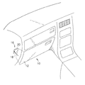
図1に示す車両のグローブボックス10等には、グローブボックス本体12が急激に開放されたり、開閉時に不快な衝撃音等が発生しないように、ダンパ機構が備えられており、車両本体側にはダンパユニット16を構成するケース20が配設され、グローブボックス本体12側にはダンパユニット16を構成するストリング18が固定されている。
【0028】
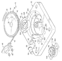
図2及び図3に示すように、ダンパユニット16には略矩形状のケース20が備えられており、車両本体に設けられた取付台座22に固定される(図4参照)。ケース20の中央部には収納凹部24が凹設されており、この収納凹部24の中心部にはボス26が突設している。
【0029】
ボス26は大径部26Aと小径部26Bとで構成されており、小径部26Bから大径部26Aの基部側に架けて軸方向に沿って二分する切込み部28が形成されている。この切込み部28にはゼンマイバネ30の中心側に位置する一端部32Aが嵌め込み可能となっており、大径部26Aの部分にゼンマイバネ30の一端部が固定され、大径部26Aの外周面を時計回り(矢印方向)に緩く複数回巻かれている。
【0030】
また、ボス26にはギア部32を備えたギア部材34が係合可能となっており、ギア部材34の軸芯部に、ボス26を構成する小径部26Bと係合可能な貫通穴36が形成されている。この貫通穴36が小径部26Bと係合された状態で、ギア部材34が収納凹部24内を回転自在に収納可能となる。
【0031】
ここで、収納凹部24の周縁部には、収納凹部24の内径寸法よりも拡径された環状の載置部24Aが形成されており、ギア部32が載置可能となっている。また、収納凹部24の内周面には、収納凹部24の底面から隙間t(図5参照)を設けて3個の爪部38が等間隔に配置されており、半径方向に沿って外側へ広がる方向へ弾性変形可能となっている。
【0032】
一方、貫通穴36の外側には、収納凹部24の内径寸法よりも小径の円筒状の芯体40が突設しており、芯体40の先端部からは、環状のフランジ部42がギア部32と平行に張り出している。また、フランジ部42の外径寸法は、収納凹部24の内径寸法よりも若干小さくなっており、フランジ部42の肉厚は、爪部38と収納凹部24の底面との間に設けられた隙間tよりも若干薄くなっている。
【0033】
このため、フランジ部42を収納凹部24の奥方へ挿入すると、爪部38が外側へ弾性変形し、フランジ部42が隙間t内に配置されると、爪部38が復元して、これにより、フランジ部42を介してギア部材34が抜け止めされると共に、ギア部材34の貫通穴36がボス26の小径部26Bと係合してギア部材34が収納凹部24内で回転可能に軸支される。
【0034】
また、ギア部材34の芯体40には、内周面から僅かに離間した位置に、ギア部32側からフランジ部42側に架けて係止片44が形成されており、収納凹部24の中心部に設けられたボス26に一端部32Aが固定されたゼンマイバネ30の他端部32Bが係止される。
【0035】
また、芯体40の外周面には、ストリング18の一端部が固定され、時計回り(矢印方向)に巻き付けられている。このストリング18を引き出すと、ギア部材34が時計回りに回転し、これにより、ゼンマイバネ30が巻締まることとなり、ゼンマイバネ30は縮径されて、ボス26の大径部26Aの外周面が巻締められ、弾性力が蓄積される。
【0036】
一方、ストリング18の他端部には、平板状の係止具46が固定されており、この係止具46の中央部には、小径穴48Aと大径穴48Bとが連続して形成された長穴部48が設けられている。
【0037】
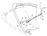
ここで、図4及び図5に示すように、小径穴48Aはグローブボックス本体12の側壁に設けられた係止部50に嵌合可能となっており、係止部50に大径穴48Bを挿通させた後、係止部50に沿って長穴部48を移動させ、係止部50を小径穴48Aに嵌合させる。
【0038】
これにより、係止具46がグローブボックス本体12の側壁に固定され、グローブボックス本体12を開放させると、係止具46を介してストリング18がケース20内から引き出されることとなる。
【0039】
ところで、図2に示すように、収納凹部24には半径方向に沿って収納部52が凹設されており、シリコンオイル等のオイルの粘性抵抗を利用してギア部56の回転力を制動する回転ダンパ54が収納可能となっている。
【0040】
収納部52の底面には、穴部52Aが形成されており、また、ケース20の裏面側には、穴部52Aを間に置いて、載置台(図示省略)が形成されている。回転ダンパ54に設けられた一対の固定片54Aを載置台に載置した状態で固定し、この固定片54Aを介して回転ダンパ54を収納部52内に配置する。このとき、回転ダンパ54は、回転ダンパ54を構成するギア部56がギア部材34のギア部32と噛み合う高さとされる。
【0041】
一方、穴部52Aの近傍に位置するケース20の外壁には、切欠き部58が形成されており、切欠き部58には一対の保持壁60が設けられている。この保持壁60には爪部62が形成されており、爪部62にはローラ部材64が係合し、これにより、ローラ部材64が保持壁60に固定される。
【0042】
また、穴部52Aは、ギア部材34の芯体40に巻き付けられたストリング18が通過可能となっており、穴部52Aを通過したストリング18がローラ部材64に巻掛けられる。
【0043】
次に、本発明の実施の形態に係るダンパユニットの作用について説明する。
【0044】
ラッチ機構などにより構成されたロック装置を解除し、図2、図4及び図5に示すように、グローブボックス本体12を開放させると、グローブボックス本体12は自重により、車両本体に配設されたガイドレール(図示省略)に案内されて開放され、図示しないストッパに当接して停止する。
【0045】
ここで、グローブボックス本体12の開放によって、グローブボックス本体12の側壁に係止された係止具46を介して、ストリング18がダンパユニット16を構成するケース20から引き出される。
【0046】
ストリング18はギア部材34の芯体40に固定され、芯体40の外周面に時計回りに巻き付けられているため、ストリング18の引出しにより、ギア部材34は時計回りに回転し、ギア部材34のギア部32と噛み合うギア部56が回転する。
【0047】
このように、ギア部材34のギア部32を介して回転ダンパ54のギア部56を回転させることで、回転ダンパ54による制動力が働き、ギア部材34の回転力は制動される。
【0048】
このため、ストリング18が勢い良く引き出されることはなく、換言すると、グローブボックス本体12は回転ダンパ54の制動力により、ゆっくりと開放されることとなり、グローブボックス10に対する高級感が得られる。
【0049】
また、ケース20の収納凹部24の中心部に突設されたボス26の回りを時計方向に巻き付けられたゼンマイバネ30は、ギア部材34が時計回りに回転することで、巻締められ、縮径してボス26の外周面を締め付ける。
【0050】
このように、ストリング18が引き出されるときに、ゼンマイバネ30がボス26の外周面を巻締めるため、ゼンマイバネ30とボス26の外周面との間で摺動抵抗が生じ、ギア部材34の回転力を制動することができ、ゼンマイバネ30によるダンパ効果を得ることができる。
【0051】
さらに、ギア部材34の軸芯部に貫通穴36を設け、収納凹部24の中央部に突設されたボス26の小径部26Bに係合させて、ギア部材34を回転可能に軸支させると共に、貫通穴36の外側に円筒状の芯体40を設け、この芯体40の外周面にストリング18を巻き付け、また、芯体40内でボス26の外周面にゼンマイバネ30を巻き付けるようにすることで、ギア部材34とストリング18とゼンマイバネ30とを同軸上に配置することができる。このため、ギア部材34とストリング18とゼンマイバネ30との間で軸芯のズレがなく、高い精度でダンパユニット16を組み立てることができる。
【0052】
また、芯体40を円筒状とし、芯体40の外周面にストリング18を巻き付けると共に、芯体40内でボス26の外周面にゼンマイバネ30を巻き付けるようにすることで、例えば、芯体40の外周面にストリング18及びゼンマイバネ30をそれぞれ巻き付けた場合と比較して、芯体40の長さを短くすることができる。このため、ダンパユニット16の肉厚を薄くすることができ、ダンパユニット16をコンパクトにすることができる。
【0053】
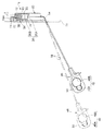
さらに、図3及び図5に示すように、ストリング18が通過する穴部52Aの近傍に位置するケース20の外壁に切欠き部58を形成し、切欠き部58内にローラ部材64を固定してストリング18を巻掛けることで、ストリング18がケース20から引き出されるときに、このローラ部材64を介してストリング18の方向転換を行うことができるため、ダンパユニット16の取付方向の自由度が大きくなる。
【0054】
また、図4に示すように、グローブボックス本体12は支点66を中心に回動するため、ストリング18をローラ部材64に巻掛けることで、グローブボックス本体12の開放をスムーズにすることができる。さらに、グローブボックス本体12の開放角度が大きくなるに従って、ストリング18がローラ部材64を巻き付ける巻付け角度が大きくなるため、摺動抵抗を大きくすることができ、ダンパ効果を得ることができる。
【0055】
さらに、図2に示すストリング18が引き出される方向にギア部材34が回転したとき、ギア部材34の回転に伴って、ゼンマイバネ30が巻締まり、縮径されるため、ボス26の外周面が巻締められ、弾性力が蓄積される。このため、グローブボックス本体12を閉止させるとき、ゼンマイバネ30の復元力によって、引き出されたストリング18をボス26に巻き付けることができる。
【0056】
ここで、回転ダンパ54をワンウェイダンパとし、ストリング18が引き出される方向にギア部材34が回転したときにギア部材34の回転力を制動するようにすることで、グローブボックス本体12を開放させるときは、ダンパ効果が得られ、これによって、ストリング18をゆっくり引き出させ、グローブボックス本体12をゆっくり開放させることができ、また、グローブボックス本体12を閉止させるときは、ダンパが効かないため、グローブボックス本体12の閉止方向への抵抗が少なくなり、グローブボックス本体12をさらに小さい力で閉止させることができる。
【0057】
なお、本形態では、車両本体側にダンパユニット16を構成するケース20を配設し、グローブボックス本体12側にダンパユニット16を構成するストリング18を固定したが、グローブボックス本体12側にケース20を配設し、車両本体側にストリング18を固定しても良い。
【0058】
また、本形態では、ギア部材34の芯体40を円筒状として芯体40内でボス26の外周面にゼンマイバネ30を巻き付けるようにしたが、芯体40の長さを長くして、芯体40の外周面にストリング18及びゼンマイバネ30をそれぞれ巻き付けても良いのは勿論のことである。さらに、ローラ部材64については、必ずしも必要とするものではなく、ギア部材34等の配置によっては不要となる場合もある。
【0059】
また、本形態では、グローブボックス本体12について説明したが、本発明はこれに限るものではなく、引出可能な部材を有するものであれば良く、また、引出し方向も回動移動だけでなく直線移動であっても良い。このため、車室内で用いられるカップホルダー、灰皿等であっても良い。
【0060】
【発明の効果】
本発明は、上記構成としたので、請求項1に記載の発明では、ギアとストリングとスプリングとを同軸上に配置することができるため、ギアとストリングとスプリングとの間で軸芯のズレがなく、ダンパユニットを高い精度で組み立てることができる。また、ストリングが引き出されるとき、ギアに噛み合っている回転ダンパによりギアの回転力は制動されるため、勢い良くストリングが引き出されることはない。さらに、ストリングが引き出される方向にギアが回転したとき、ギアの回転に伴ってスプリングには弾性力が蓄積されるため、引き出されたストリングを戻すときスプリングの復元力によってストリングを芯体に巻き付けることができる。
【0061】
請求項2に記載の発明では、ストリングが引き出されるときには、ワンウェイダンパが働き、ストリングはゆっくり引き出され、ストリングを戻すときには、ワンウェイダンパが働かないため、スムーズに戻すことができる。
【0062】
請求項3に記載の発明では、ダンパユニットの肉厚を薄くすることができ、ダンパユニットをコンパクトにすることができる。請求項4に記載の発明では、ストリングが引き出されるときに、ゼンマイバネには弾性力が蓄積され留と共に、ゼンマイバネがボスを巻締めることで、ゼンマイバネとボスの外周面との間で摺動抵抗が生じ、ゼンマイバネによるダンパ効果を得ることができる。
【0063】
請求項5に記載の発明では、ストリングがケースから引き出されるときに、ガイド部材を介してストリングの方向転換を行うことができるため、ダンパユニットの取付方向の自由度が大きくなる。
【0064】
請求項6に記載の発明では、支点を中心に回動する開閉部材にストリングの自由端部を固定した場合でも、該開閉部材の開放をスムーズにすることができる。また、開閉部材の開放角度が大きくなるに従って、ストリングがローラ部材を巻き付ける巻付け角度が大きくなるため、摺動抵抗を大きくすることができ、ストリング18によるダンパ効果を得ることができる。
【0065】
請求項7に記載の発明では、グローブボックスを開放させるときには、回転ダンパによる制動力が働き、グローブボックス本体はゆっくりと開放され、高級感が得られる。また、ワンウェイダンパを用い、グローブボックスを閉止させるときに回転ダンパによる制動力が働かないようにすることで、小さい力でグローブボックスを閉止させることができる。
【図面の簡単な説明】
【図1】本発明の実施の形態に係るダンパユニットが適用されたグローブボックスを示す説明図である。
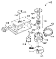
【図2】本発明の実施の形態に係るダンパユニットの分解斜視図である。
【図3】本発明の実施の形態に係るダンパユニットの平面図である。
【図4】本発明の実施の形態に係るダンパユニットが適用されたグローブボックスの動作を示す側断面図である。
【図5】本発明の実施の形態に係るダンパユニットの動作を示す部分断面図である。
【図6】従来のダンパユニット及びダンパユニットが適用された引出し体を斜視図である。
【図7】従来のダンパユニットを示す分解斜視図である。
【符号の説明】
10 グローブボックス(グローブボックス装置)
12 グローブボックス本体
16 ダンパユニット
18 ストリング
20 ケース
22 取付台座(車両本体)
26 ボス
30 ゼンマイバネ(スプリング)
34 ギア部材(ギア)
40 芯体
54 回転ダンパ
64 ローラ部材(ガイド部材)[0001]
TECHNICAL FIELD OF THE INVENTION
The present invention relates to a damper unit and a clove box device using the damper unit.
[0002]
[Prior art]
6 and 7, an automatic feeding device 102 (see, for example, Patent Document 1) of the
[0003]
In this
[0004]
As described above, when the take-
[0005]
On the other hand, when the
[0006]
Therefore, even if the take-
[0007]
In this state, the
[0008]
Next, when the revolving door is opened, the
[0009]
As a result, a rotational force for driving the take-
[0010]
On the other hand, when the take-
[0011]
Accordingly, the take-
[0012]
As described above, in the
[0013]
[Patent Document 1]
Japanese Utility Model Publication No. 4-46595 (page 6-11, FIG. 7)
[0014]
[Problems to be solved by the invention]
An object of the present invention is to provide an inexpensive damper unit with a simple configuration and a clove box device using the damper unit in consideration of the above facts.
[0015]
[Means for Solving the Problems]
According to the first aspect of the present invention, there is provided a gear in which a core is protruded from a shaft core portion and is rotatably housed in a case, a string wound around the core, and a rotational force of a gear meshing with the gear. It is characterized by having a rotary damper for braking, and a spring having one end fixed to the case and the other end fixed to the core body to store elasticity when the string is pulled out.
[0016]
According to the first aspect of the present invention, the gear, the string, and the spring are coaxially arranged by providing a core on the shaft core of the gear, winding the string around the core, and fixing the string. Can be. Therefore, there is no displacement of the shaft center between the gear, the string, and the spring, and the damper unit can be assembled with high accuracy.
[0017]
Also, when the string is pulled out, the gear around which the string is wound rotates. At this time, the rotating force of the gear is braked by the rotary damper meshing with the gear, so that the string is not pulled out vigorously.
[0018]
Furthermore, when the gear rotates in the direction in which the string is pulled out, elastic force is accumulated in the spring with the rotation of the gear. For this reason, when returning the pulled-out string, the string can be wound around the core by the restoring force of the spring.
[0019]
In the invention described in claim 2, the rotary damper is a one-way damper that brakes the rotational force of the gear when the gear rotates in the direction in which the string is pulled out. Thereby, when the string is pulled out, the one-way damper works, and when the string is pulled out, and when the string is returned, the one-way damper does not work, so that the string can be returned smoothly.
[0020]
According to the third aspect of the invention, the core body is a cylindrical portion, and the string is wound around the outer peripheral surface of the cylindrical portion. Further, one end of the spring is wound around a boss that is located inside the cylindrical portion and protrudes from the case, and the other end is fixed to the inner peripheral surface of the cylindrical portion.
[0021]
Thereby, for example, the length of the core can be shortened as compared with a case where the core is a cylindrical portion and the string and the spring are respectively wound around the outer peripheral surface of the column. For this reason, the thickness of the damper unit can be reduced, and the damper unit can be made compact.
[0022]
According to the invention described in claim 4, the spring is a spring, and when the string is pulled out, the cylindrical portion rotates and the spring wraps the boss. For this reason, when the string is pulled out, elastic force is accumulated in the mainspring and the spring is wound around the boss, thereby causing sliding resistance between the mainspring and the outer peripheral surface of the boss. Can be obtained.
[0023]
According to the invention described in claim 5, a guide member for guiding the string is provided at the outlet from which the string is drawn out of the case. Thus, when the string is pulled out of the case, the direction of the string can be changed via the guide member, so that the degree of freedom in the mounting direction of the damper unit is increased.
[0024]
In the invention described in claim 6, the guide member is a roller. Therefore, even when the free end of the string is fixed to the opening / closing member that rotates about the fulcrum, the opening of the opening / closing member can be made smooth. Further, as the opening angle of the opening / closing member increases, the winding angle at which the string winds the roller member increases, so that the sliding resistance can be increased and the damper effect of the
[0025]
In the invention according to claim 7, the damper unit according to any one of
[0026]
Thus, when the glove box is opened, the braking force by the rotary damper works, and the glove box body is slowly opened, giving a sense of quality. Further, the glove box can be closed with a small force by using a one-way damper so that the braking force by the rotary damper does not work when the glove box is closed.
[0027]
BEST MODE FOR CARRYING OUT THE INVENTION
The
[0028]
As shown in FIGS. 2 and 3, the
[0029]
The
[0030]
A
[0031]
Here, an annular mounting
[0032]
On the other hand, a
[0033]
For this reason, when the
[0034]
A locking
[0035]
One end of the
[0036]
On the other hand, a flat-shaped
[0037]
Here, as shown in FIGS. 4 and 5, the small-
[0038]
Thereby, the locking
[0039]
By the way, as shown in FIG. 2, a
[0040]
A
[0041]
On the other hand, a
[0042]
Further, the
[0043]
Next, the operation of the damper unit according to the embodiment of the present invention will be described.
[0044]
When the lock device constituted by the latch mechanism or the like is released and the
[0045]
Here, when the glove box
[0046]
Since the
[0047]
As described above, by rotating the
[0048]
For this reason, the
[0049]
The
[0050]
In this manner, when the
[0051]
Further, a through
[0052]
Further, by forming the
[0053]
Further, as shown in FIGS. 3 and 5, a
[0054]
Further, as shown in FIG. 4, since the glove box
[0055]
Furthermore, when the
[0056]
Here, when the
[0057]
In this embodiment, the
[0058]
In the present embodiment, the
[0059]
In this embodiment, the glove box
[0060]
【The invention's effect】
Since the present invention is configured as described above, according to the first aspect of the present invention, the gear, the string, and the spring can be arranged coaxially. Therefore, the damper unit can be assembled with high accuracy. Further, when the string is pulled out, the rotating force of the gear is braked by the rotary damper meshing with the gear, so that the string is not pulled out vigorously. Furthermore, when the gear rotates in the direction in which the string is pulled out, the elastic force is accumulated in the spring with the rotation of the gear, so when returning the drawn string, the string is wound around the core by the restoring force of the spring. Can be.
[0061]
According to the second aspect of the invention, when the string is pulled out, the one-way damper works, and when the string is pulled out, and when the string is returned, the one-way damper does not work. Therefore, the string can be returned smoothly.
[0062]
According to the third aspect of the invention, the thickness of the damper unit can be reduced, and the damper unit can be made compact. According to the fourth aspect of the present invention, when the string is pulled out, the elastic force is accumulated in the spring and the spring is wound around the boss, so that the sliding resistance between the spring and the outer peripheral surface of the boss is reduced. As a result, a damper effect by the mainspring can be obtained.
[0063]
According to the fifth aspect of the present invention, when the string is pulled out of the case, the direction of the string can be changed via the guide member, so that the degree of freedom in the mounting direction of the damper unit is increased.
[0064]
According to the sixth aspect of the invention, even when the free end of the string is fixed to the opening / closing member that rotates about the fulcrum, the opening of the opening / closing member can be made smooth. Further, as the opening angle of the opening / closing member increases, the winding angle at which the string winds the roller member increases, so that the sliding resistance can be increased and the damper effect of the
[0065]
According to the seventh aspect of the present invention, when the glove box is opened, the braking force by the rotary damper works, and the glove box body is slowly opened to provide a sense of quality. Further, the glove box can be closed with a small force by using a one-way damper so that the braking force by the rotary damper does not work when the glove box is closed.
[Brief description of the drawings]
FIG. 1 is an explanatory diagram showing a glove box to which a damper unit according to an embodiment of the present invention is applied.
FIG. 2 is an exploded perspective view of the damper unit according to the embodiment of the present invention.
FIG. 3 is a plan view of the damper unit according to the embodiment of the present invention.
FIG. 4 is a side sectional view showing an operation of the glove box to which the damper unit according to the embodiment of the present invention is applied.
FIG. 5 is a partial cross-sectional view illustrating an operation of the damper unit according to the embodiment of the present invention.
FIG. 6 is a perspective view of a conventional damper unit and a drawer to which the damper unit is applied.
FIG. 7 is an exploded perspective view showing a conventional damper unit.
[Explanation of symbols]
10 Glove box (glove box device)
12
26
34 Gear member (gear)
40
Claims (7)
前記芯体に巻き付けられたストリングと、
前記ギアと噛み合いギアの回転力を制動する回転ダンパと、
一端部が前記ケースに固定され、他端部が前記芯体に固定されて、前記ストリングが引き出されるとき弾性力が蓄積されるスプリングと、
を有することを特徴とするダンパユニット。A gear with a core protruding from the shaft core and rotatably housed in the case;
A string wound around the core,
A rotational damper for braking the rotational force of the gear meshing with the gear;
A spring having one end fixed to the case, the other end fixed to the core, and an elastic force accumulated when the string is pulled out;
A damper unit comprising:
Priority Applications (3)
| Application Number | Priority Date | Filing Date | Title |
|---|---|---|---|
| JP2002340904A JP2004175151A (en) | 2002-11-25 | 2002-11-25 | Damper unit and glove box device using this damper unit |
| US10/667,437 US6857675B2 (en) | 2002-11-25 | 2003-09-23 | Damper unit and glove box device using the same |
| GB0323012A GB2395541A (en) | 2002-11-25 | 2003-10-02 | Damper unit and glove box device using the same |
Applications Claiming Priority (1)
| Application Number | Priority Date | Filing Date | Title |
|---|---|---|---|
| JP2002340904A JP2004175151A (en) | 2002-11-25 | 2002-11-25 | Damper unit and glove box device using this damper unit |
Publications (1)
| Publication Number | Publication Date |
|---|---|
| JP2004175151A true JP2004175151A (en) | 2004-06-24 |
Family
ID=29417299
Family Applications (1)
| Application Number | Title | Priority Date | Filing Date |
|---|---|---|---|
| JP2002340904A Pending JP2004175151A (en) | 2002-11-25 | 2002-11-25 | Damper unit and glove box device using this damper unit |
Country Status (3)
| Country | Link |
|---|---|
| US (1) | US6857675B2 (en) |
| JP (1) | JP2004175151A (en) |
| GB (1) | GB2395541A (en) |
Cited By (6)
| Publication number | Priority date | Publication date | Assignee | Title |
|---|---|---|---|---|
| JP2006014804A (en) * | 2004-06-30 | 2006-01-19 | Nemoto Kyorindo:Kk | Member holding mechanism |
| KR100610375B1 (en) | 2005-03-15 | 2006-08-09 | 쌍용자동차 주식회사 | Opening and closing device of glovebox for automobile |
| KR100613237B1 (en) | 2005-05-16 | 2006-08-22 | 현대모비스 주식회사 | Glove box for automobile |
| KR100643459B1 (en) * | 2004-08-04 | 2006-11-10 | 가부시키가이샤 니프코 | Damper device |
| JP2008100012A (en) * | 2006-10-23 | 2008-05-01 | Nippon Akyuraido Kk | Slide rail |
| JP2016205067A (en) * | 2015-04-28 | 2016-12-08 | 有限会社ベスト青梅 | Tension imparting device |
Families Citing this family (23)
| Publication number | Priority date | Publication date | Assignee | Title |
|---|---|---|---|---|
| US7152718B2 (en) * | 2002-04-16 | 2006-12-26 | Illinois Tool Works Inc | Damper |
| DE10228399A1 (en) * | 2002-06-25 | 2004-01-15 | Daimlerchrysler Ag | Storage compartment for a vehicle |
| DE602004000597D1 (en) * | 2003-07-31 | 2006-05-18 | Nifco Inc | damping device |
| CN100339549C (en) * | 2004-02-20 | 2007-09-26 | 株式会社利富高 | Cover opening and closing mechanism |
| JP4240478B2 (en) * | 2004-03-31 | 2009-03-18 | 株式会社パイオラックス | Vehicle storage device |
| KR100565372B1 (en) * | 2004-06-09 | 2006-03-30 | 현대모비스 주식회사 | Damping system of a glove box |
| DE102005013742A1 (en) * | 2004-10-29 | 2006-05-04 | Dura Automotive Systems Gmbh | Device for the synchronous extension and retraction of two wire sections |
| US7163248B2 (en) * | 2004-11-08 | 2007-01-16 | Lear Corporation | Automotive console with adjustable armrest |
| US7240941B2 (en) * | 2004-11-08 | 2007-07-10 | Lear Corporation | Vehicle storage assembly with adjustable door |
| US7192072B2 (en) * | 2005-02-18 | 2007-03-20 | Lear Corporation | Movable panel assembly |
| JP4398891B2 (en) * | 2005-03-15 | 2010-01-13 | 本田技研工業株式会社 | Glove box for vehicle |
| JP4251498B2 (en) * | 2005-06-03 | 2009-04-08 | 豊田合成株式会社 | Lid device |
| US7621419B2 (en) * | 2005-08-05 | 2009-11-24 | Nifco Inc. | Door operating mechanism and unit |
| US20070108676A1 (en) * | 2005-11-14 | 2007-05-17 | Zeilenga Chad K | Viscous strand damper assembly |
| CZ302307B6 (en) * | 2007-05-17 | 2011-02-16 | Magna Exteriors & Interiors (Bohemia) S.R.O. | Brake of glove compartment cover |
| DE102008006102B4 (en) * | 2008-01-25 | 2018-11-08 | Dr. Ing. H.C. F. Porsche Aktiengesellschaft | Container for installation in the interior of a motor vehicle |
| CN102112777B (en) * | 2008-08-07 | 2014-12-03 | 伊利诺斯工具制品有限公司 | Viscous strand damper assembly |
| US9132751B2 (en) * | 2012-07-26 | 2015-09-15 | Leggett & Platt Canada Co. | Remote damping system |
| DE102013203331A1 (en) * | 2013-02-28 | 2014-08-28 | Zf Friedrichshafen Ag | Rotary damper for a vehicle |
| CN109070808B (en) * | 2016-03-01 | 2022-06-07 | 上海延锋金桥汽车饰件系统有限公司 | Storage compartment for a vehicle interior |
| US9850695B2 (en) * | 2016-03-14 | 2017-12-26 | Ford Global Technologies Llc | Door restraint mechanism |
| US10066431B2 (en) * | 2016-03-30 | 2018-09-04 | Ford Global Technologies Llc | Bellows spring damper |
| CN106917839B (en) * | 2017-04-18 | 2022-09-09 | 沈阳工程学院 | Mechanical damper for nuclear power |
Family Cites Families (9)
| Publication number | Priority date | Publication date | Assignee | Title |
|---|---|---|---|---|
| JPH023656Y2 (en) * | 1984-10-23 | 1990-01-29 | ||
| JP2557064Y2 (en) * | 1992-03-25 | 1997-12-08 | 株式会社パイオラックス | Structure of damper device such as storage box |
| JP3451518B2 (en) | 1996-05-29 | 2003-09-29 | 関東自動車工業株式会社 | Reel type door opening / closing mechanism of grab box |
| US6185868B1 (en) * | 1996-09-26 | 2001-02-13 | Toyota Shatai Kabushiki Kaisha | Automatic closer of pop-up door of vehicle |
| US5809697A (en) * | 1997-02-07 | 1998-09-22 | Chen; Wen Hua | Door closer |
| US6062623A (en) * | 1998-05-18 | 2000-05-16 | Prince Corporation | Latch for vehicle overhead storage bin |
| US6523788B2 (en) * | 2001-04-09 | 2003-02-25 | Dennis R. Zander | Model railroad crossing gate |
| JP3833925B2 (en) * | 2001-10-29 | 2006-10-18 | 株式会社ニフコ | Door body opening / closing mechanism and opening / closing device using the same |
| KR100447568B1 (en) * | 2002-09-13 | 2004-09-04 | 현대모비스 주식회사 | Glove box damper system |
-
2002
- 2002-11-25 JP JP2002340904A patent/JP2004175151A/en active Pending
-
2003
- 2003-09-23 US US10/667,437 patent/US6857675B2/en not_active Expired - Fee Related
- 2003-10-02 GB GB0323012A patent/GB2395541A/en not_active Withdrawn
Cited By (6)
| Publication number | Priority date | Publication date | Assignee | Title |
|---|---|---|---|---|
| JP2006014804A (en) * | 2004-06-30 | 2006-01-19 | Nemoto Kyorindo:Kk | Member holding mechanism |
| KR100643459B1 (en) * | 2004-08-04 | 2006-11-10 | 가부시키가이샤 니프코 | Damper device |
| KR100610375B1 (en) | 2005-03-15 | 2006-08-09 | 쌍용자동차 주식회사 | Opening and closing device of glovebox for automobile |
| KR100613237B1 (en) | 2005-05-16 | 2006-08-22 | 현대모비스 주식회사 | Glove box for automobile |
| JP2008100012A (en) * | 2006-10-23 | 2008-05-01 | Nippon Akyuraido Kk | Slide rail |
| JP2016205067A (en) * | 2015-04-28 | 2016-12-08 | 有限会社ベスト青梅 | Tension imparting device |
Also Published As
| Publication number | Publication date |
|---|---|
| US20040189035A1 (en) | 2004-09-30 |
| GB2395541A (en) | 2004-05-26 |
| GB0323012D0 (en) | 2003-11-05 |
| US6857675B2 (en) | 2005-02-22 |
Similar Documents
| Publication | Publication Date | Title |
|---|---|---|
| JP2004175151A (en) | Damper unit and glove box device using this damper unit | |
| US7201130B2 (en) | Recoil starter | |
| JP6321537B2 (en) | Film transfer tool | |
| US6901899B2 (en) | Recoil starter | |
| JP2008024284A (en) | Webbing take-up device | |
| WO2011070935A1 (en) | Transfer device | |
| JP4381280B2 (en) | Recoil starter | |
| WO2011070934A1 (en) | Transfer tool | |
| JP5331048B2 (en) | Webbing take-up device | |
| JP4641632B2 (en) | Roll screen | |
| JP6509530B2 (en) | Recoil starter | |
| JP5529076B2 (en) | Webbing take-up device | |
| KR101819933B1 (en) | Cord Reel Assembly of Vacuum Cleaner with Deceleration Function | |
| JP3818953B2 (en) | Sheet winding device | |
| JP2007327911A (en) | Tape measure | |
| JP3480026B2 (en) | Window opening and closing device | |
| JP3513723B2 (en) | Reel with return prevention mechanism | |
| JP5872308B2 (en) | Webbing take-up device | |
| JPH05176662A (en) | Clutch mechanism of reel for fishing | |
| JP2022181753A (en) | recoil starter | |
| JP5448891B2 (en) | Webbing take-up device | |
| JPH0571067U (en) | Tension reducer | |
| JP3795641B2 (en) | Webbing take-up device | |
| JP2007051509A (en) | Closer for sliding door | |
| JP2007171130A (en) | Tape measure |
Legal Events
| Date | Code | Title | Description |
|---|---|---|---|
| A521 | Request for written amendment filed |
Free format text: JAPANESE INTERMEDIATE CODE: A821 Effective date: 20050330 |
|
| A621 | Written request for application examination |
Free format text: JAPANESE INTERMEDIATE CODE: A621 Effective date: 20050330 |
|
| A711 | Notification of change in applicant |
Free format text: JAPANESE INTERMEDIATE CODE: A711 Effective date: 20050330 |
|
| A521 | Request for written amendment filed |
Free format text: JAPANESE INTERMEDIATE CODE: A821 Effective date: 20050330 |
|
| A131 | Notification of reasons for refusal |
Free format text: JAPANESE INTERMEDIATE CODE: A131 Effective date: 20061017 |
|
| A977 | Report on retrieval |
Free format text: JAPANESE INTERMEDIATE CODE: A971007 Effective date: 20061020 |
|
| A02 | Decision of refusal |
Free format text: JAPANESE INTERMEDIATE CODE: A02 Effective date: 20070403 |