WO2010103618A1 - 紙幣結束装置及び紙幣結束方法 - Google Patents
紙幣結束装置及び紙幣結束方法 Download PDFInfo
- Publication number
- WO2010103618A1 WO2010103618A1 PCT/JP2009/054558 JP2009054558W WO2010103618A1 WO 2010103618 A1 WO2010103618 A1 WO 2010103618A1 JP 2009054558 W JP2009054558 W JP 2009054558W WO 2010103618 A1 WO2010103618 A1 WO 2010103618A1
- Authority
- WO
- WIPO (PCT)
- Prior art keywords
- binding
- banknote
- stamp
- unit
- bundled
- Prior art date
- Legal status (The legal status is an assumption and is not a legal conclusion. Google has not performed a legal analysis and makes no representation as to the accuracy of the status listed.)
- Ceased
Links
Images









Classifications
-
- G—PHYSICS
- G07—CHECKING-DEVICES
- G07D—HANDLING OF COINS OR VALUABLE PAPERS, e.g. TESTING, SORTING BY DENOMINATIONS, COUNTING, DISPENSING, CHANGING OR DEPOSITING
- G07D11/00—Devices accepting coins; Devices accepting, dispensing, sorting or counting valuable papers
- G07D11/10—Mechanical details
- G07D11/16—Handling of valuable papers
Definitions
- the present invention relates to, for example, a banknote binding apparatus and a banknote binding method for binding banknotes of a specific denomination in units of a predetermined number.
- a stamp that stamps a stamp on a binding section that binds a predetermined number of banknotes to be bound with a binding band, and a binding band that is arranged on the front or back surface of the binding banknotes that are bound by the binding section.
- a technique having a stamp portion is known (see, for example, Patent Documents 1 and 2).
- Patent Document 1 since the stamp mark of the bank name is stamped on the binding band arranged on the front or back surface of the bundled banknotes bound at the binding section, the user creates the bundled banknotes with the stamp mark on the binding band. You can see the bank name.
- Patent Document 2 since a stamp mark such as a lossy ticket is stamped on a binding band disposed on the front surface or the back surface of a bundled banknote bundled at a binding section, the user can make a loss with the stamp mark on the binding band. It can be visually recognized as a bundled banknote of a ticket.
- the stamp mark is stamped on the binding band arranged on the front surface or the back surface of the bundled banknotes bound at the binding section, for example, a plurality of bundled banknotes in the banknote surface direction.
- the stamp mark stamped on the front or back surface of the bundled banknote cannot be visually recognized.
- the present invention has been made in view of the above points.
- the purpose of the present invention is to make it possible to visually recognize a stamp mark from the side of a bundled banknote even when a plurality of bundled banknotes are stacked in the banknote surface direction. It is in providing a binding apparatus and a banknote binding method.
- the banknote binding apparatus of the present invention includes a binding unit that creates a binding banknote by binding the binding target banknotes with a binding band, and a binding band of the binding banknote created by the binding part.
- a banknote bundling device having a stamp stamping part for stamping a stamp mark on the binding band so that a stamp mark is positioned, wherein the binding band is disposed on a side surface of the binding banknote in the binding band of the binding banknote. It is a requirement to have a stamp drive control unit that drives and controls the stamp stamp unit so as to stamp the stamp mark on the binding band so that the stamp mark is located on the top.
- the banknote binding apparatus of this invention has a bundle conveyance part which conveys the said bundled banknote produced in the said binding part in the discharge
- the said stamp drive control part is the said bundle conveyance part
- the stamp stamping part is moved and arranged on the transport path so that the stamp mark is positioned on the binding band on the side of the bundled banknote being transported on the transport path for transporting the bound banknote at In order to stamp the stamp mark on the top, it is necessary to drive and control the stamp stamp section.
- the banknote binding apparatus of the present invention is characterized in that, in the configuration of the invention described above, the bundle conveyance unit conveys the bundled banknote by gripping a short side end portion of the bundled banknote.
- the banknote binding apparatus of this invention is the structure of the said invention, WHEREIN:
- the said binding part winds the said binding object banknote in a banknote short direction in the state which wound the said binding band in the binding position of a predetermined number of binding object banknotes.
- the banknote binding apparatus of this invention is the structure of the said invention.
- WHEREIN The said binding part tightens the said binding band wound around the binding position of a predetermined number of binding object banknotes, and on the said binding band of the said binding banknote side surface. It is a requirement that the stamp stamping unit be driven and controlled so as to stamp the stamp mark on the banknote surface of the banknote to be bound in a state before the binding band is tightened so that the stamp mark is positioned at a position.
- the banknote binding apparatus of this invention is the structure of the said invention,
- the said stamp stamp part stamps a 1st stamp mark on the said binding band arrange
- the first stamp mark is positioned on the binding band disposed on the one side surface of the bundled banknote, and the second stamp mark is positioned on the binding band disposed on the other side surface of the bundled banknote.
- it is necessary to drive and control the first stamp stamp portion and the second stamp stamp portion so as to stamp the first stamp mark and the second stamp mark on the binding band.
- the banknote binding method of this invention is the banknote binding step which produces a binding banknote by binding a binding object banknote with a binding band, and the said binding banknote produced by the said banknote binding step.
- a stamp stamping step for stamping a stamp mark on the binding band so that the stamp mark is positioned on the binding band, wherein the stamp stamping step includes the binding band of the binding banknote, The stamp mark is stamped on the binding band so that the stamp mark is positioned on the binding band disposed on the side surface of the binding banknote.
- the stamp mark is stamped on the binding band so that the stamp mark is positioned on the binding band disposed on the side of the binding banknote among the binding bands of the binding banknote. Since it did in this way, even if a user piles up several bundled banknotes in the banknote surface direction, there exists an effect that a stamp mark can be visually recognized from the side of a bundled banknote.
- the banknote binding apparatus of this invention in addition to the effect of said invention, it conveys so that a stamp mark may be located on the binding band of the side of the bundled banknote currently conveyed on the conveyance path which conveys a bundled banknote in a discharge direction. Since the stamp stamping part is moved and arranged on the street so that the stamp mark is stamped on the binding band, even if the user stacks a plurality of bundled banknotes in the banknote surface direction, the user can stamp the stamp mark from the side of the binding banknotes. The effect that it can visually recognize is produced.
- the short side edge of the bundled banknote is gripped to transport the bundled banknote, so the long side edge that is the side of the bundled banknote This produces an effect that a stamp can be stamped from.
- the banknote binding apparatus of this invention in addition to the effect of the said invention, in the state which wound the binding band around the binding position of the predetermined number of binding target banknotes, it moves a binding target banknote in the banknote short direction. Since the stamp mark is placed on the banknote surface of the binding target banknote in a state where the binding band before the binding target banknote movement is wound so that the stamp mark is positioned on the binding band side of the binding banknote, the user Even if a plurality of bundled banknotes are stacked in the banknote surface direction, the stamp mark can be visually recognized from the side surface of the bundled banknotes.
- the binding band wound around the binding position of a predetermined number of banknotes to be bound is tightened, and the stamp mark is positioned on the binding band on the side of the binding banknote.
- the banknote binding apparatus of this invention in addition to the effect of said invention, while the 1st stamp mark is located on the binding band arrange
- the stamp mark is placed on the binding band so that the stamp mark is positioned on the binding band disposed on the side of the binding banknote in the binding band of the binding banknote. Since the stamping is performed, the user can visually recognize the stamp mark from the side surface of the bundled banknote even when the bundled banknotes are stacked in the banknote surface direction.
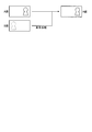
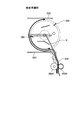
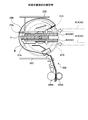
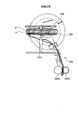
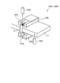
- FIG. 1 is a perspective view briefly showing an external configuration of the banknote sorting and binding processing apparatus according to the first embodiment.
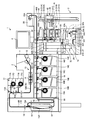
- FIG. 2 is an explanatory diagram showing a schematic configuration inside the banknote classification and binding processing device.
- FIG. 3 is an explanatory view briefly showing the reversing process of the banknote reversing unit.
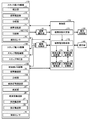
- FIG. 4 is a block diagram showing a schematic configuration inside the banknote classification and binding processing device.
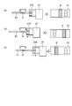
- FIG. 5 is an explanatory diagram briefly showing the operation transition of the pre-bundling transport unit.
- FIG. 6 is an explanatory diagram briefly showing the operation transition of the gripping and conveying unit.
- FIG. 7 is an explanatory view briefly showing the operation of the gripping and conveying unit on the bundling stage.
- FIG. 1 is a perspective view briefly showing an external configuration of the banknote sorting and binding processing apparatus according to the first embodiment.
- FIG. 2 is an explanatory diagram showing a schematic configuration inside the banknote classification and binding processing device.
- FIG. 3 is an
- FIG. 8 is an explanatory view briefly showing the operation transition of the stamp-side mechanical mechanism.
- FIG. 9 is an explanatory view briefly showing the operation transition of the discharge transport unit.
- FIG. 10 is a flowchart illustrating the processing operation of the control unit related to the first banknote bundling process of the first embodiment.
- FIG. 11 is an explanatory diagram that briefly shows the operating state of the bundling unit involved in bundling preparation.
- FIG. 12 is an explanatory diagram that briefly shows the operating state of the binding unit involved in setting the binding target banknotes.
- FIG. 13 is an explanatory view briefly showing the operating state of the binding unit when the pre-bundling transport unit is detached.
- FIG. 14 is an explanatory view briefly showing the operating state of the binding portion involved during temporary fastening.
- FIG. 15 is an explanatory view briefly showing the operating state of the binding portion involved in the final tightening.
- FIG. 16 is an explanatory view briefly showing the operating state of the binding portion involved during tightening.
- FIG. 17 is a flowchart illustrating the processing operation of the control unit related to the bundled banknote stamp stamping process according to the first embodiment.
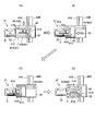
- FIG. 18 is an explanatory diagram illustrating a schematic configuration of a stamp-side mechanical mechanism according to the second embodiment.
- FIG. 19 is an explanatory diagram briefly showing the operation transition of the stamp side mechanical mechanism according to the second embodiment.
- FIG. 20 is a flowchart showing the processing operation of the control unit related to the second banknote bundling process.
- FIG. 21 is an explanatory diagram briefly showing the operation transition of the stamp side mechanical mechanism according to the third embodiment.
- FIG. 22 is a flowchart showing the processing operation of the control unit related to the third banknote bundling process.
- summary will be produced in the bundling part which produces a bundling banknote by bundling 100 bundling object banknotes with a bundling band, and a bundling part, for example.
- a banknote binding apparatus having a stamp stamping unit for stamping a stamp mark on a binding band so that the stamp mark is positioned on the binding band of the binding banknote, and disposed on a side of the binding banknote in the binding band of the binding banknote
- the stamp driving control unit that drives and controls the stamp stamping part is provided so that the stamp mark is positioned on the binding band.
- the stamp mark is stamped on the binding band so that the stamp mark is positioned on the binding band arranged on the side of the binding banknote in the binding band of the binding banknote. Even if a plurality of bundled banknotes are stacked in the banknote surface direction, the stamp mark can be visually recognized from the side surface of the bundled banknotes.
- FIG. 1 is a perspective view briefly showing the external configuration of the banknote classification and binding processing device of Example 1
- FIG. 2 is an explanatory diagram showing the schematic configuration inside the banknote classification and binding processing device.
- the banknote classification and binding processing apparatus 1 continuously deposits transaction banknotes, classifies and accumulates these deposited banknotes for each banknote type, and counts the number of banknotes deposited for each banknote type, and the banknote processing apparatus.
- 2 includes a banknote binding apparatus 3 that binds banknotes of the specific denomination classified in 2 in units of a predetermined number, for example, 100 sheets, and a display apparatus 4 that displays various information such as counting results.
- the banknote handling apparatus 2 transports the banknotes fed out by the hopper unit 11 that feeds transaction banknotes into the apparatus, the feeding unit 12 that feeds the banknotes fed into the hopper unit 11 in units of one sheet, and the feeding unit 12.
- the banknote transport unit 13 such as a transport belt
- the banknote identification unit 14 for identifying the type of the banknote transported by the banknote transport unit 13, and the banknote type of the banknote identification unit 14, for example, the front and back information
- the banknote reversing unit 15 reverses the banknote so that the conveyed banknote is directed to any one of the front and back surfaces.
- the banknote processing apparatus 2 rejects the banknote which does not correspond to the banknote classification corresponding to the stacker 16 and the banknote binding apparatus 3 which sorts and accumulates the banknotes conveyed by the banknote transport unit 13 according to the banknote type. And two first reject parts 17.
- the stacker 16 and the first reject unit 17 are provided with an impeller 16E (17C) that stacks the transported banknotes one by one at a predetermined position in the banknote stacking space.
- the four stackers 16 classify and accumulate the transported banknotes for each banknote type being set, and are configured by a first stacker 16A, a second stacker 16B, a third stacker 16C, and a fourth stacker 16D.
- a first stacker 16A for example, in the case of euro banknotes, in addition to the seven denominations of 5 euros, 10 euros, 20 euros, 50 euros, 100 euros, 200 euros and 500 euros, genuine and counterfeit
- the banknote binding apparatus 3 arranges three steps
- the three stacking stacking units 21 for sorting and stacking the specific denomination banknotes, and a predetermined number of banknotes to be bound to be sorted and stacked in the stacking stacking unit 21 are arranged below these three binding stacking units 21. For example, when it reaches 100 sheets, it has the binding part 22 which binds the 100 binding object banknotes with a binding band.
- the banknote binding apparatus 3 is disposed in the vicinity of the hopper unit 11, and is disposed in the vicinity of the banknotes bound by the binding unit 22, that is, the bundle discharge port 23 that discharges the banknotes to the operator side and the binding stacking unit 21.
- the bundling stacking unit 21 at the end of the transaction has a fraction return port 24 for discharging the bills being stacked to the operator side.
- the banknote binding device 3 also includes a pre-bundling transport unit 25 that grips and transports the binding target banknotes that are being accumulated in the binding stacking unit 21 to the binding unit 22 or the fraction return port 24, and the binding target banknotes in the binding unit 22.
- a post-bundling transport unit 26 that grips and transports the paper in the longitudinal direction and transports the bundled banknotes bundled in the bundling unit 22 to the bundle discharge port 23.
- the pre-bundling transport unit 25 grips the long side of 100 binding target banknotes among the binding target banknotes being stacked in the binding stacking unit 21, and binds these 100 binding target banknotes in the binding unit 22.
- the bills to be bundled in the bundling stacking unit 21 are gripped with less than 100 bills being stacked, and these bills are returned to the fraction return port 24 at the end of the transaction.
- the bundling stage 22 ⁇ / b> A of the bundling unit 22 corresponds to a bundling work area of the bundling unit 22.
- the post-bundling transport unit 26 transports the banknotes to be bound onto the binding stage 22A in the binding unit 22 by the pre-bundling transport unit 25, and then grips and grips the short side of the transported banknotes to be bound. While adjusting the movement of the banknotes to be bound in the longitudinal direction of the banknotes, the gripping and transporting part 27 gripping and transporting the bound banknotes bound by the binding part 22, and the bundled banknotes gripped and transported by the gripping and transporting part 27 to the bundle discharge port 23. And a discharge conveyance unit 28 for conveyance.
- the gripping and transporting unit 27 is configured to grip the short side of the banknotes to be bound at the work preparation position after transporting to the work preparation position on the binding stage 22A in the binding unit 22 by the transporting unit 25 before binding (described later). (See FIG. 6C). Note that the pre-bundling transport unit 25 opens the grip on the long side of the banknotes to be bound in accordance with the gripping operation on the short side of the banknotes to be bound by the gripping transport unit 27.
- the work preparation position corresponds to a position where movement adjustment of the binding target banknote relative to the binding work position on the binding stage 22A for performing the binding work, that is, a position where movement in the binding target banknote longitudinal direction is started.
- the bundling work position corresponds to a work position for bundling a bundling band on a bundling target banknote.
- the binding target banknote When the gripping and transporting unit 27 grips the binding target banknote at the work preparation position on the binding stage 22A of the binding unit 22, the binding target banknote is positioned so that the binding position of the binding target banknote is positioned at the binding work position on the binding stage 22A. Is adjusted in the longitudinal direction of the banknotes to be bound (see FIG. 6E described later).
- the binding part 22 can wind a binding band around the binding position of the binding target banknote by arranging the binding position of the binding target banknote at the binding work position.
- the gripping conveyance unit 27 moves the binding banknote to the work preparation position. Then, the bundled banknotes are conveyed into the discharge conveyance unit 28.
- the discharge transport unit 28 includes a bundled banknote lift unit 61 that transports the bundled banknotes gripped and transported by the gripper transport unit 27 to the upper part of the banknote binding unit 3, and a bundle transported to the upper part of the banknote binding unit 3 by the bundled banknote lift unit 61.
- the banknote classification and binding processing device 1 is connected to the hopper unit 11, connected to the first transport path 18 ⁇ / b> A and the first transport path 18 ⁇ / b> A disposed above the stacker 16, and arranged so as to be folded back in the stacking direction of the stacker 16.
- the bill transport path 18 includes the second transport path 18B and the second transport path 18B, and includes the third transport path 18C connected to the stacker 16 and the bundling stacking unit 21.
- the banknote identification part 14 shall be arrange
- the 2nd conveyance path 18B comprises a detachable unit connected to the 1st conveyance path 18A of the banknote classification binding processing apparatus 1 and the 3rd conveyance path 18C.
- the detection sensors 19 which detect an approach and passage of conveyance banknotes, such as a branch location on a conveyance path, a junction location, and the connection location between apparatuses, are each arrange
- the second reject unit 20 is disposed at the final end of the third conveyance path 18C.
- the second reject unit 20 is provided with a betting belt 20A for stacking transported banknotes in units of one sheet at a predetermined position in the banknote stacking space.
- FIG. A branching portion 13A that distributes to the rejecting portion 20 is arranged.
- the branching section 13A sorts the transported banknotes by driving a solenoid (not shown) when the leading edge of the transported banknotes is detected through the detection sensor 19.
- the banknote reversing unit 15 distributes the reversing route or the non-reversing route at the branching unit 13A provided in front of the banknote reversing unit 15 based on the front and back information which is the banknote type of the banknote identifying unit 14, In addition, it is transported to the third transport path 18C in alignment with a specific surface.
- the reversing member 15A having a curved surface extending in the banknote conveying direction, and a part of the reversing member 15A are hung obliquely with respect to the longitudinal direction of the reversing member 15A so as to be along the curved surface of the reversing member 15A.
- the banknote reversing unit 15 when a banknote is transported in a state where the transporting belt is driven by the drive motor, the banknote is sandwiched between the transporting belt and the reversing member 15 ⁇ / b> A and follows the movement of the transporting belt in the transporting direction. To move on. At this time, since the conveyor belt is hung on the curved surface so as to be oblique to the longitudinal direction of the reversing member 15A, the banknote is conveyed while being wound around the curved surface, and is reversed while being rotated. become. In addition, when the front and back are reversed, the surface of the bill is slid and guided by the guide portion, so that the bill can be reliably reversed while regulating the movement of the bill in the middle of conveyance.
- FIG. 3 is an explanatory view briefly showing the reversing process of the banknote reversing unit 15.
- the banknote reversing unit 15 transports the transported banknote to the third transport path 18 ⁇ / b> C while keeping the A surface (front surface) as the A surface (front surface), the A surface (surface) ),
- the transported banknote is transported to the third transport path 18C.
- the longitudinal reversal process of the banknote reversing unit 15 is performed through the reversal route. Is executed, the B side (rear surface) is reversed to the A side (front surface), and the conveyed banknote is conveyed to the third conveying path 18C.
- the hand unit 41 (see FIG. 2) of the pre-bundling transport unit 25 to enter the stacking space 31 are formed.
- the hand 41 that has entered through the notch grips the long side of the banknotes to be bound in the stacking space 31, and the lower part of the back wall is opened and closed so that the gripped banknotes to be pulled out of the stacking space 31 can be pulled out.
- a possible shutter configuration is adopted.
- the pre-bundling transport unit 25 includes a transport unit 42 including a hand unit 41 that collectively grips the longitudinal side of the bundled banknotes being stacked in the stacking unit 21, and a transport unit 42.
- a horizontal movement mechanism 43 that moves in the front-rear direction (horizontal direction) and a vertical movement mechanism 44 that moves the transport unit 42 in the vertical direction (vertical direction) are provided.
- the vertical movement mechanism 44 has a guide shaft 44A installed vertically from the lower end to the upper end in the banknote bundling device 3, and a drive belt 44B that is guided by the guide shaft 44A and moves up and down the transport unit 42. Yes.
- the transport unit 42 in the pre-bundling transport unit 25 includes a hand unit 41 that can be moved forward or backward through a drive belt 43A in the horizontal movement mechanism 43.
- the hand unit 41 includes, for example, three gripping claws of the upper hand 41A and The three gripping claws of the lower hand 41B face each other, and the longitudinal sides of the binding target banknotes being stacked on the binding stacking unit 21 are gripped by the gripping claws.
- the lower hand 41B is fixed, while the upper hand 41A can move up and down through the drive belt 41C.
- the transport unit 42 grips the long side of the binding target banknotes with the gripping claws of the upper hand 41A and the lower hand 41B, and the gripped binding target banknote is a work preparation position or a fraction return port on the binding stage 22A in the binding unit 22. 24.
- the pre-bundling conveyance unit 25 conveys and arranges the bundling target banknotes at a work preparation position on the bundling stage 22A in the bundling unit 22 in a state where the long side of 100 bundling target banknotes is held through the conveyance unit. .
- the gripping and transporting unit 27 grips the short side of the 100 binding target banknotes at the work preparation position on the binding stage 22 ⁇ / b> A in the binding unit 22 in a state where the long side of 100 binding target banknotes is gripped through the transporting unit 42.
- the transport unit 42 in the pre-bundling transport unit 25 releases the grip on the long side of the binding target banknote gripped on the transport unit 42 side in accordance with the gripping operation on the short side of the binding target banknote of the gripping transport unit 27. And move to the standby position.
- the gripping and transporting unit 27 has a gripping unit 27A for upper and lower hands that collectively grips the short side of banknotes, and the gripping unit 27A should position and arrange the binding position of the binding target banknotes at the binding work position on the binding stage 22A.
- the binding target banknote is moved and adjusted in the longitudinal direction of the binding target banknote from the work preparation position.
- the binding unit 22 positions and arranges the binding position of the binding target banknotes at the binding work position on the binding stage 22A in a state where the short side of the binding target banknotes is gripped through the gripping part 27A of the gripping and transporting unit 27, the binding target banknotes are arranged.
- the binding work for binding the binding band to the binding position is executed.
- the binding unit 22 includes the binding band reel 501 that accommodates the binding band, and the binding band leading end of the binding band that is pulled out from the binding band reel 501 in a state where the binding position of the binding target banknote is positioned at the binding work position.
- a binding band stopper 502 for stopping at the binding position of the paper, a swivel arm 503 for pulling out the binding band stopped on the binding target banknote from the binding band reel 501, and winding the pulled out binding band to the binding position of the binding target banknote, and a binding target
- a cutter unit 504 that cuts the other end of the binding band wound around the binding position of the banknotes, and a heater unit 505 that thermally welds the other end of the binding band cut by the cutter unit 504, and binds the binding target banknotes
- a bundled banknote is created by binding with a band.
- the gripping unit 27 ⁇ / b> A of the gripping and transporting unit 27 returns the binding banknotes to the work preparation position and binds the banknotes through the binding banknote transport path. Is transported into the bundled bill lift unit 61 in the discharge transport unit 28.
- the conveyance part 27 will open
- a stamp mark is imprinted on the binding band disposed on the side of the bundled banknote transported on the bundled banknote transport path, as shown in FIG.
- a stamp driving mechanism 72 that drives the stamp stamping portion 71 and that can store the stamp stamping portion 71 is disposed.
- the conveyance path width is set so that the stamping surface of the stamp stamping section 71 is arranged in parallel on the binding band on the side of the bundled banknotes transported on the bundled banknote conveyance path.
- the stamp stamping unit 71 is moved and arranged in the direction, and the stamp stamping unit 71 is moved down from the standby position onto the bundled banknote conveyance path so that the stamping surface of the stamp stamping unit 71 arrives according to the transporting operation of the bundled banknotes.
- the stamp stamp part 71 is disposed on the bundled banknote conveyance path so as to face the bundled band on the side face of the banknote.
- the stamp stamping unit 71 stamps the stamp mark on the binding band R on the side surface of the bundled banknote by contacting the binding band R on the side surface of the bundled banknote according to the forward conveyance operation of the bundled banknote on the stamping surface. is there.
- the stamp driving mechanism 72 completes the stamp stamping onto the binding band R on the side of the bundled banknote, the stamp driving mechanism 72 is moved up from the bundled banknote conveyance path, and the stamp stamping section 71 is accommodated therein. It is.
- the holding conveyance part 27 conveys the bundled banknote which stamped the stamp mark through the bundled banknote conveyance path into the bundled banknote lift part 61 in the discharge conveyance part 28.
- the bundled banknote lift unit 61 conveys the bundled banknotes gripped and transported by the gripping unit 27A of the gripping and transporting unit 27 to the pushing mechanism 62 at the top of the banknote binding device 3.
- the extruding mechanism 62 extrudes and conveys the bundled bills conveyed to the upper portion of the bill binding device 3 by the bundled bill lift unit 61 to the discharge holding mechanism 63 in the direction of the bundle discharge port 23 (device front direction).
- the discharge holding mechanism 63 includes a bundled banknote storage unit 63A that stores the bundled banknotes that have been extruded and conveyed to the extrusion mechanism 62, and a bundled banknote stage 63B that places the bundled banknotes stored in the bundled banknote storage unit 63A.
- the height of the bundled banknote stage 63B is adjusted so that the bundled banknote extruded and conveyed to the extrusion mechanism 62 can be stored on the uppermost bundled banknote on the bundled banknote stage 63B.
- FIG. 4 is a block diagram showing a schematic configuration inside the banknote classification and binding processing device 1.
- the banknote sorting and binding processing apparatus 1 shown in FIG. 4 includes, in addition to the banknote recognition unit 14, a stacker side mechanical mechanism 110 inside the banknote processing apparatus 2, a binding side mechanical mechanism 120 inside the banknote binding apparatus 3, and the banknote binding apparatus 3.
- An internal stamp side mechanical mechanism 130 an operation unit 140 for inputting various commands, a display control unit 150 for controlling display of the display device 4, a stacker side mechanical mechanism 110, a bundling side mechanical mechanism 120, and a stamp side mechanical mechanism 130.
- a control unit 170 for controlling the entire banknote classification and binding processing device 1.
- the stacker side mechanical mechanism 110 includes a feeding unit 12, a banknote transport unit 13, a banknote reversing unit 15, an impeller 16E (17C), a detection sensor 19 inside the banknote handling apparatus 2, and a branching unit 13A.
- the binding-side mechanical mechanism 120 includes a detection sensor 19 inside the banknote binding apparatus 3, a banknote transport unit 13, a branching unit 13 ⁇ / b> A, a binding unit 22, a pre-bundling transport unit 25, and a post-bundling transport unit 26.
- the post-bundling transport unit 26 includes a grip transport unit 27 and a discharge transport unit 28.
- the stamp side mechanical mechanism 130 has a stamp stamping portion 71 and a stamp driving mechanism 72.
- the controller 170 sets, for example, banknote types (stacked banknotes) to be stacked on the stacker 16, the first reject section 17, the second reject section 20, and the bundling stacking section 21.
- the control unit 170 may include a 5 euro banknote for the first stacker 16A, a 50 euro banknote for the second stacker 16B, a 100 euro banknote for the third stacker 16C, a 200 euro banknote for the fourth stacker 16D, and the first reject unit 17A.
- 500 euro bills and as an initial setting, 10 euro bills are set in the first bundling stacking portion 21A, 20 euro bills are set in the second bundling stacking portion 21B, and a reserve is set in the third bundling stacking portion 21C.
- the first reject unit 17A can also be used as a stacker for collecting rare types of banknotes such as 500 euro banknotes.
- control unit 170 recognizes a failure such as a paper jam (jam) on the conveyance path based on the detection result of the detection sensor 19.
- control unit 170 determines whether or not the binding target banknotes P being stacked in one binding stacking unit 21 among the three binding stacking units 21 has reached 100 sheets.
- the binding target banknote P that has reached 100 sheets is finally added to the binding stacking unit 21.
- the banknote type acquisition unit 172 for acquiring the banknote type of the banknotes accumulated in the banknote, the binding position management unit 173 for registering and managing the binding position according to the banknote type, and the binding corresponding to the banknote type acquired by the banknote type acquisition unit 172 It has a binding position setting unit 174 that acquires the position from the binding position management unit 173 and sets the acquired binding position.
- the banknote type acquisition unit 172 is configured such that when the binding target banknotes that are being stacked reach any one of the first binding stacking part 21A, the second binding stacking part 21B, or the third binding stacking part 21C, Based on the identification result of the identification unit 14, the banknotes finally collected in the bundling stacking unit 21 among the 100 bundling target banknotes, that is, the banknote types of the bundling target banknotes arranged on the uppermost surface are acquired.
- the bundling position management unit 173 manages the bundling position in the bill longitudinal direction for each bill type.
- the binding position setting unit 174 reads the binding position corresponding to the banknote type from the binding position management unit 173 when the banknote type of the banknote accumulated at the end of the binding target banknote is acquired by the banknote type acquisition unit 172, and reads the binding position. Is set in the drive control unit 160.
- the drive control unit 160 grips and conveys the binding position of the binding target banknotes at the binding work position on the binding stage 22A of the binding unit 22 based on the binding position set by the binding position setting unit 174.
- the gripper 27A of the unit 27 is driven and controlled.
- control unit 170 manages the standby position of the stamp stamping unit 71 for each banknote type so that the stamping surfaces of the stamp stamping unit 71 are arranged in parallel on the binding band at the binding position according to the banknote type.
- a standby position setting unit 176 that acquires a standby position corresponding to the banknote type acquired by the banknote type acquisition unit 172 from the standby position management unit 175 and sets the acquired standby position.
- the standby position management unit 175 sets the standby position of the stamp stamping unit 71 corresponding to the banknote type.
- the standby position of the stamp stamping unit 71 that has been read out is set in the drive control unit 160.
- the drive control unit 160 arranges the stamping surface of the stamp stamping unit 71 in parallel at the banknote type binding position.
- the stamp stamping part 71 is moved and arranged through 72, and at that position, the stamp stamping part 71 is lowered onto the bundled banknote conveying path and the stamping surface of the stamp stamping part 71 is transported on the bundled banknote conveying path.
- the drive control part 160 acquires the banknote classification of the conveyance banknote identified in the banknote identification part 14, the conveyance banknote currently conveying the banknote conveyance path 18 will be set to the stacker 16 or the stacking unit 21 for bundling.
- the banknote transport unit 13 and the branching unit 13A are driven and controlled to classify and stack the transported banknotes in the corresponding stacker 16 or the binding stacking unit 21.
- the drive control unit 160 is configured to transfer the banknote when the transported banknote transporting the banknote transport path 18 is a banknote other than the banknote being set in the stacker 16 and the bundling stacking unit 21 or a banknote that cannot be identified due to a transport abnormality or the like. Is controlled to drive the banknote transport unit 13 and the branching unit 13A so as to be transported to the first reject unit 17.
- the 1st rejection part 17A can set a banknote classification
- the drive control part 160 acquires the banknote classification of the conveyance banknote identified in the banknote identification part 14, the conveyance which is conveying the banknote conveyance path 18 will be carried out.
- the banknote is the banknote type (stacked banknote) being set in the first reject unit 17A
- the banknote transport unit 13 and the branching unit 13A are driven and controlled to classify and stack the transported banknote in the first reject unit 17A.
- the drive control unit 160 classifies and stacks the transported banknotes in the bundling stacking unit 21 when the transported banknotes being transported in the banknote transporting path 18 are banknote types (stacked banknotes) being set in the bundling stacking unit 21. Therefore, the banknote transport unit 13 and the branching unit 13A are driven and controlled.
- the drive control unit 160 sets 10 euro banknotes in the first bundling stacking unit 21A, 20 euro banknotes in the second bundling stacking unit 21B, and reserves in the third bundling stacking unit 21C as banknote types (stacked banknotes).
- the bundling unit 21A is bundling through the hand unit 41 in the conveyance unit 42 of the pre-bundling conveyance unit 25.
- the pre-bundling transport unit 25 is driven and controlled.
- the control unit 170 switches the banknote type (stacked banknote) of the spare third bundling stacking unit 21C to the 10 euro banknotes. Setting and switching the banknote type (stacked banknote) of the first bundling stacking portion 21A that can be stacked by pulling out 10 euro banknotes that have reached 100 sheets through the hand unit 41 in the transport unit 42 It is.
- FIG. 5 is an explanatory diagram briefly showing the operation transition of the pre-bundling transport unit 25.
- the transporting unit 25 descends the stage unit 32 in the binding stacking unit 21 to be pulled out to the lowest end (FIG. 5). (See (A)).
- the pre-bundling transport unit 25 is positioned with respect to the binding stacking unit 21 to be pulled out by the operation of the drive belt 44B through the guide shaft 44A, that is, the lowest banknote of the binding target banknote P being stacked in the binding stacking unit 21.
- the transport unit 42 is lowered to a position where the upper surface of the lower hand 41B is lower (see FIG. 5A).
- the transport unit 25 before binding includes the upper hand 41A of the transport unit 42 through the drive belt 41C to a position where the lower surface of the upper hand 41A is higher than the uppermost banknote of the banknotes P to be bound being stacked in the stacking unit 21. (See FIG. 5A). As a result, the space between the upper hand 41A and the lower hand 41B is expanded.
- the transport unit 42 advances in accordance with the operation of the drive belt 43A of the horizontal movement mechanism 43, and the binding stacking portion is formed through the notch portion 31C formed in the back wall portion 31B of the binding stacking portion 21 in accordance with the forward movement operation. 21, the upper hand 41A and the lower hand 41B enter, and the binding target banknote P is positioned between the upper hand 41A and the lower hand 41B (see FIG. 5B).
- the transport unit 42 lowers the upper hand 41A through the drive belt 41C, and firmly grips the longitudinal side of the binding target banknote P on the stage unit 32 between the upper hand 41A and the lower hand 41B according to the lowering operation. (See FIG. 5C).
- the transport unit 42 moves backward according to the operation of the drive belt 43A of the horizontal movement mechanism 43, and the vertical movement mechanism 44 moves the banknote P to be bound held by the upper hand 41A and the lower hand 41B according to the backward movement operation.
- the vertical movement mechanism 44 moves the banknote P to be bound held by the upper hand 41A and the lower hand 41B according to the backward movement operation.
- the drive control unit 160 shown in FIG. 4 is configured such that when the binding target banknotes P stacked on the binding stacking unit 21 reach 100 sheets, the transporting unit in the transporting unit 25 before binding through the notch 31C of the back wall 31B. 42 hand part 41 enters the stacking space 31, the hand part 41 grips the long side of the binding target banknote P on the stage section 32, and pulls out the gripping binding target banknote P from the binding stacking part 21.
- the pre-bundling conveyance section 25 is driven and controlled.
- the drive control unit 160 determines that the hand unit 41 of the transport unit 42 passes through the cutout portion 31C of the rear wall portion 31B when the binding target banknote P being stacked in the binding stacking unit 21 is less than 100 at the end of the transaction. Entering into the stacking space 31, the hand unit 41 grips the longitudinal side of the binding target banknote P on the stage unit 32, pulls out the gripped target banknote P of the bound fraction from the binding stacking unit 21, and pulls it out.
- the pre-bundling transport unit 25 is driven and controlled so as to transport the bills to be bundled in fractions P to the fraction return port 24 through the horizontal movement mechanism 43, the vertical movement mechanism 44, and the horizontal movement mechanism 43.
- the drive control unit 160 raises the stage unit 32 in the bundling stacking unit 21 after the bundling target banknotes P being stacked in the bundling stacking unit 21 are pulled out, and returns to the normal banknote stacking waiting position. become.
- the drive control part 160 detects the disorder
- the drive control part 160 detects the failure
- the bill conveyance unit 13 and the branching unit 13A are driven and controlled.
- the skew on the banknote transport path 18 of a single banknote For example, downstream of the first reject unit 17B such as the second transport path 18B or the third transport path 18C, the skew on the banknote transport path 18 of a single banknote, the chain of banknotes on the banknote transport path 18, and the banknote transport
- the failure can be recovered more quickly by transporting the failed bill to the second reject unit 20 than by stopping the bill conveyance.
- FIG. 6 is an explanatory diagram briefly showing the operation transition of the gripping and conveying unit 27
- FIG. 7 is an explanatory diagram simply showing the operation transition of the gripping and conveying unit 27 on the bundling stage 22A.
- the transport unit 42 of the pre-bundling transport unit 25 grips the long side of the bundled banknotes P being stacked in the stacking unit 21, and near the entrance of the binding unit 22 through the horizontal movement mechanism 43 and the vertical movement mechanism 44. (Refer to FIG. 6A). Note that the gripping portion 27A of the gripping and transporting portion 27 is disposed at a work preparation position on the bundling stage 22A as shown in FIG.
- the transport unit 42 of the pre-bundling transport unit 25 transports the binding target banknotes P onto the binding stage 22A in the binding section 22 through the horizontal movement mechanism 43 (see FIG. 6B), and binds the binding target banknotes P. It is transported to a work preparation position on the stage 22A (see FIG. 6C).
- the gripping unit 27A of the gripping and transporting unit 27 grips the short side of the binding target banknote P at the work preparation position according to the transporting unit 42 transporting the binding target banknote P to the work preparation position. (See FIG. 6C).
- the transport unit 42 of the pre-binding transport unit 25 opens the grip on the long side of the binding target banknote P in accordance with the gripping operation of the binding target banknote P of the gripping section 27A of the gripping transport section 27 (see FIG. 6D). ) And return to the normal banknote accumulation waiting position.
- the gripping unit 27A of the gripping transport unit 27 positions and binds the binding position of the binding target banknote P at the binding work position on the binding stage 22A. (See FIG. 6E).
- the binding unit 22 winds the binding band R around the binding position of the binding target banknote P positioned at the binding work position on the binding stage 22A while holding the short side of the binding target banknote P by the holding section 27A.
- the binding band R is bound to the binding position of the binding target banknotes P by turning.
- the gripping section 27A binds to the central part that is the binding position of the binding target banknotes P.
- the work position is positioned and arranged, and the binding banknote P1 is created by winding the binding band R around the central portion of the binding target banknote P through the binding section 22 and binding it.
- the binding work position is positioned and arranged at the gripping side end part.
- the bundled banknote P1 is created by winding the bundled band R around the holding side end of the bundled banknote P through the band 22 and binding it.
- the binding work position is positioned and arranged at the end part on the gripping opposite side
- the binding banknote P1 is created by winding and binding the binding band R around the binding-side banknote P on the opposite end of the binding banknote P through the binding section 22.
- the gripping portion 27A of the gripping and transporting unit 27 moves the bound banknote P1 positioned and arranged at the binding work position on the binding stage 22A to the work preparation position (see FIG. 6F), and discharges and transports the bound banknote P1. It is conveyed to the section 28 (see FIG. 6G).
- FIG. 8 is an explanatory diagram briefly showing the operation transition of the stamp-side mechanical mechanism 130.
- the gripping and conveying unit 27 conveys the bundled banknote conveyance path while holding the short side of the bundled banknote P1.
- the stamp side mechanical mechanism 130 is configured to place the stamping surface of the stamp stamping unit 71 in parallel on the binding band R of the bundled banknote P1.
- 71 is moved and arranged, and the stamp stamp part 71 is lowered onto the bundled banknote conveyance path at that position.
- the stamp stamp part 71 waits for arrival of the bundled banknote P1 which advances and conveys on a bundled banknote conveyance path (refer FIG. 8 (A)).
- the stamping surface of the stamp stamping part 71 on the bundled banknote conveyance path is in a position facing the binding band R on the side of the bundled banknote P1 that is conveyed on the bundled banknote conveyance path.
- the stamp stamping portion 71 of the stamp-side mechanical mechanism 130 when the bundled bill P1 arrives on the bundled bill conveyance path in accordance with the forward conveyance operation of the bundled bill P1, the binding band R on the side of the bundled bill P1 is formed on the stamped surface. By the contact, the stamp mark S is stamped on the binding band R on the side surface of the bundled banknote P1 (see FIG. 8B).
- the gripping and conveying unit 27 stops the bundled banknote P1 on the bundled banknote conveyance path by a predetermined distance so as to separate the contact between the bundled banknote P1 on the bundled banknote conveyance path and the stamping surface of the stamp stamping unit 71. Thereafter, the stamp stamping portion 71 is raised so that the stamp stamping portion 71 on the bundled banknote conveyance path is accommodated in the stamp driving mechanism 72 (see FIG. 8C). Note that the retraction for a predetermined distance corresponds to the distance between the bound banknotes P1 and the stamping surfaces of the stamp stamping portions 71.
- the gripping and conveying unit 27 conveys the bundled banknote P1 into the bundled banknote lift unit 61 by storing the stamp stamping unit 71 on the bundled banknote conveyance path in the stamp driving mechanism 72.
- a stamp mark S is stamped on the binding band R on the side surface of the bound banknote P1, as shown in FIG.
- FIG. 9 is an explanatory diagram briefly showing the operation transition of the discharge conveyance unit 28 of the post-bundling conveyance unit 26.
- the bundled banknote lift unit 61 of the discharge transport unit 28 waits at the lowest position on the transport lift 61A for placing the bundled banknote P1 gripped and transported by the gripping transport unit 27 (see FIG. 9A).
- the grasping and conveying unit 27 grasps and conveys the bundled banknote P1 on the conveyance lift 61A of the bundled banknote lift unit 61 (see FIG. 9B), and raises the conveyance lift 61A on the bundled banknote lift unit 61 side. Then, the bundled banknote P1 is placed on the transport lift 61A (see FIG. 9C), the grip of the bundled banknote P1 of the gripping and transporting section 27 is released (see FIG. 9D), and the gripping and transporting section 27 is moved. It moves to the work preparation position (see FIG. 9E).
- the bundled banknote lift unit 61 raises the conveyance lift 61A on which the bundled banknote P1 is placed, and the extrusion mechanism 62A of the extrusion mechanism 62 is brought into an extruded state by the link mechanism 61B in accordance with the elevation of the conveyance lift 61A (FIG. 9).
- the bundled banknote P1 placed on the transport lift 61A is set in the extrusion transport section 62A (see FIG. 9G).
- the extrusion conveying unit 62A extrudes and conveys the bundled bundled bills P1 toward the bundle discharge port 23 on the front of the apparatus (see FIG. 9H).
- the bundled banknote lift unit 61 lowers the transport lift 61A to the lowest position, returns the extrusion transport unit 62A to the original standby state in accordance with the operation of the link mechanism 61B interlocked with the lowering operation, and further binds the banknote P1. Is stored in the bundled banknote storage part 63A in the discharge holding mechanism 63 (see FIGS. 9I and 9J).
- the discharge holding mechanism 63 adjusts the bundled banknote stage 63B in the bundled banknote storage part 63A so as to hold the uppermost bundled banknote P1 stored in the bundled banknote storage part 63A in the bundle discharge port 23 ( (See FIG. 9 (K)).
- the bill binding device described in the present application is the bill binding device 3, the binding unit is the binding unit 22, the stamp stamping unit is the stamp stamping unit 71, the stamp driving control unit is the stamp driving mechanism 72, the standby position management unit 175, the standby position.
- the setting unit 176, the drive control unit 160 and the control unit 170, and the bundle conveyance unit correspond to the post-bundling conveyance unit 26 and the grip conveyance unit 27.
- FIG. 10 is a flowchart illustrating the processing operation inside the control unit 170 related to the first banknote bundling process of the first embodiment.
- FIG. 11 is an explanatory diagram simply showing the operating state of the binding unit 22 involved during binding preparation
- FIG. 12 is an explanatory diagram simply showing the operating state of the binding unit 22 involved when setting the binding target banknotes
- FIG. 14 is an explanatory diagram simply showing the operation state of the binding unit 22 involved when the transport unit 25 is detached
- FIG. 14 is an explanatory diagram simply showing the operation state of the binding unit 22 involved when temporarily fastening
- FIG. FIG. 16 is an explanatory view simply showing the operation state of the bundling portion 22 involved during tightening.
- the first banknote bundling process shown in FIG. 10 is a process of creating the bundled banknote P1 by binding the bundled banknotes P that have reached 100 sheets with the banding band R.
- the binding band stopper 502 when the binding band stopper 502 is moved from the tightening position to the standby position through the swivel arm 503 and the binding band R is fed out through the binding band feeding part 509, the binding band stopper The unit 502 is moved to a higher position and enters a standby state. At this time, the binding unit 22 waits until the binding target banknotes P reaches 100 sheets.
- the control unit 170 conveys the pre-bundling conveyance unit 25 when the bundling target banknotes P being accumulated in one bundling accumulation unit 21 among the three bundling accumulation units 21 reach 100 sheets.
- the binding target banknote P is pulled out through the unit 42 (step S11), and the binding target banknote P is conveyed to a work preparation position on the binding stage 22A in the binding section 22 (step S12).
- the binding part 22 shown in FIG. 12 it conveys to the work preparation position on the binding stage 22A in the state which hold
- control unit 170 grips the short side of the banknote P to be bound at the work preparation position on the binding stage 22A as shown in FIG. 12 (step S13).
- control unit 170 binds the transport unit 42 of the pre-bundling transport unit 25 as illustrated in FIG. 13 in accordance with the gripping operation of the gripping unit 27A of the grip transport unit 27 on the short side of the banknote P to be bound.
- the holding of the target banknote P is released (step S14), the transport unit 42 is pulled out from the binding unit 22 and returned to the standby position (step S15).
- control unit 170 sets the binding position of the binding target banknote P on the binding work position of the binding stage 22A, as shown in FIG. P is moved and adjusted in the bill longitudinal direction (step S16), and after the movement adjustment, the upper clamp 22B is lowered onto the bill side of the binding target bill P on the binding stage 22A (step S17).
- control unit 170 moves the binding band stopper 502 to the tightening position through the turning arm 503 with the upper clamp 22B lowered onto the banknote surface of the binding target banknote P as shown in FIG. S18), temporarily tightened.
- control unit 170 raises the lower clamp 22C to bring the binding target banknote P on the binding stage 22A into the final tightening state with the upper clamp 22B (step S19).
- control unit 170 rewinds the binding target banknote P by rewinding the binding band R wound around the binding position of the binding target banknote P according to the reverse rotation operation of the driving roller 506 and the feeding roller 509A as shown in FIG. Tighten (step S20).
- step S21 when the controller 170 detects the tightening of the binding target banknotes P through the tightening detection unit 511 (step S21), the controller 170 presses the heater unit 505 against the other end of the binding band R at the tightening position. It heat-welds (step S22), cuts the other end of the binding band R with the cutter unit 504 (step S23), presses the heater unit 505 against the cutting part, and executes the heat sealing process to create the binding banknote P1. (Step S24).
- the tightening detection unit 511 winds the binding band R in accordance with the reverse rotation operation of the driving roller 506 and the feeding roller 509A in a state where the binding band R is wound around the binding position of the binding target banknote P through the turning arm 503. Returning and detecting the tightening operation of the binding band R wound around the binding position of the binding target banknote P.
- control unit 170 moves the heater unit 505 to the standby position (step S25), pulls the binding band stopper 502 from the banknote P1 (step S26), and grips the gripping transport unit 27.
- the bundled banknote P1 being held by the unit 27A is conveyed to the work preparation position (step S27), and the bundled banknote P1 is grasped and conveyed from the operation preparation position to the bundled banknote lift unit 61 (step S28), as shown in FIG.
- the processing operation shown is terminated.
- the bundling position of the bundling target banknote P is moved and arranged at the bundling work position on the bundling stage 22 ⁇ / b> A through the gripping conveyance unit 27, so Since the bound banknote P1 is created by winding and tightening R, the bound banknote P1 can be easily created.
- the gripping and conveying unit 27 stamps the stamp S on the binding band R on the side surface of the bundled banknote P1 on the bundled banknote transport path when gripping and transporting the bundled banknote P1 into the bundled banknote lift unit 61 through the bundled banknote transport path.
- the bundled banknote stamp process is executed.
- FIG. 17 is a flowchart showing the processing operation inside the control unit 170 related to the bundled banknote stamp process.
- the bundled banknote stamp process shown in FIG. 17 is a process of stamping the stamp mark S on the bundled band R arranged on the side face of the bundled banknote P1 that is conveyed on the bundled banknote conveyance path.
- control unit 170 reads the standby position of the stamp stamping unit 71 corresponding to the banknote type of the bundled banknote P1 acquired by the banknote type acquisition unit 172 from the standby position management unit 175 (step S31), and sets the standby position setting unit.
- a standby position corresponding to the banknote type of the bundled banknote P1 is set through 176 (step S32).
- the control unit 170 moves and arranges the stamp stamping unit 71 based on the standby position being set (step S33), and lowers the stamp stamping unit 71 onto the bundled bill conveyance path (step S34).
- the control unit 170 moves down the stamp stamping unit 71 on the bundled banknote conveyance path
- the stamping surface of the stamp stamping part 71 comes into contact with the binding band R (step S35).
- the stamp surface S of the stamp stamp part 71 is abutted on the binding band R on the side surface of the bundled banknote P1, so that the stamp mark S is stamped on the binding band R on the side surface of the bundled banknote P1.
- control unit 170 performs a retreating operation for a predetermined distance of the bundled banknotes P1 through the gripping and conveying unit 27 (step S36).
- the retreat operation for a predetermined distance stops after the bundled banknotes P1 retreat by a predetermined distance from the stamping surface of the stamp stamping portion 71.
- the control unit 170 raises the stamp stamping unit 71 on the bundled banknote conveyance path, stores the stamp stamping unit 71 in the stamp driving mechanism 72 (step S37), and ends the processing operation shown in FIG.
- the standby position of the stamp stamping unit 71 is read from the standby position management unit 175 according to the banknote type of the bundled banknote P1, and the stamp stamping unit 71 is moved and arranged based on the read standby position.
- the stamp stamping portion 71 is lowered onto the bundled banknote conveyance path, so that the stamping surface of the stamp stamping section 71 is arranged opposite to the binding band R on the side surface of the bundled banknote P1, and the forwardly conveying operation of the bundled banknote P1 is performed. Accordingly, since the binding band R on the side surface of the bundled banknote P1 is brought into contact with the stamping surface of the stamp stamping portion 71, the stamp mark S can be stamped on the binding band R on the side surface of the binding banknote P1.
- the bundled banknote P1 is conveyed backward to separate the contact between the bundled banknote P1 and the stamped surface.
- the stamp stamping part 71 on the bundled banknote conveyance path is accommodated in the stamp driving mechanism 72 and bundled on the bundled banknote conveyance path through the gripping conveyance section 27.
- the banknote P1 can be conveyed into the bundled banknote lift 61.
- the bundled banknote P1 is bundled so that the stamp mark S is positioned on the bundled band R on the side of the bundled banknote P1 being conveyed on the bundled banknote conveyance path that conveys the bundled banknote P1 in the discharge direction, that is, the bundle discharge port 23 direction. Since the stamp stamp part 71 is moved and arranged on the banknote transport path and the stamp mark S is stamped on the binding band R, the user can stack the bundled banknotes P1 even if they are stacked in the banknote surface direction. The stamp S can be visually recognized from the side surface of P1.
- Example 1 since the holding
- the mark S can be stamped.
- the stamp stamping portion 71 is lowered on the bundled banknote conveyance path to stamp the stamp mark S on the bundled band R on the side face of the bundled banknote P1, but the binding band R on the side face of the bundled banknote P1.
- the stamp mark S may be stamped on the binding band R.
- Example 2 will be described below.
- symbol is attached
- FIG. 18 is an explanatory diagram showing a schematic configuration of the stamp side mechanical mechanism of the second embodiment.
- the stamp-side mechanical mechanism 130 according to the first embodiment is arranged on the bundled banknote conveyance path that conveys the bundled banknotes P1 in the discharge direction, but the stamp-side mechanical mechanism 130A according to the second embodiment is used before the banknote binding, that is, the binding section. It arranges in 22.
- a stamp-side mechanical mechanism 130A shown in FIG. 18 includes a first winding groove 141A that passes through the binding band R in the upper clamp 22B inside the binding part 22, and a binding band of the banknotes P to be bound through the first winding groove 141A.
- the second winding groove 141B, the second stamp stamping part 142B that stamps the stamp mark S on the binding band R of the banknote P to be bound through the second winding groove 141B, and the second stamp stamping part 142B are driven.
- control unit 170 includes a standby position management unit 175 that manages the standby position of the stamp stamping unit 71 as in the first embodiment, a standby position setting unit 176 that sets the standby position of the stamp stamping unit 71, and the like.
- the first stamp driving mechanism 143A and the second stamp driving mechanism 143B are driven and controlled through the driving control unit 160.
- the standby position management unit 175 manages the standby position for each short side length of the banknotes to be bound.
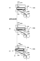
- FIG. 19 is an explanatory diagram briefly showing the operation transition of the stamp side mechanical mechanism 130A of the second embodiment.
- the stamp side mechanical mechanism 130A When the stamp side mechanical mechanism 130A binds the binding target banknotes P at the binding work position in the binding section 22, the stamp side mechanical mechanism 130A fixes the binding target banknotes P between the upper clamp 22B and the lower clamp 22C, and the binding position of the binding target banknotes P In the tightening state shown in FIG. 16 (see FIG. 19A), the first stamp stamping part 142A and the second stamp stamping part 142B are lowered onto the binding band R. Stamp marks S are imprinted on both sides of the binding band R of the binding banknote P (see FIG. 19B).
- the stamp side mechanical mechanism 130A loosens the tightening of the binding band R that is being tightened to the binding position of the binding target banknote P, and moves the binding target banknote P in the short direction through the gripping conveyance unit 27.
- the stamp mark S stamped on both sides of the binding band R of the banknote P is positioned on the binding band R on both side faces of the banknote P to be bound (see FIG. 19C).
- the gripping and transporting unit 27 completes the bound banknote P1 in the binding part 22 and grips and transports the bound banknote P1 into the bound banknote lift part 61, thereby releasing the grip on the short side of the bound banknote P1.
- the discharge conveyance unit 28 conveys the bundled bill P1 to the discharge holding mechanism 63 via the bundled bill lift unit 61 and the pushing mechanism 62.
- the stamp stamping portion described in the claims is the first stamp stamping portion 142A and the second stamp stamping portion 142B, the first stamp stamping portion is the first stamp stamping portion 142A, the second stamp stamping portion is the second stamp stamping portion 142B,
- the stamp drive control unit corresponds to the first stamp drive mechanism 143A, the second stamp drive mechanism 143B, the drive control unit 160, and the control unit 170.
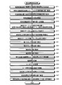
- FIG. 20 is a flowchart showing the processing operation inside the control unit 170 related to the second banknote bundling process.
- the second banknote binding process shown in FIG. 20 is a process of binding the binding band R to the binding position of the binding target banknote P in addition to the process of binding the binding band R to the binding position of the binding target banknote P.
- the stamp mark S is positioned on the binding band R on both sides of P.
- the control unit 170 tightens the binding band R being wound around the binding position of the binding target banknote P on the binding stage 22A through the processing of step S11 to step S19 (step S20), and the tightening detection unit 511.
- step S41 When tightening of the binding band R at the binding position of the binding target banknote P is detected through (step S41), the tightening of the binding band R that is tightening the binding banknote P is loosened according to the pulling-out operation of the drive roller 506.
- the stamp side mechanical mechanism 130A is driven and controlled so as to lower the first stamp stamping part 142A and stamp the stamp mark S on the binding band R on the upper surface of the banknote P of the binding target banknote P (Step S43).
- the stamp-side mechanical mechanism 130A is driven and controlled so that the second stamp stamping part 142B is raised and the stamp mark S is stamped on the binding band R on the lower surface of the banknote P to be bound.
- Flop S44
- control unit 170 tightens the binding band R to the banknote P to be bound in accordance with the rewinding operation of the binding band R by the reverse rotation operation of the driving roller 506 and the feeding roller 509A (step S45), and binds through the tightening detection unit 511.
- step S46 the process proceeds to step S22 so that the other end of the binding band R is thermally welded by the heater unit 505.
- the stamp mark S stamped by the first stamp stamping part 142A and the stamp mark S stamped by the second stamp stamping part 142B are positioned on the binding band R on both sides of the bound banknote P1 completed in step S24. Will do.
- the binding target banknote P is tightened in the state where the binding band R is tightened to the binding position of the binding target banknote P.
- the stamp is stamped on the upper face and the lower face of the banknote P to be bound by the first stamp stamp section 142A and the second stamp stamp section 142B, the tightening operation of the binding band R is performed. Therefore, the stamp mark S can be positioned on the binding band R on both sides of the bundled banknote P1.
- Example 2 in the state where the binding band R is wound around the binding position of 100 binding target banknotes P, the binding target banknotes P are moved in the short side direction of the banknotes, so Since the stamp mark S is stamped on the banknote surface of the binding target banknote P in a state where the binding band R before the binding target banknote movement is wound so that the stamp mark S is positioned on the Even if the bundled banknotes P1 are stacked in the banknote surface direction, the stamp S can be visually recognized from the side surface of the bundled banknotes P1.
- Example 2 the first stamp mark S is positioned on the binding band R disposed on one side surface of the bundled banknote P1, and the second stamp mark S is disposed on the binding band R disposed on the other side surface of the bundled banknote P1. Since the first stamp mark S and the second stamp mark S are imprinted on the binding band R so that the user is positioned, even if the user stacks a plurality of bundled banknotes P1 in the banknote surface direction, The first stamp mark S or the second stamp mark S can be visually recognized from the side surface of the bill P1.
- the binding band R when the binding band R is bound to the binding position of the binding target banknote P, the binding band R is tightened with respect to the binding target banknote P in a state where the binding band R is tightened at the binding position of the binding target banknote P.
- the stamp mark S After tightening R, loosen the stamp mark S on the banknote surface of the banknote P to be bound, and then perform the tightening operation of the binding band R, that is, execute the tightening operation of the binding band R twice in total.
- the stamp mark S may be positioned on the binding band R on both sides of the binding banknote P1 when the binding banknote is completed by one tightening operation of the binding band R.
- Embodiment in this case This will be described below as a third embodiment.
- symbol is attached
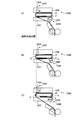
- FIG. 21 is an explanatory diagram briefly showing the operation transition of the stamp side mechanical mechanism of the third embodiment.
- the stamp side mechanical mechanism 130B shown in FIG. 21 is arranged before the banknotes are bundled, that is, in the bundled portion 22.
- the stamp side mechanical mechanism 130B includes a first winding groove 141A, a first stamp stamping portion 142A, a first stamp driving mechanism 143A, a second winding groove 141B, a second stamp stamping portion 142B, and a second stamp driving mechanism 143B. is doing.
- the binding-side banknote P When the stamp-side mechanical mechanism 130B binds the binding target banknotes P at the binding work position in the binding unit 22, the binding-side banknote P is fixed between the upper clamp 22B and the lower clamp 22C, and the binding position of the binding target banknotes P is fixed.
- the first stamp stamping part 142A and the second stamp stamping part 142B are lowered onto the binding band R, and on the binding band R of the binding target banknote P Are stamped on both sides (see FIG. 21B).
- the state in which the binding band R is wound around the binding position of the binding target banknote P shown in FIG. 21 (A) is a sign on both sides of the binding band R of the binding target banknote P as shown in FIG. 21 (B). This corresponds to a loose state in which the stamp S is positioned on the binding band R on the side surface of the binding banknote P1 when the binding band R is tightened.
- the stamp-side mechanical mechanism 130B tightens the binding band R with respect to the binding position of the binding target banknote P in accordance with the rewinding operation of the binding band R by the reverse rotation operation of the driving roller 509, whereby the upper surface of the banknote of the binding target banknote P And the stamp mark S stamped on the binding band R on the lower surface of the banknote is positioned on the binding band R on both sides of the binding banknote P (see FIG. 21C).
- the gripping and transporting unit 27 completes the bound banknote P1 in the binding part 22 and grips and transports the bound banknote P1 into the bound banknote lift part 61, thereby releasing the grip on the short side of the bound banknote P1.
- the discharge conveyance unit 28 conveys the bundled bill P1 to the discharge holding mechanism 63 via the bundled bill lift unit 61 and the pushing mechanism 62.
- FIG. 22 is a flowchart showing the processing operation inside the control unit 170 related to the third banknote bundling process.
- the third banknote bundling process shown in FIG. 22 is a process of binding the binding band R to the binding position of the binding target banknote P in addition to the process of binding the binding band R to the binding position of the binding target banknote P.
- the stamp mark S is positioned on the binding band R on both sides of P.
- the control unit 170 performs the first tightening state (see FIG. 15) in which the binding band R is wound around the binding position of the binding target banknote P on the binding stage 22A through the processes of Steps S11 to S19.
- the stamp-side mechanical mechanism 130B is driven and controlled to lower the stamp stamping part 142A and stamp the stamp mark S onto the binding band R on the upper face of the banknote P to be bound (step S51), and the second stamp stamping part 142B.
- the stamp side mechanical mechanism 130B is driven and controlled so that the stamp mark S is stamped on the binding band R on the lower surface of the banknote P of the binding target banknote P (step S52).
- control part 170 transfers to step S20 in order to fasten the binding band R to the binding target banknote P according to the rewinding operation of the binding band R by the reverse operation of the driving roller 506 and the feeding roller 509A.
- the stamp mark S stamped by the first stamp stamping part 142A and the stamp mark S stamped by the second stamp stamping part 142B are positioned on the binding band R on both sides of the bound banknote P1 completed in step S24. Will do.
- both sides of the binding banknote P1 are subjected to a normal one-time tightening operation of the binding band R of the binding banknote P. Since the stamp mark S is positioned on the binding band R on the surface, the stamp mark S can be positioned on the binding band R on both sides of the binding banknote P1.
- the binding band R is tightened so that the binding band R wound around the binding position of the 100 binding target banknotes P is tightened and the stamp mark S is positioned on the binding band R on the side surface of the binding banknote P1. Since the stamp mark S is stamped on the banknote surface of the binding target banknote P in the unattached state, even if a plurality of bundled banknotes P1 are stacked in the banknote surface direction, the user can The stamp mark S can be visually recognized.
- Example 3 the first stamp mark S is positioned on the binding band R disposed on one side surface of the bundled banknote P1, and the second stamp mark S is disposed on the binding band R disposed on the other side surface of the bundled banknote P1. Since the first stamp mark S and the second stamp mark S are imprinted on the binding band R so that the user is positioned, even if the user stacks a plurality of bundled banknotes P1 in the banknote surface direction, The first stamp mark S or the second stamp mark S can be visually recognized from the side surface of the bill P1.
- the binding target banknote P on the binding stage 22A in the binding section 22 can be moved in the longitudinal direction of the banknote while the short side of the binding target banknote P is gripped through the gripping conveyance section 27, and the binding is performed. Since the binding target banknotes P are moved and adjusted so that the binding position of the binding target banknotes P is positioned at the binding work position of the stage 22A, the short side of the binding target banknotes P is gripped through the gripping transport unit 27. Since the binding target banknotes P on the binding stage 22A are bound, the situation where the binding target banknotes P are separated before binding is avoided, and the binding work speed is improved, thereby binding the work. The efficiency can be greatly improved.
- the binding banknote P1 is held while the binding banknote P1 is being held. Since the gripping and transporting unit 27 keeps gripping the binding target banknote P during the binding operation, the work speed of transporting the binding banknote P1 in the direction of the bundle discharge port 23 is greatly improved. Can be achieved.
- one stamp stamping part 71 is moved and arranged on the bundled banknote conveyance path, and the stamp stamping part 71 binds on the side of the bundled banknote P1 on the banknote forward conveyance direction side among the both sides of the bundled banknote P1.
- the stamp mark S is imprinted on the band R, but the two stamp imprinting parts 71 are moved and arranged on the bundled bill conveyance path, and the stamp mark S is placed on the bundled band on the side of the bundled bill P1 on the banknote forward conveyance direction side.
- the stamp mark S can be imprinted on the binding band R.
- Example 1 the banknote classification of the banknote accumulated
- the banknote type of the banknote first accumulated among the banknotes P to be bound that has reached 100 sheets is acquired, and the standby position of the stamp stamping unit 71 corresponding to the banknote type of the banknote first accumulated is driven and controlled. It goes without saying that the same effect can be obtained even if the setting is made in the section 160.
- the binding position of the binding target banknotes P can be changed according to the banknote type.
- the standby position of the stamp stamping unit 71 needs to be changed. Needless to say, this is possible even without the standby position management unit 175 and the standby position setting unit 176 in the control unit 170.
- the binding position is set for each banknote type of the banknote P to be bound.
- the position information of the portrait printed on the banknote surface of the binding target banknote P is managed, and the binding target R is not covered with the binding band R based on the portrait position information.
- the binding position of the binding band R with respect to the banknote P may be set. In this case, the operation of prohibiting the binding band R from being covered on the portrait of the binding target banknote P can be sufficiently handled.
- the binding position is set for each banknote type of the binding target banknote P.
- the binding position of the binding band R with respect to the binding banknote P is set on the basis of the correct bill or the banknote. Since a situation is also conceivable, in order to deal with such a situation, the binding position of the binding band R with respect to the binding target banknote P may be set based on the correctness information of the correct bill or the damaged bill. The user can recognize the fitness of the bundled banknote P1 at the binding position of the binding band R.
- the central part of the binding target banknote P may be set as the binding position.
- the user recognizes the banknote as a damaged banknote in the binding band R at the center. be able to.
- a plurality of locations of the binding target banknote P may be set at a binding position. be able to.
- the binding position is set for each banknote type of the binding banknote P.
- the binding position of the binding band R with respect to the binding banknote P is set based on the new and old bills of the printing plate.
- the binding position of the binding band R with respect to the binding target banknote P may be set based on the printing information of the new ticket or the old ticket, In this case, the user can recognize the new ticket and the old ticket of the bundled banknote P1 at the binding position of the binding band R.
- one bundling stacking unit 21 is reserved, and the remaining two bundling stacking units 21 are set with different denominations.
- the same effect can be obtained even if the same two denomination banknotes are set in the remaining two bundling stacking portions 21.
- the binding target banknotes P being stacked in the binding stacking unit 21 reach 100 sheets
- the binding target banknotes P are pulled out through the transport unit 42 of the pre-binding transporting section 25, and this binding target is pulled out.
- the bills P are transported onto the binding stage 22A in the binding unit 22, but, for example, the pulled binding target bills P are transported to the vicinity of the entrance of the binding unit 22, and the gripping unit 27A of the gripping transport unit 27 is the binding unit. Needless to say, the same effect can be obtained even if the binding target banknote P is gripped near the entrance 22 and then transported to the work preparation position on the binding stage 22A. .
- the banknote sorting and binding processing apparatus 1 configured by the banknote binding apparatus 3 and the banknote processing apparatus 2 has been described as an example. However, naturally, the same effect can be obtained with the banknote binding apparatus 3 alone. Needless to say.
- the banknote binding device 3 that binds the banknotes P to be bound with the binding band R has been described as an example. However, when binding paper sheets such as gift certificates or securities with the binding band R, However, it goes without saying that the same effect can be obtained.
- each component of each device illustrated is functionally described, and is not necessarily physically configured as illustrated, and a specific aspect of each device is illustrated. Needless to say, it cannot be limited.
- CPU Central Processing Unit
- MPU Micro Processing Unit
- MCU Micro Controller Unit
- all or any part of the program may be executed on a program that is analyzed and executed by a microcomputer) or on hardware based on wired logic.
- the stamp mark is stamped on the binding band so that the stamp mark is positioned on the binding band disposed on the side of the binding banknote in the binding band of the binding banknote. Even if a plurality of bundled banknotes are stacked in the banknote surface direction, the stamp mark can be visually recognized from the side surface of the bundled banknotes, which is useful, for example, in a banknote binding apparatus used in a financial institution or the like.
Landscapes
- Physics & Mathematics (AREA)
- General Physics & Mathematics (AREA)
- Basic Packing Technique (AREA)
Abstract
100枚の結束対象紙幣を結束帯で結束することで結束紙幣を作成する結束部(22)と、結束部(22)にて作成した結束紙幣の結束帯上にスタンプ印が位置すべく、結束帯上にスタンプ印を押印するスタンプ押印部(71)とを有する紙幣結束装置(3)であって、結束紙幣の結束帯の内、結束紙幣側面に配置した結束帯上にスタンプ印が位置するように、結束帯上にスタンプ印を押印すべく、スタンプ押印部(71)を駆動するスタンプ駆動機構(72)を駆動制御する駆動制御部(160)を有するようにしたので、ユーザは、複数束の結束紙幣を紙幣面方向に積み重ねたとしても、結束紙幣の側面からスタンプ印を視認できる。
Description
本発明は、例えば、特定金種の紙幣を所定枚数単位で結束する紙幣結束装置及び紙幣結束方法に関する。
従来、このような紙幣結束装置では、所定枚数の結束対象紙幣を結束帯で結束する結束部と、結束部で結束した結束紙幣の表面又は裏面に配置した結束帯上にスタンプ印を押印するスタンプ押印部とを有する技術が知られている(例えば、特許文献1及び2参照)。
特許文献1では、結束部で結束した結束紙幣の表面又は裏面に配置した結束帯上に銀行名のスタンプ印を押印するようにしたので、ユーザは、結束帯上のスタンプ印で結束紙幣を作成した銀行名を視認することができる。
また、特許文献2では、結束部で結束した結束紙幣の表面又は裏面に配置した結束帯上に損券等のスタンプ印を押印するようにしたので、ユーザは、結束帯上のスタンプ印で損券の結束紙幣と視認することができる。
しかしながら、上記従来の紙幣結束装置では、結束部で結束した結束紙幣の表面又は裏面に配置した結束帯上にスタンプ印を押印するようにしたので、例えば、複数束の結束紙幣を紙幣面方向に積み重ねた場合、結束紙幣の表面又は裏面に押印したスタンプ印を視認することができないといった事態が考えられる。
本発明は上記点に鑑みてなされたものであり、その目的とするところは、複数束の結束紙幣を紙幣面方向に積み重ねたとしても、結束紙幣の側面からスタンプ印を視認することができる紙幣結束装置及び紙幣結束方法を提供することにある。
上記目的を達成するために本発明の紙幣結束装置は、結束対象紙幣を結束帯で結束することで結束紙幣を作成する結束部と、前記結束部にて作成した前記結束紙幣の結束帯上にスタンプ印が位置すべく、前記結束帯上にスタンプ印を押印するスタンプ押印部とを有する紙幣結束装置であって、前記結束紙幣の前記結束帯の内、前記結束紙幣側面に配置した前記結束帯上に前記スタンプ印が位置するように、前記結束帯上に前記スタンプ印を押印すべく、前記スタンプ押印部を駆動制御するスタンプ駆動制御部を有することを要件とする。
また、本発明の紙幣結束装置は、上記発明の構成において、前記結束部にて作成した前記結束紙幣を排出方向に搬送する束搬送部を有し、前記スタンプ駆動制御部は、前記束搬送部にて前記結束紙幣を搬送する搬送路上で、搬送中の前記結束紙幣側面の前記結束帯上に前記スタンプ印が位置するように、前記搬送路上に前記スタンプ押印部を移動配置して前記結束帯上に前記スタンプ印を押印すべく、前記スタンプ押印部を駆動制御することを要件とする。
また、本発明の紙幣結束装置は、上記発明の構成において、前記束搬送部は、前記結束紙幣の短手側端部を把持して前記結束紙幣を搬送することを要件とする。
また、本発明の紙幣結束装置は、上記発明の構成において、前記結束部は、所定枚数の結束対象紙幣の結束位置に前記結束帯を巻回した状態で、前記結束対象紙幣を紙幣短手方向に移動することで、前記結束紙幣側面の前記結束帯上に前記スタンプ印が位置するように、前記結束対象紙幣移動前の前記結束帯を巻回した状態で前記結束対象紙幣の紙幣面上に前記スタンプ印を押印すべく、前記スタンプ押印部を駆動制御することを要件とする。
また、本発明の紙幣結束装置は、上記発明の構成において、前記結束部は、所定枚数の結束対象紙幣の結束位置に巻回した前記結束帯を締め付けて、前記結束紙幣側面の前記結束帯上に前記スタンプ印が位置するように、前記結束帯の締め付け前の状態で前記結束対象紙幣の紙幣面上に前記スタンプ印を押印すべく、前記スタンプ押印部を駆動制御することを要件とする。
また、本発明の紙幣結束装置は、上記発明の構成において、前記スタンプ押印部は、前記結束紙幣の両側面の内、一方の側面に配置した前記結束帯上に第1スタンプ印を押印する第1スタンプ押印部と、前記結束紙幣の両側面の内、他方の側面に配置した前記結束帯上に第2スタンプ印を押印する第2スタンプ押印部とを有し、前記スタンプ駆動制御部は、前記結束紙幣の前記一方の側面に配置した前記結束帯上に前記第1スタンプ印が位置すると共に、前記結束紙幣の前記他方の側面に配置した前記結束帯上に前記第2スタンプ印が位置するように、前記結束帯上に前記第1スタンプ印及び前記第2スタンプ印を押印すべく、前記第1スタンプ押印部及び前記第2スタンプ押印部を駆動制御することを要件とする。
また、上記目的を達成するために本発明の紙幣結束方法は、結束対象紙幣を結束帯で結束することで結束紙幣を作成する紙幣結束ステップと、前記紙幣結束ステップにて作成した前記結束紙幣の結束帯上にスタンプ印が位置すべく、前記結束帯上にスタンプ印を押印するスタンプ押印ステップとを含む紙幣結束方法であって、前記スタンプ押印ステップは、前記結束紙幣の前記結束帯の内、前記結束紙幣側面に配置した前記結束帯上に前記スタンプ印が位置するように、前記結束帯上に前記スタンプ印を押印することを要件とする。
上記のように構成された本発明の紙幣結束装置では、結束紙幣の結束帯の内、結束紙幣側面に配置した結束帯上にスタンプ印が位置するように、結束帯上にスタンプ印を押印するようにしたので、ユーザは、複数束の結束紙幣を紙幣面方向に積み重ねたとしても、結束紙幣の側面からスタンプ印を視認することができるという効果を奏する。
また、本発明の紙幣結束装置では、上記発明の効果に加えて、結束紙幣を排出方向に搬送する搬送路上で、搬送中の結束紙幣側面の結束帯上にスタンプ印が位置するように、搬送路上にスタンプ押印部を移動配置して結束帯上にスタンプ印を押印するようにしたので、ユーザは、複数束の結束紙幣を紙幣面方向に積み重ねたとしても、結束紙幣の側面からスタンプ印を視認することができるという効果を奏する。
また、本発明の紙幣結束装置では、上記発明の効果に加えて、結束紙幣の短手側端部を把持して結束紙幣を搬送するようにしたので、結束紙幣の側面である長手側端部からスタンプ印を押印することができるという効果を奏する。
また、本発明の紙幣結束装置では、上記発明の効果に加えて、所定枚数の結束対象紙幣の結束位置に結束帯を巻回した状態で、結束対象紙幣を紙幣短手方向に移動することで、結束紙幣側面の結束帯上にスタンプ印が位置するように、結束対象紙幣移動前の結束帯を巻回した状態で結束対象紙幣の紙幣面上にスタンプ印を押印するようにしたので、ユーザは、複数束の結束紙幣を紙幣面方向に積み重ねたとしても、結束紙幣の側面からスタンプ印を視認することができるという効果を奏する。
また、本発明の紙幣結束装置では、上記発明の効果に加えて、所定枚数の結束対象紙幣の結束位置に巻回した結束帯を締め付けて、結束紙幣側面の結束帯上にスタンプ印が位置するように、結束帯の締付前の状態で結束対象紙幣の紙幣面上にスタンプ印を押印するようにしたので、ユーザは、複数束の結束紙幣を紙幣面方向に積み重ねたとしても、結束紙幣の側面からスタンプ印を視認することができるという効果を奏する。
また、本発明の紙幣結束装置では、上記発明の効果に加えて、結束紙幣の一方の側面に配置した結束帯上に第1スタンプ印が位置すると共に、結束紙幣の他方の側面に配置した結束帯上に第2スタンプ印が位置するように、結束帯上に第1スタンプ印及び第2スタンプ印を押印するようにしたので、ユーザは、複数束の結束紙幣を紙幣面方向に積み重ねたとしても、結束紙幣の側面から第1スタンプ印又は第2スタンプ印を視認することができるという効果を奏する。
また、上記のように構成された本発明の紙幣結束方法では、結束紙幣の結束帯の内、結束紙幣側面に配置した結束帯上にスタンプ印が位置するように、結束帯上にスタンプ印を押印するようにしたので、ユーザは、複数束の結束紙幣を紙幣面方向に積み重ねたとしても、結束紙幣の側面からスタンプ印を視認することができるという効果を奏する。
3 紙幣結束装置
22 結束部
71 スタンプ押印部
72 スタンプ駆動機構
160 駆動制御部
170 制御部
130 スタンプ側メカ機構
130A スタンプ側メカ機構
130B スタンプ側メカ機構
142A 第1スタンプ押印部
142B 第2スタンプ押印部
143A 第1スタンプ駆動機構
143B 第2スタンプ駆動機構
P 結束対象紙幣
P1 結束紙幣
S スタンプ印
22 結束部
71 スタンプ押印部
72 スタンプ駆動機構
160 駆動制御部
170 制御部
130 スタンプ側メカ機構
130A スタンプ側メカ機構
130B スタンプ側メカ機構
142A 第1スタンプ押印部
142B 第2スタンプ押印部
143A 第1スタンプ駆動機構
143B 第2スタンプ駆動機構
P 結束対象紙幣
P1 結束紙幣
S スタンプ印
以下、図面に基づき本発明の紙幣結束装置の実施例について詳細に説明する。
まず、最初に本実施例の概要を説明するとすれば、その概要は、例えば、100枚の結束対象紙幣を結束帯で結束することで結束紙幣を作成する結束部と、結束部にて作成した結束紙幣の結束帯上にスタンプ印が位置すべく、結束帯上にスタンプ印を押印するスタンプ押印部とを有する紙幣結束装置であって、結束紙幣の結束帯の内、結束紙幣側面に配置した結束帯上にスタンプ印が位置するように、結束帯上にスタンプ印を押印すべく、スタンプ押印部を駆動制御するスタンプ駆動制御部を有している。
その結果、本実施例では、結束紙幣の結束帯の内、結束紙幣側面に配置した結束帯上にスタンプ印が位置するように、結束帯上にスタンプ印を押印するようにしたので、ユーザは、複数束の結束紙幣を紙幣面方向に積み重ねたとしても、結束紙幣の側面からスタンプ印を視認することができる。
図1は、実施例1の紙幣分類結束処理装置の外観構成を端的に示す斜視図、図2は、紙幣分類結束処理装置内部の概略構成を示す説明図である。
紙幣分類結束処理装置1は、取引紙幣を連続入金し、これら入金した紙幣を紙幣種別毎に分類集積すると共に、その紙幣の入金枚数を紙幣種別毎に計数する紙幣処理装置2と、紙幣処理装置2にて分類した特定金種の紙幣を所定枚数、例えば100枚単位で結束する紙幣結束装置3と、例えば、計数結果等の各種情報を表示する表示装置4とを有している。
紙幣処理装置2は、取引紙幣を装置内に投入するホッパ部11と、このホッパ部11に投入した紙幣を1枚単位で繰り出す繰出部12と、この繰出部12にて繰り出した紙幣を搬送する搬送ベルト等の紙幣搬送部13と、この紙幣搬送部13で搬送した紙幣の種別を識別する紙幣識別部14と、紙幣識別部14の紙幣種別、例えば、表裏情報に基づき、紙幣搬送部13で搬送した紙幣を表面及び裏面の内、何れか一方の特定面に向けるように紙幣を反転する紙幣反転部15とを有している。
また、紙幣処理装置2は、紙幣種別に応じて紙幣搬送部13で搬送した紙幣を分類集積する4個のスタッカ16と、スタッカ16及び紙幣結束装置3に対応する紙幣種別に該当しない紙幣をリジェクトする2個の第1リジェクト部17とを有している。尚、スタッカ16及び第1リジェクト部17には、搬送紙幣を1枚単位で紙幣集積空間内の所定位置に集積する羽根車16E(17C)を配置している。
4個のスタッカ16は、設定中の紙幣種別毎に搬送紙幣を分類集積し、第1スタッカ16A、第2スタッカ16B、第3スタッカ16C及び第4スタッカ16Dで構成している。尚、紙幣種別とは、例えば、ユーロ紙幣の場合、5ユーロ、10ユーロ、20ユーロ、50ユーロ、100ユーロ、200ユーロ及び500ユーロの7種類の金種の他に、真券・偽券を識別する真偽情報、正券・損券を識別する正損情報や、表裏を識別する表裏情報等がある。また、その他の通貨では、金種毎の新券・旧券を識別する刷版情報等もある。
また、紙幣結束装置3は、紙幣処理装置2内部の紙幣搬送路18から本装置内へ特定金種紙幣を搬送する紙幣搬送部13と、装置内の上下方向に三段配置し、その搬送された特定金種紙幣を分類集積する3個の結束用集積部21と、これら3個の結束用集積部21の下方位置に配置し、結束用集積部21に分類集積する結束対象紙幣が所定枚数、例えば、100枚に到達した場合、その100枚の結束対象紙幣を結束帯で結束する結束部22とを有している。
さらに、紙幣結束装置3は、ホッパ部11近傍に配置し、結束部22にて結束した紙幣、すなわち結束紙幣をオペレータ側に放出する束放出口23と、結束用集積部21の近傍に配置し、取引終了時に結束用集積部21に集積中の端数紙幣をオペレータ側に放出する端数返却口24とを有している。
また、紙幣結束装置3は、結束用集積部21に集積中の結束対象紙幣を結束部22又は端数返却口24に把持搬送する結束前搬送部25と、結束部22内の結束対象紙幣を紙幣長手方向に把持搬送すると共に、結束部22にて結束した結束紙幣を束放出口23に搬送する結束後搬送部26とを有している。
結束前搬送部25は、結束用集積部21に集積中の結束対象紙幣の内、100枚の結束対象紙幣の長手側を把持して、これら100枚の結束対象紙幣を結束部22内の結束ステージ22A上に搬送すると共に、取引終了時に、結束用集積部21に集積中の結束対象紙幣の内、集積中の100枚に満たない端数紙幣を把持して、これら端数紙幣を端数返却口24へ搬送するものである。尚、結束部22の結束ステージ22Aとは、結束部22の結束作業領域に相当するものである。
また、結束後搬送部26は、結束前搬送部25で結束対象紙幣を結束部22内の結束ステージ22A上に搬送した後、この搬送した結束対象紙幣の短手側を把持し、この把持した結束対象紙幣を紙幣長手方向に移動調整すると共に、結束部22にて結束した結束紙幣を把持搬送する把持搬送部27と、この把持搬送部27にて把持搬送した結束紙幣を束放出口23に搬送する放出搬送部28とを有している。
把持搬送部27は、結束前搬送部25で結束部22内の結束ステージ22A上の作業準備位置に搬送した後、この作業準備位置で結束対象紙幣の短手側を把持するものである(後述する図6(C)参照)。尚、結束前搬送部25は、把持搬送部27による結束対象紙幣の短手側の把持動作に応じて、結束対象紙幣の長手側の把持を開放するものである。
尚、作業準備位置とは、結束作業を実行する結束ステージ22A上の結束作業位置に対して結束対象紙幣の移動調整、すなわち結束対象紙幣長手方向への移動を開始する位置に相当するものである。また、結束作業位置は、結束対象紙幣に結束帯を結束する作業位置に相当するものである。
把持搬送部27は、結束部22の結束ステージ22A上の作業準備位置に結束対象紙幣を把持すると、結束ステージ22A上の結束作業位置に結束対象紙幣の結束位置を位置決め配置すべく、結束対象紙幣を結束対象紙幣の長手方向に移動調整するものである(後述する図6(E)参照)。尚、結束部22は、この結束作業位置に結束対象紙幣の結束位置を配置することで、同結束対象紙幣の結束位置に結束帯を巻回することができるものである。
把持搬送部27は、結束部22を通じて結束ステージ22A上の結束作業位置で、結束対象紙幣の短手側を把持したまま、結束対象紙幣の結束作業が完了すると、その結束紙幣を作業準備位置に搬送し、この結束紙幣を放出搬送部28内に搬送するものである。
放出搬送部28は、把持搬送部27にて把持搬送した結束紙幣を紙幣結束装置3上部に搬送する結束紙幣リフト部61と、この結束紙幣リフト部61にて紙幣結束装置3上部に搬送した結束紙幣を束放出口23方向(装置正面方向)に押し出す押出機構62と、押出機構62で装置正面に押し出した結束紙幣を収納すると共に、結束紙幣を束放出口23に放出保持する放出保持機構63とを有している。
また、紙幣分類結束処理装置1は、ホッパ部11と接続し、スタッカ16の上方位置に配置した第1搬送路18A、第1搬送路18Aと接続し、スタッカ16の配置方向に折り返すように配置した第2搬送路18B及び、第2搬送路18Bと接続すると共に、スタッカ16及び結束用集積部21と接続する第3搬送路18Cを含む紙幣搬送路18を有している。尚、紙幣識別部14は、第1搬送路18A上に配置し、紙幣反転部15は、第2搬送路18B上に配置しているものとする。また、第2搬送路18Bは、紙幣分類結束処理装置1の第1搬送路18A及び第3搬送路18Cに接続する着脱可能なユニットで構成するものである。
また、紙幣搬送路18上には、搬送路上の分岐箇所、合流箇所や装置間の連結箇所等の搬送紙幣の進入及び通過を検知する検知センサ19を夫々配置するものである。
第3搬送路18Cの最終端には、第2リジェクト部20を配置しているものである。尚、第2リジェクト部20には、搬送紙幣を1枚単位で紙幣集積空間内の所定位置に集積する札たたきベルト20Aを配置している。
また、紙幣分類結束処理装置1内の紙幣搬送路18上の分岐箇所には、紙幣搬送路18上を搬送する搬送紙幣を、スタッカ16、結束用集積部21、第1リジェクト部17又は第2リジェクト部20に振り分ける分岐部13Aを配置している。尚、分岐部13Aは、検知センサ19を通じて搬送紙幣の先端の進入を検知すると、図示せぬソレノイドが駆動することで搬送紙幣を振り分けるものである。
紙幣反転部15は、紙幣識別部14の紙幣種別である表裏情報に基づき、紙幣反転部15の手前に設けられた分岐部13Aで反転ルート又は無反転ルートに振り分け、紙幣の表面及び裏面の内、特定面に揃えて第3搬送路18Cに搬送するものである。
反転ルートでは、紙幣の搬送方向に延在する曲面をもった反転部材15Aと、一部が反転部材15Aの曲面に沿うようにして、反転部材15Aの長手方向に対して斜めに掛けられた、図示せぬ搬送ベルトと、搬送ベルトを駆動する図示せぬ駆動モータと、搬送ベルト及び反転部材15Aで挟まれ、反転部材15Aの曲面に巻き付けられながら、反転部材15Aの長手方向に搬送される紙幣の表面を摺動案内する図示せぬガイド部とを有している(日本国特許第4119664号公報参照)。
紙幣反転部15では、駆動モータで搬送ベルトが駆動されている状態で紙幣が搬送されると、紙幣が搬送ベルトと反転部材15Aとの間に挟まれ、搬送ベルトの移動に追従して搬送方向に移動するものである。この際、搬送ベルトは、反転部材15Aの長手方向に対して斜めに沿うように曲面に掛けられているため、紙幣は、曲面に巻き付けられながら搬送されると共に、自転しながら表裏反転されることになる。また、表裏反転の際、ガイド部で紙幣の表面を摺動案内させることで、搬送途中における紙幣の動きを規制しながら紙幣を確実に表裏反転させることが可能になるものである。
図3は、紙幣反転部15の反転処理を端的に示す説明図である。
紙幣反転部15は、図3に示すように、例えば、搬送紙幣のA面(表面)をA面(表面)のまま、第3搬送路18Cに搬送する場合、無反転ルートを通じてA面(表面)のまま、搬送紙幣を第3搬送路18Cに搬送するものである。
また、図3に示すように、例えば、B面(裏面)の搬送紙幣をA面(表面)に反転して第3搬送路18Cに搬送する場合、反転ルートを通じて紙幣反転部15の長手反転処理を実行することで、B面(裏面)をA面(表面)に反転し、その搬送紙幣を第3搬送路18Cに搬送するものである。
また、結束用集積部21の背面壁部には、結束前搬送部25のハンド部41(図2参照)の集積空間31内への進入を可能とする、例えば3個の切欠部を形成し、切欠部を通じて進入したハンド部41が集積空間31内の結束対象紙幣の長手側を把持し、その把持した結束対象紙幣を集積空間31から引抜可能にすべく、その背面壁部の下部は開閉可能なシャッタ構成としている。
また、結束前搬送部25は、図2に示すように、結束用集積部21に集積中の結束対象紙幣の長手側を一括把持するハンド部41を備えた搬送ユニット42と、搬送ユニット42を前後方向(水平方向)に移動させる水平移動機構43と、搬送ユニット42を上下方向(垂直方向)に移動させる垂直移動機構44とを有している。
垂直移動機構44は、紙幣結束装置3内の下端から上端に到る垂直に設置されたガイド軸44Aと、このガイド軸44Aで案内して搬送ユニット42を昇降する駆動ベルト44Bとを有している。
結束前搬送部25内の搬送ユニット42は、水平移動機構43内の駆動ベルト43Aを通じて前進又は後退可能なハンド部41を備え、ハンド部41は、例えば、上ハンド41Aの3本の把持爪及び、下ハンド41Bの3本の把持爪同士を対峙し、把持爪同士で結束用集積部21に集積中の結束対象紙幣の長手側を把持するものである。尚、下ハンド41Bは、固定であるのに対し、上ハンド41Aは、駆動ベルト41Cを通じて上下動可能である。
搬送ユニット42は、上ハンド41A及び下ハンド41Bの把持爪同士で結束対象紙幣の長手側を把持し、把持した結束対象紙幣を結束部22内の結束ステージ22A上の作業準備位置又は端数返却口24に搬送するものである。
結束前搬送部25は、搬送ユニット42を通じて100枚の結束対象紙幣の長手側を把持した状態で、結束部22内の結束ステージ22A上の作業準備位置に結束対象紙幣を搬送配置するものである。
把持搬送部27は、搬送ユニット42を通じて100枚の結束対象紙幣の長手側を把持した状態で、結束部22内の結束ステージ22A上の作業準備位置の100枚の結束対象紙幣の短手側を把持するものである。尚、結束前搬送部25内の搬送ユニット42は、把持搬送部27の結束対象紙幣の短手側の把持動作に応じて、搬送ユニット42側で把持した結束対象紙幣の長手側の把持を開放し、待機位置に移動するものである。
把持搬送部27は、紙幣の短手側を一括把持する上下ハンドの把持部27Aを有し、把持部27Aは、結束対象紙幣の結束位置を結束ステージ22A上の結束作業位置に位置決め配置すべく、作業準備位置から結束対象紙幣の長手方向に結束対象紙幣を移動調整するものである。
結束部22は、把持搬送部27の把持部27Aを通じて結束対象紙幣の短手側を把持した状態で、結束対象紙幣の結束位置を結束ステージ22A上の結束作業位置に位置決め配置すると、結束対象紙幣の結束位置に結束帯を結束する結束作業を実行するものである。
また、結束部22は、結束帯を収容する結束帯リール501と、結束対象紙幣の結束位置を結束作業位置に位置決め配置した状態で、結束帯リール501から引き出した結束帯の先端を結束対象紙幣の結束位置に止める結束帯止め部502と、結束対象紙幣に止めた結束帯を結束帯リール501から引き出し、引き出した結束帯を結束対象紙幣の結束位置に巻回する旋回アーム503と、結束対象紙幣の結束位置に巻回した結束帯の他端を切断するカッタ部504と、そのカッタ部504で切断した結束帯の他端を熱溶着するヒータ部505とを有し、結束対象紙幣を結束帯で結束することで、結束紙幣を作成するものである。
また、把持搬送部27の把持部27Aは、図2に示すように、結束部22を通じて結束対象紙幣の結束動作が完了すると、この結束紙幣を作業準備位置に戻し、結束紙幣搬送路を通じて結束紙幣を放出搬送部28内の結束紙幣リフト部61内に搬送するものである。尚、把持搬送部27は、結束紙幣を結束紙幣リフト部61内に搬送すると、結束紙幣の短手側の把持を開放するものである。
また、把持搬送部27で結束紙幣を搬送する結束紙幣搬送路の上部には、図2に示すように、結束紙幣搬送路上に搬送する結束紙幣側面に配置した結束帯上にスタンプ印を押印するスタンプ押印部71を駆動すると共に、このスタンプ押印部71を収納可能にするスタンプ駆動機構72を配置している。
スタンプ駆動機構72は、結束部22を通じて結束紙幣の作成が完了すると、結束紙幣搬送路上を搬送する結束紙幣側面の結束帯に、スタンプ押印部71の押印面が平行配置するように、搬送路幅方向にスタンプ押印部71を移動配置すると共に、この待機位置から結束紙幣搬送路上にスタンプ押印部71を降下することで、スタンプ押印部71の押印面が結束紙幣の搬送動作に応じて到来する結束紙幣側面の結束帯に対向するように結束紙幣搬送路上にスタンプ押印部71を配置するものである。
スタンプ押印部71は、その押印面上に、結束紙幣の前進搬送動作に応じて結束紙幣側面の結束帯Rが当接することで、結束紙幣側面の結束帯R上にスタンプ印を押印するものである。
また、スタンプ駆動機構72は、結束紙幣側面の結束帯R上へのスタンプ印の押印が完了すると、スタンプ押印部71を結束紙幣搬送路上から上昇し、そのスタンプ押印部71を内部に収納するものである。
そして、把持搬送部27は、結束紙幣搬送路を通じてスタンプ印を押印した結束紙幣を放出搬送部28内の結束紙幣リフト部61内に搬送するものである。
結束紙幣リフト部61は、把持搬送部27の把持部27Aにて把持搬送した結束紙幣を紙幣結束装置3上部の押出機構62に搬送するものである。
押出機構62は、結束紙幣リフト部61にて紙幣結束装置3上部に搬送した結束紙幣を束放出口23方向(装置正面方向)の放出保持機構63に押出搬送するものである。
放出保持機構63は、押出機構62に押出搬送された結束紙幣を収納する結束紙幣収納部63Aと、結束紙幣収納部63A内に収納した結束紙幣を載置する結束紙幣ステージ63Bとを有し、押出機構62に押出搬送された結束紙幣が結束紙幣ステージ63B上の最上部の結束紙幣の上に収納できるように、結束紙幣ステージ63Bの高さを調整するものである。
図4は、紙幣分類結束処理装置1内部の概略構成を示すブロック図である。
図4に示す紙幣分類結束処理装置1は、紙幣識別部14の他に、紙幣処理装置2内部のスタッカ側メカ機構110と、紙幣結束装置3内部の結束側メカ機構120と、紙幣結束装置3内部のスタンプ側メカ機構130と、様々なコマンドを入力する操作部140と、表示装置4を表示制御する表示制御部150と、スタッカ側メカ機構110、結束側メカ機構120及びスタンプ側メカ機構130を駆動制御する駆動制御部160と、この紙幣分類結束処理装置1全体を制御する制御部170とを有している。
スタッカ側メカ機構110は、繰出部12、紙幣搬送部13、紙幣反転部15、羽根車16E(17C)及び、紙幣処理装置2内部の検知センサ19及び分岐部13Aを有している。
結束側メカ機構120は、紙幣結束装置3内部の検知センサ19、紙幣搬送部13、分岐部13A、結束部22、結束前搬送部25及び結束後搬送部26を有している。尚、結束後搬送部26は、把持搬送部27及び放出搬送部28を有している。
スタンプ側メカ機構130は、スタンプ押印部71及びスタンプ駆動機構72を有している。
制御部170は、例えば、スタッカ16、第1リジェクト部17、第2リジェクト部20及び結束用集積部21に集積する紙幣種別(集積紙幣)を設定するものである。尚、制御部170は、例えば、第1スタッカ16Aに5ユーロ紙幣、第2スタッカ16Bに50ユーロ紙幣、第3スタッカ16Cに100ユーロ紙幣、第4スタッカ16Dに200ユーロ紙幣、第1リジェクト部17Aに500ユーロ紙幣、更に初期設定として、第1結束用集積部21Aに10ユーロ紙幣、第2結束用集積部21Bに20ユーロ紙幣、第3結束用集積部21Cに予備を設定するものである。尚、第1リジェクト部17Aについては、500ユーロ紙幣のようにまれな種別の紙幣を集積するスタッカとしても使用可能である。
また、制御部170は、検知センサ19の検知結果に基づき、搬送路上の紙幣詰まり(ジャム)等の障害を認識するものである。
また、制御部170は、3個の結束用集積部21の内、一の結束用集積部21に集積中の結束対象紙幣Pが100枚に到達したか否かを判定する結束枚数判定部171と、結束枚数判定部171にて結束用集積部21に集積中の結束対象紙幣Pが100枚に到達した場合、100枚に到達した結束対象紙幣Pの内、この結束用集積部21に最後に集積した紙幣の紙幣種別を取得する紙幣種別取得部172と、紙幣種別に応じた結束位置を登録管理する結束位置管理部173と、紙幣種別取得部172にて取得した紙幣種別に対応する結束位置を結束位置管理部173から取得し、取得した結束位置を設定する結束位置設定部174とを有している。
紙幣種別取得部172は、第1結束用集積部21A、第2結束用集積部21B又は第3結束用集積部21Cの何れか一に集積中の結束対象紙幣が100枚に到達した場合、紙幣識別部14の識別結果に基づき、100枚の結束対象紙幣の内、この結束用集積部21に最後に集積した紙幣、すなわち最上面に配置した結束対象紙幣の紙幣種別を取得するものである。
結束位置管理部173は、紙幣種別単位で紙幣長手方向の結束位置を管理するものである。
結束位置設定部174は、紙幣種別取得部172にて結束対象紙幣の最後に集積した紙幣の紙幣種別を取得すると、紙幣種別に対応する結束位置を結束位置管理部173から読み出し、読み出した結束位置を駆動制御部160内に設定するものである。
その結果、駆動制御部160は、結束位置設定部174にて設定した結束位置に基づき、結束部22の結束ステージ22A上の結束作業位置に結束対象紙幣の結束位置を位置決め配置すべく、把持搬送部27の把持部27Aを駆動制御するものである。
また、制御部170は、紙幣種別に応じた結束位置の結束帯上にスタンプ押印部71の押印面が平行配置するように、スタンプ押印部71の待機位置を紙幣種別毎に管理する待機位置管理部175と、紙幣種別取得部172にて取得した紙幣種別に対応する待機位置を待機位置管理部175から取得し、取得した待機位置を設定する待機位置設定部176とを有している。
また、待機位置設定部176は、紙幣種別取得部172にて結束対象紙幣の最後に集積した紙幣の紙幣種別を取得すると、紙幣種別に対応するスタンプ押印部71の待機位置を待機位置管理部175から読み出し、読み出したスタンプ押印部71の待機位置を駆動制御部160内に設定するものである。
その結果、駆動制御部160は、待機位置設定部176にて設定したスタンプ押印部71の待機位置に基づき、紙幣種別の結束位置にスタンプ押印部71の押印面を平行配置すべく、スタンプ駆動機構72を通じてスタンプ押印部71を移動配置すると共に、その位置でスタンプ押印部71を結束紙幣搬送路上に降下してスタンプ押印部71の押印面を、結束紙幣搬送路上を搬送する結束紙幣側面の結束帯に対向配置するものである。
また、駆動制御部160は、紙幣識別部14にて識別した搬送紙幣の紙幣種別を取得すると、紙幣搬送路18を搬送中の搬送紙幣がスタッカ16、又は結束用集積部21に設定中の紙幣種別(集積紙幣)の場合、この搬送紙幣を該当スタッカ16、又は結束用集積部21に分類集積すべく、紙幣搬送部13及び分岐部13Aを駆動制御するものである。
また、駆動制御部160は、紙幣搬送路18を搬送中の搬送紙幣がスタッカ16及び結束用集積部21に設定中の紙幣以外の場合や、搬送異常等により識別できない紙幣の場合、この搬送紙幣を第1リジェクト部17に搬送すべく、紙幣搬送部13及び分岐部13Aを駆動制御するものである。尚、第1リジェクト部17Aは、紙幣種別を設定可能であるため、駆動制御部160は、紙幣識別部14にて識別した搬送紙幣の紙幣種別を取得すると、紙幣搬送路18を搬送中の搬送紙幣が第1リジェクト部17Aに設定中の紙幣種別(集積紙幣)の場合、この搬送紙幣を第1リジェクト部17Aに分類集積すべく、紙幣搬送部13及び分岐部13Aを駆動制御するものである。
また、駆動制御部160は、紙幣搬送路18を搬送中の搬送紙幣が結束用集積部21に設定中の紙幣種別(集積紙幣)の場合、この搬送紙幣を結束用集積部21に分類集積すべく、紙幣搬送部13及び分岐部13Aを駆動制御するものである。
駆動制御部160は、例えば、第1結束用集積部21Aに10ユーロ紙幣、第2結束用集積部21Bに20ユーロ紙幣、第3結束用集積部21Cに予備を紙幣種別(集積紙幣)として設定中に、第1結束用集積部21Aに集積する結束対象紙幣が100枚に到達した場合、結束前搬送部25の搬送ユニット42内のハンド部41を通じて第1結束用集積部21Aに集積中の結束対象紙幣を引き抜くべく、結束前搬送部25を駆動制御するものである。
さらに、制御部170は、第1結束用集積部21Aに集積する10ユーロ紙幣が100枚に到達した場合、予備の第3結束用集積部21Cの紙幣種別(集積紙幣)を10ユーロ紙幣に切替設定すると共に、搬送ユニット42内のハンド部41を通じて100枚に到達した10ユーロ紙幣を引き抜いて紙幣集積可能となる第1結束用集積部21Aの紙幣種別(集積紙幣)を予備に切替設定するものである。
図5は、結束前搬送部25の動作遷移を端的に示す説明図である。
結束前搬送部25は、搬送ユニット42を通じて結束用集積部21に集積中の結束対象紙幣Pを引き抜く場合、引抜対象の結束用集積部21内のステージ部32を最下端まで降下する(図5(A)参照)。
さらに、結束前搬送部25は、ガイド軸44Aを通じた駆動ベルト44Bの動作で引抜対象の結束用集積部21に対する位置、すなわち結束用集積部21に集積中の結束対象紙幣Pの最下端の紙幣よりも下ハンド41Bの上面が低くなる位置にまで搬送ユニット42を降下する(図5(A)参照)。
さらに、結束前搬送部25は、結束用集積部21に集積中の結束対象紙幣Pの最上端の紙幣よりも上ハンド41Aの下面が高くなる位置まで駆動ベルト41Cを通じて搬送ユニット42の上ハンド41Aを上昇する(図5(A)参照)。その結果、上ハンド41A及び下ハンド41B間は拡開した状態となる。
また、搬送ユニット42は、水平移動機構43の駆動ベルト43Aの動作に応じて前進し、この前進動作に応じて結束用集積部21の背面壁部31Bに形成した切欠部31Cを通じて結束用集積部21内に上ハンド41A及び下ハンド41Bが進入し、これら上ハンド41A及び下ハンド41B間に結束対象紙幣Pが位置することになる(図5(B)参照)。
さらに、搬送ユニット42は、駆動ベルト41Cを通じて上ハンド41Aを下降し、この下降動作に応じて、上ハンド41A及び下ハンド41B間でステージ部32上の結束対象紙幣Pの長手側を強固に把持することになる(図5(C)参照)。
そして、搬送ユニット42は、水平移動機構43の駆動ベルト43Aの動作に応じて後退し、この後退動作に応じて、上ハンド41A及び下ハンド41Bで把持した結束対象紙幣Pを、垂直移動機構44を通じて結束部22内の結束ステージ22A上の作業準備位置又は端数返却口24に移動可能な状態となる(図5(D)参照)。
また、図4に示す駆動制御部160は、結束用集積部21に集積する結束対象紙幣Pが100枚に到達した場合、背面壁部31Bの切欠部31Cを通じて結束前搬送部25内の搬送ユニット42のハンド部41が集積空間31内に進入し、このハンド部41でステージ部32上の結束対象紙幣Pの長手側を把持し、この把持した結束対象紙幣Pを結束用集積部21から引き抜き、この引き抜いた結束対象紙幣Pを、水平移動機構43、垂直移動機構44及び水平移動機構43を通じて結束部22に搬送すべく、結束前搬送部25を駆動制御するものである。
また、駆動制御部160は、取引終了時に、結束用集積部21に集積中の結束対象紙幣Pが100枚に満たない場合、背面壁部31Bの切欠部31Cを通じて搬送ユニット42のハンド部41が集積空間31内に進入し、このハンド部41でステージ部32上の結束対象紙幣Pの長手側を把持し、この把持した端数の結束対象紙幣Pを結束用集積部21から引き抜き、この引き抜いた端数の結束対象紙幣Pを、水平移動機構43、垂直移動機構44及び水平移動機構43を通じて端数返却口24に搬送すべく、結束前搬送部25を駆動制御するものである。
その後、駆動制御部160は、結束用集積部21に集積中の結束対象紙幣Pの引抜後、結束用集積部21内のステージ部32を上昇させて、通常の紙幣集積待ち位置に復帰することになる。
また、駆動制御部160は、検知センサ19を通じて第1リジェクト部17Bより上流で搬送紙幣の障害を検出した場合、第1リジェクト部17Bより上流の搬送紙幣を第1リジェクト部17Bに順次搬送するものである。
また、駆動制御部160は、検知センサ19を通じて第1リジェクト部17Bから下流で搬送紙幣の障害を検出した場合、第1リジェクト部17Bから下流の搬送紙幣を第2リジェクト部20に順次搬送すべく、紙幣搬送部13及び分岐部13Aを駆動制御するものである。尚、例えば、第2搬送路18B又は第3搬送路18C等の第1リジェクト部17Bから下流では、紙幣単体の紙幣搬送路18上の斜行、紙幣搬送路18上の紙幣の連鎖、紙幣搬送路18上の紙幣重送等の障害の場合、紙幣搬送を停止するよりも、障害紙幣を第2リジェクト部20まで搬送した方が迅速に障害復旧できるものである。
図6は、把持搬送部27の動作遷移を端的に示す説明図、図7は、結束ステージ22A上の把持搬送部27の動作遷移を端的に示す説明図である。
図6において結束前搬送部25の搬送ユニット42は、結束用集積部21に集積中の結束対象紙幣Pの長手側を把持して水平移動機構43及び垂直移動機構44を通じて結束部22の入口付近に搬送するものである(図6(A)参照)。尚、把持搬送部27の把持部27Aは、図6(A)に示すように結束ステージ22A上の作業準備位置に配置しているものである。
更に、結束前搬送部25の搬送ユニット42は、水平移動機構43を通じて結束対象紙幣Pを結束部22内の結束ステージ22A上に搬送し(図6(B)参照)、結束対象紙幣Pを結束ステージ22A上の作業準備位置に搬送するものである(図6(C)参照)。その結果、把持搬送部27の把持部27Aは、搬送ユニット42による結束対象紙幣Pの作業準備位置への搬送に応じて、作業準備位置で結束対象紙幣Pの短手側を把持するものである(図6(C)参照)。
結束前搬送部25の搬送ユニット42は、把持搬送部27の把持部27Aの結束対象紙幣Pの把持動作に応じて、結束対象紙幣Pの長手側の把持を開放し(図6(D)参照)、通常の紙幣集積待ち位置に戻るものである。
把持搬送部27の把持部27Aは、結束位置設定部174にて設定した結束位置に基づき、結束対象紙幣Pの結束位置を結束ステージ22A上の結束作業位置に位置決め配置すべく、結束対象紙幣Pの長手方向に移動するものである(図6(E)参照)。尚、結束部22は、把持部27Aにて結束対象紙幣Pの短手側を把持したまま、結束ステージ22A上の結束作業位置に位置決めされた結束対象紙幣Pの結束位置に結束帯Rを巻回し、結束対象紙幣Pの結束位置に結束帯Rを結束するものである。
尚、図7(A)において把持部27Aで把持した結束対象紙幣Pの結束位置が結束対象紙幣Pの中央部の場合、把持部27Aは、結束対象紙幣Pの結束位置である中央部に結束作業位置を位置決め配置し、結束部22を通じて結束対象紙幣Pの中央部に結束帯Rを巻回して結束することで、結束紙幣P1を作成するものである。
また、図7(B)において把持部27Aで把持した結束対象紙幣Pの結束位置が結束対象紙幣Pの把持側の端部の場合、把持側端部に結束作業位置を位置決め配置し、結束部22を通じて結束対象紙幣Pの把持側端部に結束帯Rを巻回して結束することで、結束紙幣P1を作成するものである。
また、図7(C)において把持部27Aで把持した結束対象紙幣Pの結束位置が結束対象紙幣Pの把持反対側の端部の場合、把持反対側端部に結束作業位置を位置決め配置し、結束部22を通じて結束対象紙幣Pの把持反対側端部に結束帯Rを巻回して結束することで、結束紙幣P1を作成するものである。
次に、把持搬送部27の把持部27Aは、結束ステージ22A上の結束作業位置に位置決め配置した結束紙幣P1を作業準備位置に移動し(図6(F)参照)、結束紙幣P1を放出搬送部28に搬送するものである(図6(G)参照)。
図8は、スタンプ側メカ機構130の動作遷移を端的に示す説明図である。
把持搬送部27は、結束紙幣P1の短手側を把持したまま、結束紙幣搬送路上を搬送するものである。
スタンプ側メカ機構130は、結束紙幣P1の紙幣種別に応じたスタンプ押印部71の待機位置に基づき、結束紙幣P1の結束帯Rにスタンプ押印部71の押印面を平行配置すべく、スタンプ押印部71を移動配置すると共に、その位置でスタンプ押印部71を結束紙幣搬送路上に降下する。そして、スタンプ押印部71は、結束紙幣搬送路上を前進搬送する結束紙幣P1の到来を待機するものである(図8(A)参照)。尚、結束紙幣搬送路上のスタンプ押印部71の押印面は、結束紙幣搬送路上を搬送する結束紙幣P1側面の結束帯Rに対向する位置にある。
更に、スタンプ側メカ機構130のスタンプ押印部71は、結束紙幣P1の前進搬送動作に応じて結束紙幣搬送路上で結束紙幣P1が到来すると、その押印面上に結束紙幣P1側面の結束帯Rが当接することで、結束紙幣P1側面の結束帯R上にスタンプ印Sが押印されたことになる(図8(B)参照)。
その後、把持搬送部27は、結束紙幣搬送路上の結束紙幣P1及びスタンプ押印部71の押印面間の当接を離間すべく、結束紙幣搬送路上の結束紙幣P1を所定距離分後退して停止した後、結束紙幣搬送路上のスタンプ押印部71をスタンプ駆動機構72内に収納すべく、スタンプ押印部71を上昇するものである(図8(C)参照)。尚、所定距離分の後退とは、結束紙幣P1及びスタンプ押印部71の押印面間が離間する距離に相当するものである。
その結果、把持搬送部27は、結束紙幣搬送路上のスタンプ押印部71がスタンプ駆動機構72内に収納することで、結束紙幣P1を結束紙幣リフト部61内に搬送するものである。尚、結束紙幣P1側面の結束帯R上には、図8(D)に示すようにスタンプ印Sが押印されたことになる。
図9は、結束後搬送部26の放出搬送部28の動作遷移を端的に示す説明図である。
放出搬送部28の結束紙幣リフト部61は、把持搬送部27で把持搬送した結束紙幣P1を載置するための搬送リフト61Aを最下位に待機する(図9(A)参照)。
次に、把持搬送部27は、結束紙幣リフト部61の搬送リフト61A上に結束紙幣P1を把持搬送し(図9(B)参照)、結束紙幣リフト部61側で搬送リフト61Aを上昇することで搬送リフト61A上に結束紙幣P1を載置し(図9(C)参照)、把持搬送部27の結束紙幣P1の把持を開放し(図9(D)参照)、この把持搬送部27を作業準備位置へと移動する(図9(E)参照)。
その後、結束紙幣リフト部61は、結束紙幣P1を載置した搬送リフト61Aを上昇し、搬送リフト61Aの上昇に応じてリンク機構61Bで押出機構62の押出搬送部62Aを押出状態とし(図9(F)参照)、搬送リフト61A上に載置した結束紙幣P1を押出搬送部62Aにセットする(図9(G)参照)。
押出搬送部62Aは、セットした結束紙幣P1を装置正面の束放出口23方向に押出搬送する(図9(H)参照)。
その後、結束紙幣リフト部61は、搬送リフト61Aを最下位へ下降し、その下降動作に連動したリンク機構61Bの動作に応じて押出搬送部62Aを元の待機状態に戻し、さらに、結束紙幣P1を放出保持機構63内の結束紙幣収納部63Aに収納する(図9(I)及び(J)参照)。
放出保持機構63は、結束紙幣収納部63A内に収納中の最上部の結束紙幣P1を束放出口23に保持すべく、結束紙幣収納部63A内の結束紙幣ステージ63Bを調整することになる(図9(K)参照)。
尚、本願請求項記載の紙幣結束装置は紙幣結束装置3、結束部は結束部22、スタンプ押印部はスタンプ押印部71、スタンプ駆動制御部はスタンプ駆動機構72、待機位置管理部175、待機位置設定部176、駆動制御部160及び制御部170、束搬送部は結束後搬送部26及び把持搬送部27に対応するものである。
次に、実施例1の紙幣分類結束処理装置1の動作について説明する。図10は、実施例1の第1紙幣結束処理に関わる制御部170内部の処理動作を示すフローチャートである。図11は、結束準備時に関わる結束部22の動作状態を端的に示す説明図、図12は、結束対象紙幣セット時に関わる結束部22の動作状態を端的に示す説明図、図13は、結束前搬送部25の離脱時に関わる結束部22の動作状態を端的に示す説明図、図14は、仮締め時に関わる結束部22の動作状態を端的に示す説明図、図15は、本締め時に関わる結束部22の動作状態を端的に示す説明図、図16は、締付時に関わる結束部22の動作状態を端的に示す説明図である。
図10に示す第1紙幣結束処理とは、100枚に到達した結束対象紙幣Pを結束帯Rで結束することで結束紙幣P1を作成する処理である。
まず、図11に示す結束部22では、旋回アーム503を通じて結束帯止め部502を締付位置から待機位置まで移動して結束帯繰出部509を通じて結束帯Rが適量繰り出されると、その結束帯止め部502を上位位置まで移動して待機状態となる。この際、結束部22では、結束対象紙幣Pが100枚に到達するまで待機するものである。
図10において制御部170は、3個の結束用集積部21の内、1個の結束用集積部21に集積中の結束対象紙幣Pが100枚に到達した場合、結束前搬送部25の搬送ユニット42を通じて、図5に示すように結束対象紙幣Pを引き抜き(ステップS11)、結束対象紙幣Pを結束部22内の結束ステージ22A上の作業準備位置に搬送する(ステップS12)。尚、図12に示す結束部22では、搬送ユニット42の上ハンド41A及び下ハンド41Bで結束対象紙幣Pの紙幣長手側を把持した状態で結束ステージ22A上の作業準備位置に搬送するものである。
更に、制御部170は、結束ステージ22A上の作業準備位置で結束対象紙幣Pの紙幣短手側を、図12に示すように、把持搬送部27の把持部27Aが把持する(ステップS13)。
更に、制御部170は、結束対象紙幣Pの紙幣短手側の把持搬送部27の把持部27Aの把持動作に応じて、図13に示すように、結束前搬送部25の搬送ユニット42の結束対象紙幣Pの把持を開放し(ステップS14)、搬送ユニット42を結束部22から抜いて待機位置に戻る(ステップS15)。
更に、制御部170は、結束ステージ22Aの結束作業位置上に結束対象紙幣Pの結束位置を設定すべく、図13に示すように、把持搬送部27の把持部27Aにて把持した結束対象紙幣Pを紙幣長手方向に移動調整し(ステップS16)、移動調整後、上側クランプ22Bを結束ステージ22A上の結束対象紙幣Pの紙幣面上に降下する(ステップS17)。
更に、制御部170は、上側クランプ22Bを結束対象紙幣Pの紙幣面上に降下した状態で、図14に示すように、旋回アーム503を通じて結束帯止め部502を締付位置まで移動すると(ステップS18)、仮締め状態となる。
更に、制御部170は、図15に示すように、下側クランプ22Cを上昇して上側クランプ22Bとの間で結束ステージ22A上の結束対象紙幣Pを本締め状態とする(ステップS19)。
更に、制御部170は、図16に示すように駆動ローラ506及び繰出ローラ509Aの逆転動作に応じて結束対象紙幣Pの結束位置に巻回した結束帯Rを巻き戻すことで結束対象紙幣Pを締め付ける(ステップS20)。
制御部170は、図16に示すように、締付検知部511を通じて結束対象紙幣Pの締付を検知すると(ステップS21)、締付位置の結束帯Rの他端にヒータ部505を押し付けて熱溶着し(ステップS22)、カッタ部504で結束帯Rの他端を切断し(ステップS23)、その切断部位にヒータ部505を押し当てヒートシール処理を実行することで結束紙幣P1を作成する(ステップS24)。尚、締付検知部511は、旋回アーム503を通じて結束対象紙幣Pの結束位置上に結束帯Rを巻回した状態で、駆動ローラ506及び繰出ローラ509Aの逆転動作に応じて結束帯Rを巻き戻し、結束対象紙幣Pの結束位置に巻回した結束帯Rの締付動作を検知するものである。
更に、制御部170は、ヒートシール処理が完了すると、ヒータ部505を待機位置まで移動し(ステップS25)、結束帯止め部502を結束紙幣P1から引き抜き(ステップS26)、把持搬送部27の把持部27Aにて把持中の結束紙幣P1を作業準備位置に搬送し(ステップS27)、この結束紙幣P1を作業準備位置から結束紙幣リフト部61に把持搬送することで(ステップS28)、図10に示す処理動作を終了する。
図10に示す第1紙幣結束処理では、把持搬送部27を通じて結束ステージ22A上の結束作業位置に結束対象紙幣Pの結束位置を移動配置することで、この結束対象紙幣Pの結束位置に結束帯Rを巻回して締め付けることで結束紙幣P1を作成するようにしたので、結束紙幣P1を簡単に作成することができる。
尚、把持搬送部27は、結束紙幣搬送路を通じて結束紙幣P1を結束紙幣リフト部61内に把持搬送する際、結束紙幣搬送路上で結束紙幣P1側面の結束帯R上にスタンプ印Sを押印する結束紙幣スタンプ処理を実行することになる。
そこで、結束紙幣スタンプ処理について説明する。図17は、結束紙幣スタンプ処理に関わる制御部170内部の処理動作を示すフローチャートである。
図17に示す結束紙幣スタンプ処理とは、結束紙幣搬送路上を搬送する結束紙幣P1側面に配置した結束帯R上にスタンプ印Sを押印する処理である。
図17において制御部170は、紙幣種別取得部172にて取得した結束紙幣P1の紙幣種別に対応するスタンプ押印部71の待機位置を待機位置管理部175から読み出し(ステップS31)、待機位置設定部176を通じて結束紙幣P1の紙幣種別に対応した待機位置を設定する(ステップS32)。
制御部170は、設定中の待機位置に基づき、スタンプ押印部71を移動配置し(ステップS33)、このスタンプ押印部71を結束紙幣搬送路上に降下する(ステップS34)。
更に、制御部170は、結束紙幣搬送路上にスタンプ押印部71を降下すると、把持搬送部27を通じて結束紙幣搬送路上を前進搬送する結束紙幣P1の前進搬送動作に応じて、到来する結束紙幣P1側面の結束帯R上にスタンプ押印部71の押印面が当接することになる(ステップS35)。その結果、スタンプ押印部71の押印面が結束紙幣P1側面の結束帯R上に当接することで、結束紙幣P1側面の結束帯R上にスタンプ印Sが押印されたことになる。
その後、制御部170は、把持搬送部27を通じて結束紙幣P1の所定距離分の後退動作を実行する(ステップS36)。尚、所定距離分の後退動作は、結束紙幣P1がスタンプ押印部71の押印面から所定距離分後退して停止する。
制御部170は、結束紙幣搬送路上のスタンプ押印部71を上昇し、同スタンプ押印部71をスタンプ駆動機構72内に収納し(ステップS37)、図17に示す処理動作を終了する。
図17に示す結束紙幣スタンプ処理では、結束紙幣P1の紙幣種別に応じてスタンプ押印部71の待機位置を待機位置管理部175から読み出し、読み出した待機位置に基づき、スタンプ押印部71を移動配置し、その位置でスタンプ押印部71を結束紙幣搬送路上に降下することで、スタンプ押印部71の押印面が結束紙幣P1側面の結束帯Rに対して対向配置し、結束紙幣P1の前進搬送動作に応じて、スタンプ押印部71の押印面上に結束紙幣P1側面の結束帯Rが当接するようにしたので、その結束紙幣P1側面の結束帯R上にスタンプ印Sを押印することができる。
また、結束紙幣スタンプ処理では、結束紙幣P1側面の結束帯R上へのスタンプ印Sの押印動作が完了すると、結束紙幣P1及び押印面間の当接を離間すべく、結束紙幣P1の後退搬送動作を実行し、結束紙幣P1及び押印面間の当接を離間した後、結束紙幣搬送路上のスタンプ押印部71をスタンプ駆動機構72内に収納し、把持搬送部27を通じて結束紙幣搬送路上の結束紙幣P1を結束紙幣リフト部61内に搬送することができる。
実施例1では、結束紙幣P1を排出方向、すなわち束放出口23方向に搬送する結束紙幣搬送路上で、搬送中の結束紙幣P1側面の結束帯R上にスタンプ印Sが位置するように、結束紙幣搬送路上にスタンプ押印部71を移動配置して結束帯R上にスタンプ印Sを押印するようにしたので、ユーザは、複数束の結束紙幣P1を紙幣面方向に積み重ねたとしても、結束紙幣P1の側面からスタンプ印Sを視認することができる。
また、実施例1では、把持搬送部27で結束紙幣P1の短手側を把持して結束紙幣P1を結束紙幣搬送路上に搬送するようにしたので、結束紙幣P1側面の結束帯R上にスタンプ印Sを押印することができる。
尚、上記実施例1では、結束紙幣搬送路上にスタンプ押印部71を降下して結束紙幣P1側面の結束帯R上にスタンプ印Sを押印するようにしたが、結束紙幣P1側面の結束帯R上にスタンプ印Sを位置すべく、結束対象紙幣Pの結束位置に結束帯Rを結束する際、結束帯R上にスタンプ印Sを押印するようにしても良く、この場合の実施の形態につき、実施例2として、以下に説明する。尚、実施例1で説明した構成と同一の構成については同一符号を付すことで、その重複する構成及び動作の説明については省略する。
図18は、実施例2のスタンプ側メカ機構の概略構成を示す説明図である。
実施例1のスタンプ側メカ機構130は、結束紙幣P1を排出方向に搬送する結束紙幣搬送路上に配置するようにしたが、実施例2のスタンプ側メカ機構130Aは、紙幣結束前、すなわち結束部22内に配置するものである。
図18に示すスタンプ側メカ機構130Aは、結束部22内部の上側クランプ22B内で結束帯Rを通過する第1巻回溝141Aと、この第1巻回溝141Aを通じて結束対象紙幣Pの結束帯R上にスタンプ印Sを押印する第1スタンプ押印部142Aと、第1スタンプ押印部142Aを駆動する第1スタンプ駆動機構143Aと、結束部22内部の下側クランプ22C内で結束帯Rを通過する第2巻回溝141Bと、この第2巻回溝141Bを通じて結束対象紙幣Pの結束帯R上にスタンプ印Sを押印する第2スタンプ押印部142Bと、第2スタンプ押印部142Bを駆動する第2スタンプ駆動機構143Bとを有している。
また、実施例2の制御部170は、実施例1のようなスタンプ押印部71の待機位置を管理する待機位置管理部175や、スタンプ押印部71の待機位置を設定する待機位置設定部176等を配置する必要はなく、駆動制御部160を通じて第1スタンプ駆動機構143A及び第2スタンプ駆動機構143Bを駆動制御するものである。尚、待機位置管理部175は、結束対象紙幣の短手側長毎に待機位置を管理している。
図19は、実施例2のスタンプ側メカ機構130Aの動作遷移を端的に示す説明図である。
スタンプ側メカ機構130Aは、結束部22内の結束作業位置で結束対象紙幣Pを結束する際、上側クランプ22B及び下側クランプ22C間で結束対象紙幣Pを固定し、結束対象紙幣Pの結束位置に巻回中の結束帯Rを締め付ける、図16に示す締付状態で(図19(A)参照)、第1スタンプ押印部142A及び第2スタンプ押印部142Bを結束帯R上に降下し、結束対象紙幣Pの結束帯R上の両面にスタンプ印Sを押印するものである(図19(B)参照)。
更に、スタンプ側メカ機構130Aは、結束対象紙幣Pの結束位置に締付中の結束帯Rの締付を緩め、把持搬送部27を通じて結束対象紙幣Pを短手方向に移動させることで結束対象紙幣Pの結束帯R上の両面に押印したスタンプ印Sを結束対象紙幣P両側面の結束帯R上にスタンプ印Sを位置するものである(図19(C)参照)。
その後、把持搬送部27は、結束部22にて結束紙幣P1を完成し、その結束紙幣P1を結束紙幣リフト部61内に把持搬送すると、結束紙幣P1の短手側の把持を開放する。その結果、放出搬送部28は、結束紙幣リフト部61及び押出機構62を経て、結束紙幣P1を放出保持機構63に搬送することになる。
尚、請求項記載のスタンプ押印部は第1スタンプ押印部142A及び第2スタンプ押印部142B、第1スタンプ押印部は第1スタンプ押印部142A、第2スタンプ押印部は第2スタンプ押印部142B、スタンプ駆動制御部は第1スタンプ駆動機構143A、第2スタンプ駆動機構143B、駆動制御部160及び制御部170に対応するものである。
次に、実施例2の紙幣分類結束処理装置の動作について説明する。図20は、第2紙幣結束処理に関わる制御部170内部の処理動作を示すフローチャートである。
図20に示す第2紙幣結束処理とは、結束対象紙幣Pの結束位置に結束帯Rを結束する処理の他に、結束対象紙幣Pの結束位置に結束帯Rを結束する際、結束対象紙幣Pの両側面の結束帯R上にスタンプ印Sを位置する処理である。
図20において制御部170は、ステップS11~ステップS19の処理を経て、結束ステージ22A上で結束対象紙幣Pの結束位置に巻回中の結束帯Rを締め付け(ステップS20)、締付検知部511を通じて結束対象紙幣Pの結束位置での結束帯Rの締付を検知すると(ステップS41)、駆動ローラ506の引出動作に応じて結束対象紙幣Pを締付中の結束帯Rの締付を緩め(ステップS42)、第1スタンプ押印部142Aを降下して結束対象紙幣Pの紙幣上面の結束帯R上にスタンプ印Sを押印すべく、スタンプ側メカ機構130Aを駆動制御すると共に(ステップS43)、第2スタンプ押印部142Bを上昇して結束対象紙幣Pの紙幣下面の結束帯R上にスタンプ印Sを押印すべく、スタンプ側メカ機構130Aを駆動制御する(ステップS44)。
更に、制御部170は、駆動ローラ506及び繰出ローラ509Aの逆転動作による結束帯Rの巻戻し動作に応じて結束対象紙幣Pに結束帯Rを締め付け(ステップS45)、締付検知部511を通じて結束対象紙幣Pの結束位置での結束帯Rの締付を検知すると(ステップS46)、結束帯Rの他端をヒータ部505で熱溶着すべく、ステップS22に移行する。尚、ステップS24で完成した結束紙幣P1の両側面の結束帯R上には、第1スタンプ押印部142Aにて押印したスタンプ印S及び第2スタンプ押印部142Bにて押印したスタンプ印Sが位置することになる。
図20に示す第2紙幣結束処理では、結束対象紙幣Pの結束位置に結束帯Rを結束する際、結束対象紙幣Pの結束位置に結束帯Rを締め付けた状態で、結束対象紙幣Pの締付を緩め、第1スタンプ押印部142A及び第2スタンプ押印部142Bで結束対象紙幣Pの紙幣上面及び紙幣下面上にスタンプ印Sを押印後、結束帯Rの締付動作を実行するようにしたので、結束紙幣P1の両側面の結束帯R上にスタンプ印Sを位置させることができる。
実施例2では、100枚の結束対象紙幣Pの結束位置に結束帯Rを巻回した状態で、結束対象紙幣Pを紙幣短手方向に移動することで、結束紙幣P1側面の結束帯R上にスタンプ印Sが位置するように、結束対象紙幣移動前の結束帯Rを巻回した状態で結束対象紙幣Pの紙幣面上にスタンプ印Sを押印するようにしたので、ユーザは、複数束の結束紙幣P1が紙幣面方向に積み重ねたとしても、結束紙幣P1の側面からスタンプ印Sを視認することができる。
実施例2では、結束紙幣P1の一方の側面に配置した結束帯R上に第1スタンプ印Sが位置すると共に、結束紙幣P1の他方の側面に配置した結束帯R上に第2スタンプ印Sが位置するように、結束帯R上に第1スタンプ印S及び第2スタンプ印Sを押印するようにしたので、ユーザは、複数束の結束紙幣P1を紙幣面方向に積み重ねたとしても、結束紙幣P1の側面から第1スタンプ印S又は第2スタンプ印Sを視認することができる。
また、上記実施例2では、結束対象紙幣Pの結束位置に結束帯Rを結束する際、結束対象紙幣Pの結束位置で結束帯Rを締め付けた状態で、結束対象紙幣Pに対して結束帯Rの締付を緩め、結束対象紙幣Pの紙幣面上にスタンプ印Sを押印した後、結束帯Rの締付動作を実行する、すなわち合計2回の結束帯Rの締付動作を実行するようにしたが、1回の結束帯Rの締付動作で結束紙幣完成時に結束紙幣P1の両側面の結束帯R上にスタンプ印Sが位置させるようにしても良く、この場合の実施の形態につき、実施例3として、以下に説明する。尚、実施例2で説明した構成と同一の構成については同一符号を付すことで、その重複する構成及び動作の説明については省略する。
図21は、実施例3のスタンプ側メカ機構の動作遷移を端的に示す説明図である。
図21に示すスタンプ側メカ機構130Bは、紙幣結束前、すなわち結束部22内に配置するものである。
スタンプ側メカ機構130Bは、第1巻回溝141A、第1スタンプ押印部142A、第1スタンプ駆動機構143A、第2巻回溝141B、第2スタンプ押印部142B及び第2スタンプ駆動機構143Bを有している。
スタンプ側メカ機構130Bは、結束部22内の結束作業位置で結束対象紙幣Pを結束する際、上側クランプ22B及び下側クランプ22C間で結束対象紙幣Pを固定し、結束対象紙幣Pの結束位置に結束帯Rを巻回した状態で(図21(A)参照)、第1スタンプ押印部142A及び第2スタンプ押印部142Bを結束帯R上に降下し、結束対象紙幣Pの結束帯R上の両面にスタンプ印Sを押印するものである(図21(B)参照)。尚、図21(A)に示す結束対象紙幣Pの結束位置に結束帯Rを巻回した状態とは、図21(B)に示すように結束対象紙幣Pの結束帯R上の両面に押印したスタンプ印Sが結束帯Rの締付時に結束紙幣P1側面の結束帯R上に位置する程度の緩い状態に相当するものである。
スタンプ側メカ機構130Bは、駆動ローラ509の逆転動作による結束帯Rの巻戻し動作に応じて、結束対象紙幣Pの結束位置に対して結束帯Rを締め付けることで、結束対象紙幣Pの紙幣上面及び紙幣下面の結束帯R上に押印したスタンプ印Sが結束対象紙幣Pの両側面の結束帯R上に位置するものである(図21(C)参照)。
その後、把持搬送部27は、結束部22にて結束紙幣P1を完成し、その結束紙幣P1を結束紙幣リフト部61内に把持搬送すると、結束紙幣P1の短手側の把持を開放する。その結果、放出搬送部28は、結束紙幣リフト部61及び押出機構62を経て、結束紙幣P1を放出保持機構63に搬送することになる。
次に、実施例3の紙幣分類結束処理装置の動作について説明する。図22は、第3紙幣結束処理に関わる制御部170内部の処理動作を示すフローチャートである。
図22に示す第3紙幣結束処理とは、結束対象紙幣Pの結束位置に結束帯Rを結束する処理の他に、結束対象紙幣Pの結束位置に結束帯Rを結束する際、結束対象紙幣Pの両側面の結束帯R上にスタンプ印Sを位置する処理である。
図22において制御部170は、ステップS11~ステップS19の処理を経て、結束ステージ22A上で結束対象紙幣Pの結束位置に結束帯Rを巻回した本締め状態(図15参照)で、第1スタンプ押印部142Aを降下して結束対象紙幣Pの紙幣上面の結束帯R上にスタンプ印Sを押印すべく、スタンプ側メカ機構130Bを駆動制御すると共に(ステップS51)、第2スタンプ押印部142Bを上昇して結束対象紙幣Pの紙幣下面の結束帯R上にスタンプ印Sを押印すべく、スタンプ側メカ機構130Bを駆動制御する(ステップS52)。
そして、制御部170は、駆動ローラ506及び繰出ローラ509Aの逆転動作による結束帯Rの巻戻し動作に応じて結束対象紙幣Pに結束帯Rを締め付けるべく、ステップS20に移行する。尚、ステップS24で完成した結束紙幣P1の両側面の結束帯R上には、第1スタンプ押印部142Aにて押印したスタンプ印S及び第2スタンプ押印部142Bにて押印したスタンプ印Sが位置することになる。
図22に示す第3紙幣結束処理では、結束対象紙幣Pの結束位置に結束帯Rを結束する際、結束対象紙幣Pの結束位置に結束帯Rを本締め状態で、第1スタンプ押印部142A及び第2スタンプ押印部142Bで結束対象紙幣Pの紙幣上面及び紙幣下面上にスタンプ印Sを押印後、結束対象紙幣Pの結束帯Rの通常の1回の締め付け動作で、結束紙幣P1の両側面の結束帯R上にスタンプ印Sが位置するようにしたので、結束紙幣P1の両側面の結束帯R上にスタンプ印Sを位置させることができる。
実施例3では、100枚の結束対象紙幣Pの結束位置に巻回した結束帯Rを締め付けて、結束紙幣P1側面の結束帯R上にスタンプ印Sが位置するように、結束帯Rの締付前の状態で結束対象紙幣Pの紙幣面上にスタンプ印Sを押印するようにしたので、ユーザは、複数束の結束紙幣P1が紙幣面方向に積み重ねたとしても、結束紙幣P1の側面からスタンプ印Sを視認することができる。
実施例3では、結束紙幣P1の一方の側面に配置した結束帯R上に第1スタンプ印Sが位置すると共に、結束紙幣P1の他方の側面に配置した結束帯R上に第2スタンプ印Sが位置するように、結束帯R上に第1スタンプ印S及び第2スタンプ印Sを押印するようにしたので、ユーザは、複数束の結束紙幣P1を紙幣面方向に積み重ねたとしても、結束紙幣P1の側面から第1スタンプ印S又は第2スタンプ印Sを視認することができる。
また、本実施例では、把持搬送部27を通じて結束対象紙幣Pの短手側を把持した状態で、結束部22内の結束ステージ22A上の結束対象紙幣Pを紙幣長手方向に移動可能とし、結束ステージ22Aの結束作業位置に結束対象紙幣Pの結束位置を位置決め配置すべく、結束対象紙幣Pを移動調整するようにしたので、把持搬送部27を通じて結束対象紙幣Pの短手側を把持したまま、結束ステージ22A上の結束対象紙幣Pを結束することになるため、結束前に結束対象紙幣Pがバラバラになるような事態を回避すると共に、その結束作業速度の向上を図ることで、結束作業効率の大幅向上を図ることができる。
また、本実施例では、把持搬送部27で結束対象紙幣Pを把持したまま、結束帯Rで結束対象紙幣Pを結束した後、その結束紙幣P1を把持したまま、結束紙幣P1を束放出口23方向に搬送するようにしたので、把持搬送部27は、結束作業中も結束対象紙幣Pを把持したままであることから、結束紙幣P1を束放出口23方向に搬送する作業速度の大幅向上を図ることができる。
尚、実施例1では、結束紙幣搬送路上で1個のスタンプ押印部71を移動配置し、スタンプ押印部71で結束紙幣P1の両側面の内、紙幣前進搬送方向側の結束紙幣P1側面の結束帯R上にスタンプ印Sを押印するようにしたが、結束紙幣搬送路上で2個のスタンプ押印部71を移動配置し、紙幣前進搬送方向側の結束紙幣P1側面の結束帯上にスタンプ印Sを押印する第1スタンプ押印部と、紙幣後退搬送方向側の結束紙幣P1側面の結束帯R上にスタンプ印Sを押印する第2スタンプ押印部とで構成することで、結束紙幣P1の両側面の結束帯R上にスタンプ印Sを押印することができる。
また、実施例1では、100枚到達の結束対象紙幣Pの内、最後に集積した紙幣の紙幣種別を取得し、紙幣種別に対応するスタンプ押印部71の待機位置を駆動制御部160内に設定するようにしたが、100枚到達の結束対象紙幣Pの内、最初に集積した紙幣の紙幣種別を取得し、最初に集積した紙幣の紙幣種別に対応するスタンプ押印部71の待機位置を駆動制御部160内に設定するようにしても、同様の効果が得られることは言うまでもない。
また、実施例1では、結束対象紙幣Pの結束位置を紙幣種別に応じて変更可能にしたが、結束対象紙幣Pの結束位置を固定にした場合、スタンプ押印部71の待機位置を変更する必要はなく、制御部170内の待機位置管理部175及び待機位置設定部176がなくても対応可能であることは言うまでもない。
また、本実施例では、結束対象紙幣Pの紙幣種別毎に結束位置を設定するようにしたが、他国では紙幣表面の肖像画に結束帯Rがかかるのを禁止する運用もあるため、このような運用に対処すべく、結束対象紙幣Pの紙幣表面に印刷した肖像画の位置情報を管理し、この肖像画位置情報に基づき、結束対象紙幣Pの肖像画に結束帯Rが被さらないように、結束対象紙幣Pに対する結束帯Rの結束位置を設定するようにしても良く、この場合、結束対象紙幣Pの肖像画上に結束帯Rが被さるのを禁止する運用にも十分対応することができる。
また、本実施例では、結束対象紙幣Pの紙幣種別毎に結束位置を設定するようにしたが、正券や損券に基づき、結束対象紙幣Pに対する結束帯Rの結束位置を設定するような事態も考えられるため、このような事態に対処すべく、正券や損券の正損情報に基づき、結束対象紙幣Pに対する結束帯Rの結束位置を設定するようにしても良く、この場合、ユーザは、結束帯Rの結束位置で結束紙幣P1の正損を認識することができる。
例えば、結束対象紙幣Pが損券の場合、結束対象紙幣Pの中央部を結束位置に設定するようにしても良く、この場合、ユーザは、中央部の結束帯Rで損券紙幣と認識することができる。
また、結束対象紙幣Pが損券の場合、結束対象紙幣Pの複数個所を結束位置に設定するようにしても良く、この場合、ユーザは、複数個所の結束帯Rで損券紙幣と認識することができる。
また、本実施例では、結束対象紙幣Pの紙幣種別毎に結束位置を設定するようにしたが、刷版の新券と旧券に基づき、結束対象紙幣Pに対する結束帯Rの結束位置を設定するような事態も考えられるため、このような事態に対処すべく、新券や旧券の刷版情報に基づき、結束対象紙幣Pに対する結束帯Rの結束位置を設定するようにしても良く、この場合、ユーザは、結束帯Rの結束位置で結束紙幣P1の新券及び旧券を認識することができる。
また、本実施例では、3個の結束用集積部21の内、1個の結束用集積部21を予備、残り2個の結束用集積部21に異なる金種の紙幣を設定するようにしたが、残り2個の結束用集積部21に同一金種の紙幣を設定するようにしても、同様の効果が得られることは言うまでもない。
また、本実施例では、結束用集積部21に集積中の結束対象紙幣Pが100枚に到達した場合、結束前搬送部25の搬送ユニット42を通じて結束対象紙幣Pを引き抜き、この引き抜いた結束対象紙幣Pを結束部22内の結束ステージ22A上に搬送するようにしたが、例えば、引き抜いた結束対象紙幣Pを結束部22の入口付近まで搬送し、把持搬送部27の把持部27Aが結束部22の入口付近で結束対象紙幣Pの短手側を把持した後、この結束対象紙幣Pを結束ステージ22A上の作業準備位置に搬送するようにしても、同様の効果が得られることは言うまでもない。
また、本実施例では、紙幣結束装置3及び紙幣処理装置2で構成する紙幣分類結束処理装置1を例に挙げて説明したが、当然ながら、紙幣結束装置3単体でも同様の効果が得られることは言うまでもない。
また、本実施例では、結束対象紙幣Pを結束帯Rで結束する紙幣結束装置3を例に挙げて説明したが、商品券や有価証券等の紙葉類を結束帯Rで結束する場合にも、同様の効果が得られることは言うまでもない。
以上、本実施例について説明したが、本実施例によって本発明の技術的思想の範囲が限定されるものではなく、請求の範囲に記載した技術的思想の範囲を逸脱しない限り、各種様々な実施の形態が実施可能であることは言うまでもない。また、本実施例に記載した効果は、これに限定されるものではない。
また、本実施例で説明した各種処理の内、自動的に行われるものとして説明した処理の全部又は一部を手動で行うことも可能であることは勿論のこと、その逆に、手動で行われるものとして説明した処理の全部又は一部を自動で行うことも可能であることは言うまでもない。また、本実施例で説明した処理手順、制御手順、具体的名称、各種データやパラメータを含む情報についても、特記した場合を除き、適宜変更可能であることは言うまでもない。
また、図示した各装置の各構成要素は機能概念的に記載したものであって、必ずしも物理的に図示のように構成されるものではなく、その各装置の具体的な態様は図示のものに限縮されるものでは到底ないことは言うまでもない。
さらに、各装置で行われる各種処理機能は、CPU(Central Processing Unit)(又はMPU(Micro Processing Unit)、MCU(Micro Controller Unit)等のマイクロ・コンピュータ)上、又は同CPU(又はMPU、MCU等のマイクロ・コンピュータ)で解析実行するプログラム上、又はワイヤードロジックによるハードウェア上で、その全部又は任意の一部を実行するようにしても良いことは言うまでもない。
本発明の紙幣結束装置では、結束紙幣の結束帯の内、結束紙幣側面に配置した結束帯上にスタンプ印が位置するように、結束帯上にスタンプ印を押印するようにしたので、ユーザは、複数束の結束紙幣を紙幣面方向に積み重ねたとしても、結束紙幣の側面からスタンプ印を視認することができるため、例えば、金融機関等で使用する紙幣結束装置に有用である。
Claims (7)
- 結束対象紙幣を結束帯で結束することで結束紙幣を作成する結束部と、前記結束部にて作成した前記結束紙幣の結束帯上にスタンプ印が位置すべく、前記結束帯上にスタンプ印を押印するスタンプ押印部とを有する紙幣結束装置であって、
前記結束紙幣の前記結束帯の内、前記結束紙幣側面に配置した前記結束帯上に前記スタンプ印が位置するように、前記結束帯上に前記スタンプ印を押印すべく、前記スタンプ押印部を駆動制御するスタンプ駆動制御部を有することを特徴とする紙幣結束装置。 - 前記結束部にて作成した前記結束紙幣を排出方向に搬送する束搬送部を有し、
前記スタンプ駆動制御部は、
前記束搬送部にて前記結束紙幣を搬送する搬送路上で、搬送中の前記結束紙幣側面の前記結束帯上に前記スタンプ印が位置するように、前記搬送路上に前記スタンプ押印部を移動配置して前記結束帯上に前記スタンプ印を押印すべく、前記スタンプ押印部を駆動制御することを特徴とする請求項1記載の紙幣結束装置。 - 前記束搬送部は、
前記結束紙幣の短手側端部を把持して前記結束紙幣を搬送することを特徴とする請求項2記載の紙幣結束装置。 - 前記結束部は、
所定枚数の結束対象紙幣の結束位置に前記結束帯を巻回した状態で、前記結束対象紙幣を紙幣短手方向に移動することで、前記結束紙幣側面の前記結束帯上に前記スタンプ印が位置するように、前記結束対象紙幣移動前の前記結束帯を巻回した状態で前記結束対象紙幣の紙幣面上に前記スタンプ印を押印すべく、前記スタンプ押印部を駆動制御することを特徴とする請求項1記載の紙幣結束装置。 - 前記結束部は、
所定枚数の結束対象紙幣の結束位置に巻回した前記結束帯を締め付けて、前記結束紙幣側面の前記結束帯上に前記スタンプ印が位置するように、前記結束帯の締め付け前の状態で前記結束対象紙幣の紙幣面上に前記スタンプ印を押印すべく、前記スタンプ押印部を駆動制御することを特徴とする請求項1記載の紙幣結束装置。 - 前記スタンプ押印部は、
前記結束紙幣の両側面の内、一方の側面に配置した前記結束帯上に第1スタンプ印を押印する第1スタンプ押印部と、
前記結束紙幣の両側面の内、他方の側面に配置した前記結束帯上に第2スタンプ印を押印する第2スタンプ押印部とを有し、
前記スタンプ駆動制御部は、
前記結束紙幣の前記一方の側面に配置した前記結束帯上に前記第1スタンプ印が位置すると共に、前記結束紙幣の前記他方の側面に配置した前記結束帯上に前記第2スタンプ印が位置するように、前記結束帯上に前記第1スタンプ印及び前記第2スタンプ印を押印すべく、前記第1スタンプ押印部及び前記第2スタンプ押印部を駆動制御することを特徴とする請求項1記載の紙幣結束装置。 - 結束対象紙幣を結束帯で結束することで結束紙幣を作成する紙幣結束ステップと、前記紙幣結束ステップにて作成した前記結束紙幣の結束帯上にスタンプ印が位置すべく、前記結束帯上にスタンプ印を押印するスタンプ押印ステップとを含む紙幣結束方法であって、
前記スタンプ押印ステップは、
前記結束紙幣の前記結束帯の内、前記結束紙幣側面に配置した前記結束帯上に前記スタンプ印が位置するように、前記結束帯上に前記スタンプ印を押印することを特徴とする紙幣結束方法。
Priority Applications (1)
| Application Number | Priority Date | Filing Date | Title |
|---|---|---|---|
| PCT/JP2009/054558 WO2010103618A1 (ja) | 2009-03-10 | 2009-03-10 | 紙幣結束装置及び紙幣結束方法 |
Applications Claiming Priority (1)
| Application Number | Priority Date | Filing Date | Title |
|---|---|---|---|
| PCT/JP2009/054558 WO2010103618A1 (ja) | 2009-03-10 | 2009-03-10 | 紙幣結束装置及び紙幣結束方法 |
Publications (1)
| Publication Number | Publication Date |
|---|---|
| WO2010103618A1 true WO2010103618A1 (ja) | 2010-09-16 |
Family
ID=42727926
Family Applications (1)
| Application Number | Title | Priority Date | Filing Date |
|---|---|---|---|
| PCT/JP2009/054558 Ceased WO2010103618A1 (ja) | 2009-03-10 | 2009-03-10 | 紙幣結束装置及び紙幣結束方法 |
Country Status (1)
| Country | Link |
|---|---|
| WO (1) | WO2010103618A1 (ja) |
Cited By (6)
| Publication number | Priority date | Publication date | Assignee | Title |
|---|---|---|---|---|
| WO2012165360A1 (ja) * | 2011-06-03 | 2012-12-06 | グローリー株式会社 | 紙葉類結束装置 |
| CN104192376A (zh) * | 2014-08-15 | 2014-12-10 | 深圳市中鑫创达科技有限公司 | 一种纸币单面盖章系统 |
| CN104210711A (zh) * | 2014-08-15 | 2014-12-17 | 深圳市中鑫创达科技有限公司 | 一种纸币双面盖章系统 |
| JP2016068976A (ja) * | 2014-09-29 | 2016-05-09 | 沖電気工業株式会社 | 施封装置 |
| CN107053876A (zh) * | 2017-05-24 | 2017-08-18 | 河北汇金机电股份有限公司 | 一种适用于各面值纸币的精准双面盖章机构 |
| WO2017162186A1 (zh) * | 2016-03-24 | 2017-09-28 | 广州中智融通金融科技有限公司 | 纸币清分流水线及其钞把盖章喷码设备 |
Citations (4)
| Publication number | Priority date | Publication date | Assignee | Title |
|---|---|---|---|---|
| JPS6423916U (ja) * | 1987-02-06 | 1989-02-08 | ||
| JP2003267311A (ja) * | 2002-03-14 | 2003-09-25 | Toshiba Corp | 紙葉類処理装置 |
| JP2003300501A (ja) * | 2002-04-10 | 2003-10-21 | Glory Ltd | 紙葉類結束処理機 |
| JP2008201454A (ja) * | 2007-02-21 | 2008-09-04 | Laurel Seiki Kk | 大束結束機 |
-
2009
- 2009-03-10 WO PCT/JP2009/054558 patent/WO2010103618A1/ja not_active Ceased
Patent Citations (4)
| Publication number | Priority date | Publication date | Assignee | Title |
|---|---|---|---|---|
| JPS6423916U (ja) * | 1987-02-06 | 1989-02-08 | ||
| JP2003267311A (ja) * | 2002-03-14 | 2003-09-25 | Toshiba Corp | 紙葉類処理装置 |
| JP2003300501A (ja) * | 2002-04-10 | 2003-10-21 | Glory Ltd | 紙葉類結束処理機 |
| JP2008201454A (ja) * | 2007-02-21 | 2008-09-04 | Laurel Seiki Kk | 大束結束機 |
Cited By (12)
| Publication number | Priority date | Publication date | Assignee | Title |
|---|---|---|---|---|
| WO2012165360A1 (ja) * | 2011-06-03 | 2012-12-06 | グローリー株式会社 | 紙葉類結束装置 |
| JP2012250745A (ja) * | 2011-06-03 | 2012-12-20 | Glory Ltd | 紙葉類結束装置 |
| CN103562073A (zh) * | 2011-06-03 | 2014-02-05 | 光荣株式会社 | 纸张捆扎装置 |
| EP2716553A4 (en) * | 2011-06-03 | 2014-11-05 | Glory Kogyo Kk | DEVICE FOR BINDING PAPER BLADES |
| CN103562073B (zh) * | 2011-06-03 | 2015-09-16 | 光荣株式会社 | 纸张捆扎装置 |
| US9598190B2 (en) | 2011-06-03 | 2017-03-21 | Glory Ltd. | Paper sheet bundling apparatus |
| CN104192376A (zh) * | 2014-08-15 | 2014-12-10 | 深圳市中鑫创达科技有限公司 | 一种纸币单面盖章系统 |
| CN104210711A (zh) * | 2014-08-15 | 2014-12-17 | 深圳市中鑫创达科技有限公司 | 一种纸币双面盖章系统 |
| JP2016068976A (ja) * | 2014-09-29 | 2016-05-09 | 沖電気工業株式会社 | 施封装置 |
| WO2017162186A1 (zh) * | 2016-03-24 | 2017-09-28 | 广州中智融通金融科技有限公司 | 纸币清分流水线及其钞把盖章喷码设备 |
| US10940968B2 (en) | 2016-03-24 | 2021-03-09 | Grg Banking Equipment Co., Ltd. | Banknote-sorting production line and device thereof for banknote-bundle stamping and code spraying |
| CN107053876A (zh) * | 2017-05-24 | 2017-08-18 | 河北汇金机电股份有限公司 | 一种适用于各面值纸币的精准双面盖章机构 |
Similar Documents
| Publication | Publication Date | Title |
|---|---|---|
| JP5438093B2 (ja) | 紙幣分類結束処理装置 | |
| JP5912298B2 (ja) | 紙葉類結束装置 | |
| JP5351957B2 (ja) | 紙幣分類結束処理装置及び紙幣分類集積設定方法 | |
| JP5433680B2 (ja) | 紙幣結束装置及び紙幣結束方法 | |
| JP5416526B2 (ja) | 紙幣処理装置及び結束紙幣投出方法 | |
| WO2010103620A1 (ja) | 紙幣結束装置、紙幣結束方法及び紙幣結束システム | |
| JP5485662B2 (ja) | 紙幣処理装置、紙幣分別方法及び紙幣分別プログラム | |
| US20110125313A1 (en) | Banknote processing apparatus, banknote sorting method, and computer readable recording medium | |
| WO2010103619A1 (ja) | 紙幣結束装置及び紙幣結束方法 | |
| JP5143890B2 (ja) | 紙幣処理装置 | |
| JPWO2009110079A1 (ja) | 紙幣処理装置 | |
| CN104537759A (zh) | 纸币处理装置 | |
| WO2010109616A1 (ja) | 紙幣分類結束処理装置及び紙幣分類搬送方法 | |
| CN104361675A (zh) | 纸币分类装置 | |
| JP2009181160A (ja) | 紙幣計数整理機 | |
| JP2015011676A (ja) | 紙葉類処理装置、残留紙葉類排出方法、及び残留紙葉類排出プログラム | |
| WO2010097955A1 (ja) | 紙幣結束装置及び紙幣結束方法 | |
| JP2005346154A (ja) | 紙葉類処理装置 |
Legal Events
| Date | Code | Title | Description |
|---|---|---|---|
| 121 | Ep: the epo has been informed by wipo that ep was designated in this application |
Ref document number: 09841448 Country of ref document: EP Kind code of ref document: A1 |
|
| NENP | Non-entry into the national phase |
Ref country code: DE |
|
| 122 | Ep: pct application non-entry in european phase |
Ref document number: 09841448 Country of ref document: EP Kind code of ref document: A1 |
|
| NENP | Non-entry into the national phase |
Ref country code: JP |