WO2010098232A1 - 昇降機構及び医用寝台装置 - Google Patents
昇降機構及び医用寝台装置 Download PDFInfo
- Publication number
- WO2010098232A1 WO2010098232A1 PCT/JP2010/052262 JP2010052262W WO2010098232A1 WO 2010098232 A1 WO2010098232 A1 WO 2010098232A1 JP 2010052262 W JP2010052262 W JP 2010052262W WO 2010098232 A1 WO2010098232 A1 WO 2010098232A1
- Authority
- WO
- WIPO (PCT)
- Prior art keywords
- arm
- center pin
- electric cylinder
- base
- drive shaft
- Prior art date
- Legal status (The legal status is an assumption and is not a legal conclusion. Google has not performed a legal analysis and makes no representation as to the accuracy of the status listed.)
- Ceased
Links
Images





Classifications
-
- B—PERFORMING OPERATIONS; TRANSPORTING
- B66—HOISTING; LIFTING; HAULING
- B66F—HOISTING, LIFTING, HAULING OR PUSHING, NOT OTHERWISE PROVIDED FOR, e.g. DEVICES WHICH APPLY A LIFTING OR PUSHING FORCE DIRECTLY TO THE SURFACE OF A LOAD
- B66F7/00—Lifting frames, e.g. for lifting vehicles; Platform lifts
- B66F7/06—Lifting frames, e.g. for lifting vehicles; Platform lifts with platforms supported by levers for vertical movement
- B66F7/065—Scissor linkages, i.e. X-configuration
-
- A—HUMAN NECESSITIES
- A61—MEDICAL OR VETERINARY SCIENCE; HYGIENE
- A61G—TRANSPORT, PERSONAL CONVEYANCES, OR ACCOMMODATION SPECIALLY ADAPTED FOR PATIENTS OR DISABLED PERSONS; OPERATING TABLES OR CHAIRS; CHAIRS FOR DENTISTRY; FUNERAL DEVICES
- A61G13/00—Operating tables; Auxiliary appliances therefor
- A61G13/02—Adjustable operating tables; Controls therefor
- A61G13/06—Adjustable operating tables; Controls therefor raising or lowering of the whole table surface
-
- A—HUMAN NECESSITIES
- A61—MEDICAL OR VETERINARY SCIENCE; HYGIENE
- A61G—TRANSPORT, PERSONAL CONVEYANCES, OR ACCOMMODATION SPECIALLY ADAPTED FOR PATIENTS OR DISABLED PERSONS; OPERATING TABLES OR CHAIRS; CHAIRS FOR DENTISTRY; FUNERAL DEVICES
- A61G7/00—Beds specially adapted for nursing; Devices for lifting patients or disabled persons
- A61G7/002—Beds specially adapted for nursing; Devices for lifting patients or disabled persons having adjustable mattress frame
- A61G7/012—Beds specially adapted for nursing; Devices for lifting patients or disabled persons having adjustable mattress frame raising or lowering of the whole mattress frame
-
- B—PERFORMING OPERATIONS; TRANSPORTING
- B66—HOISTING; LIFTING; HAULING
- B66F—HOISTING, LIFTING, HAULING OR PUSHING, NOT OTHERWISE PROVIDED FOR, e.g. DEVICES WHICH APPLY A LIFTING OR PUSHING FORCE DIRECTLY TO THE SURFACE OF A LOAD
- B66F7/00—Lifting frames, e.g. for lifting vehicles; Platform lifts
- B66F7/06—Lifting frames, e.g. for lifting vehicles; Platform lifts with platforms supported by levers for vertical movement
- B66F7/0608—Lifting frames, e.g. for lifting vehicles; Platform lifts with platforms supported by levers for vertical movement driven by screw or spindle
Definitions
- the present invention relates to an elevating mechanism and a medical couch device, and in particular, a punter arm formed by connecting an outer arm and an inner arm in an X shape between a table and a base and connecting them through a center pin,
- the present invention relates to an elevating mechanism and a medical bed apparatus for elevating and lowering a table by expanding and contracting the panter arm.
- a table lift device disclosed in Patent Document 1 has been devised for the purpose of reducing the difference in the driving force of the lifting movement required at the rising end and the lowering end of the table. .
- the table lift device disclosed in Patent Document 1 is equipped with a punter arm that combines an outer arm and an inner arm in an X shape between a base and a lift (table), and one end can rotate to the inner arm
- An intermediate arm that extends the punter arm when the other end is displaced toward the center in the longitudinal direction of the arm.
- An electric cylinder is interposed between the intermediate arm and the outer arm.
- the table lift device described above is “By moving the other end of the intermediate arm to the center side in the longitudinal direction of the arm by the operation on the nut pulling side of the electric cylinder, the pantera arm can be expanded and contracted to move the table up and down.
- the absolute value of the driving force cannot be reduced even though the difference in the driving force of the lifting movement required at the rising end and the lowering end of the table can be reduced. It was. That is, the required thrust of the drive source (electric cylinder) is larger than the load load, and requires a thrust of at least twice to several times the load load. The reason for this is that in order to have versatility as a table lift device, the table height at the descending end must be lowered to the limit, so that the drive device storage space can be reduced rather than minimizing the drive device thrust. This is presumed to be due to prioritizing minimization.
- An object of the present invention is to provide an elevating mechanism and a medical bed apparatus that can minimize the required thrust force, preferably the same level as the load load, and enable high-speed movement without increasing the size of the drive device.
- the present invention includes a substantially X-shaped panter arm between the base and the table, and a drive source that pulls up or pulls down the center pin of the panter arm in a substantially vertical direction.
- the lifting mechanism is a lifting mechanism that includes a substantially X-shaped panter arm between a base and a table and moves the table up and down by extending and contracting the panter arm.
- the punter arm includes a first arm and a second arm, and a center pin that rotatably connects the intersecting portions of the first arm and the second arm.
- the first arm is rotatably connected to a base fixed side rotary bearing fixed to the base, and the other end portion of the first arm connects the lower surface of the table to the panter arm.
- the second arm is rotatably connected to a table moving side rotary bearing that is movable along a wide and narrow direction, and one end of the second arm is rotatably connected to a table fixed side rotary bearing fixed to the table.
- the other end of the arm is rotatably connected to a base moving side rotary bearing that is movable along the wide and narrow direction on the upper surface of the base. Accordingly, one end of the first arm is connected to the base via the base fixed side rotary bearing, and the other end is connected to the table via the table moving side rotary bearing.
- One end of the second arm is connected to the table via a table fixed side rotary bearing, and the other end is connected to the base via a base moving side rotary bearing.
- the lifting mechanism is a support member that moves and bends in conjunction with the panter arm, a support member that crosses a substantially vertical line passing through the center pin, and the substantially vertical line in the support member. And a drive source for relatively moving the intersection and the center pin in the vertical direction. The center pin is pulled up and down in a substantially vertical direction in conjunction with the relative movement, so that the punter arm expands and contracts, and the table moves up and down in conjunction with the expansion and contraction.
- the load applied from the table to the punter arm is a load load in the gravity direction (or the opposite direction), and is always a load that acts in the gravity direction at the position of the center pin.
- the stroke of the drive unit can be shortened and the fluctuation in speed can be reduced, so that it can move at a higher speed than before.
- the lifting mechanism can be made smaller and lighter.
- the drive source applies a thrust only in a substantially vertical direction to the center pin or the intersection.
- the thrust required for the relative movement between the center pin and the intersection is approximately the same as the load on the center pin or the intersection, and the table can be moved up and down with the same thrust as the load. It becomes.
- the lifting mechanism according to the present invention is located between the base and the table, includes a fulcrum where two arms are crossed and the crossing point is fixed, and the fulcrum is substantially the same as the base.
- An arm portion that moves the table up and down with movement along a vertical direction, and a movement direction regulating member that moves the fulcrum while regulating the movement direction along the substantially vertical direction.
- a medical bed apparatus includes the above-described lifting mechanism and a top plate on which a subject is placed, and the top plate is moved up and down by the lifting mechanism.
- the thrust required to move the crossing point in the vertical direction is minimized by applying the thrust necessary for the crossing point to move in the vertical direction with respect to the crossing point of the arm.
- the front view which shows the table lift apparatus in a table falling end regarding 1st embodiment of this invention The front view which shows the table lift apparatus in a table raising end regarding 1st embodiment of this invention.
- FIG. 1 Sectional drawing of the front direction which shows the table lift apparatus in a table raising end regarding 3rd embodiment of this invention.
- the front view at the time of changing up and down the positional relationship of the panta arm and the lift arm in the table rising end regarding the fourth embodiment of the present invention The front view at the time of isolate
- FIG. 12 (a) is a front view showing the panta arm and the lift arm at the table rising end
- FIG. 12 (b) is the panta arm and the lift arm at the table lower end
- Front view showing FIG. 13 (a) is a front view showing a load applied to a pantar arm and a lift arm at the table rising end
- FIG. 13 (b) is a pantter arm at the table lowering end regarding the sixth embodiment of the present invention. View showing the relationship between the load and thrust applied to the lift arm
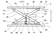
- FIG. 1 is a front view of a table lift device at a table lowering end
- FIG. 2 is a front view of the table lift device at a table rising end
- FIG. 3 is a right side view of FIG. It is.
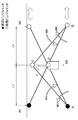
- FIG. 4 is a front view for explaining the relationship between the load acting on the panta arm and the lift arm at the table lowering end and the thrust of the electric cylinder 5
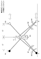
- FIG. 5 shows the load acting on the panta arm and the lift arm at the table raising end. It is a front view explaining the relationship of the thrust of an electric cylinder.
- the table lift device 10 includes a base 1 and a table 2, and includes two pantera arms 3A and 3B that are wide and narrow along the longitudinal direction of the base 1 and the table 2 between the base 1 and the table 2.
- Two lift arms 4A and 4B that move and bend in conjunction with the arms 3A and 3B are provided.
- the two panta arms 3A and 3B are provided in parallel.
- two lift arms 4A and 4B are also provided in parallel.
- the table lift device 10 has a motor 51, an electric cylinder 5, a drive shaft 53 of the electric cylinder, and a drive shaft 53 on the drive shaft 53 as a drive source for generating a thrust force for moving and bending the panta arms 3A, 3B and the lift arms 4A, 4B.
- a moving nut 52 that moves.
- panta arm 3A Next, the structure of the panta arms 3A and 3B will be described. Since the panta arm 3A and the panta arm 3B have the same structure, the panta arm 3A will be mainly described as an example.
- “outside” and “inside” refer to the center point (or center of gravity) of the base 1 and table 2 as the reference point, and the one closer to this reference point is referred to as “inside” and is farther away. Is called “outside”.
- the panta arm 3A includes an outer arm 31 and an inner arm 32.
- the outer arm 31 and the inner arm 32 cross each other in the vicinity of the center, and the crossing portions are rotatably connected by a center pin 61. Since the center pin 61 is commonly used in the panta arms 3A and 3B, the panta arms 3A and 3B move and bend in conjunction with each other.
- the lower end of the outer arm 31 is rotatably connected to the upper surface of the base 1 by a rotary shaft 72b and a base moving side rotary bearing 83.
- the base movement side rotary bearing 83 moves along the rail 85 fixed to the upper surface of the base 1 and along the wide and narrow direction of the pantera arm 3.
- the upper end of the outer arm 31 is rotatably connected to the lower surface of the table 2 by a rotary shaft 71a and a table fixed side rotary bearing 82.
- the table fixed side rotary bearing 82 is fixedly installed on the lower surface of the table 2 without moving in the wide and narrow direction of the panta arm 3A.
- the lower end portion of the inner arm 32 is fixedly connected to the upper surface of the base 1 via the rotary shaft 72a and the base fixed side rotary bearing 81, and fixedly moved without moving in the wide and narrow direction of the panta arm.
- the upper end portion of the inner arm 32 is rotatably connected to the table 2 via a rotary shaft 71b and a table moving side rotary bearing 84.
- the table moving side rotary bearing 84 is coupled so as to be movable along the rail 86 fixed to the lower surface of the table 2 and along the wide and narrow direction of the panta arm 3A.
- the configuration of the panta arm 3B is the same.
- the punter arms 3A and 3B are linked and widened by using the common rotating shafts 71a, 71b, 72a, and 72b.
- the lift arm 4A includes an inner arm 42 and an outer arm 41, and a connecting pin 62 that jointly connects the inner arm 42 and the outer arm 41 so as to be rotatable vertically above the center pin 61.
- the lengths of the inner arm 42 and the outer arm 41 of the lift arms 4A, 4B are configured to be longer than the length from the fulcrum of the outer arms 31, 32 of the panta arms 3A, 3B to the center pin 61.
- the lower end portion of the inner arm 42 of the lift arm 4A is rotatably connected to the base 1 by a rotary shaft 72a and a base fixed side rotary bearing 81.
- a lower end portion of the outer arm 41 is rotatably connected to the base 1 by a rotary shaft 72b and a base moving side rotary bearing 83.
- the upper end portion of the inner arm 42 and the upper end portion of the outer arm 41 are rotatably connected by a connecting pin 62.
- the drive source of this embodiment includes a motor 51, an electric cylinder 5 driven by the motor 51, a drive shaft 53 connected to the electric cylinder 5, and a moving nut 52 that moves on the drive shaft 53.
- the electric cylinder 5 is a so-called moving nut system in which the moving nut 52 moves on the driving shaft 53 by the rotation of the driving shaft 53 and a linear driving force is obtained by the thrust of the moving nut 52.
- an electric cylinder 5 of a type in which the drive shaft 53 is directly rotated by a worm reducer, for example, called a worm jack is used. Since the worm jack has the input shaft positioned in a direction perpendicular to the drive shaft 53, the drive motor 51 can be connected horizontally using a rotary joint or the like.
- the length in the drive axis direction (table minimum height) can be shortened.
- the moving nut type has the minimum length in the drive shaft direction.
- worm reduction gear not only the worm reduction gear but also a device whose input shafts are orthogonal, for example, a device using a bevel gear can be used.
- the electric cylinder 5 includes a rotary joint that connects the output shaft of the motor 51 and the input shaft of the electric cylinder 5, and a mechanism that transmits torque obtained from the input shaft to the drive shaft 53 and converts it into drive force (deceleration by a gear or the like).
- a rotation drive unit 57 that houses a mechanism). The rotation drive unit 57 is pin-joint connected to the center pin 61 of the panta arm 3A.
- the connecting pin 62 used in common for the lift arms 4A and 4B is connected to the moving nut 52 of the electric cylinder 5.
- the inner arm 42 of the lift arm 4A, the inner arm 32 of the panta arm 3A, and the drive shaft 53 of the electric cylinder 5 form a closed triangle (triangle ACD in FIGS. 4 and 5).
- the outer arm 41 of the lift arm 4A, the outer arm 31 of the panta arm 3A, and the drive shaft 53 of the electric cylinder 5 form a closed triangle (triangle BCD in FIGS. 4 and 5).
- the table 2 can be moved up and down by expanding and contracting the panta arm 3A in conjunction with the movement and bending of the outer arm 41 and the inner arm 42 of the lift arm 4A.
- FIG. 4 shows the state of the panta arm near the lower end of the table 2
- FIG. 5 shows the state of the punter arm near the upper end of the table.
- L1 in FIG. 4 and L2 in FIG. 5 are horizontal intervals between the fixed-side rotary bearing fulcrum A or the movable-side rotary bearing fulcrum B and the center pin fulcrum D of the panter arm.
- the structure in which the center pin 61 is lifted has the following advantages.
- the load distribution to the outer arm 31 and the inner arm 32 changes due to the movement of the applied position of the load load, and the deformation amount of the panta arms 3A and 3B changes.
- the load at the position of the center pin 61 is always the sum of the weights of the panter arms 3A and 3B and the driving source and the table load (W1 + W2 + W3). Always constant. Therefore, the moving nut 52 can be driven stably without being affected by the deformation of the outer arm 31 and the inner arm 32 caused by the change in the applied position of the load load, which is advantageous in extending the service life of the electric cylinder 5. become.
- the moving amount (stroke) of the moving nut 52 of the electric cylinder 5 is obviously smaller than the vertical moving amount of the table 2 and is the minimum compared with the other direction because it is a vertical movement. Therefore, the stroke of the drive unit can be shortened and the fluctuation in speed can be reduced, so that the table can be moved at a higher speed than in the prior art.
- the electric cylinder 5 particularly the worm jack type electric cylinder, is used as a driving source.
- a double-acting hydraulic pump or a chain-driven moving pulley mechanism is also used. Is possible.
- a DC brushless motor that can control the speed of the motor 51 that drives the electric cylinder 5, such as an inverter-controlled three-phase motor, a servo motor, or a speed setting with a constant output torque.
- the table lift device further includes control means (not shown) for controlling the motor speed (for example, hardware such as a central processing unit and a speed control program). Then, by controlling the speed of the motor by this control means, the elevation speed of the table 2 can be made variable. Accordingly, slow start or slow stop control can be performed in order to reduce the impact at the start or stop of the ascent. Further, the speed during the up-and-down movement can be kept constant or the up-and-down speed in an arbitrary range can be changed by setting the speed control program.
- the second embodiment is an embodiment in which the drive source of the table lift device of the first embodiment is changed to a drive source using a chain driven constant pulley mechanism, and the other configurations are the same as those of the first embodiment. is there.
- the lifting mechanism according to the second embodiment will be described with reference to FIG.
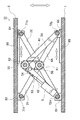
- FIG. 6 is a cross-sectional view in the front direction showing the table lift device at the table rising end in the second embodiment.
- the 6 includes an idler sprocket 55 on the outer arm 41 of the lift arm 4A and the connecting pin 62 of the inner arm 42. Further, the electric cylinder 5 can be rotated along the longitudinal direction of the inner arm 42 on or near the base fixed side rotary bearing 81 (hence the base fixed side rotating shaft 72) of the inner arm 42 of the lift arm 4A. Pin joint is supported.
- the electric cylinder 5 may be a standard one and can be longer than the worm jack as long as it can be stored in the longitudinal direction of the inner arm 42.
- the drive shaft 53 and the center pin 61 of the electric cylinder 5 are connected via an idler sprocket 55. More specifically, one end of the chain 54 is fixed near the open end of the drive shaft 53. Then, the chain 54 is sprinkled on the idler sprocket 55. Further, the other end of the chain 54 and the center pin 61 are fixed by pin joint connection.
- the lift arm 4A (and the lift arm 4B (not shown in FIG. 6) is not shown in the same manner as in the first embodiment.
- the outer arm 31 and the inner arm 32 are lifted with respect to, so that the panta arm 3A (and the punter arm 3B not shown in FIG. 6) extends, and the table 2 moves up and down.
- the chain 54 may be replaced with another member such as a wire or a timing belt as long as it has sufficient strength to withstand the tension.
- the third embodiment is an embodiment in which the drive source of the table lift device of the first embodiment is changed to a drive source using a chain drive moving pulley mechanism, and the other configurations are the same as those of the first embodiment. is there.
- the third embodiment will be described below based on FIG.
- FIG. 7 is a cross-sectional view in the front direction showing the table lift device at the table rising end in the third embodiment.
- the drive shaft 53 and the center pin 61 of the electric cylinder 5 are connected via idler sprockets 55 and 56. More specifically, one end of the chain 54 is fixed near the open end of the drive shaft 53. Then, the chain 54 is wound around the idler sprocket 55, and then the chain 54 is also wound around the idler sprocket 56. Then, the other end of the chain 54 and the vicinity of the connecting pin 62 in the inner arm 42 are fixed by pin joint connection.
- the idler sprocket 56 By driving the electric cylinder 5 and pulling the chain 54, the idler sprocket 56 having the center pin 61 as a rotation shaft operates as a moving pulley, so that the lift arm 4A (and illustrated in FIG. 7 is illustrated) as in the first embodiment.
- the outer arm 31 and the inner arm 32 are lifted with respect to the lift arm 4B), and the panta arm 3A (and the punter arm 3B not shown in FIG. 7) is extended, and the table 2 is raised and lowered.
- the chain 54 may be replaced with another member such as a wire or a timing belt as long as it has sufficient strength to withstand the tension.
- the stroke of the electric cylinder 5 is twice that of the first and second embodiments by using a moving pulley, but the required thrust is 1/2 that of the first and second embodiments. .
- the fourth embodiment is a modification of the first embodiment, and is an embodiment in which the position of the lift arm with respect to the punter arm in the first embodiment is switched up and down.
- the fourth embodiment will be described with reference to FIGS.
- FIG. 8 is a front view of the fourth embodiment when the positional relationship between the punter arm and the lift arm at the table lowering end is switched up and down.
- FIG. 9 is a front view of the fourth embodiment when the positional relationship between the panta arm and the lift arm at the table ascending end is switched up and down.
- the outer lift arm 41 and the inner lift arm 42 of the lift arm 4A are pin-jointed by a connecting pin 62 provided on the moving nut 52 of the electric cylinder 5 below the center pin 61. Further, the rotation drive unit 57 of the electric cylinder 5 is pin-joint connected to the center pin 61 of the panta arm 3A.
- the moving nut 52 is at a position closest to the release end of the drive shaft 53 (that is, the lowest position in the stroke of the moving nut 52).
- the connecting pin 62 connected to the moving nut 52 is also moved upward. Therefore, the lift arm 4A moves and bends, and in conjunction with this, the punter arm 3A extends. Thereby, the table 2 can be raised (FIG. 9).
- the load and required thrust of the table lift device according to the fourth embodiment are the same as those in the first embodiment.
- the fifth embodiment is a modification of the first embodiment, and in the first embodiment, the rotary bearing positions of the panta arm and the lift arm are made to coincide with each other.
- This is an embodiment in which a fulcrum and a fulcrum in a rotary bearing of a lift arm are installed at a certain distance.
- FIG. 10 is a front view of the fifth embodiment when the bearing positions of the panta arm and the lift arm at the table lower end are separated.
- FIG. 11 is a front view of the fifth embodiment when the bearing positions of the panta arm and the lift arm at the table ascending end are separated.
- the outer arm 41 of the lift arm 4A is rotatably connected to the base fixed side rotary bearing 81 via the base lift arm rotating shaft 72L.
- the inner arm 32 of the punter arm 3A is rotatably connected to the base fixed side rotary bearing 81 via a base panter arm rotating shaft 72P.
- the inner arm 42 of the lift arm 4A is rotatably connected to the base movement side rotary bearing 83 via the base lift arm rotating shaft 72L.
- the outer arm 31 of the punter arm 3A is rotatably connected to the base moving side rotary bearing 83 via the base panter arm rotating shaft 72P.
- the outer arm 41 and the inner arm of the lift arm 4A are made equal by making the distance between the fulcrum points of the panta arm 3A and the lift arm 4A on the base fixed side rotary bearing 81 and the base moving side rotary bearing 83 equal. Since the left and right symmetrical positional relationship between 42 and the outer arm 31 and the inner arm 32 of the panta arm 3A is maintained, the panta arm 3A can be lifted vertically with respect to the lift arm 4A.
- FIG. 12 is related to the sixth embodiment
- FIG. 12 (a) is a front view showing the panta arm and the lift arm at the table ascending end
- FIG. 12 (b) is the panter arm and the lift arm at the table descending end
- FIG. 13 (a) is a front view showing the load applied to the panter arm and the lift arm at the table rising end
- FIG. 13 (b) is the load related to the panter arm and the lift arm at the table descending end. It is a front view which shows the relationship between a load and thrust.
- the lift arm 4C includes an arm 43 and a connecting pin 63 that jointly connects the arm 43 so as to be rotatable vertically above the center pin 61.
- the length of the arm 43 of the lift arm 4C is configured to be longer than the length from the fulcrum of the outer arms 31 and 32 of the panta arm 3A to the center pin 61.
- the lower end portion of the arm 43 of the lift arm 4C is connected to the base via a rotary bearing (not shown) while being connected to the inner arm 32 by a common rotating shaft 74.
- the upper end portion of the arm 43 is connected to the moving nut 52 and the connecting pin 63.
- L2 in FIG. 13 (a) is a horizontal interval between the fixed rotation bearing fulcrum A or the movable rotation bearing fulcrum B of the panter arm at the rising end and the center pin fulcrum C
- L1 in FIG. 13 (b) is This is the horizontal distance between the fixed-side rotary bearing fulcrum A or the moving-side rotary bearing fulcrum B of the panter arm and the center pin fulcrum C at the lower end (L2 ⁇ L1).
- W1 is the load applied to the fixed side rotary bearing fulcrum A
- W2 is the load applied to the moving side rotary bearing fulcrum B
- W3 is the weight of the outer arm 31 and the inner arm 32 acting on the center pin fulcrum D
- F is a necessary thrust of the electric cylinder 5.
- M2 (W1 + W2 + W3) ⁇ L1 ⁇ ⁇ ⁇ ⁇ (9)
- W ⁇ L1 (W1 + W2 + W3) ⁇ L1 ⁇ ⁇ ⁇ (10)
- M3 F ⁇ L1 ⁇ ⁇ ⁇ (11)
- From M1 + M2 M3, 2 ⁇ (W1 + W2 + W3)
- ⁇ L1 F ⁇ L1 ⁇ ⁇ ⁇ (12)
- ⁇ F 2 (W1 + W2 + W3) Therefore, the thrust is twice the load acting on the center pin, and the thrust is larger than those in the first to fifth embodiments.
- the conventional example still requires a thrust several
- the outer arm and the inner arm of the panta arm and the lift arm may be interchanged, or the number of the panta arm and the lift arm may be changed.
- the position where the lift arm is provided may be opposite to the center pin.
- a support member that moves and / or bends in conjunction with the panter arm and traverses substantially vertically above the center pin may be used instead of the lift arm.
- the shape and structure of the center pin is not limited as long as it is capable of moving up and down with a thrust equivalent to the load on the center pin by applying thrust to the center pin directly or indirectly in a substantially vertical direction. It is included in the present invention.
- the lower end of the outer arm 31 of the substantially X-shaped panter arm is connected to the base moving side rotary bearing 83, the upper end is connected to the table fixed side rotary bearing 82, and the lower end of the inner arm 32 is connected to the base.
- the upper end of the base fixed side rotary bearing 81 is fixed to the table moving side rotary bearing 84, but the connection between the arm part connecting the base 1 and the table 2 to the base 1 and the table 2 is in the above connection form. Not exclusively.
- all the end portions of the outer arm 31 and the inner arm 32 may be connected to the base 1 and the table 2 using the moving-side rotary bearing, and among the four end portions, Only one of them may be connected by a fixed side rotating bearing, and the remaining three ends may be connected by a moving side rotating bearing.
- the shape is not limited to this shape, and the crossing point where the two arms are crossed is moved while restricting the moving direction in the vertical direction with respect to the base.
- the moving direction restricting member here is, for example, the drive shaft 53 with the thread groove cut in the above embodiment, the motor 51 for rotating the drive shaft 53, and the moving nut 52 connected to the crossing point.
- the drive shaft 53 has a length substantially the same as the moving range of the moving nut 52, that is, the moving range of the fulcrum, so that the stroke required for moving can be minimized.
- the movement direction restricting member is fixed to the arm portion, it moves as the arm portion and the fulcrum move up and down, so a fixing member to the base 1 becomes unnecessary, and the minimum height corresponding to the fixing member is eliminated. Can be suppressed.
- the table lift device can be applied to a bed device used in a medical device.
- the table lift device may be stored inside a medical image photographing bed, a top plate on which the subject is placed may be fixed on the table, and the top plate may be moved up and down.
- the table may be replaced with a top plate, and a panter arm may be connected to the back surface of the top plate via a fixed side rotary bearing and a movable side rotary bearing, and the top plate may be moved up and down.
- the medical device is not limited to a medical image photographing device, but may be an examination table on which the top plate moves up and down.
- the table lift device according to the present invention is not limited to the medical field, and can be applied to any device that needs to move the table up and down.
Landscapes
- Health & Medical Sciences (AREA)
- Life Sciences & Earth Sciences (AREA)
- Engineering & Computer Science (AREA)
- Public Health (AREA)
- Structural Engineering (AREA)
- Mechanical Engineering (AREA)
- Animal Behavior & Ethology (AREA)
- General Health & Medical Sciences (AREA)
- Geology (AREA)
- Veterinary Medicine (AREA)
- Nursing (AREA)
- Biomedical Technology (AREA)
- Accommodation For Nursing Or Treatment Tables (AREA)
- Invalid Beds And Related Equipment (AREA)
Abstract
Description
第一実施形態について図を用いて説明する。図1は本発明の第一実施形態に関し、テーブル下降端におけるテーブルリフト装置の正面図であり、図2はテーブル上昇端におけるテーブルリフト装置の正面図であり、図3は図2の右側面図である。
テーブルリフト装置10は、基台1とテーブル2とを備え、基台1とテーブル2との間に基台1とテーブル2の長手方向に沿って広狭する二つのパンタアーム3A、3Bと、パンタアーム3A、3Bに連動して移動及び屈曲する二つのリフトアーム4A、4Bとを備える。二つのパンタアーム3A、3Bは平行に備えられる。同様に、二つのリフトアーム4A、4Bも平行に備えられる。更にテーブルリフト装置10は、パンタアーム3A、3B及びリフトアーム4A、4Bを移動及び屈曲させる推力を発生させる駆動源として、モータ51と電動シリンダ5と電動シリンダの駆動軸53と駆動軸53上を移動する移動ナット52とを備える。
次にパンタアーム3A、3Bの構造について説明する。パンタアーム3Aとパンタアーム3Bとは、同一の構造であるため、主に、パンタアーム3Aを例に説明する。なお、以下の説明において用いる「外側」「内側」とは、基台1及びテーブル2の中心点(または重心点)を基準点とし、この基準点により近い方を「内側」と称し、より遠い方を「外側」と称したものである。
次にリフトアーム4A、4Bの構造について説明する。リフトアーム4Aとリフトアーム4Bとは、同一の構造であるため、主に、リフトアーム4Aを例に説明する。
次に駆動源について説明する。本実施形態の駆動源は、モータ51と、モータ51により駆動される電動シリンダ5と、電動シリンダ5に接続された駆動軸53と、駆動軸53上を移動する移動ナット52とを備える。電動シリンダ5は、駆動軸53が回転することによって駆動軸53上を移動ナット52が移動し、移動ナット52の推力によって直線駆動力を得るもので、移動ナット方式と呼ばれるものである。
次に、第一実施形態に係るテーブルリフト装置10の動作について説明する。
リフトアーム4Aの内側アーム42と、パンタアーム3Aの内側アーム32と、電動シリンダ5の駆動軸53とは、閉じた三角形(図4および図5における三角形ACD)を構成する。同様に、リフトアーム4Aの外側アーム41と、パンタアーム3Aの外側アーム31と、電動シリンダ5の駆動軸53とは、閉じた三角形(図4および図5における三角形BCD)を構成する。
次に図4と図5を用いて、パンタアーム及びリフトアームに作用する荷重と電動シリンダ5の推力Fの関係を説明する。図4は、テーブル2の下降端付近におけるパンタアームの状態を示し、図5は、テーブルの上昇端付近におけるパンタアームの状態を示している。図4のL1、図5のL2はパンタアームの固定側回転軸受支点Aまたは移動側回転軸受支点Bと、センターピン支点Dの間の水平方向間隔である。W1は固定側回転軸受支点Aに作用する負荷荷重、W2は移動側回転軸受支点Bに作用する負荷荷重、W3はセンターピン支点Dに作用するX字状外側アーム31、32と駆動源の重量(各回転軸受および移動部の摩擦抵抗なども含む)である。Fは電動シリンダ5の必要推力である。
W=W1+W2+W3・・・・(1)
と表すことができる。M1およびM2はセンターピン61に作用する荷重によって外側アーム31、32に作用するモーメントであり、図4の場合、
M1=M2=W・L1=(W1+W2+W3)・L1・・・(2)
と表すことができる。
M3=M4=F・L1・・・(3)
と表すことができる。
M1+M2=M3+M4・・・(4)
式(4)に式(2)(3)を代入すると
2×(W1+W2+W3)・L1=2×F・L1・・・(5)
となり、次の式(6)
F=W1+W2+W3・・・(6)
となる。よって、図4と図5いずれの場合も必要推力Fは、式(6)で表すことができるので、必要推力はテーブル2の上下動位置にかかわらず常に一定で、センターピン61に作用する荷重に等しくなる。
まず、テーブル2上で負荷荷重により、外側アーム31及び内側アーム32にはモーメントによる変形が生じる。テーブル2上で負荷荷重の作用位置が移動する場合、負荷荷重の作用位置の移動によって外側アーム31及び内側アーム32への荷重分布が変化し、パンタアーム3A、3Bの変形量が変化する。これに対し、センターピン61位置の負荷荷重は、必ずパンタアーム3A、3B及び駆動源の重量とテーブル負荷荷重との和(W1+W2+W3)となるので、常に一定荷重であり、センターピン61の変形は常に一定である。したがって負荷荷重の作用位置の変化によって生じる外側アーム31及び内側アーム32の変形の影響を受けることなく、安定して移動ナット52を駆動することができ、電動シリンダ5の使用寿命を延ばす上で有利になる。
第二実施形態は、第一実施形態のテーブルリフト装置の駆動源を、チェーン駆動の定滑車機構を用いた駆動源に変更した実施形態であって、その他の構成は第一実施形態と同様である。以下、図6に基づいて第二実施形態に係る昇降機構について説明する。図6は、第二実施形態に関し、テーブル上昇端におけるテーブルリフト装置を示す正面方向の断面図である。
第三実施形態は、第一実施形態のテーブルリフト装置の駆動源を、チェーン駆動の動滑車機構を用いた駆動源に変更した実施形態であって、その他の構成は第一実施形態と同様である。以下、図7に基づいて、第三実施形態について説明する。図7は第三実施形態に関し、テーブル上昇端におけるテーブルリフト装置を示す正面方向の断面図を示す。
第四実施形態は、第一実施形態の変形例であって、第一実施形態におけるパンタアームに対するリフトアームの位置を上下入れ替えた実施形態である。以下、第四実施形態について、図8及び図9に基づき説明する。図8は、第四実施形態に関し、テーブル下降端におけるパンタアーム及びリフトアームの位置関係を上下入れ替えた場合の正面図である。同様に図9は、第四実施形態に関し、テーブル上昇端におけるパンタアーム及びリフトアームの位置関係を上下入れ替えた場合の正面図である。
第五実施形態は、第一実施形態の変形例であって、第一実施形態ではパンタアーム及びリフトアームの回転軸受位置を一致させたのに対し、本実施形態では、パンタアームの回転軸受における支点とリフトアームの回転軸受における支点とを、一定距離をおいて設置した実施形態である。
第六実施形態は、第一実施形態のリフトアームを、1本のアーム43からなるリフトアーム4Cに置き換えた実施形態である。以下図12、図13に基づいて説明する。図12は第六実施形態に関し、図12(a)は、テーブル上昇端におけるパンタアームとリフトアームとを示す正面図であり、図12(b)は、テーブル下降端におけるパンタアームとリフトアームとを示す正面図である。また、図13(a)は、テーブル上昇端におけるパンタアームとリフトアームとに係る負荷荷重を示す正面図であり、図13(b)は、テーブル下降端におけるパンタアームとリフトアームとに係る負荷荷重及び推力の関係を示す正面図である。
第六実施形態において用いられるリフトアーム4Cの構造について説明する。リフトアーム4Cは、アーム43と、アーム43をセンターピン61の垂直上方で回転可能にジョイント接続する連結ピン63とを備えて構成される。リフトアーム4Cのアーム43の長さは、パンタアーム3Aの外側アーム31、32の支点からセンターピン61までの長さよりも長く構成される。
次に図13(a)、図13(b)を用いて、外側アーム31、32及びリフトアーム4Cのアーム43に作用する荷重と電動シリンダ5の推力Fの関係を説明する。図13(a)のL2は、上昇端におけるパンタアームの固定側回転軸受支点Aまたは移動側回転軸受支点Bと、センターピン支点Cとの間の水平方向間隔、図13(b)のL1は下降端におけるパンタアームの固定側回転軸受支点Aまたは移動側回転軸受支点Bと、センターピン支点Cとの間の水平方向間隔である(L2<L1)。W1は固定側回転軸受支点Aに作用する負荷荷重、W2は移動側回転軸受支点Bに作用する負荷荷重、W3はセンターピン支点Dに作用する外側アーム31及び内側アーム32と駆動部5の重量(各回転軸受および移動部の摩擦抵抗なども含む)である。Fは電動シリンダ5の必要推力である。
W=W1+W2+W3・・・・(7)
と表すことができる。M1およびM2はセンターピン61に作用する荷重によって外側アーム31、32に作用するモーメントであり、図13(b)の場合、
M1=(W1+W2+W3)・L1・・・・(8)
M2=(W1+W2+W3)・L1・・・・(9)
W・L1=(W1+W2+W3)・L1・・・(10)
M3=F・L1・・・・(11)
M1+M2=M3より、
2×(W1+W2+W3)・L1=F・L1・・・・(12)
∴ F=2(W1+W2+W3)
よって、推力はセンターピンに作用する荷重の2倍となり、上記第一実施形態から第五実施形態と比べて推力がより大きくなるが、それでもなお、従来例が荷重の数倍の推力を必要としていたのに比べて、必要推力をより小さくすることができる。
により接続してもよい。
Claims (11)
- 基台とテーブルとの間に略X字状のパンタアームを備え、そのパンタアームを伸縮させることにより前記テーブルを昇降動させる昇降機構であって、
前記パンタアームは、第一アーム及び第二アームと、それら第一アーム及び第二アームが交叉する部位を回転可能に連結したセンターピンと、を備え、
前記第一アームの一端部は、前記基台に固定された基台固定側回転軸受に回転可能に連結され、前記第一アームの他端部は、前記テーブルの下面を前記パンタアームの広狭方向に沿って移動可能なテーブル移動側回転軸受に回転可能に連結され、
前記第二アームの一端部は、前記テーブルに固定されたテーブル固定側回転軸受に回転可能に連結され、前記第二アームの他端部は、前記基台の上面を前記広狭方向に沿って移動可能な基台移動側回転軸受に回転可能に連結され、
前記昇降機構は、
前記パンタアームに連動して移動及び屈曲する支持部材であって、前記センターピンを通る略垂直線上を横断する支持部材と、
前記支持部材における前記略垂直線との交点と前記センターピンとを垂直方向に相対移動させる駆動源と、を備え、
前記相対移動に連動して前記センターピンが略垂直方向へ引き上げ及び引き下げられることにより前記パンタアームが伸縮し、この伸縮に連動して前記テーブルが昇降動する、ことを特徴とする昇降機構。 - 前記駆動源は、前記センターピン又は前記交点又に対し、前記センターピン又は前記交点の負荷荷重とほぼ同じ大きさの推力を加える、
ことを特徴とする請求項1に記載の昇降機構。 - 前記支持部材は、前記第一アームにおける前記基台固定側回転軸受から前記センターピンまでの長さよりも長い第三アーム及び第四アームと、それら第三アーム及び第四アームを回転可能に連結した連結ピンと、を備えたリフトアームであって、
前記第三アームの一端部は、前記基台固定側回転軸受に回転可能に連結され、
前記第四アームの一端部は、前記基台移動側回転軸受に回転可能に連結され、
前記連結ピンは、前記第三アームの他端部と前記第四アームの他端部とを、前記略垂直
線上かつ前記センターピンよりも上方において連結し、
前記駆動源は、前記連結ピンと前記センターピンとを垂直方向に相対移動させる、
ことを特徴とする請求項1に記載の昇降機構。 - 前記駆動源は、モータと、該モータで駆動する電動シリンダと、該電動シリンダの駆動軸と、該駆動軸に沿って移動する移動ナットと、を備え、
前記電動シリンダは、前記センターピンに接続され、
前記駆動軸は、その軸方向が垂直方向と略平行になるように、かつ前記センターピンよりも上方に備えられ、
前記移動ナットは、前記連結ピンに接続され、
前記電動シリンダが前記移動ナットを上方へ移動させると、前記センターピンが前記連結ピンに対して相対的に引き上げられることにより前記パンタアームは伸張して前記テーブルが上昇し、前記移動ナットが下方へ移動すると、前記センターピンが前記連結ピンに対して相対的に引き下げられることにより前記パンタアームが収縮して前記テーブルが下降する、ことを特徴とする請求項3に記載の昇降機構。 - 前記駆動源は、モータと、該モータで駆動する電動シリンダと、該電動シリンダの駆動軸と、前記駆動軸に接続され、前記電動シリンダによる張力に耐えうる変形可能な長尺部材と、該長尺部材の走行方向を変更する第一スプロケットと、を備えて構成され、
前記電動シリンダは、前記駆動軸の軸方向が前記第三アーム又は前記第四アームの長手方向と略平行になるように前記第三アーム又は前記第四アームに接続され、
前記第一スプロケットは、前記リフトアームに前記連結ピンを回転軸として備えられ、
前記長尺部材の一端部は前記駆動軸に接続され、他端部は前記第一スプロケットを経由して前記センターピンに略垂直に接続され、
前記電動シリンダが前記長尺部材を引っ張ることにより、前記センターピンが略垂直方向に吊り上げられて前記パンタアームが伸張し、この伸張に連動して前記テーブルが上昇し、前記電動シリンダが前記長尺部材を緩めることにより、前記センターピンが略垂直に吊り下げられて前記パンタアームが収縮し、この収縮に連動して前記テーブルが下降する、ことを特徴とする請求項3に記載の昇降機構。 - 前記駆動源は、モータと、該モータで駆動する電動シリンダと、該電動シリンダの駆動軸と、前記駆動軸に接続され、前記電動シリンダによる張力に耐えうる変形可能な長尺部材と、該長尺部材の走行方向を変更する第一スプロケット及び第二スプロケットと、を備えて構成され、
前記電動シリンダは、前記駆動軸の軸方向が前記第三アーム又は前記第四アームの長手方向と略平行になるように前記第三アーム又は前記第四アームに接続され、
前記第一スプロケットは、前記リフトアームに前記連結ピンを回転軸として備えられ、
前記第二スプロケットは、前記パンタアームに前記センターピンを回転軸として備えられ、
前記長尺部材の一端部は前記駆動軸に接続され、他端部は前記第一スプロケットを経由し、更に前記第二スプロケットを経由して前記電動シリンダが接続された前記第三アーム又は前記第四アームの前記連結ピン近傍の部位に接続され、
前記電動シリンダが前記長尺部材引っ張ると、前記センターピンが略垂直方向に吊り上げられて前記パンタアームが伸張し、この伸張に連動して前記テーブルが上昇し、前記電動シリンダが前記長尺部材を緩めると、前記センターピンを略垂直に吊り下げて前記パンタアームが収縮し、この収縮に連動して前記テーブルが下降する、ことを特徴とする請求項3に記載の昇降機構。 - 前記第三アームの前記基台固定側回転軸受における支点は、前記センターピンを中心として前記第一アームの前記基台固定側回転軸受における支点よりも外側に備えられ、
前記第四アームの前記基台移動側回転軸受における支点は、前記センターピンを中心として前記第二アームの前記基台移動側回転軸受における支点よりも外側に備えられる、ことを特徴とする請求項3に記載の昇降機構。 - 前記支持部材は、前記第一アームにおいて前記基台固定側回転軸受から前記センターピンまでの長さよりも短い第五アーム及び第六アームと、それら第五アーム及び第六アームを回転可能に連結した連結ピンと、を備えたリフトアームであって、
前記駆動源は、モータと、該モータで駆動する電動シリンダと、該電動シリンダの駆動軸と、該駆動軸に沿って移動する移動ナットと、を備え、
前記第五アームの一端部は、前記基台固定側回転軸受に回転可能に連結され、
前記第六アームの一端部は、前記基台移動側回転軸受に回転可能に連結され、
前記連結ピンは、前記第五アームの他端部と前記第六アームの他端部とを、前記略垂直線上かつ前記センターピンよりも下方において連結し、
前記電動シリンダは、前記センターピンに接続され、
前記駆動軸は、その軸方向が垂直方向と略平行になるように、かつ、前記センターピンよりも下方に設置され、
前記移動ナットは、前記連結ピンに接続され、
前記電動シリンダが前記移動ナットを上方へ移動させると、前記連結ピンが前記センターピンに対して相対的に引き上げられて前記パンタアームが伸張し、この伸張に連動して前記テーブルが上昇し、前記電動シリンダが前記移動ナットを下方へ移動させると、前記連結ピンが前記センターピンに対して相対的に引き下げられて前記パンタアームが収縮し、この収縮に連動して前記テーブルが下降する、ことを特徴とする請求項1に記載の昇降機構。 - 前記駆動源は、速度制御可能なモータを用いて構成され、
前記昇降機構は、前記モータの速度を可変制御することにより、前記テーブルの昇降速度を可変制御する制御手段を備える、
ことを特徴とする請求項1に記載の昇降機構。 - 基台とテーブルとの間に位置し、二本のアームを交叉させ、その交叉点を軸止した支点を備え、その支点の前記基台に対して略垂直方向に沿った移動に伴って前記テーブルを昇降動するアーム部と、
前記略垂直方向に沿った移動方向を規制しながら、前記支点を移動させる移動方向規制部材と、を備えたことを特徴とする昇降機構。 - 請求項1乃至10のいずれか一項に記載の昇降機構と、
被検体を載置する天板と、を備え、
前記天板を前記昇降機構により昇降動させる、
ことを特徴とする医用寝台装置。
Priority Applications (2)
| Application Number | Priority Date | Filing Date | Title |
|---|---|---|---|
| JP2011501556A JPWO2010098232A1 (ja) | 2009-02-24 | 2010-02-16 | 昇降機構及び医用寝台装置 |
| CN2010800050049A CN102292278A (zh) | 2009-02-24 | 2010-02-16 | 升降机构以及医用床位装置 |
Applications Claiming Priority (2)
| Application Number | Priority Date | Filing Date | Title |
|---|---|---|---|
| JP2009040560 | 2009-02-24 | ||
| JP2009-040560 | 2009-02-24 |
Publications (1)
| Publication Number | Publication Date |
|---|---|
| WO2010098232A1 true WO2010098232A1 (ja) | 2010-09-02 |
Family
ID=42665441
Family Applications (1)
| Application Number | Title | Priority Date | Filing Date |
|---|---|---|---|
| PCT/JP2010/052262 Ceased WO2010098232A1 (ja) | 2009-02-24 | 2010-02-16 | 昇降機構及び医用寝台装置 |
Country Status (3)
| Country | Link |
|---|---|
| JP (1) | JPWO2010098232A1 (ja) |
| CN (1) | CN102292278A (ja) |
| WO (1) | WO2010098232A1 (ja) |
Cited By (12)
| Publication number | Priority date | Publication date | Assignee | Title |
|---|---|---|---|---|
| CN102020220A (zh) * | 2010-12-20 | 2011-04-20 | 大连四达高技术发展有限公司 | 剪式升降平台 |
| WO2014156680A1 (ja) * | 2013-03-29 | 2014-10-02 | 株式会社 日立メディコ | 寝台を備えた医用画像撮影システムおよびその異常診断方法 |
| WO2016053210A1 (en) * | 2014-10-03 | 2016-04-07 | Srisawat Engineering Co., Ltd. | A vertically lifting device |
| CN106137656A (zh) * | 2016-08-17 | 2016-11-23 | 叶青 | 一种方便诊疗的诊疗台 |
| JP2017002531A (ja) * | 2015-06-09 | 2017-01-05 | 株式会社ハマネツ | ユニットトイレ |
| IT201800010183A1 (it) * | 2018-11-08 | 2020-05-08 | Cif Service S R L | Piattaforma elevatrice |
| EP3871564A1 (fr) | 2020-02-27 | 2021-09-01 | La Roche | Dispositif de relevage vertical de lit |
| CN113440161A (zh) * | 2021-07-20 | 2021-09-28 | 江苏斯坦德利医疗科技有限公司 | 一种可升降倾斜的床 |
| CN113560925A (zh) * | 2021-08-19 | 2021-10-29 | 沈阳飞机工业(集团)有限公司 | 大行程自适应双向压紧装置 |
| CN114569320A (zh) * | 2020-11-30 | 2022-06-03 | 喜来健株式会社 | 按摩装置 |
| CN115818501A (zh) * | 2022-12-15 | 2023-03-21 | 苏州市天烨医疗设备有限公司 | 一种医用单起升臂升降模块 |
| KR20250084409A (ko) | 2023-12-04 | 2025-06-11 | 주식회사 리워크 | 욕창 예방 전동 침대를 이용한 욕창 방지 시스템 |
Families Citing this family (9)
| Publication number | Priority date | Publication date | Assignee | Title |
|---|---|---|---|---|
| CN102743187B (zh) * | 2012-07-16 | 2014-04-30 | 上海联影医疗科技有限公司 | 一种具有保护装置的检查床 |
| CN104176675B (zh) * | 2013-10-30 | 2015-06-10 | 上海联影医疗科技有限公司 | 一种伸缩式支撑结构和病床升降机构 |
| CN104739613B (zh) * | 2013-12-31 | 2017-06-06 | 西门子(深圳)磁共振有限公司 | 一种病床以及医疗设备 |
| CN103979459B (zh) * | 2014-05-26 | 2016-05-18 | 黄卉 | 升降装置 |
| CN104739594A (zh) * | 2015-03-27 | 2015-07-01 | 苏州市天烨医疗设备有限公司 | 医用升降装置 |
| CN108099980B (zh) * | 2017-12-15 | 2020-04-07 | 常州工学院 | 一种双层平台多功能手推车 |
| CN110436379B (zh) * | 2019-08-14 | 2020-11-06 | 中南林业科技大学 | 一种剪叉式液压升降台 |
| CN115251892A (zh) * | 2022-08-22 | 2022-11-01 | 山东奥新医疗科技有限公司 | 一种磁共振扫描床 |
| CN116081518B (zh) * | 2023-02-07 | 2026-04-07 | 昆明昆船智慧机场技术有限公司 | 一种柔性驱动升降装置 |
Citations (3)
| Publication number | Priority date | Publication date | Assignee | Title |
|---|---|---|---|---|
| JPS4857067A (ja) * | 1971-11-08 | 1973-08-10 | ||
| JPS54100050A (en) * | 1978-01-24 | 1979-08-07 | Masao Akimoto | Lifter with auxiliary link |
| JPS60171996A (ja) * | 1984-02-13 | 1985-09-05 | 富士変速機株式会社 | テ−ブルリフト装置 |
Family Cites Families (3)
| Publication number | Priority date | Publication date | Assignee | Title |
|---|---|---|---|---|
| JPH0857067A (ja) * | 1994-08-23 | 1996-03-05 | Masahiko Sugimoto | 遠赤外線放射抗菌材 |
| JP2591598B2 (ja) * | 1995-02-14 | 1997-03-19 | 株式会社メイキコウ | テーブルリフト装置 |
| CN2687089Y (zh) * | 2004-03-11 | 2005-03-23 | 上海交通大学 | 铰接菱形多杆机构式升降装置 |
-
2010
- 2010-02-16 CN CN2010800050049A patent/CN102292278A/zh active Pending
- 2010-02-16 JP JP2011501556A patent/JPWO2010098232A1/ja active Pending
- 2010-02-16 WO PCT/JP2010/052262 patent/WO2010098232A1/ja not_active Ceased
Patent Citations (3)
| Publication number | Priority date | Publication date | Assignee | Title |
|---|---|---|---|---|
| JPS4857067A (ja) * | 1971-11-08 | 1973-08-10 | ||
| JPS54100050A (en) * | 1978-01-24 | 1979-08-07 | Masao Akimoto | Lifter with auxiliary link |
| JPS60171996A (ja) * | 1984-02-13 | 1985-09-05 | 富士変速機株式会社 | テ−ブルリフト装置 |
Cited By (16)
| Publication number | Priority date | Publication date | Assignee | Title |
|---|---|---|---|---|
| CN102020220A (zh) * | 2010-12-20 | 2011-04-20 | 大连四达高技术发展有限公司 | 剪式升降平台 |
| WO2014156680A1 (ja) * | 2013-03-29 | 2014-10-02 | 株式会社 日立メディコ | 寝台を備えた医用画像撮影システムおよびその異常診断方法 |
| US10258298B2 (en) | 2013-03-29 | 2019-04-16 | Hitachi, Ltd. | Medical image scanning system provided with bed and abnormality diagnosis method thereof |
| WO2016053210A1 (en) * | 2014-10-03 | 2016-04-07 | Srisawat Engineering Co., Ltd. | A vertically lifting device |
| JP2017002531A (ja) * | 2015-06-09 | 2017-01-05 | 株式会社ハマネツ | ユニットトイレ |
| CN106137656A (zh) * | 2016-08-17 | 2016-11-23 | 叶青 | 一种方便诊疗的诊疗台 |
| IT201800010183A1 (it) * | 2018-11-08 | 2020-05-08 | Cif Service S R L | Piattaforma elevatrice |
| FR3107645A1 (fr) | 2020-02-27 | 2021-09-03 | Sarl La Roche | Dispositif de relevage vertical de lit |
| EP3871564A1 (fr) | 2020-02-27 | 2021-09-01 | La Roche | Dispositif de relevage vertical de lit |
| CN114569320A (zh) * | 2020-11-30 | 2022-06-03 | 喜来健株式会社 | 按摩装置 |
| CN114569320B (zh) * | 2020-11-30 | 2024-04-05 | 喜来健株式会社 | 按摩装置 |
| US12364644B2 (en) | 2020-11-30 | 2025-07-22 | Ceragem Co., Ltd. | Massage apparatus |
| CN113440161A (zh) * | 2021-07-20 | 2021-09-28 | 江苏斯坦德利医疗科技有限公司 | 一种可升降倾斜的床 |
| CN113560925A (zh) * | 2021-08-19 | 2021-10-29 | 沈阳飞机工业(集团)有限公司 | 大行程自适应双向压紧装置 |
| CN115818501A (zh) * | 2022-12-15 | 2023-03-21 | 苏州市天烨医疗设备有限公司 | 一种医用单起升臂升降模块 |
| KR20250084409A (ko) | 2023-12-04 | 2025-06-11 | 주식회사 리워크 | 욕창 예방 전동 침대를 이용한 욕창 방지 시스템 |
Also Published As
| Publication number | Publication date |
|---|---|
| JPWO2010098232A1 (ja) | 2012-08-30 |
| CN102292278A (zh) | 2011-12-21 |
Similar Documents
| Publication | Publication Date | Title |
|---|---|---|
| WO2010098232A1 (ja) | 昇降機構及び医用寝台装置 | |
| JP6329336B2 (ja) | Xリンク式昇降機構 | |
| CN102482047B (zh) | 双层电梯 | |
| JP5644213B2 (ja) | 昇降装置 | |
| EP1881151B1 (en) | Drilling unit | |
| WO2017122475A1 (ja) | ゴンドラ装置 | |
| CN110294054B (zh) | 新型电动剪叉举升机构及自动导引运输车 | |
| CN1626005A (zh) | 升降装置以及使用该升降装置的升降床 | |
| CN105502213B (zh) | 变电设备顶升装置及其调整机构 | |
| CN113653376A (zh) | 一种舞台升降台 | |
| CN110181553B (zh) | 伸缩臂组件及造楼装置 | |
| JP4071521B2 (ja) | リフト装置 | |
| JP2591598B2 (ja) | テーブルリフト装置 | |
| JP2016013895A (ja) | リフター装置 | |
| JP7199433B2 (ja) | 推力昇降装置 | |
| CN114102661B (zh) | 一种双工作模式的高负载自重比的机械臂 | |
| EP4684691A1 (en) | Single-power-source lifting and folding mechanism and furniture | |
| US20050045428A1 (en) | Elevator with a scissor lift assembly and a central drive mechanism | |
| CN101432217A (zh) | 尤其用于小升降高度的升降台 | |
| CN212315360U (zh) | 模块化组装式吊装装置 | |
| JP2002320651A (ja) | 什器における昇降式脚部 | |
| KR101002944B1 (ko) | 텔레스코픽 타입의 로봇 | |
| JP7019382B2 (ja) | 昇降装置 | |
| CN106092616A (zh) | 车轮定位仪升降装置及车轮定位仪 | |
| CN101321680A (zh) | 电梯的悬吊装置 |
Legal Events
| Date | Code | Title | Description |
|---|---|---|---|
| WWE | Wipo information: entry into national phase |
Ref document number: 201080005004.9 Country of ref document: CN |
|
| 121 | Ep: the epo has been informed by wipo that ep was designated in this application |
Ref document number: 10746113 Country of ref document: EP Kind code of ref document: A1 |
|
| WWE | Wipo information: entry into national phase |
Ref document number: 2011501556 Country of ref document: JP |
|
| NENP | Non-entry into the national phase |
Ref country code: DE |
|
| 122 | Ep: pct application non-entry in european phase |
Ref document number: 10746113 Country of ref document: EP Kind code of ref document: A1 |