WO2010098087A1 - 携帯電子機器及びその制御方法 - Google Patents
携帯電子機器及びその制御方法 Download PDFInfo
- Publication number
- WO2010098087A1 WO2010098087A1 PCT/JP2010/001236 JP2010001236W WO2010098087A1 WO 2010098087 A1 WO2010098087 A1 WO 2010098087A1 JP 2010001236 W JP2010001236 W JP 2010001236W WO 2010098087 A1 WO2010098087 A1 WO 2010098087A1
- Authority
- WO
- WIPO (PCT)
- Prior art keywords
- key
- unit
- imaging instruction
- housing
- operation unit
- Prior art date
- Legal status (The legal status is an assumption and is not a legal conclusion. Google has not performed a legal analysis and makes no representation as to the accuracy of the status listed.)
- Ceased
Links
Images








Classifications
-
- H—ELECTRICITY
- H04—ELECTRIC COMMUNICATION TECHNIQUE
- H04M—TELEPHONIC COMMUNICATION
- H04M1/00—Substation equipment, e.g. for use by subscribers
- H04M1/72—Mobile telephones; Cordless telephones, i.e. devices for establishing wireless links to base stations without route selection
- H04M1/724—User interfaces specially adapted for cordless or mobile telephones
-
- H—ELECTRICITY
- H04—ELECTRIC COMMUNICATION TECHNIQUE
- H04M—TELEPHONIC COMMUNICATION
- H04M1/00—Substation equipment, e.g. for use by subscribers
- H04M1/72—Mobile telephones; Cordless telephones, i.e. devices for establishing wireless links to base stations without route selection
- H04M1/724—User interfaces specially adapted for cordless or mobile telephones
- H04M1/72466—User interfaces specially adapted for cordless or mobile telephones with selection means, e.g. keys, having functions defined by the mode or the status of the device
-
- H—ELECTRICITY
- H04—ELECTRIC COMMUNICATION TECHNIQUE
- H04N—PICTORIAL COMMUNICATION, e.g. TELEVISION
- H04N23/00—Cameras or camera modules comprising electronic image sensors; Control thereof
- H04N23/57—Mechanical or electrical details of cameras or camera modules specially adapted for being embedded in other devices
-
- H—ELECTRICITY
- H04—ELECTRIC COMMUNICATION TECHNIQUE
- H04N—PICTORIAL COMMUNICATION, e.g. TELEVISION
- H04N23/00—Cameras or camera modules comprising electronic image sensors; Control thereof
- H04N23/60—Control of cameras or camera modules
-
- G—PHYSICS
- G06—COMPUTING OR CALCULATING; COUNTING
- G06F—ELECTRIC DIGITAL DATA PROCESSING
- G06F1/00—Details not covered by groups G06F3/00 - G06F13/00 and G06F21/00
- G06F1/16—Constructional details or arrangements
- G06F1/1613—Constructional details or arrangements for portable computers
- G06F1/1615—Constructional details or arrangements for portable computers with several enclosures having relative motions, each enclosure supporting at least one I/O or computing function
- G06F1/1616—Constructional details or arrangements for portable computers with several enclosures having relative motions, each enclosure supporting at least one I/O or computing function with folding flat displays, e.g. laptop computers or notebooks having a clamshell configuration, with body parts pivoting to an open position around an axis parallel to the plane they define in closed position
-
- H—ELECTRICITY
- H04—ELECTRIC COMMUNICATION TECHNIQUE
- H04M—TELEPHONIC COMMUNICATION
- H04M2250/00—Details of telephonic subscriber devices
- H04M2250/12—Details of telephonic subscriber devices including a sensor for measuring a physical value, e.g. temperature or motion
-
- H—ELECTRICITY
- H04—ELECTRIC COMMUNICATION TECHNIQUE
- H04M—TELEPHONIC COMMUNICATION
- H04M2250/00—Details of telephonic subscriber devices
- H04M2250/52—Details of telephonic subscriber devices including functional features of a camera
Definitions
- the present invention relates to a portable electronic device having an imaging unit and a control method thereof.
- portable electronic devices such as cellular phones have been widely used that have an operation unit and an imaging unit.
- a portable electronic device including an operation unit having a plurality of keys and an imaging unit that performs imaging according to an imaging instruction by operating a predetermined key in the operation unit has been proposed (for example, , See Patent Document 1).
- a portable electronic device described in Patent Literature 1 includes an imaging unit that performs imaging in accordance with an imaging instruction, a blur amount detection unit that detects a blur amount of the imaging unit, an operation unit having a plurality of keys, and a plurality of keys.
- a key setting unit is provided that acquires a shake amount of the photographing unit by the shake amount detection unit every time any two or more keys are operated, and sets a key with a small amount of shake as a key for photographing instruction.
- an imaging instruction key for giving an imaging instruction by the imaging unit is set to a specific key in the operation unit and cannot be changed from the specific key. Therefore, the imaging instruction key may be difficult to operate depending on the attitude of the housing (for example, the tilt angle).
- An object of the present invention is to provide a portable electronic device capable of changing an imaging instruction key in accordance with a posture of a housing and a control method thereof.
- the portable electronic device includes a casing, an operation unit having a plurality of keys, a determination unit that acquires the attitude of the casing, and the operation according to the attitude of the casing acquired by the determination unit.
- a setting unit configured to set the predetermined key in the unit to an imaging instruction key for performing an imaging instruction, and an imaging unit configured to perform imaging in accordance with an imaging instruction by the imaging instruction key set by the setting unit.
- the portable electronic device further includes an inclination angle detection unit that detects an inclination angle of the housing with respect to a predetermined reference direction, and the determination unit corresponds to the inclination angle detected by the inclination angle detection unit. It is preferable to determine the attitude of the housing.
- the setting unit may include a first key of the predetermined keys when the tilt angle is approximately 90 degrees clockwise when the casing is viewed from a surface on which the operation unit is provided. Is set as the imaging instruction key, and the tilt angle when the casing is viewed from the surface on which the operation unit is provided is approximately 90 degrees counterclockwise, the It is preferable that a second key different from the first key is set as the imaging instruction key.
- the plurality of keys are arranged at a predetermined interval on one surface of the rectangular parallelepiped casing, and the first key and the second key are respectively positioned at corners of the one surface. It is preferable to do.
- a key set as the imaging instruction key is not provided on a side surface intersecting the one surface in the housing.
- the setting unit may include a third key among the predetermined keys when the tilt angle is approximately 45 degrees clockwise when the casing is viewed from the surface on which the operation unit is provided. Is set to the imaging instruction key, and when the tilt angle is approximately 45 degrees counterclockwise when the casing is viewed from the surface on which the operation unit is provided, It is preferable that a fourth key different from the third key is set as the imaging instruction key.
- the portable electronic device further includes a posture setting unit that sets a posture of the housing in advance, and the determination unit determines the posture of the housing according to the setting in the posture setting unit. .
- the portable electronic device further includes a display unit that displays a selection menu for selecting a direction of the casing when the imaging unit captures an image.
- the posture setting unit is selected by the selection menu. It is preferable to set the posture of the housing corresponding to the orientation.
- the housing includes a first housing, a second housing, and a connecting portion that connects the first housing and the second housing so as to be openable and closable. It is preferable that the predetermined key is set as the imaging instruction key in a state where the first housing and the second housing are opened to each other.
- the portable electronic device is configured to notify that the imaging instruction key is set when the notification unit performs notification in a predetermined mode and the setting unit sets the predetermined key as the imaging instruction key. It is preferable to further include a notification control unit that causes the unit to notify in the predetermined manner.
- the notification unit is a display unit, and the notification control unit displays the position of the imaging instruction key on the display unit as the predetermined mode.
- the notification unit is a backlight of the plurality of keys, and the notification control unit turns on the backlight of the predetermined key set in the imaging instruction key as the predetermined mode, or It is preferable that the backlight color of the predetermined key set as the imaging instruction key is changed.
- the predetermined key is an input operation key for inputting letters, numbers or symbols.
- the method for controlling a portable electronic device is a method for controlling a portable electronic device comprising a housing and an operation unit having a plurality of keys, the determination step for determining the attitude of the housing, and the determination A setting step of setting a predetermined key on the operation unit as an imaging instruction key for instructing imaging according to the posture of the casing determined by the step, and imaging by the imaging instruction key set by the setting step An imaging step of performing imaging in response to an instruction.
- the present invention it is possible to provide a portable electronic device that can change the imaging instruction key according to the attitude of the housing and a control method thereof.
- FIG. 4 is a perspective view of the cellular phone 1 in a closed state as viewed from the back surface 20B side of the operation unit side body 2.
- FIG. 3 is a block diagram showing functions of the mobile phone 1.
- FIG. It is a block diagram which shows the function of the mobile telephone 1 of 1st Embodiment. It is a figure which shows about the setting position of the attitude
- FIG. 6 is a flowchart illustrating an operation when imaging is performed by the camera 231 according to the mobile phone 1 of the first embodiment.
- FIG. 1 It is a block diagram which shows the function of the mobile telephone 1 of 2nd Embodiment. It is a figure which shows the specific example of the selection menu displayed on the display part 31 by the selection display part 455.
- FIG. It is a flowchart shown about operation
- FIG. 1 is a perspective view of a mobile phone 1 according to an embodiment of the present invention in an open state.
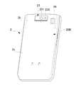
- FIG. 2 is a perspective view of the cellular phone 1 in the closed state as viewed from the back surface 20B side of the operation unit side body 2.
- FIG. 1 is a perspective view of a mobile phone 1 according to an embodiment of the present invention in an open state.
- FIG. 2 is a perspective view of the cellular phone 1 in the closed state as viewed from the back surface 20B side of the operation unit side body 2.
- FIG. 1 is a perspective view of a mobile phone 1 according to an embodiment of the present invention in an open state.
- FIG. 2 is a perspective view of the cellular phone 1 in the closed state as viewed from the back surface 20B side of the operation unit side body 2.
- FIG. 1 is a perspective view of a mobile phone 1 according to an embodiment of the present invention in an open state.
- FIG. 2 is a perspective view of the cellular phone 1 in the closed state as viewed from the back surface 20B
- the mobile phone 1 includes an operation unit side case (first case) 2, a display unit side case (second case) 3, an operation unit side case 2, and a display unit side case as the case. And a connecting portion 4 that connects the body 3.
- the operation unit side body 2 has a substantially rectangular parallelepiped shape with a small thickness, and constitutes a front case 2a constituting a front surface 20A as one surface and a back surface 20B.
- the rear case 2b and the battery cover 2c are mainly configured.
- a control unit 45 that controls various operations of the mobile phone 1
- a memory 44 that stores various types of information
- an acceleration sensor 46 all of which refer to FIG. 3
- a circuit board (not shown) on which electronic components are mounted is disposed.
- an operation unit 21 for performing a predetermined input operation and a microphone 22 are arranged on the front surface 20 ⁇ / b> A of the operation unit side body 2.
- the front surface 20 ⁇ / b> A is a surface that faces the display unit side body 3 in a state in which the cellular phone 1 is folded.
- the operation unit 21 has a plurality of keys.
- the operation unit 21 includes a function setting operation key 13 for operating various functions (applications) such as various settings, a phone book function, and a mail function, numbers of telephone numbers, characters such as mail, and symbols.
- Input operation keys 14 such as a numeric keypad and the like, and a determination operation key 15 for performing determination in various operations, scrolling in the vertical and horizontal directions, and the like.
- the function setting operation key 13, the input operation key 14, and the determination operation key 15 of the operation unit 21 are arranged on the front surface 20A of the operation unit side body 2 at predetermined intervals.
- Each key constituting the operation unit 21 is assigned a predetermined function in accordance with the open / closed state of the operation unit side body 2 and the display unit side body 3 and the type of the activated application (key / Assignment).
- each key constituting the operation unit 21 is pressed by the user, whereby an operation corresponding to the function assigned to each key is executed.
- the microphone 22 is used to input a voice uttered by the user of the mobile phone 1 during a call.
- a camera unit 23 and a speaker 24 as an audio output unit are arranged on the back surface 20B of the operation unit side body 2.
- the back surface 20B is a surface opposite to the front surface 20A.
- the side surface 20 ⁇ / b> C refers to a circumferential surface that intersects the front surface 20 ⁇ / b> A and the back surface 20 ⁇ / b> B of the operation unit side body 2.
- the camera unit 23 includes a camera (imaging unit) 231 and a light 232.
- the camera 231 is used to capture an image of a subject and acquire image information.
- the light 232 irradiates the subject imaged by the camera 231 with light.
- the speaker 24 outputs a sound for notifying the user of an incoming call to the mobile phone 1 or reception of an e-mail.
- the display unit side body 3 has a substantially rectangular parallelepiped shape with a small thickness, and includes a front case 3a and a front panel 3c that constitute the front surface 30A side, and a rear case that constitutes the rear side. 3b.
- a display unit 31 for displaying various kinds of information and a receiver 32 for outputting the voice of the other party of the call are arranged.
- the front surface 30 ⁇ / b> A is a surface facing the operation unit side body 2 in a state in which the cellular phone 1 is folded.
- the display unit 31 displays a standby image during communication and a call, an image based on an application for operating a predetermined function, and the like.
- the receiver 32 outputs the voice of the other party on the call. Note that the display unit 31 and the receiver 32 are arranged at positions that are hidden (positions that are not exposed) when the cellular phone 1 is closed.
- a sub-display unit (not shown) for displaying various information is arranged on the back surface of the display unit side body 3.
- the back surface is the surface opposite to the front surface 30A. That is, the sub display unit is disposed at a position exposed to the outside even when the cellular phone 1 is in the closed state.
- Each of the display unit 31 and the sub display unit arranged in the display unit side body 3 includes a liquid crystal panel, a drive circuit that drives the liquid crystal panel, and a light source unit such as a backlight that emits light from the back side of the liquid crystal panel. (Both not shown).
- the connection unit 4 connects the operation unit side body 2 and the display unit side body 3 so as to move relative to each other.
- the connecting portion 4 connects the upper end portion of the operation unit side body 2 and the lower end portion of the display unit side body 3.
- the mobile phone 1 relatively rotates the operation unit side body 2 and the display unit side body 3 connected via the connection unit 4, so that the operation unit side body 2 and the display unit side body 3 are rotated. Can be opened to each other (opened state), or the operation unit side body 2 and the display unit side body 3 can be folded (closed state).
- FIG. 3 is a block diagram showing functions of the mobile phone 1.
- the mobile phone 1 includes an operation unit 21, a microphone 22, a communication unit 41, an image processing unit 42, an audio processing unit 43, a memory 44, a control unit 45, an acceleration sensor 46, a vibrator 47, and a camera. 231 is provided in the operation unit side body 2.
- the mobile phone 1 includes a display unit 31, a receiver 32, and a driver IC 33 in the display unit side body 3.
- the communication unit 41 includes a main antenna 411 and an RF circuit unit 412.
- the communication unit 41 communicates with a predetermined communication destination. Examples of communication destinations with which the communication unit 41 communicates include an external terminal device that transmits / receives telephones and mails to / from the mobile phone 1 and an external device such as an external web server that connects the mobile phone 1 to the Internet.
- the main antenna 411 communicates with an external device in a predetermined use frequency band (for example, 800 MHz).
- the RF circuit unit 412 demodulates the signal received by the main antenna 411 and supplies the processed signal to the control unit 45.
- the RF circuit unit 412 modulates the signal supplied from the control unit 45 and transmits it to the external device (base station) via the main antenna 411.
- the image processing unit 42 performs predetermined image processing under the control of the control unit 45, and outputs the processed image data to the driver IC 33.
- the driver IC 33 stores the image data supplied from the image processing unit 42 in a frame memory (not shown) and outputs it to the display unit 31 at a predetermined timing.
- the sound processing unit 43 performs predetermined sound processing on the signal supplied from the RF circuit unit 412 under the control of the control unit 45 and outputs the processed signal to the receiver 32 and the speaker 24.
- the audio processing unit 43 processes the signal input from the microphone 22 under the control of the control unit 45 and outputs the processed signal to the RF circuit unit 412.
- the RF circuit unit 412 performs predetermined processing on the signal supplied from the sound processing unit 43 and outputs the processed signal to the main antenna 411.
- the receiver 32 and the speaker 24 output the signal supplied from the sound processing unit 43 to the outside under the control of the control unit 45.
- the memory 44 includes, for example, a working memory and is used for arithmetic processing by the control unit 45.
- the memory 44 stores data, tables, and the like used by various applications that operate on the mobile phone 1.
- the memory 44 may be a removable external memory.
- the control unit 45 controls the entire mobile phone 1 and performs predetermined control on the communication unit 41, the image processing unit 42, the display unit 31, the audio processing unit 43, the speaker 24, the receiver 32, the vibrator 47, and the like. Do. A specific configuration of the control unit 45 will be described later.
- the acceleration sensor 46 detects a change in the position of the operation unit side body 2 as an acceleration value and outputs the acceleration value to the control unit 45.
- the control unit 45 (an inclination angle detection unit 451 described later) detects the attitude of the operation unit side body 2 based on the acceleration value output by the acceleration sensor 46.
- the vibrator 47 is attached to the inside of the operation unit side body 2 and generates vibrations under the control of the control unit 45. When the vibration generated by the vibrator 47 is transmitted to the operation unit side body 2, the mobile phone 1 vibrates.
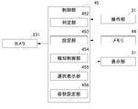
- FIG. 4 is a block diagram illustrating functions of the mobile phone 1 according to the first embodiment.
- the mobile phone 1 includes an acceleration sensor 46, a camera 231, an operation unit 21, a memory 44, and a control unit 45.
- the memory 44 stores the acceleration value output from the acceleration sensor 46, the inclination angle of the operation unit side body 2 corresponding to the acceleration value, and the attitude of the operation unit side case 2 corresponding to the inclination angle in association with each other. is doing.
- the control unit 45 includes an inclination angle detection unit 451, a determination unit 452, a setting unit 453, and a notification control unit 454.
- the inclination angle detection unit 451 detects the inclination angle of the operation unit side body 2 with respect to a predetermined reference direction. Specifically, when the acceleration is output from the acceleration sensor 46, the tilt angle detection unit 451 refers to the memory 44 and stores the operation unit side body 2 in association with the acceleration value output by the acceleration sensor 46. The actual inclination angle of the operation unit side body 2 is detected.
- the predetermined reference direction will be described later.
- the determination unit 452 determines the attitude of the operation unit side body 2. Specifically, the determination unit 452 determines the attitude of the operation unit side body 2 according to the inclination angle detected by the inclination angle detection unit 451. Specifically, the determination unit 452 determines the attitude of the operation unit side body 2 stored in the memory 44 in association with the inclination angle according to the inclination angle detected by the inclination angle detection unit 451.
- the setting unit 453 sets a predetermined key on the operation unit 21 as an imaging instruction key for performing an imaging instruction in accordance with the attitude of the operation unit side body 2 determined by the determination unit 452.
- the “imaging instruction key” is a key (shutter key) for instructing an imaging when the camera 231 performs imaging.
- the notification control unit 454 causes the notification unit to notify that the imaging instruction key has been set in a predetermined manner.
- the backlight of each key (not shown) in the display unit 31 and the operation unit 21 functions as a notification unit.
- a predetermined mode for example, the position of the imaging instruction key is displayed on the display unit 31.
- the backlight of the predetermined key set to the imaging instruction key is turned on. Examples include changing the color of the backlight.
- the camera 231 performs imaging in accordance with an imaging instruction with an imaging instruction key set by the setting unit 453.
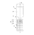
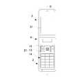
- FIGS. 5A to 5C show the posture of the operation unit side body 2 and the setting position of the imaging instruction key corresponding thereto when the operation unit side body 2 is inclined in a direction substantially orthogonal to the reference direction D. It is a figure shown about.
- FIG. 5A is a diagram illustrating a setting position of the imaging instruction key when the posture of the operation unit side body 2 is a direction substantially along the reference direction D.
- the “reference direction D” corresponds to a predetermined reference direction and refers to a direction serving as a reference for the attitude of the operation unit side body 2 in which the camera 231 is disposed.
- the reference direction D is a vertical direction, a horizontal direction, or the like.
- the “inclination angle of the operation unit side body 2” refers to the inclination angle of the operation unit side body 2 with respect to the reference direction D. For example, when the reference direction D is the vertical direction, the inclination angle is 0 degree when the longitudinal direction of the operation unit side body 2 is along the vertical direction.
- the setting unit 453 has a predetermined value in the operation unit 21 when the inclination angle ⁇ 0 when the operation unit side body 2 is viewed from the surface on which the operation unit 21 is provided is approximately 0 degrees.
- the determination operation key 15 is set as an imaging instruction key. That is, the setting unit 453 sets the determination operation key 15 as an imaging instruction key when the attitude of the operation unit side body 2 is a direction substantially along the reference direction D.
- the inclination angle ⁇ 0 is approximately 0 degrees” is a certain range including 0 degrees, and specifically, for example, the inclination angle ⁇ 0 with respect to the reference direction D is within a range of ⁇ 10 to 10 degrees. It means that.
- FIG. 5B shows the setting position of the imaging instruction key when the mobile phone 1 is rotated clockwise from FIG. 5A and the attitude of the operation unit side body 2 is inclined in a direction substantially orthogonal to the reference direction D.
- FIG. FIG. 5B shows the setting position of the imaging instruction key when the mobile phone 1 is rotated clockwise from FIG. 5A and the attitude of the operation unit side body 2 is inclined in a direction substantially orthogonal to the reference direction D.
- the setting unit 453 is configured to operate the operation unit 21 when the inclination angle ⁇ 1 when the operation unit side body 2 is viewed from the surface where the operation unit 21 is provided is approximately 90 degrees clockwise.
- the input operation key (first key) 14a among the predetermined keys is set as an imaging instruction key. That is, the setting unit 453 switches the imaging instruction key from the determination operation key 15 to the input operation key 14a.
- the inclination angle ⁇ 1 is approximately 90 degrees clockwise” is a certain range including 90 degrees. Specifically, for example, the inclination angle ⁇ 1 with respect to the reference direction D is 80 to 100 degrees clockwise. It is within the range.
- FIG. 5C shows the setting position of the imaging instruction key when the mobile phone 1 is rotated counterclockwise from FIG. 5A and the attitude of the operation unit side body 2 is tilted in a direction substantially orthogonal to the reference direction D.
- the setting unit 453 is configured so that when the operation unit side body 2 is viewed from the surface on which the operation unit 21 is provided, the inclination angle ⁇ 2 is approximately 90 degrees counterclockwise.
- An input operation key (second key) 14b that is different from the input operation key 14a among the predetermined keys in 21 is set as an imaging instruction key. That is, the setting unit 453 switches the imaging instruction key from the determination operation key 15 to the input operation key 14b.
- the inclination angle ⁇ 2 is approximately 90 degrees counterclockwise” is a certain range including 90 degrees. Specifically, for example, the inclination angle ⁇ 2 of the imaging direction D2 with respect to the reference direction D is counterclockwise. It is within the range of 80 to 100 degrees around.
- the input operation key 14a and the input operation key 14b set as the imaging instruction key by the setting unit 453 are positioned at the corners of the front surface 20A of the operation unit side body 2, respectively. .
- the key set as the imaging instruction key is not provided on the side surface 20C intersecting the front surface 20A (see FIGS. 1 and 2).
- FIGS. 6A to 6C show the posture of the operation unit side body 2 and the setting position of the imaging instruction key corresponding to the posture of the operation unit side body 2 when the operation unit side body 2 is inclined obliquely with respect to the reference direction D.
- FIG. 6A to 6C show the posture of the operation unit side body 2 and the setting position of the imaging instruction key corresponding to the posture of the operation unit side body 2 when the operation unit side body 2 is inclined obliquely with respect to the reference direction D.
- FIG. 6A is a diagram illustrating a setting position of the imaging instruction key when the attitude of the operation unit side body 2 is a direction substantially along the reference direction D, as in FIG. 5A described above.
- the setting unit 453 has a predetermined angle in the operation unit 21 when the inclination angle ⁇ 0 when the operation unit side body 2 is viewed from the surface on which the operation unit 21 is provided is approximately 0 degrees.
- the determination operation key 15 is set as an imaging instruction key.
- FIG. 6B is a diagram showing the setting position of the imaging instruction key when the mobile phone 1 is rotated clockwise from FIG. 6A and the posture of the operation unit side body 2 is inclined obliquely with respect to the reference direction D.
- FIG. is there.
- the setting unit 453 is configured to operate the operation unit 21 when the tilt angle ⁇ 3 when the operation unit side body 2 is viewed from the surface on which the operation unit 21 is provided is approximately 45 degrees clockwise.
- the input operation key (third key) 14c among the predetermined keys is set as an imaging instruction key. That is, the setting unit 453 switches the imaging instruction key from the determination operation key 15 to the input operation key 14c.
- the inclination angle ⁇ 3 is approximately 45 degrees clockwise” is a certain range including 45 degrees. Specifically, for example, the inclination angle ⁇ 3 of the imaging direction D2 with respect to the reference direction D is clockwise. It is within the range of 35 to 55 degrees.
- FIG. 6C is a diagram illustrating the setting position of the imaging instruction key when the mobile phone 1 is rotated counterclockwise from FIG. 6A and the attitude of the operation unit side body 2 is inclined obliquely with respect to the reference direction D.
- the setting unit 453 is configured so that when the operation unit side body 2 is viewed from the surface where the operation unit 21 is provided, the inclination angle ⁇ 4 is approximately 45 degrees counterclockwise.
- An input operation key (fourth key) 14d different from the input operation key 14c among the predetermined keys in 21 is set as an imaging instruction key. That is, the setting unit 453 switches the imaging instruction key from the determination operation key 15 to the input operation key 14d.
- the inclination angle ⁇ 4 is approximately 45 degrees counterclockwise” is a certain range including 45 degrees. Specifically, for example, the inclination angle ⁇ 4 with respect to the reference direction D is 35 to 50 degrees counterclockwise. It is within the range of 55 degrees.
- FIG. 7 is a flowchart illustrating an operation when imaging is performed by the camera 231 according to the mobile phone 1 of the first embodiment.
- step S1 the control unit 45 activates the camera 231 in response to a predetermined operation by the operation unit 21.
- the predetermined operation is, for example, pressing of a camera activation key for activating the camera 231 in the operation unit 21.
- step S2 the tilt angle detection unit 451 detects the tilt angle of the operation unit side body 2 with respect to the reference direction D.
- step S3 the determination unit 452 determines the attitude of the operation unit side body 2 according to the inclination angle detected by the inclination angle detection unit 451.
- step S4 the setting unit 453 sets a predetermined key on the operation unit 21 as an imaging instruction key for performing an imaging instruction in accordance with the attitude of the operation unit side body 2 determined by the determination unit 452.
- step S5 the notification control unit 454 causes the notification unit to notify the imaging instruction key set by the setting unit 453 in a predetermined manner.
- step S6 the control unit 45 determines whether or not the imaging instruction key set in step S4 has been pressed within a certain period. When the imaging instruction key is pressed (Yes), the process proceeds to step S7. On the other hand, when the imaging instruction key is not pressed (No), the process proceeds to step S2.
- step S7 the camera 231 captures an image of the subject in accordance with the imaging instruction using the imaging instruction key set in step S4.
- the mobile phone 1 includes an operation unit side body 2, an operation unit 21 having a plurality of keys, a determination unit 452 that determines the attitude of the operation unit side body 2, and an operation unit side case that is determined by the determination unit 452.
- a setting unit 453 that sets a predetermined key on the operation unit 21 according to the posture of the body 2 as an imaging instruction key for performing an imaging instruction, and performs imaging according to an imaging instruction by an imaging instruction key set by the setting unit 453 A camera 231.
- the mobile phone 1 sets a predetermined key as the imaging instruction key from the plurality of keys in the operation unit 21 by the setting unit 453 according to the attitude of the operation unit side body 2 determined by the determination unit 452. To do. Therefore, since the imaging instruction key is set at a position where the user can easily issue an imaging instruction according to the attitude of the operation unit side body 2, the cellular phone 1 can preferably perform imaging with the camera 231.
- the mobile phone 1 further includes an inclination angle detection unit 451 that detects an inclination angle of the operation unit side body 2 with respect to the reference direction D, and the determination unit 452 corresponds to the inclination angle detected by the inclination angle detection unit 451. Then, the attitude of the operation unit side body 2 is determined. Accordingly, the mobile phone 1 sets the posture of the operation unit side body 2 in accordance with the inclination angle detected by the inclination angle detection unit 451, and thus accurately detects and detects the posture of the operation unit side case 2.
- An imaging instruction key can be set according to the posture. Therefore, the mobile phone 1 can more suitably set the imaging instruction key.
- the inclination angle when the operation unit side body 2 is viewed from the surface on which the operation unit 21 is provided is approximately 90 degrees clockwise or approximately 90 degrees counterclockwise, the user can The four corners of the telephone 1 (the end on the side opposite to the connecting part 4 of the operation unit side body 2 and the end on the side opposite to the connecting part 4 of the display unit side body 3) are held and the camera 231 takes an image. This is often done (see FIGS. 5B and 5C).
- the setting unit 453 has an inclination angle ⁇ 1 of approximately 90 degrees clockwise when the operation unit side body 2 is viewed from the surface where the operation unit 21 is provided.
- the input operation key 14a among the predetermined keys in the operation unit 21 is set as an imaging instruction key.
- the setting unit 453 displays a predetermined key on the operation unit 21 when the inclination angle ⁇ 2 when viewing the operation unit side body 2 from the surface on which the operation unit 21 is provided is approximately 90 degrees counterclockwise.
- the input operation key 14b different from the input operation key 14a is set as the imaging instruction key.
- the imaging instruction key when the user is left-handed, the imaging instruction key can be set to the input operation key 14a, and when the user is right-handed, the imaging instruction key can be set to the input operation key 14b. Therefore, regardless of the user's dominant hand, the imaging instruction key can be set at a position where the user can easily give an imaging instruction according to the attitude of the operation unit side body 2.
- the input operation key 14a and the input operation key 14b set by the setting unit 453 are respectively positioned at the corners of the front surface 20A of the operation unit side body 2. . Accordingly, for example, when the user holds the four corners of the mobile phone 1 and performs imaging with the camera 231 (see FIGS. 5B and 5C), the attitude of the operation unit side body 2 regardless of the user's dominant hand. Accordingly, the imaging instruction key can be set at a position where the user can easily issue an imaging instruction.
- the operation unit side body 2 is not provided with a key set as an imaging instruction key on the side surface 20C intersecting the front surface 20A.
- the operation unit side body 2 and the display unit side body 3 are thin (for example, the operation unit side body 2 and the display unit side body 3 in the closed state). Even if the side key as the imaging instruction key cannot be provided on the side surfaces of the operation unit side body 2 and the display unit side body 3, the posture of the operation unit side body 2 is Accordingly, the imaging instruction key can be set at a position where the user can easily issue an imaging instruction.
- the setting unit 453 has an inclination angle ⁇ 3 of about 45 degrees clockwise when the operation unit side body 2 is viewed from the surface on which the operation unit 21 is provided. Is set, the input operation key 14c among the predetermined keys in the operation unit 21 is set as an imaging instruction key. Further, the setting unit 453 has a predetermined key on the operation unit 21 when the inclination angle ⁇ 4 when the operation unit side body 2 is viewed from the surface on which the operation unit 21 is provided is approximately 45 degrees counterclockwise. An input operation key 14d different from the input operation key 14c is set as an imaging instruction key.
- the user can set the imaging instruction key at a position where the user can easily perform the imaging instruction. .
- the setting unit 453 has a predetermined setting in the operation unit 21 in a state where the operation unit side body 2 and the display unit side body 3 are opened to each other (open state).
- Set the key to the imaging instruction key thereby, the user can suitably perform imaging by the camera 231 in the open state in which the operation unit side body 2 is easily inclined.
- the imaging instruction key is set.
- a notification control unit 454 that notifies the notification unit in a predetermined manner. Therefore, the user can recognize the position of the imaging instruction key by notification by the notification unit, and can preferably perform imaging by the camera 231.
- the mobile phone 1 according to the second embodiment has a point that the acceleration sensor 46 is not used, a tilt angle detection unit 451 is not provided, a configuration of the determination unit 452 is different, and a selection display unit 455 and a posture setting unit 456 are provided. Unlike the first embodiment, other configurations are the same as those of the first embodiment.
- the mobile phone 1 according to the second embodiment has a function of selecting the attitude of the operation unit side body 2 when imaging with the camera 231.
- FIG. 8 is a block diagram illustrating functions of the mobile phone 1 according to the second embodiment.
- the control unit 45 includes a determination unit 452, a setting unit 453, a notification control unit 454, a selection display unit 455, and an attitude setting unit 456.
- the setting unit 453 and the notification control unit 454 have the same functions as those in the first embodiment, and a description thereof will be omitted.
- the selection display unit 455 causes the display unit 31 to display a selection menu for selecting the direction of the operation unit side body 2 when the camera 231 takes an image.
- the posture setting unit 456 sets the posture of the operation unit side body 2 in advance. Specifically, the posture setting unit 456 sets a posture corresponding to the direction of the operation unit side body 2 selected from the selection menu.
- the determination unit 452 selects, from the selection menu displayed on the display unit 31 by the selection display unit 455, the posture of the operation unit side body 2 when the image is captured by the camera 231 according to the setting in the posture setting unit 456. Judge by.
- FIG. 9 is a diagram illustrating a specific example of a selection menu displayed on the display unit 31 by the selection display unit 455.
- the selection display unit 455 displays a message 310 and a selection menu 311 on the display unit 31 when the camera 231 is activated.
- the selection menu 311 includes menus 312 to 314.
- a message “Please determine the orientation for imaging” is displayed in order to alert the user of the attitude of the operation unit side body 2 when imaging.
- the menus 312 to 314 display messages corresponding to the attitude of the operation unit side body 2 respectively. That is, the menu 312 displays “vertical”, the menu 313 displays “right”, and the menu 314 displays “left”.
- “vertical orientation” corresponds to a case where the inclination angle ⁇ 0 when the operation unit side body 2 is viewed from the surface on which the operation unit 21 is provided is approximately 0 degrees (see FIG. 5A).
- “rightward” corresponds to the case where the inclination angle ⁇ 1 when the operation unit side body 2 is viewed from the surface on which the operation unit 21 is provided is approximately 90 degrees clockwise (see FIG. 5B).
- “leftward” corresponds to a case where the inclination angle ⁇ 2 when the operation unit side body 2 is viewed from the surface on which the operation unit 21 is provided is approximately 90 degrees counterclockwise (see FIG. 5C). .
- the determination unit 452 determines the attitude of the operation unit side body 2 by selecting any one of the selection menus 311 through a selection operation on the operation unit 21.
- FIG. 10 is a flowchart illustrating an operation when imaging is performed by the camera 231 according to the mobile phone 1 of the second embodiment.
- step S ⁇ b> 11 the control unit 45 activates the camera 231 in response to a predetermined operation by the operation unit 21.
- step S12 the selection display unit 455 displays a selection menu 311 (see FIG. 9) for selecting the attitude of the operation unit side body 2 on the display unit 31.
- step S13 the determination unit 452 selects any one selection menu from the selection menu 311. Then, the determination unit 452 determines the attitude of the operation unit side body 2 according to the selected selection menu.
- step S14 the setting unit 453 sets a predetermined key on the operation unit 21 as an imaging instruction key for performing an imaging instruction in accordance with the attitude of the operation unit side body 2 determined by the determination unit 452.
- step S15 the notification control unit 454 causes the notification unit to notify the imaging instruction key set by the setting unit 453 in a predetermined manner.
- step S16 the camera 231 captures an image of the subject according to the imaging instruction by the imaging instruction key set in step S14.
- the determination unit 452 determines the attitude of the operation unit side body 2 by selecting the attitude of the operation unit side body 2 when capturing an image with the camera 231 according to the setting in the attitude setting unit 456. Thereby, for example, even when the mobile phone 1 does not have the acceleration sensor 46, the determination unit 452 determines the posture of the operation unit side body 2 according to the posture of the operation unit side body 2.
- An imaging instruction key is set at a position where the user can easily issue an imaging instruction. Therefore, the user can preferably perform imaging with the camera 231.
- the operation unit side body 2 and the display unit side body 3 are thin (for example, the operation unit side body 2 and the display unit side in the closed state). This is particularly effective when the total thickness of the casing 3 is within 10 mm), and side keys as imaging instruction keys cannot be provided on the side surfaces of the operation unit side casing 2 and the display unit side casing 3.
- the tilt angle detection unit 451 is based on the acceleration value output by the acceleration sensor 46 and the tilt angle of the operation unit side body 2 stored in the memory 44 in association with the acceleration value.
- the present invention is not limited to this.
- the mobile phone 1 may detect the tilt angle of the operation unit side body 2 using an angle detection sensor.
- the reference direction D is the longitudinal direction of the operation unit side body 2, but the present invention is not limited to this.
- the mobile phone 1 may use a predetermined direction in the operation unit side body 2 and the display unit side body 3 as the reference direction D.
- the present invention is applied to the mobile phone 1 as a portable electronic device, but is not limited thereto. That is, the present invention may be applied to other portable electronic devices such as a personal digital assistant (PDA), a notebook computer, a digital camera, and a small audio player.
- PDA personal digital assistant
- notebook computer a notebook computer
- digital camera a digital camera
- small audio player a small audio player
Landscapes
- Engineering & Computer Science (AREA)
- Signal Processing (AREA)
- Multimedia (AREA)
- Human Computer Interaction (AREA)
- Computer Networks & Wireless Communication (AREA)
- Telephone Set Structure (AREA)
- Telephone Function (AREA)
- Studio Devices (AREA)
Abstract
筐体の姿勢に応じて撮像指示キーを変更できる携帯電子機器及びその制御方法を提供すること。 操作部側筐体と、複数のキーを有する操作部21と、操作部側筐体の姿勢を判定する判定部452と、判定部452により判定される操作部側筐体の姿勢に応じて操作部21における所定のキーを、撮像指示を行う撮像指示キーに設定する設定部453と、設定部453により設定される撮像指示キーによる撮像指示に応じて撮像を行うカメラ231とを備える。
Description
本発明は、撮像部を有する携帯電子機器及びその制御方法に関する。
従来より、携帯電話機等の携帯電子機器は、操作部及び撮像部を有するものが普及している。このような携帯電子機器として、複数のキーを有する操作部と、操作部における所定のキーの操作による撮像指示に応じて撮像を行う撮像部と、を備える携帯電子機器が提案されている(例えば、特許文献1参照)。
特許文献1に記載の携帯電子機器は、撮像指示に応じて撮像を行う撮像部と、撮像部のぶれ量を検出するぶれ量検出部と、複数のキーを有する操作部と、複数のキーのうちのいずれか2つ以上のキーの操作毎にぶれ量検出部により撮影部のぶれ量を取得し、ぶれ量が少ないキーを撮影指示用のキーに設定するキー設定部とを備えている。
ところで、携帯電子機器では、撮像部により撮像を行う際に、使用者が被写体を撮像し易い角度に筐体を傾斜させて撮像される場合も多い。しかし、撮像部により撮像指示を行うための撮像指示キーは、操作部における特定のキーに設定され、この特定のキーから変更できない場合が多い。したがって、筐体の姿勢(例えば、傾斜角度)によっては、撮像指示キーが操作しにくい場合があった。
本発明は、筐体の姿勢に応じて撮像指示キーを変更できる携帯電子機器及びその制御方法を提供することを目的とする。
本発明の携帯電子機器は、筐体と、複数のキーを有する操作部と、前記筐体の姿勢を取得する判定部と、前記判定部により取得される前記筐体の姿勢に応じて前記操作部における所定の前記キーを、撮像指示を行う撮像指示キーに設定する設定部と、前記設定部により設定される前記撮像指示キーによる撮像指示に応じて撮像を行う撮像部とを備えることを特徴とする。
また、前記携帯電子機器は、所定の基準方向に対する前記筐体の傾斜角度を検出する傾斜角度検出部を更に備え、前記判定部は、前記傾斜角度検出部により検出される前記傾斜角度に応じて前記筐体の姿勢を判定することが好ましい。
また、前記設定部は、前記筐体を前記操作部が設けられている面から視た場合における前記傾斜角度が時計回りに略90度であるとき、前記所定のキーのうちの第1のキーを前記撮像指示キーに設定し、前記筐体を前記操作部が設けられている面から視た場合における前記傾斜角度が反時計回りに略90度であるとき、前記所定のキーのうちの前記第1のキーとは異なる第2のキーを前記撮像指示キーに設定することが好ましい。
また、前記複数のキーは、直方体状の前記筐体の一の面に所定の間隔で配列されており、前記第1のキーと前記第2のキーは、それぞれ前記一の面の隅に位置することが好ましい。
また、前記筐体において、前記一の面に交差する側面には、前記撮像指示キーに設定されるキーが設けられていないことが好ましい。
また、前記設定部は、前記筐体を前記操作部が設けられている面から視た場合における前記傾斜角度が時計回りに略45度であるとき、前記所定のキーのうちの第3のキーを前記撮像指示キーに設定し、前記筐体を前記操作部が設けられている面から視た場合における前記傾斜角度が反時計回りに略45度であるとき、前記所定のキーのうちの前記第3のキーとは異なる第4のキーを前記撮像指示キーに設定することが好ましい。
また、前記携帯電子機器は、予め前記筐体の姿勢を設定する姿勢設定部を更に備え、前記判定部は、前記姿勢設定部での設定に応じて前記筐体の姿勢を判定することが好ましい。
また、前記携帯電子機器は、前記撮像部により撮像する際の前記筐体の向きを選択するための選択メニューを表示する表示部を更に備え、前記姿勢設定部は、前記選択メニューで選択された前記向きに対応した、前記筐体の姿勢を設定することが好ましい。
また、前記筐体は、第1筐体と、第2筐体と、前記第1筐体及び前記第2筐体を開閉可能に連結する連結部と、を有し、前記設定部は、前記第1筐体と前記第2筐体とが互いに開かれた状態で前記所定のキーを前記撮像指示キーに設定することが好ましい。
また、前記携帯電子機器は、所定の態様で報知を行う報知部と、前記設定部により前記所定のキーを前記撮像指示キーに設定された場合、該撮像指示キーが設定されたことを前記報知部により前記所定の態様で報知させる報知制御部とを更に有することが好ましい。
また、前記報知部は、表示部であり、前記報知制御部は、前記所定の態様として、前記表示部に前記撮像指示キーの位置を表示させることが好ましい。
また、前記報知部は、前記複数のキーのバックライトであり、前記報知制御部は、前記所定の態様として、前記撮像指示キーに設定された前記所定のキーのバックライトを点灯させる、又は前記撮像指示キーに設定された前記所定のキーのバックライトの色を変更させることが好ましい。
また、前記所定のキーは、文字、数字又は記号を入力するための入力操作キーであることが好ましい。
本発明の携帯電子機器の制御方法は、筐体と、複数のキーを有する操作部と、を備える携帯電子機器の制御方法であって、前記筐体の姿勢を判定する判定ステップと、前記判定ステップにより判定される前記筐体の姿勢に応じて前記操作部における所定の前記キーを、撮像指示を行う撮像指示キーに設定する設定ステップと、前記設定ステップにより設定される前記撮像指示キーによる撮像指示に応じて撮像を行う撮像ステップとを備えることを特徴とする。
本発明によれば、筐体の姿勢に応じて撮像指示キーを変更できる携帯電子機器及びその制御方法を提供することができる。
以下、本発明を実施するための好ましい実施形態について、図面を参照しながら説明する。
先ず、本発明の携帯電子機器の一実施形態としての携帯電話機1の基本構造について、図1及び図2を参照しながら説明する。
図1は、本発明の一実施形態である携帯電話機1の開状態における斜視図である。図2は、閉状態の携帯電話機1を操作部側筐体2の背面20B側から視た斜視図である。
先ず、本発明の携帯電子機器の一実施形態としての携帯電話機1の基本構造について、図1及び図2を参照しながら説明する。
図1は、本発明の一実施形態である携帯電話機1の開状態における斜視図である。図2は、閉状態の携帯電話機1を操作部側筐体2の背面20B側から視た斜視図である。
携帯電話機1は、筐体としての操作部側筐体(第1の筐体)2と、表示部側筐体(第2の筐体)3と、操作部側筐体2と表示部側筐体3とを連結する連結部4と、を備える。
操作部側筐体2は、図1及び図2に示すように、厚さの薄い略直方体状を有しており、一の面としての前面20Aを構成するフロントケース2aと、背面20Bを構成するリアケース2b及びバッテリカバー2cと、を主体として構成される。また、この操作部側筐体2の内部には、携帯電話機1の各種動作を制御する制御部45、各種情報を記憶するメモリ44、及び加速度センサ46(いずれも図3参照)等の複数の電子部品が搭載された回路基板(図示せず)が配置されている。
操作部側筐体2の前面20Aには、図1に示すように、所定の入力操作が行われる操作部21と、マイク22と、が配置される。前面20Aは、携帯電話機1を折り畳んだ状態で表示部側筐体3と向かい合う面である。
操作部21は、複数のキーを有する。具体的には、操作部21は、各種設定や電話帳機能やメール機能等の各種機能(アプリケーション)を作動させるための機能設定操作キー13と、電話番号の数字やメール等の文字や、記号等を入力するためのテンキー等の入力操作キー14と、各種操作における決定や上下左右方向のスクロール等を行う決定操作キー15と、を備える。
また、操作部21の機能設定操作キー13、入力操作キー14及び決定操作キー15は、操作部側筐体2の前面20Aに所定の間隔で配列されている。
操作部21を構成する各キーそれぞれには、操作部側筐体2と表示部側筐体3との開閉状態や、起動されているアプリケーションの種類に応じて所定の機能が割り当てられる(キー・アサイン)。携帯電話機1において、操作部21を構成する各キーが使用者により押圧されることで、各キーに割り当てられている機能に応じた動作が実行される。
マイク22は、携帯電話機1の使用者が通話時に発した音声を入力するために用いられる。
操作部側筐体2の背面20Bには、図2に示すように、カメラユニット23及び音声出力部としてのスピーカ24が配置される。背面20Bは、前面20Aとは反対側の面である。また、側面20Cは、操作部側筐体2の前面20A及び背面20Bに交差する周面をいう。
カメラユニット23は、カメラ(撮像部)231と、ライト232と、を備える。
カメラ231は、被写体を撮像し、画像情報を取得するために用いられる。ライト232は、カメラ231により撮像される被写体に光を照射する。
カメラ231は、被写体を撮像し、画像情報を取得するために用いられる。ライト232は、カメラ231により撮像される被写体に光を照射する。
スピーカ24は、携帯電話機1への電話の着信やメールの受信等をユーザに報知するための音声を出力する。
表示部側筐体3は、図1に示すように、厚さの薄い略直方体形状を有しており、前面30A側を構成するフロントケース3a及びフロントパネル3cと、背面側を構成するリアケース3bと、を主体として構成される。
表示部側筐体3の前面30Aには、各種情報を表示するための表示部31と、通話の相手側の音声を出力するレシーバ32と、が配置される。前面30Aは、携帯電話機1を折り畳んだ状態で操作部側筐体2と向かい合う面である。
表示部側筐体3の前面30Aには、各種情報を表示するための表示部31と、通話の相手側の音声を出力するレシーバ32と、が配置される。前面30Aは、携帯電話機1を折り畳んだ状態で操作部側筐体2と向かい合う面である。
表示部31は、通信及び通話時の待受画像や所定の機能を動作させるためのアプリケーションに基づく画像等を表示する。
レシーバ32は、通話の相手側の音声を出力する。
なお、表示部31及びレシーバ32は、携帯電話機1の閉状態において隠れる位置(露出しない位置)に配置されている。
レシーバ32は、通話の相手側の音声を出力する。
なお、表示部31及びレシーバ32は、携帯電話機1の閉状態において隠れる位置(露出しない位置)に配置されている。
表示部側筐体3の背面には、各種情報を表示するためのサブ表示部(図示せず)が配置される。背面は、前面30Aとは反対側の面である。つまり、サブ表示部は、携帯電話機1の閉状態であっても外部に露出する位置に配置されている。
表示部側筐体3に配置された表示部31及びサブ表示部それぞれは、液晶パネルと、液晶パネルを駆動する駆動回路と、液晶パネルの背面側から光を照射するバックライト等の光源部とを有して構成される(いずれも図示せず)。
連結部4は、操作部側筐体2と表示部側筐体3とが相対的に動くようにこれらを連結している。この連結部4は、操作部側筐体2の上端部と表示部側筐体3の下端部とを連結している。
携帯電話機1は、連結部4を介して連結された操作部側筐体2と表示部側筐体3とを相対的に回転することにより、操作部側筐体2と表示部側筐体3とを互いに開いた状態(開状態)にしたり、操作部側筐体2と表示部側筐体3とを折り畳んだ状態(閉状態)にしたりできる。
携帯電話機1は、連結部4を介して連結された操作部側筐体2と表示部側筐体3とを相対的に回転することにより、操作部側筐体2と表示部側筐体3とを互いに開いた状態(開状態)にしたり、操作部側筐体2と表示部側筐体3とを折り畳んだ状態(閉状態)にしたりできる。
次に、図3を参照しながら、携帯電話機1の機能について説明する。
図3は、携帯電話機1の機能を示すブロック図である。
携帯電話機1は、操作部21と、マイク22と、通信部41と、画像処理部42と、音声処理部43と、メモリ44と、制御部45と、加速度センサ46と、バイブレータ47と、カメラ231と、を操作部側筐体2に備える。また、携帯電話機1は、表示部31と、レシーバ32と、ドライバIC33と、を表示部側筐体3に備える。
図3は、携帯電話機1の機能を示すブロック図である。
携帯電話機1は、操作部21と、マイク22と、通信部41と、画像処理部42と、音声処理部43と、メモリ44と、制御部45と、加速度センサ46と、バイブレータ47と、カメラ231と、を操作部側筐体2に備える。また、携帯電話機1は、表示部31と、レシーバ32と、ドライバIC33と、を表示部側筐体3に備える。
通信部41は、メインアンテナ411及びRF回路部412を備える。通信部41は、所定の通信先と通信を行う。通信部41が通信を行う通信先としては、携帯電話機1と電話やメールの送受信を行う外部の端末装置や、携帯電話機1がインターネットの接続を行う外部のwebサーバ等の外部装置が挙げられる。
メインアンテナ411は、所定の使用周波数帯(例えば、800MHz)で外部装置と通信を行う。
RF回路部412は、メインアンテナ411によって受信した信号を復調処理し、処理後の信号を制御部45に供給する。また、RF回路部412は、制御部45から供給された信号を変調処理し、メインアンテナ411を介して外部装置(基地局)に送信する。
RF回路部412は、メインアンテナ411によって受信した信号を復調処理し、処理後の信号を制御部45に供給する。また、RF回路部412は、制御部45から供給された信号を変調処理し、メインアンテナ411を介して外部装置(基地局)に送信する。
画像処理部42は、制御部45の制御に従って、所定の画像処理を行い、処理後の画像データをドライバIC33に出力する。ドライバIC33は、画像処理部42から供給された画像データをフレームメモリ(図示せず)に蓄え、所定のタイミングで表示部31に出力する。
音声処理部43は、制御部45の制御に従って、RF回路部412から供給された信号に対して所定の音声処理を行い、処理後の信号をレシーバ32やスピーカ24に出力する。
また、音声処理部43は、制御部45の制御に従って、マイク22から入力された信号を処理し、処理後の信号をRF回路部412に出力する。RF回路部412は、音声処理部43から供給された信号に所定の処理を行い、処理後の信号をメインアンテナ411に出力する。
レシーバ32及びスピーカ24は、制御部45の制御に従って、音声処理部43から供給された信号を外部に出力する。
メモリ44は、例えば、ワーキングメモリを含み、制御部45による演算処理に利用される。また、メモリ44には、携帯電話機1上で動作する様々なアプリケーションが利用するデータやテーブル等が格納されている。なお、メモリ44は、着脱可能な外部メモリであってもよい。
制御部45は、携帯電話機1の全体を制御しており、通信部41、画像処理部42、表示部31、音声処理部43、スピーカ24、レシーバ32、バイブレータ47等に対して所定の制御を行う。制御部45の具体的な構成については後述する。
加速度センサ46は、操作部側筐体2の位置の変動を加速度値として検知し、制御部45に出力する。制御部45(後述の傾斜角度検出部451)は、加速度センサ46により出力された加速度値に基づいて、操作部側筐体2の姿勢を検出する。
バイブレータ47は、操作部側筐体2の内部に取り付けられ、制御部45の制御に従って振動を発生させる。このバイブレータ47が発生させる振動が操作部側筐体2に伝達されることにより、携帯電話機1は振動する。
<第1実施形態>
以下に、携帯電話機1の機能を発揮するための構成と動作について詳述する。
先ず、第1実施形態の携帯電話機1の機能を発揮するための構成について、図4を参照しながら説明する。図4は、第1実施形態の携帯電話機1の機能を示すブロック図である。
以下に、携帯電話機1の機能を発揮するための構成と動作について詳述する。
先ず、第1実施形態の携帯電話機1の機能を発揮するための構成について、図4を参照しながら説明する。図4は、第1実施形態の携帯電話機1の機能を示すブロック図である。
図4に示すように、携帯電話機1は、加速度センサ46と、カメラ231と、操作部21と、メモリ44と、制御部45と、を備える。
メモリ44は、加速度センサ46により出力される加速度値と、加速度値に対応する操作部側筐体2の傾斜角度と、傾斜角度に対応する操作部側筐体2の姿勢と、を関連付けて記憶している。
制御部45は、傾斜角度検出部451と、判定部452と、設定部453と、報知制御部454と、を備える。
傾斜角度検出部451は、所定の基準方向に対する操作部側筐体2の傾斜角度を検出する。具体的には、傾斜角度検出部451は、加速度センサ46により加速度が出力されると、メモリ44を参照し、加速度センサ46により出力された加速度値に関連付けて記憶される操作部側筐体2の傾斜角度を読み出して、実際の操作部側筐体2の傾斜角度を検出する。なお、所定の基準方向については、後述する。
傾斜角度検出部451は、所定の基準方向に対する操作部側筐体2の傾斜角度を検出する。具体的には、傾斜角度検出部451は、加速度センサ46により加速度が出力されると、メモリ44を参照し、加速度センサ46により出力された加速度値に関連付けて記憶される操作部側筐体2の傾斜角度を読み出して、実際の操作部側筐体2の傾斜角度を検出する。なお、所定の基準方向については、後述する。
判定部452は、操作部側筐体2の姿勢を判定する。具体的には、判定部452は、傾斜角度検出部451により検出される傾斜角度に応じて操作部側筐体2の姿勢を判定する。詳細には、判定部452は、傾斜角度検出部451により検出される傾斜角度に応じてメモリ44において傾斜角度と関連付けて記憶される操作部側筐体2の姿勢を判定する。
設定部453は、判定部452により判定される操作部側筐体2の姿勢に応じて操作部21における所定のキーを、撮像指示を行う撮像指示キーに設定する。なお、「撮像指示キー」とは、カメラ231による撮像を行う際に撮像指示を行うキー(シャッターキー)である。
報知制御部454は、設定部453により操作部21における所定のキーを撮像指示キーに設定した場合、その撮像指示キーが設定されたことを報知部により所定の態様で報知させる。ここで、例えば、表示部31、操作部21における各キーのバックライト(図示せず)等が報知部として機能する。また、所定の態様として、例えば、表示部31に撮像指示キーの位置を表示する、撮像指示キーに設定された所定のキーのバックライトを点灯させる、撮像指示キーに設定された所定のキーのバックライトの色を変更させる等が例示される。
カメラ231は、設定部453により設定される撮像指示キーによる撮像指示に応じて撮像を行う。
次に、設定部453による具体的な撮像指示キーの設定方法について図5Aから図5C及び図6Aから図6Cを参照しながら説明する。図5Aから図5Cは、操作部側筐体2の姿勢を基準方向Dに対して略直交する方向に傾斜させた場合における操作部側筐体2の姿勢及びそれに対応する撮像指示キーの設定位置について示す図である。図5Aは、操作部側筐体2の姿勢が基準方向Dに略沿う方向である場合における撮像指示キーの設定位置を示す図である。
ここで、「基準方向D」とは、所定の基準方向に相当し、カメラ231が配置される操作部側筐体2の姿勢の基準となる方向をいう。具体的には、基準方向Dは、鉛直方向や水平方向等である。また、「操作部側筐体2の傾斜角度」とは、基準方向Dに対する操作部側筐体2の傾斜角度をいう。例えば、基準方向Dが鉛直方向の場合、操作部側筐体2の長手方向が鉛直方向に沿うときに傾斜角度が0度となる。
図5Aに示すように、設定部453は、操作部側筐体2を操作部21が設けられている面から視た場合における傾斜角度θ0が略0度であるとき、操作部21における所定のキーのうちの決定操作キー15を撮像指示キーに設定する。つまり、設定部453は、操作部側筐体2の姿勢が基準方向Dに略沿う方向であるとき、決定操作キー15を撮像指示キーに設定する。なお、「傾斜角度θ0が略0度である」とは、0度を含めた一定の範囲であり、具体的には、例えば、基準方向Dに対する傾斜角度θ0が-10~10度の範囲内であることをいう。
図5Bは、図5Aから携帯電話機1を時計回りに回転させ、操作部側筐体2の姿勢を基準方向Dに対して略直交する方向に傾斜させた場合における撮像指示キーの設定位置を示す図である。
図5Bに示すように、設定部453は、操作部側筐体2を操作部21が設けられている面から視た場合における傾斜角度θ1が時計回りに略90度であるとき、操作部21における所定のキーのうちの入力操作キー(第1のキー)14aを撮像指示キーに設定する。つまり、設定部453は、撮像指示キーを決定操作キー15から入力操作キー14aに切り替える。なお、「傾斜角度θ1が時計回りに略90度」とは、90度を含めた一定の範囲であり、具体的には、例えば、基準方向Dに対する傾斜角度θ1が時計回りに80~100度の範囲内であることをいう。
図5Cは、図5Aから携帯電話機1を反時計回りに回転させ、操作部側筐体2の姿勢を基準方向Dに対して略直交する方向に傾斜させた場合における撮像指示キーの設定位置を示す図である。
図5Cに示すように、設定部453は、操作部側筐体2を操作部21が設けられている面から視た場合における傾斜角度θ2が反時計回りに略90度であるとき、操作部21における所定のキーのうちの入力操作キー14aとは異なる入力操作キー(第2のキー)14bを撮像指示キーに設定する。つまり、設定部453は、撮像指示キーを決定操作キー15から入力操作キー14bに切り替える。なお、「傾斜角度θ2が反時計回りに略90度」とは、90度を含めた一定の範囲であり、具体的には、例えば、基準方向Dに対する撮像方向D2の傾斜角度θ2が反時計回りに80~100度の範囲内であることをいう。
図5B及び図5Cに示すように、設定部453により撮像指示キーに設定された入力操作キー14aと入力操作キー14bとは、それぞれ操作部側筐体2の前面20Aの隅に位置している。
また、操作部側筐体2において、前面20Aに交差する側面20Cには、撮像指示キーに設定されるキーが設けられていない(図1及び図2参照)。
次に、操作部側筐体2の姿勢を基準方向Dに対して斜め方向に傾斜させた場合について図6Aから図6Cを参照しながら説明する。図6Aから図6Cは、操作部側筐体2の姿勢を基準方向Dに対して斜め方向に傾斜させた場合における操作部側筐体2の姿勢及びそれに対応する撮像指示キーの設定位置について示す図である。
図6Aは、上述した図5Aと同様に操作部側筐体2の姿勢が基準方向Dに略沿う方向である場合の撮像指示キーの設定位置を示す図である。図6Aに示すように、設定部453は、操作部側筐体2を操作部21が設けられている面から視た場合における傾斜角度θ0が略0度であるとき、操作部21における所定のキーのうちの決定操作キー15を撮像指示キーに設定する。
図6Bは、図6Aから携帯電話機1を時計回りに回転させ、操作部側筐体2の姿勢を基準方向Dに対して斜め方向に傾斜させた場合における撮像指示キーの設定位置を示す図である。
図6Bに示すように、設定部453は、操作部側筐体2を操作部21が設けられている面から視た場合における傾斜角度θ3が時計回りに略45度であるとき、操作部21における所定のキーのうちの入力操作キー(第3のキー)14cを撮像指示キーに設定する。つまり、設定部453は、撮像指示キーを決定操作キー15から入力操作キー14cに切り替える。なお、「傾斜角度θ3が時計回りに略45度」とは、45度を含めた一定の範囲であり、具体的には、例えば、基準方向Dに対する撮像方向D2の傾斜角度θ3が時計回りに35~55度の範囲内であることをいう。
図6Cは、図6Aから携帯電話機1を反時計回りに回転させ、操作部側筐体2の姿勢を基準方向Dに対して斜め方向に傾斜させた場合における撮像指示キーの設定位置を示す図である。
図6Cに示すように、設定部453は、操作部側筐体2を操作部21が設けられている面から視た場合における傾斜角度θ4が反時計回りに略45度であるとき、操作部21における所定のキーのうちの入力操作キー14cとは異なる入力操作キー(第4のキー)14dを撮像指示キーに設定する。つまり、設定部453は、撮像指示キーを決定操作キー15から入力操作キー14dに切り替える。なお、「傾斜角度θ4が反時計回りに略45度」とは、45度を含めた一定の範囲であり、具体的には、例えば、基準方向Dに対する傾斜角度θ4が反時計回りに35~55度の範囲内であることをいう。
なお、上述した傾斜角度θ1~θ4の範囲は、例示であり、上述した範囲に限定されない。
また、上述した図5Aから図5C及び図6Aから図6Cに示すように、設定部453は、カメラ231により撮像を行う際に、操作部側筐体2及び表示部側筐体3とが互いに開かれた状態(開状態)で操作部21における所定のキーを撮像指示キーに設定する。
次に、第1実施形態の携帯電話機1に係るカメラ231により撮像を行う際の動作について、図7を参照しながら説明する。図7は、第1実施形態の携帯電話機1に係るカメラ231により撮像を行う際の動作について示すフローチャートである。
ステップS1において、制御部45は、操作部21による所定の操作に応じてカメラ231を起動させる。所定の操作とは、例えば、操作部21におけるカメラ231を起動させるためのカメラ起動キーの押下である。
ステップS2において、傾斜角度検出部451は、基準方向Dに対する操作部側筐体2の傾斜角度を検出する。
ステップS3において、判定部452は、傾斜角度検出部451により検出される傾斜角度に応じて操作部側筐体2の姿勢を判定する。
ステップS4において、設定部453は、判定部452により判定される操作部側筐体2の姿勢に応じて操作部21における所定のキーを、撮像指示を行う撮像指示キーに設定する。
ステップS5において、報知制御部454は、設定部453により設定された撮像指示キーを、報知部により所定の態様で報知させる。
ステップS6において、制御部45は、ステップS4において設定された撮像指示キーが一定期間内に押下されたか否かを判定する。撮像指示キーが押下された場合(Yes)には、ステップS7へ移る。一方、撮像指示キーが押下されない場合(No)には、ステップS2へ移る。
ステップS7において、カメラ231は、ステップS4において設定された撮像指示キーによる撮像指示に応じて被写体の撮像を行う。
第1実施形態の携帯電話機1によれば、例えば以下のような効果を奏する。
携帯電話機1は、操作部側筐体2と、複数のキーを有する操作部21と、操作部側筐体2の姿勢を判定する判定部452と、判定部452により判定される操作部側筐体2の姿勢に応じて操作部21における所定のキーを、撮像指示を行う撮像指示キーに設定する設定部453と、設定部453により設定される撮像指示キーによる撮像指示に応じて撮像を行うカメラ231とを備える。
携帯電話機1は、操作部側筐体2と、複数のキーを有する操作部21と、操作部側筐体2の姿勢を判定する判定部452と、判定部452により判定される操作部側筐体2の姿勢に応じて操作部21における所定のキーを、撮像指示を行う撮像指示キーに設定する設定部453と、設定部453により設定される撮像指示キーによる撮像指示に応じて撮像を行うカメラ231とを備える。
これにより、携帯電話機1は、判定部452により判定される操作部側筐体2の姿勢に応じて、設定部453により操作部21における複数のキーの中から所定のキーを撮像指示キーに設定する。したがって、携帯電話機1は、操作部側筐体2の姿勢に応じて使用者が撮像指示を行いやすい位置に撮像指示キーが設定されるため、カメラ231による撮像を好適に行うことができる。
また、携帯電話機1は、基準方向Dに対する操作部側筐体2の傾斜角度を検出する傾斜角度検出部451を更に備え、判定部452は、傾斜角度検出部451により検出される傾斜角度に応じて操作部側筐体2の姿勢を判定する。これにより、携帯電話機1は、操作部側筐体2の姿勢を傾斜角度検出部451により検出される傾斜角度に応じて設定するため、正確に操作部側筐体2の姿勢を検出し、検出された姿勢により撮像指示キーを設定できる。したがって、携帯電話機1は、撮像指示キーの設定をより好適に行うことができる。
ここで、操作部側筐体2を操作部21が設けられている面から視た場合における傾斜角度が時計回りに略90度、又は反時計回りに略90度の場合、使用者は、携帯電話機1の四隅(操作部側筐体2の連結部4とは反対側の端部及び表示部側筐体3の連結部4とは反対側の端部)を保持してカメラ231による撮像を行う場合が多い(図5B及び図5C参照)。
第1実施形態の携帯電話機1によれば、設定部453は、操作部側筐体2を操作部21が設けられている面から視た場合における傾斜角度θ1が時計回りに略90度であるとき、操作部21における所定のキーのうちの入力操作キー14aを撮像指示キーに設定する。また、設定部453は、操作部側筐体2を操作部21が設けられている面から視た場合における傾斜角度θ2が反時計回りに略90度であるとき、操作部21における所定のキーのうちの入力操作キー14aとは異なる入力操作キー14bを撮像指示キーに設定する。
これにより、例えば、使用者が左利きの場合には、撮像指示キーを入力操作キー14aに設定し、使用者が右利きの場合には、撮像指示キーを入力操作キー14bに設定できる。したがって、使用者の利き手に関わらず、操作部側筐体2の姿勢に応じて使用者が撮像指示を行いやすい位置に撮像指示キーを設定できる。
また、第1実施形態の携帯電話機1によれば、設定部453により設定された入力操作キー14aと入力操作キー14bとは、それぞれ操作部側筐体2の前面20Aの隅に位置している。これにより、例えば、使用者が携帯電話機1の四隅を保持してカメラ231による撮像を行う際(図5B及び図5C参照)に、使用者の利き手に関わらず、操作部側筐体2の姿勢に応じて使用者が撮像指示を行いやすい位置に撮像指示キーを設定できる。
また、第1実施形態の携帯電話機1では、操作部側筐体2において、前面20Aに交差する側面20Cには、撮像指示キーに設定されるキーが設けられていない。しかし、第1実施形態の携帯電話機1によれば、操作部側筐体2及び表示部側筐体3の厚みが薄く(例えば、閉状態における操作部側筐体2及び表示部側筐体3の合計厚みが10mm以内)、操作部側筐体2及び表示部側筐体3の側面に撮像指示キーとしてのサイドキーを設けることができない場合であっても、操作部側筐体2の姿勢に応じて使用者が撮像指示を行いやすい位置に撮像指示キーを設定できる。
また、第1実施形態の携帯電話機1によれば、設定部453は、操作部側筐体2を操作部21が設けられている面から視た場合の傾斜角度θ3が時計回りに略45度であるとき、操作部21における所定のキーのうちの入力操作キー14cを撮像指示キーに設定する。また、設定部453は、操作部側筐体2を操作部21が設けられている面から視た場合の傾斜角度θ4が反時計回りに略45度であるとき、操作部21における所定のキーのうちの入力操作キー14cとは異なる入力操作キー14dを撮像指示キーに設定する。
これにより、使用者は、操作部側筐体2の傾斜が基準方向Dに対して斜め方向の場合であっても、使用者が撮像指示を行いやすい位置に撮像指示キーを設定することができる。
また、第1実施形態の携帯電話機1によれば、設定部453は、操作部側筐体2と表示部側筐体3とが互いに開かれた状態(開状態)で操作部21における所定のキーを撮像指示キーに設定する。これにより、使用者は、操作部側筐体2が傾斜しやすい開状態におけるカメラ231による撮像を好適に行うことができる。
また、第1実施形態の携帯電話機1によれば、所定の態様で報知を行う報知部と、設定部453により所定のキーを撮像指示キーに設定された場合、この撮像指示キーが設定されたことを報知部により所定の態様で報知させる報知制御部454とを有する。したがって、使用者は、報知部による報知により撮像指示キーの位置を認識し、カメラ231による撮像を好適に行うことができる。
<第2実施形態>
次に、本発明の携帯電話機1の第2実施形態について説明する。
なお、第2実施形態の説明にあたっては、第1実施形態と同一の構成要件については同一符号を付し、その説明を省略もしくは簡略化する。第2実施形態の携帯電話機1は、加速度センサ46を用いない点、傾斜角度検出部451を備えない点、判定部452の構成が異なる点及び選択表示部455並びに姿勢設定部456を備える点が第1実施形態とは主として異なり、他の構成は第1実施形態と同様の構成を備える。
次に、本発明の携帯電話機1の第2実施形態について説明する。
なお、第2実施形態の説明にあたっては、第1実施形態と同一の構成要件については同一符号を付し、その説明を省略もしくは簡略化する。第2実施形態の携帯電話機1は、加速度センサ46を用いない点、傾斜角度検出部451を備えない点、判定部452の構成が異なる点及び選択表示部455並びに姿勢設定部456を備える点が第1実施形態とは主として異なり、他の構成は第1実施形態と同様の構成を備える。
第2実施形態の携帯電話機1は、カメラ231により撮像を行う際に操作部側筐体2の姿勢を選択する機能を有している。
以下に、第2実施形態の携帯電話機1の機能を発揮するための構成と動作について詳述する。
先ず、第2実施形態の携帯電話機1の機能を発揮するための構成について、図8を参照しながら説明する。図8は、第2実施形態の携帯電話機1の機能を示すブロック図である。
先ず、第2実施形態の携帯電話機1の機能を発揮するための構成について、図8を参照しながら説明する。図8は、第2実施形態の携帯電話機1の機能を示すブロック図である。
制御部45は、判定部452と、設定部453と、報知制御部454と、選択表示部455と、姿勢設定部456と、を備える。なお、設定部453及び報知制御部454は、第1実施形態と同様の機能であるため、説明を省略する。
選択表示部455は、カメラ231により撮像する際の操作部側筐体2の向きを選択するための選択メニューを表示部31に表示させる。
姿勢設定部456は、予め操作部側筐体2の姿勢を設定する。具体的には、姿勢設定部456は、選択メニューで選択された操作部側筐体2の向きに対応した姿勢を設定する。
姿勢設定部456は、予め操作部側筐体2の姿勢を設定する。具体的には、姿勢設定部456は、選択メニューで選択された操作部側筐体2の向きに対応した姿勢を設定する。
判定部452は、姿勢設定部456での設定に応じて、カメラ231により撮像する際の操作部側筐体2の姿勢を、選択表示部455により表示部31に表示される選択メニューから選択することにより判定する。
ここで、選択表示部455により表示部31に表示される選択メニューについて具体例を挙げて説明する。図9は、選択表示部455により表示部31に表示される選択メニューの具体例を示す図である。図9に示すように、選択表示部455は、カメラ231が起動されると、表示部31にメッセージ310及び選択メニュー311を表示させる。選択メニュー311は、メニュー312~314により構成されている。
具体的には、メッセージ310には、撮像する際の操作部側筐体2の姿勢を使用者に喚起するために「撮像する際の向きを決定してください」のメッセージが表示されている。
また、メニュー312~314には、それぞれ操作部側筐体2の姿勢と対応するメッセージが表示されている。つまり、メニュー312には、「縦向き」、メニュー313には、「右向き」、メニュー314には、「左向き」がそれぞれ表示されている。ここで、「縦向き」は、操作部側筐体2を操作部21が設けられている面から視た場合の傾斜角度θ0が略0度であるとき(図5A参照)に相当する。また、「右向き」は、操作部側筐体2を操作部21が設けられている面から視た場合の傾斜角度θ1が時計回りに略90度であるとき(図5B参照)に相当する。また、「左向き」は、操作部側筐体2を操作部21が設けられている面から視た場合の傾斜角度θ2が反時計回りに略90度であるとき(図5C参照)に相当する。
判定部452は、操作部21における選択操作により選択メニュー311のうちからいずれか一つのメニューを選択することにより操作部側筐体2の姿勢を判定する。
次に、第2実施形態の携帯電話機1に係るカメラ231により撮像を行う際の動作について、図10を参照しながら説明する。図10は、第2実施形態の携帯電話機1に係るカメラ231により撮像を行う際の動作について示すフローチャートである。
ステップS11において、制御部45は、操作部21による所定の操作に応じてカメラ231を起動させる。
ステップS12において、選択表示部455は、操作部側筐体2の姿勢を選択するための選択メニュー311(図9参照)を表示部31に表示する。
ステップS13において、判定部452は、選択メニュー311のうちからいずれか一つの選択メニューを選択する。そして、判定部452は、選択された選択メニューに応じた操作部側筐体2の姿勢を判定する。
ステップS14において、設定部453は、判定部452により判定される操作部側筐体2の姿勢に応じて操作部21における所定のキーを、撮像指示を行う撮像指示キーに設定する。
ステップS15において、報知制御部454は、設定部453により設定された撮像指示キーを、報知部により所定の態様で報知させる。
ステップS16において、カメラ231は、ステップS14において設定された撮像指示キーによる撮像指示に応じて被写体の撮像を行う。
第2実施形態の携帯電話機1によれば、例えば以下のような効果を奏する。
判定部452は、姿勢設定部456での設定に応じて、カメラ231により撮像する際の操作部側筐体2の姿勢を選択することにより操作部側筐体2の姿勢を判定する。これにより、例えば、携帯電話機1が加速度センサ46を有さない場合であっても、判定部452により操作部側筐体2の姿勢を判定することによって操作部側筐体2の姿勢に応じて使用者が撮像指示を行いやすい位置に撮像指示キーが設定される。したがって、使用者は、カメラ231による撮像を好適に行うことができる。
判定部452は、姿勢設定部456での設定に応じて、カメラ231により撮像する際の操作部側筐体2の姿勢を選択することにより操作部側筐体2の姿勢を判定する。これにより、例えば、携帯電話機1が加速度センサ46を有さない場合であっても、判定部452により操作部側筐体2の姿勢を判定することによって操作部側筐体2の姿勢に応じて使用者が撮像指示を行いやすい位置に撮像指示キーが設定される。したがって、使用者は、カメラ231による撮像を好適に行うことができる。
また、上述した第1及び第2実施形態の携帯電話機1は、操作部側筐体2及び表示部側筐体3の厚みが薄く(例えば、閉状態における操作部側筐体2及び表示部側筐体3の合計厚みが10mm以内)、操作部側筐体2及び表示部側筐体3の側面に撮像指示キーとしてのサイドキーを設けることができない場合に特に有効である。
以上、本発明の実施形態について説明したが、本発明は上述した実施形態に制限されるものではなく、適宜変更が可能である。
例えば、第1実施形態の携帯電話機1において傾斜角度検出部451は、加速度センサ46により出力された加速度値及びメモリ44において加速度値に関連付けて記憶される操作部側筐体2の傾斜角度に基づいて操作部側筐体2の傾斜角度を検出したが、本発明はこれに限らない。例えば、携帯電話機1は、角度検出センサを用いて操作部側筐体2の傾斜角度を検出してもよい。また、第1実施形態の携帯電話機1では、基準方向Dを操作部側筐体2の長手方向としたが、本発明はこれに限らない。例えば、携帯電話機1は、操作部側筐体2及び表示部側筐体3における所定の方向を基準方向Dとしてもよい。
また、第1及び第2実施形態では、本発明を携帯電子機器としての携帯電話機1に適用したが、これに限らない。すなわち、本発明を、情報携帯端末(PDA)、ノートパソコン、デジタルカメラ、小型オーディオプレーヤー等の他の携帯電子機器に適用してもよい。
1 携帯電話機(携帯電子機器)
21 操作部
44 メモリ
45 制御部
46 加速度センサ
231 カメラ(撮像部)
451 傾斜角度検出部
452 判定部
453 設定部
454 報知制御部
455 選択表示部
21 操作部
44 メモリ
45 制御部
46 加速度センサ
231 カメラ(撮像部)
451 傾斜角度検出部
452 判定部
453 設定部
454 報知制御部
455 選択表示部
Claims (14)
- 筐体と、
複数のキーを有する操作部と、
前記筐体の姿勢を判定する判定部と、
前記判定部により判定される前記筐体の姿勢に応じて前記操作部における所定の前記キーを、撮像指示を行う撮像指示キーに設定する設定部と、
前記設定部により設定される前記撮像指示キーによる撮像指示に応じて撮像を行う撮像部とを備えることを特徴とする携帯電子機器。 - 所定の基準方向に対する前記筐体の傾斜角度を検出する傾斜角度検出部を更に備え、
前記判定部は、
前記傾斜角度検出部により検出される前記傾斜角度に応じて前記筐体の姿勢を判定することを特徴とする請求項1に記載の携帯電子機器。 - 前記設定部は、
前記筐体を前記操作部が設けられている面から視た場合における前記傾斜角度が時計回りに略90度であるとき、前記所定のキーのうちの第1のキーを前記撮像指示キーに設定し、
前記筐体を前記操作部が設けられている面から視た場合における前記傾斜角度が反時計回りに略90度であるとき、前記所定のキーのうちの前記第1のキーとは異なる第2のキーを前記撮像指示キーに設定することを特徴とする請求項2に記載の携帯電子機器。 - 前記複数のキーは、直方体状の前記筐体の一の面に所定の間隔で配列されており、
前記第1のキーと前記第2のキーは、それぞれ前記一の面の隅に位置することを特徴とする請求項3に記載の携帯電子機器。 - 前記筐体において、前記一の面に交差する側面には、前記撮像指示キーに設定されるキーが設けられていないことを特徴とする請求項4に記載の携帯電子機器。
- 前記設定部は、
前記筐体を前記操作部が設けられている面から視た場合における前記傾斜角度が時計回りに略45度であるとき、前記所定のキーのうちの第3のキーを前記撮像指示キーに設定し、
前記筐体を前記操作部が設けられている面から視た場合における前記傾斜角度が反時計回りに略45度であるとき、前記所定のキーのうちの前記第3のキーとは異なる第4のキーを前記撮像指示キーに設定することを特徴とする請求項2に記載の携帯電子機器。 - 予め前記筐体の姿勢を設定する姿勢設定部を更に備え、
前記判定部は、
前記姿勢設定部での設定に応じて前記筐体の姿勢を判定することを特徴とする請求項1に記載の携帯電子機器。 - 前記撮像部により撮像する際の前記筐体の向きを選択するための選択メニューを表示する表示部を更に備え、
前記姿勢設定部は、
前記選択メニューで選択された前記向きに対応した、前記筐体の姿勢を設定することを特徴とする請求項7に記載の携帯電子機器。 - 前記筐体は、
第1筐体と、
第2筐体と、
前記第1筐体及び前記第2筐体を開閉可能に連結する連結部と、を有し、
前記設定部は、
前記第1筐体と前記第2筐体とが互いに開かれた状態で前記所定のキーを前記撮像指示キーに設定することを特徴とする請求項1に記載の携帯電子機器。 - 所定の態様で報知を行う報知部と、
前記設定部により前記所定のキーを前記撮像指示キーに設定された場合、該撮像指示キーが設定されたことを前記報知部により前記所定の態様で報知させる報知制御部とを有することを特徴とする請求項1に記載の携帯電子機器。 - 前記報知部は、表示部であり、
前記報知制御部は、
前記所定の態様として、前記表示部に前記撮像指示キーの位置を表示させることを特徴とする請求項10に記載の携帯電子機器。 - 前記報知部は、前記複数のキーのバックライトであり、
前記報知制御部は、
前記所定の態様として、前記撮像指示キーに設定された前記所定のキーのバックライトを点灯させる、又は前記撮像指示キーに設定された前記所定のキーのバックライトの色を変更させることを特徴とする請求項10に記載の携帯電子機器。 - 前記所定のキーは、文字、数字又は記号を入力するための入力操作キーであることを特徴とする請求項1の記載の携帯電子機器。
- 筐体と、複数のキーを有する操作部と、を備える携帯電子機器の制御方法であって、
前記筐体の姿勢を判定する判定ステップと、
前記判定ステップにより判定される前記筐体の姿勢に応じて前記操作部における所定の前記キーを、撮像指示を行う撮像指示キーに設定する設定ステップと、
前記設定ステップにより設定される前記撮像指示キーによる撮像指示に応じて撮像を行う撮像ステップとを備えることを特徴とする携帯電子機器の制御方法。
Priority Applications (1)
| Application Number | Priority Date | Filing Date | Title |
|---|---|---|---|
| US13/201,714 US8676250B2 (en) | 2009-02-24 | 2010-02-24 | Portable electronic device and control method therefor |
Applications Claiming Priority (2)
| Application Number | Priority Date | Filing Date | Title |
|---|---|---|---|
| JP2009040195A JP5414303B2 (ja) | 2009-02-24 | 2009-02-24 | 携帯電子機器及びその制御方法 |
| JP2009-040195 | 2009-02-24 |
Publications (1)
| Publication Number | Publication Date |
|---|---|
| WO2010098087A1 true WO2010098087A1 (ja) | 2010-09-02 |
Family
ID=42665302
Family Applications (1)
| Application Number | Title | Priority Date | Filing Date |
|---|---|---|---|
| PCT/JP2010/001236 Ceased WO2010098087A1 (ja) | 2009-02-24 | 2010-02-24 | 携帯電子機器及びその制御方法 |
Country Status (3)
| Country | Link |
|---|---|
| US (1) | US8676250B2 (ja) |
| JP (1) | JP5414303B2 (ja) |
| WO (1) | WO2010098087A1 (ja) |
Families Citing this family (2)
| Publication number | Priority date | Publication date | Assignee | Title |
|---|---|---|---|---|
| KR101852433B1 (ko) * | 2012-02-07 | 2018-04-26 | 엘지전자 주식회사 | 이동 단말기 및 그것의 제어방법 |
| JP7387866B2 (ja) * | 2020-02-27 | 2023-11-28 | 富士フイルム株式会社 | 撮像装置、撮像方法、及びプログラム |
Citations (2)
| Publication number | Priority date | Publication date | Assignee | Title |
|---|---|---|---|---|
| JP2004336536A (ja) * | 2003-05-09 | 2004-11-25 | Fuji Photo Film Co Ltd | 撮影装置および方法並びにプログラム |
| JP2006203646A (ja) * | 2005-01-21 | 2006-08-03 | Matsushita Electric Ind Co Ltd | 携帯機器 |
Family Cites Families (9)
| Publication number | Priority date | Publication date | Assignee | Title |
|---|---|---|---|---|
| US7046287B2 (en) * | 1999-12-24 | 2006-05-16 | Nec Corporation | Portable information terminal equipped with camera |
| US6738095B2 (en) * | 2002-09-11 | 2004-05-18 | Eastman Kodak Company | Orientation-sensitive electronic vertical shutter release lock |
| JP4053444B2 (ja) * | 2003-03-07 | 2008-02-27 | シャープ株式会社 | 携帯可能な多機能電子機器 |
| US20060209197A1 (en) * | 2005-03-15 | 2006-09-21 | Nokia Corporation | Camera devices |
| US20070004451A1 (en) * | 2005-06-30 | 2007-01-04 | C Anderson Eric | Controlling functions of a handheld multifunction device |
| JP2007233135A (ja) | 2006-03-02 | 2007-09-13 | Seiko Epson Corp | 撮影装置及びその操作子設定方法 |
| US20080002963A1 (en) * | 2006-06-28 | 2008-01-03 | Media Tek Inc. | Systems and methods for capturing images of objects |
| KR100879517B1 (ko) * | 2006-08-16 | 2009-01-22 | 삼성전자주식회사 | 휴대 단말기 및 그의 모드 전환 방법 |
| JP2008060710A (ja) * | 2006-08-29 | 2008-03-13 | Aruze Corp | 携帯電話機 |
-
2009
- 2009-02-24 JP JP2009040195A patent/JP5414303B2/ja active Active
-
2010
- 2010-02-24 WO PCT/JP2010/001236 patent/WO2010098087A1/ja not_active Ceased
- 2010-02-24 US US13/201,714 patent/US8676250B2/en active Active
Patent Citations (2)
| Publication number | Priority date | Publication date | Assignee | Title |
|---|---|---|---|---|
| JP2004336536A (ja) * | 2003-05-09 | 2004-11-25 | Fuji Photo Film Co Ltd | 撮影装置および方法並びにプログラム |
| JP2006203646A (ja) * | 2005-01-21 | 2006-08-03 | Matsushita Electric Ind Co Ltd | 携帯機器 |
Also Published As
| Publication number | Publication date |
|---|---|
| US8676250B2 (en) | 2014-03-18 |
| JP2010199769A (ja) | 2010-09-09 |
| US20110300903A1 (en) | 2011-12-08 |
| JP5414303B2 (ja) | 2014-02-12 |
Similar Documents
| Publication | Publication Date | Title |
|---|---|---|
| US8587530B2 (en) | Information processing apparatus, information processing method, information processing program, and mobile terminal | |
| US8493334B2 (en) | Input device, storage medium, information input method, and electronic apparatus | |
| JP2011223556A (ja) | 携帯端末装置 | |
| JP5527813B2 (ja) | 端末装置及びプログラム | |
| JP2013179699A (ja) | 携帯電話端末、データ伝送方法 | |
| JP4056518B2 (ja) | 携帯情報端末、その表示制御方法およびプログラム | |
| WO2004066616A1 (ja) | カメラ付き携帯装置 | |
| US20110151938A1 (en) | Portable terminal device and input operation method and display control method of the portable terminal device | |
| JP2006146455A (ja) | 電子機器、指標付画像の表示方法 | |
| JP2006339914A (ja) | 電子機器 | |
| JP2005198062A (ja) | 折り畳み式携帯電話装置 | |
| JP5097680B2 (ja) | 携帯電子機器 | |
| JP5414303B2 (ja) | 携帯電子機器及びその制御方法 | |
| JP4179279B2 (ja) | 撮像装置並びにこれを備えた携帯機器及び携帯電話機 | |
| JP5543556B2 (ja) | 携帯電子機器 | |
| JP5311084B2 (ja) | 携帯通信端末および情報選択方法 | |
| JP5263956B2 (ja) | 電子機器及びプログラム | |
| JP5623049B2 (ja) | 携帯型光学装置 | |
| JP5890563B2 (ja) | 携帯端末装置 | |
| JP2007324893A (ja) | 画像表示装置及び画像表示方法 | |
| JP2012227853A (ja) | 携帯端末装置およびプログラム | |
| KR100709813B1 (ko) | 터치스크린을 구비하는 폴더형 이동통신단말기 | |
| JP4716334B2 (ja) | 携帯情報端末 | |
| JP5255676B2 (ja) | 画像送受信システム、携帯型画像受信装置、画像送信装置及びプログラム | |
| JP2005229256A (ja) | 画像処理制御方法及び通信端末装置 |
Legal Events
| Date | Code | Title | Description |
|---|---|---|---|
| 121 | Ep: the epo has been informed by wipo that ep was designated in this application |
Ref document number: 10745972 Country of ref document: EP Kind code of ref document: A1 |
|
| WWE | Wipo information: entry into national phase |
Ref document number: 13201714 Country of ref document: US |
|
| NENP | Non-entry into the national phase |
Ref country code: DE |
|
| 122 | Ep: pct application non-entry in european phase |
Ref document number: 10745972 Country of ref document: EP Kind code of ref document: A1 |