WO2010092849A1 - 芳香族炭化水素製造方法及び芳香族炭化水素製造装置 - Google Patents
芳香族炭化水素製造方法及び芳香族炭化水素製造装置 Download PDFInfo
- Publication number
- WO2010092849A1 WO2010092849A1 PCT/JP2010/050377 JP2010050377W WO2010092849A1 WO 2010092849 A1 WO2010092849 A1 WO 2010092849A1 JP 2010050377 W JP2010050377 W JP 2010050377W WO 2010092849 A1 WO2010092849 A1 WO 2010092849A1
- Authority
- WO
- WIPO (PCT)
- Prior art keywords
- gas
- reaction
- aromatic hydrocarbon
- regeneration
- catalyst
- Prior art date
- Legal status (The legal status is an assumption and is not a legal conclusion. Google has not performed a legal analysis and makes no representation as to the accuracy of the status listed.)
- Ceased
Links
Images




Classifications
-
- B—PERFORMING OPERATIONS; TRANSPORTING
- B01—PHYSICAL OR CHEMICAL PROCESSES OR APPARATUS IN GENERAL
- B01J—CHEMICAL OR PHYSICAL PROCESSES, e.g. CATALYSIS OR COLLOID CHEMISTRY; THEIR RELEVANT APPARATUS
- B01J38/00—Regeneration or reactivation of catalysts, in general
- B01J38/04—Gas or vapour treating; Treating by using liquids vaporisable upon contacting spent catalyst
- B01J38/10—Gas or vapour treating; Treating by using liquids vaporisable upon contacting spent catalyst using elemental hydrogen
-
- B—PERFORMING OPERATIONS; TRANSPORTING
- B01—PHYSICAL OR CHEMICAL PROCESSES OR APPARATUS IN GENERAL
- B01J—CHEMICAL OR PHYSICAL PROCESSES, e.g. CATALYSIS OR COLLOID CHEMISTRY; THEIR RELEVANT APPARATUS
- B01J29/00—Catalysts comprising molecular sieves
- B01J29/04—Catalysts comprising molecular sieves having base-exchange properties, e.g. crystalline zeolites
- B01J29/06—Crystalline aluminosilicate zeolites; Isomorphous compounds thereof
- B01J29/40—Crystalline aluminosilicate zeolites; Isomorphous compounds thereof of the pentasil type, e.g. types ZSM-5, ZSM-8 or ZSM-11, as exemplified by patent documents US3702886, GB1334243 and US3709979, respectively
- B01J29/48—Crystalline aluminosilicate zeolites; Isomorphous compounds thereof of the pentasil type, e.g. types ZSM-5, ZSM-8 or ZSM-11, as exemplified by patent documents US3702886, GB1334243 and US3709979, respectively containing arsenic, antimony, bismuth, vanadium, niobium tantalum, polonium, chromium, molybdenum, tungsten, manganese, technetium or rhenium
-
- B—PERFORMING OPERATIONS; TRANSPORTING
- B01—PHYSICAL OR CHEMICAL PROCESSES OR APPARATUS IN GENERAL
- B01J—CHEMICAL OR PHYSICAL PROCESSES, e.g. CATALYSIS OR COLLOID CHEMISTRY; THEIR RELEVANT APPARATUS
- B01J29/00—Catalysts comprising molecular sieves
- B01J29/90—Regeneration or reactivation
-
- C—CHEMISTRY; METALLURGY
- C07—ORGANIC CHEMISTRY
- C07C—ACYCLIC OR CARBOCYCLIC COMPOUNDS
- C07C2/00—Preparation of hydrocarbons from hydrocarbons containing a smaller number of carbon atoms
- C07C2/76—Preparation of hydrocarbons from hydrocarbons containing a smaller number of carbon atoms by condensation of hydrocarbons with partial elimination of hydrogen
-
- C—CHEMISTRY; METALLURGY
- C10—PETROLEUM, GAS OR COKE INDUSTRIES; TECHNICAL GASES CONTAINING CARBON MONOXIDE; FUELS; LUBRICANTS; PEAT
- C10G—CRACKING HYDROCARBON OILS; PRODUCTION OF LIQUID HYDROCARBON MIXTURES, e.g. BY DESTRUCTIVE HYDROGENATION, OLIGOMERISATION, POLYMERISATION; RECOVERY OF HYDROCARBON OILS FROM OIL-SHALE, OIL-SAND, OR GASES; REFINING MIXTURES MAINLY CONSISTING OF HYDROCARBONS; REFORMING OF NAPHTHA; MINERAL WAXES
- C10G45/00—Refining of hydrocarbon oils using hydrogen or hydrogen-generating compounds
- C10G45/58—Refining of hydrocarbon oils using hydrogen or hydrogen-generating compounds to change the structural skeleton of some of the hydrocarbon content without cracking the other hydrocarbons present, e.g. lowering pour point; Selective hydrocracking of normal paraffins
- C10G45/68—Aromatisation of hydrocarbon oil fractions
-
- C—CHEMISTRY; METALLURGY
- C10—PETROLEUM, GAS OR COKE INDUSTRIES; TECHNICAL GASES CONTAINING CARBON MONOXIDE; FUELS; LUBRICANTS; PEAT
- C10G—CRACKING HYDROCARBON OILS; PRODUCTION OF LIQUID HYDROCARBON MIXTURES, e.g. BY DESTRUCTIVE HYDROGENATION, OLIGOMERISATION, POLYMERISATION; RECOVERY OF HYDROCARBON OILS FROM OIL-SHALE, OIL-SAND, OR GASES; REFINING MIXTURES MAINLY CONSISTING OF HYDROCARBONS; REFORMING OF NAPHTHA; MINERAL WAXES
- C10G45/00—Refining of hydrocarbon oils using hydrogen or hydrogen-generating compounds
- C10G45/58—Refining of hydrocarbon oils using hydrogen or hydrogen-generating compounds to change the structural skeleton of some of the hydrocarbon content without cracking the other hydrocarbons present, e.g. lowering pour point; Selective hydrocracking of normal paraffins
- C10G45/68—Aromatisation of hydrocarbon oil fractions
- C10G45/70—Aromatisation of hydrocarbon oil fractions with catalysts containing platinum group metals or compounds thereof
-
- C—CHEMISTRY; METALLURGY
- C10—PETROLEUM, GAS OR COKE INDUSTRIES; TECHNICAL GASES CONTAINING CARBON MONOXIDE; FUELS; LUBRICANTS; PEAT
- C10G—CRACKING HYDROCARBON OILS; PRODUCTION OF LIQUID HYDROCARBON MIXTURES, e.g. BY DESTRUCTIVE HYDROGENATION, OLIGOMERISATION, POLYMERISATION; RECOVERY OF HYDROCARBON OILS FROM OIL-SHALE, OIL-SAND, OR GASES; REFINING MIXTURES MAINLY CONSISTING OF HYDROCARBONS; REFORMING OF NAPHTHA; MINERAL WAXES
- C10G45/00—Refining of hydrocarbon oils using hydrogen or hydrogen-generating compounds
- C10G45/72—Controlling or regulating
-
- B—PERFORMING OPERATIONS; TRANSPORTING
- B01—PHYSICAL OR CHEMICAL PROCESSES OR APPARATUS IN GENERAL
- B01J—CHEMICAL OR PHYSICAL PROCESSES, e.g. CATALYSIS OR COLLOID CHEMISTRY; THEIR RELEVANT APPARATUS
- B01J2229/00—Aspects of molecular sieve catalysts not covered by B01J29/00
- B01J2229/30—After treatment, characterised by the means used
- B01J2229/32—Reaction with silicon compounds, e.g. TEOS, siliconfluoride
-
- B—PERFORMING OPERATIONS; TRANSPORTING
- B01—PHYSICAL OR CHEMICAL PROCESSES OR APPARATUS IN GENERAL
- B01J—CHEMICAL OR PHYSICAL PROCESSES, e.g. CATALYSIS OR COLLOID CHEMISTRY; THEIR RELEVANT APPARATUS
- B01J2229/00—Aspects of molecular sieve catalysts not covered by B01J29/00
- B01J2229/30—After treatment, characterised by the means used
- B01J2229/42—Addition of matrix or binder particles
-
- C—CHEMISTRY; METALLURGY
- C07—ORGANIC CHEMISTRY
- C07C—ACYCLIC OR CARBOCYCLIC COMPOUNDS
- C07C2529/00—Catalysts comprising molecular sieves
- C07C2529/04—Catalysts comprising molecular sieves having base-exchange properties, e.g. crystalline zeolites, pillared clays
- C07C2529/06—Crystalline aluminosilicate zeolites; Isomorphous compounds thereof
- C07C2529/40—Crystalline aluminosilicate zeolites; Isomorphous compounds thereof of the pentasil type, e.g. types ZSM-5, ZSM-8 or ZSM-11
-
- C—CHEMISTRY; METALLURGY
- C07—ORGANIC CHEMISTRY
- C07C—ACYCLIC OR CARBOCYCLIC COMPOUNDS
- C07C2529/00—Catalysts comprising molecular sieves
- C07C2529/04—Catalysts comprising molecular sieves having base-exchange properties, e.g. crystalline zeolites, pillared clays
- C07C2529/06—Crystalline aluminosilicate zeolites; Isomorphous compounds thereof
- C07C2529/70—Crystalline aluminosilicate zeolites; Isomorphous compounds thereof of types characterised by their specific structure not provided for in groups C07C2529/08 - C07C2529/65
-
- C—CHEMISTRY; METALLURGY
- C10—PETROLEUM, GAS OR COKE INDUSTRIES; TECHNICAL GASES CONTAINING CARBON MONOXIDE; FUELS; LUBRICANTS; PEAT
- C10G—CRACKING HYDROCARBON OILS; PRODUCTION OF LIQUID HYDROCARBON MIXTURES, e.g. BY DESTRUCTIVE HYDROGENATION, OLIGOMERISATION, POLYMERISATION; RECOVERY OF HYDROCARBON OILS FROM OIL-SHALE, OIL-SAND, OR GASES; REFINING MIXTURES MAINLY CONSISTING OF HYDROCARBONS; REFORMING OF NAPHTHA; MINERAL WAXES
- C10G2400/00—Products obtained by processes covered by groups C10G9/00 - C10G69/14
- C10G2400/30—Aromatics
-
- Y—GENERAL TAGGING OF NEW TECHNOLOGICAL DEVELOPMENTS; GENERAL TAGGING OF CROSS-SECTIONAL TECHNOLOGIES SPANNING OVER SEVERAL SECTIONS OF THE IPC; TECHNICAL SUBJECTS COVERED BY FORMER USPC CROSS-REFERENCE ART COLLECTIONS [XRACs] AND DIGESTS
- Y02—TECHNOLOGIES OR APPLICATIONS FOR MITIGATION OR ADAPTATION AGAINST CLIMATE CHANGE
- Y02P—CLIMATE CHANGE MITIGATION TECHNOLOGIES IN THE PRODUCTION OR PROCESSING OF GOODS
- Y02P20/00—Technologies relating to chemical industry
- Y02P20/50—Improvements relating to the production of bulk chemicals
- Y02P20/52—Improvements relating to the production of bulk chemicals using catalysts, e.g. selective catalysts
-
- Y—GENERAL TAGGING OF NEW TECHNOLOGICAL DEVELOPMENTS; GENERAL TAGGING OF CROSS-SECTIONAL TECHNOLOGIES SPANNING OVER SEVERAL SECTIONS OF THE IPC; TECHNICAL SUBJECTS COVERED BY FORMER USPC CROSS-REFERENCE ART COLLECTIONS [XRACs] AND DIGESTS
- Y02—TECHNOLOGIES OR APPLICATIONS FOR MITIGATION OR ADAPTATION AGAINST CLIMATE CHANGE
- Y02P—CLIMATE CHANGE MITIGATION TECHNOLOGIES IN THE PRODUCTION OR PROCESSING OF GOODS
- Y02P20/00—Technologies relating to chemical industry
- Y02P20/50—Improvements relating to the production of bulk chemicals
- Y02P20/584—Recycling of catalysts
Definitions
- the present invention relates to a method for efficiently producing aromatic compounds such as benzene and hydrogen from lower hydrocarbons such as methane, ethane and propane.
- it relates to a method for efficiently producing aromatic compounds such as benzene from lower hydrocarbons using a catalyst.
- aromatic compounds such as benzene, toluene and xylene are mainly produced from naphtha.
- non-catalytic methods such as solvent extraction methods such as coal and gas pyrolysis methods such as natural gas and acetylene are employed.
- Non-Patent Document 1 As a catalyst in this case, molybdenum supported on ZSM-5 is effective.
- problems to be solved such as a significant decrease in catalytic activity due to carbon deposition and a low methane conversion rate.
- Patent Document 1 in a method for producing an aromatic compound and hydrogen from a lower hydrocarbon such as methane or ethane, carbon deposition as a side reaction is performed by adding CO 2 or CO to a gas to be reacted. And aromatic hydrocarbons such as benzene are produced stably for a long time. Reduction of catalytic activity due to reaction is reduced. And in patent document 2, the catalytic reaction is performed stably for a long time by adding hydrogen to source gas. In Patent Document 3, an aromatic hydrocarbon and hydrogen are stably produced by alternately repeating a catalytic reaction for producing an aromatic hydrocarbon from a lower hydrocarbon and a catalyst regeneration reaction for regenerating a deteriorated catalyst. ing.
- Patent Document 3 hydrogen is used as a regeneration gas. Hydrogen recovered from the gas generated by the catalytic reaction is used as regeneration gas. However, since high-concentration hydrogen is used for regeneration, hydrogen gas must be replenished from outside the system, which is economically disadvantageous. Met.
- the present invention provides a method for producing aromatic hydrocarbons by catalytically reacting lower hydrocarbons with a catalyst, economically regenerating the catalyst, maintaining a high aromatic hydrocarbon yield, and It aims to produce group hydrocarbons.
- the method for producing aromatic hydrocarbons of the present invention comprises a reaction step of contacting lower hydrocarbons with a catalyst to obtain aromatic hydrocarbons, and a regeneration step of regenerating the catalyst used in the reaction steps.
- off-gas which is a gas obtained by removing aromatic hydrocarbons generated in the reaction step from the exhaust gas that has passed through the reaction step, is used as the regeneration gas in the regeneration step. It is characterized by having been subjected to.
- the reaction process may be switched to the regeneration process based on the hydrogen concentration of the off-gas.
- the apparatus for producing aromatic hydrocarbons of the present invention comprises a reaction step in which a lower hydrocarbon is brought into contact with a catalyst to obtain an aromatic hydrocarbon, and a regeneration step in which the catalyst used in the reaction step is regenerated.
- An off gas which is a gas from which the generated aromatic hydrocarbons are removed is used as a regeneration gas in the regeneration step.
- the reaction step is performed in at least one reactor, the off-gas of the reaction step is supplied to another reactor, and the regeneration step is performed. Good.
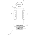
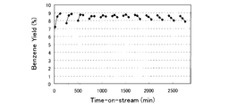
- the schematic diagram of the aromatic hydrocarbon manufacturing apparatus which concerns on 1st Embodiment of this invention The figure which shows the time change of the benzene yield when a catalytic reaction and a regeneration reaction are repeated in the aromatic hydrocarbon manufacturing apparatus which concerns on 1st Embodiment of this invention.
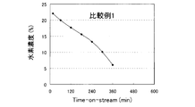
- the schematic diagram of the aromatic hydrocarbon manufacturing apparatus which is a comparative example of this invention The figure which shows the time change of the benzene yield at the time of performing a catalytic reaction continuously with the aromatic hydrocarbon manufacturing apparatus which is a comparative example of this invention.
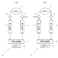
- FIG. 1 Schematic diagram of an aromatic hydrocarbon production apparatus according to the second embodiment of the present invention (when the first reactor performs a catalytic reaction),
- (b) Aromatic according to the second embodiment of the present invention The schematic diagram of a hydrocarbon production apparatus (when the 1st reactor is performing catalyst regeneration reaction).
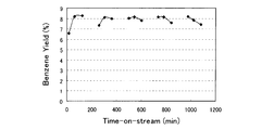
- the figure which shows the time change of the benzene yield in a 1st reactor when a catalytic reaction and a regeneration reaction are repeated with the aromatic hydrocarbon manufacturing apparatus which concerns on 2nd Embodiment of this invention.
- the present invention relates to a method for producing an aromatic hydrocarbon by reacting a lower hydrocarbon in the presence of a catalyst, and an amount of carbon dioxide gas that does not become excessive during the reaction is added to the regeneration gas at regular intervals. It is characterized by regenerating the catalyst by switching.
- off-gas a gas obtained by separating aromatic hydrocarbons generated from the gas after the catalytic reaction
- the catalyst reaction layer is provided in a plurality of stages (for example, m stages: m is an integer), and the catalyst is formed in the nth stage (n is an integer, n ⁇ m). It is possible to carry out the reaction and perform the regeneration reaction using the gas discharged at the nth stage as the regeneration gas at the (n + 1) th stage.
- the zeolitic catalyst used in the present invention is not particularly limited as long as it has a catalytic activity.
- ZSM-5 commercially available from Mordenite, Elionite, Ferrierite, and Mobil Corporation.
- Zeolite catalyst such as “4”, “ZSM-8”, “ZSM-11”, “ZSM-12”, “ZSM-20”, “ZSM-40”, “ZSM-35”, “ZSM-48” Can be used.
- crystalline aluminosilicates such as so-called mesoporous zeolites such as “MCM-41”, “MCM-48”, “MCM-50”, “FSM-16”, “M41S”, or polysilicates, gallosilicates, ferroaluminos
- zeolite-based catalysts such as foreign element-containing zeolites such as silicate and titanosilicate can be used.
- zeolite-based catalysts those suitable for hydration of olefins are crystalline aluminosilicates and gallosilicates having a pentasil structure.
- zeolite catalyst As the zeolite catalyst, a proton exchange type (H type) is usually used. In addition, some protons are from alkali metals such as Na, K and Li, alkaline earth elements such as Mg, Ca and Sr, and transition metal elements such as Fe, Co, Ni, Ru, Pd, Pt, Zr and Ti. It may be exchanged with at least one selected cation.
- the zeolite catalyst may contain an appropriate amount of Ti, Zr, Hf, Cr, Mo, W, Th, Cu, Ag, and the like.
- zeolite catalyst there are no particular restrictions on the form of the zeolite catalyst, and any form such as powder or granules may be used. Further, alumina, titania, silica, clayey compound, or the like may be used as the carrier or binder.
- the zeolite-based catalyst may be used by adding a binder such as silica, alumina, clay, etc., and molding it into pellets or extrudates.
- a binder such as silica, alumina, clay, etc.
- the lower hydrocarbon includes at least 50%, preferably 70% or more by weight of methane, and other saturated and unsaturated hydrocarbons having 2 to 6 carbon atoms. Means. Examples of these saturated and unsaturated hydrocarbons having 2 to 6 carbon atoms include ethane, ethylene, propane, propylene, n-butane, isobutane, n-butene and isobutene.
- the lower hydrocarbon aromatization reaction in the method for producing aromatic hydrocarbons and hydrogen from the lower hydrocarbons of the present invention can be carried out in a batch or flow reaction mode.
- the reaction is preferably carried out in a flow-type reaction mode such as a fixed bed, a moving bed, or a fluidized bed.
- the reaction temperature may be 300 ° C. to 900 ° C., preferably 450 ° C. to 800 ° C.
- the reaction pressure is 0.01 MPa to 1 MPa, preferably 0.1 MPa to 0.7 MPa.
- an aromatic hydrocarbon production apparatus 10 includes a first reactor 1, an aromatic separation apparatus 3, a hydrogen monitor 4, an offgas tank 6, a raw material gas tank 5, and a valve. 7 comprises.
- the first reactor 1 is filled with a catalyst for aromatizing lower hydrocarbons.
- a raw material gas for example, methane
- an aromatic hydrocarbon for example, benzene
- hydrogen is produced by the raw material gas contacting and reacting with the catalyst.
- the aromatic separation device 3 is supplied with the gas after the catalytic reaction discharged from the first reactor 1, and separates the aromatic compound produced in the first reactor 1 from the supplied gas.
- Aromatic separation means of the aromatic separation device 3 includes cooling separation means for recovering aromatics as a liquid or solid by cooling the gas, means for recovering organic components by aeration of the gas through the absorption liquid, and separation A means of using a membrane is conceivable and applicable.
- the hydrogen monitor 4 detects the hydrogen concentration in the off-gas with the aromatic separation device 3.
- the off gas of the first reactor 1 is supplied from the off gas tank 6 and the regeneration reaction of the catalyst in the first reactor 1 is also performed.
- the valve 7 When the valve 7 is switched so that the source gas (for example, methane-containing gas) is supplied from the source gas tank 5 to the first reactor 1, the methane reacts with the catalyst in the first reactor 1, and aromatic hydrocarbon (for example, , Benzene) and hydrogen.
- the source gas for example, methane-containing gas
- aromatic hydrocarbon for example, , Benzene
- the produced benzene and hydrogen (including unreacted methane and argon in the reaction gas) are sent to the aromatic separation device 3, and the aromatic hydrocarbons are separated and removed by the aromatic separation device 3. And the gas (off gas) which removed the aromatic hydrocarbon from the exhaust gas after reaction is stored in the off gas tank 6.
- the aromatic separation device 3 is provided with a hydrogen monitor 4 to measure the hydrogen concentration of the off-gas.
- the hydrogen concentration is a guideline for switching between the catalytic reaction and the regeneration reaction in the first reactor 1.
- valve 7 is switched so that the raw material gas is supplied to the first reactor 1 again to perform the catalytic reaction.
- HZSM-5 after silane treatment was added to an aqueous solution in which a predetermined amount (a molar concentration ratio of molybdenum and zinc of 10: 3) of ammonium molybdate and zinc nitrate was dissolved in 2000 ml of ion-exchanged water. The mixture was stirred for an hour and impregnated with zinc and molybdenum on HZSM-5.
- the obtained zinc / molybdenum-supported ZSM-5 (Zn (1.23 wt%) / Mo (6 wt%) / HZSM-5) was dried and then calcined at 550 ° C. for 8 hours to obtain a catalyst powder. Further, 15 inorganic binders were added to the catalyst powder 85, extruded into pellets, and fired to obtain a catalyst.
- the obtained catalyst was charged into the first reactor 1 of the reactor 10 of FIG. 1 and a test for producing aromatic hydrocarbons from lower hydrocarbons was conducted.
- the catalyst was evaluated based on the yield of benzene relative to the lower hydrocarbons circulated.
- the reaction conditions common to each test are shown below.
- Reaction temperature 780 ° C Pressure: 0.15 MPa Weight hourly space velocity (WHSV): 3000 ml / g-MFI / h
- WHSV Weight hourly space velocity
- methane 89%
- argon 9.9%
- carbon dioxide 1.5%
- the temperature of the catalyst was raised to 550 ° C. under an air stream and maintained for 2 hours, then the temperature was changed to a pretreatment gas of 20% methane: 80% hydrogen, heated to 700 ° C. and maintained for 3 hours. . Thereafter, the reaction gas was switched to a predetermined temperature (780 ° C.) to evaluate the catalyst.
- the aromatic hydrocarbon production apparatus 10 and the catalyst regeneration were performed by repeating a cycle in which the reaction is performed in the aromatic hydrocarbon production apparatus 10 for 2 hours and then the catalyst is regenerated for 2 hours.
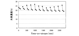
- the analysis results of benzene yield and hydrogen concentration are shown.
- the catalyst can be regenerated by off-gas and that the catalyst can be used for a long time.
- the hydrogen concentration of the off-gas in the first reactor 1 during the reaction is in the range of 15% to 25%. Therefore, instead of switching from the catalytic reaction to the regeneration reaction at regular intervals, it is possible to perform control to switch from the catalytic reaction to the regeneration reaction while monitoring the hydrogen concentration so that the hydrogen concentration does not fall below 15%.
- FIG. 5 shows the change over time in the benzene yield when the lower hydrocarbon is continuously contacted with the catalyst without performing the regeneration reaction.
- FIG. 6 shows the change over time in the hydrogen concentration in the offgas when the lower hydrocarbon is continuously brought into contact with the catalyst without performing the regeneration reaction.
- FIG. 7 shows an aromatic hydrocarbon production apparatus according to the second embodiment of the present invention.
- symbol is attached
- the aromatic hydrocarbon production apparatus 12 is characterized by including the first reactor 1 and the second reactor 2. By providing two reactors, the gas after reaction discharged in one reactor can be supplied as regeneration gas for the other reactor.
- the valve 8 is switched so that the raw material gas is supplied from the raw material gas tank 5 to the first reactor 1, and the valve 9 is switched so that the regenerated gas discharged from the second reactor 2 is discharged out of the system. .
- the first reactor 1 is filled with a lower hydrocarbon aromatization catalyst, and an aromatic compound such as benzene is produced from the supplied reaction gas (lower hydrocarbon).
- the exhaust gas from the first reactor 1 is sent to the aromatic separator 3, and the aromatic compound produced in the first reactor 1 is separated and removed by the aromatic separator 3.
- the gas (off gas) discharged from the aromatic separation device 3 is supplied to the second reactor 2.
- the lower hydrocarbon aromatization catalyst charged in the second reactor 2 is regenerated by the hydrogen contained in the offgas.
- the regeneration reaction of the catalyst in the first reactor 1 is performed.
- the regeneration reaction of the catalyst in the first reactor 1 will be described with reference to FIG.
- valve 9 is switched so that the source gas is supplied from the source gas tank 5 to the second reactor 2, and the gas after the regeneration reaction discharged from the first reactor 1 is out of the system.
- the valve 8 is switched so as to be discharged.
- the second reactor 2 is filled with a lower hydrocarbon aromatization catalyst, and an aromatic compound such as benzene is produced from the supplied lower hydrocarbon.
- the exhaust gas from the second reactor 2 is sent to the aromatic separation device 3, and the aromatic compound produced in the second reactor 2 is separated and removed by the aromatic separation device 3.
- the gas (off-gas) discharged from the aromatic separation device 3 is supplied to the first reactor 1.
- the lower hydrocarbon aromatization catalyst filled in the first reactor 1 is regenerated by hydrogen contained in the offgas.
- the aromatic hydrocarbon production apparatus 12 continuously produces aromatic hydrocarbons such as benzene efficiently. Can do. Furthermore, since two or more reactors may be provided and the reaction can be performed while regenerating the catalyst of the other reactor with the off-gas of the catalytic reaction without using a special regeneration gas, an economical manufacturing apparatus. Is realized.
- the lower hydrocarbon aromatization catalyst was charged into the first reactor 1 and the second reactor 2 shown in FIG. 7, and an aromatic hydrocarbon production reaction was performed.
- FIG. 8 to 10 show analysis results of benzene yield and hydrogen concentration when aromatic hydrocarbons are produced by the aromatic hydrocarbon production apparatus 12.
- FIG. 8 to 10 show analysis results of benzene yield and hydrogen concentration when aromatic hydrocarbons are produced by the aromatic hydrocarbon production apparatus 12.
- the hydrogen concentration in the off-gas of the first reactor 1 was 15% or more and 25% or less as in Example 1.
- off-gas is used as the regeneration gas, and it is clear that the regeneration capability decreases if the hydrogen concentration in the off-gas decreases.
- the hydrogen concentration is preferably 15% or more. That is, when the hydrogen concentration is less than 15%, the catalyst is excessively deteriorated, and the hydrogen concentration in the regeneration gas used for regeneration is also low, making it difficult to repeat the regeneration reaction.
- this invention is not limited to an Example, Reaction conditions, a catalyst (a kind and the amount of metal to carry
Landscapes
- Chemical & Material Sciences (AREA)
- Organic Chemistry (AREA)
- Engineering & Computer Science (AREA)
- Chemical Kinetics & Catalysis (AREA)
- Oil, Petroleum & Natural Gas (AREA)
- Materials Engineering (AREA)
- General Chemical & Material Sciences (AREA)
- Crystallography & Structural Chemistry (AREA)
- Organic Low-Molecular-Weight Compounds And Preparation Thereof (AREA)
- Low-Molecular Organic Synthesis Reactions Using Catalysts (AREA)
- Catalysts (AREA)
Abstract
Description
ベンゼン収率(%)={(生成したベンゼン量(mol))/(メタン改質反応に供されたメタン量(mol))}×100
各試験において共通の反応条件を以下に示す。
反応温度:780℃
圧力:0.15MPa
重量時間空間速度(WHSV):3000ml/g-MFI/h
反応ガスの組成:メタン(89%)、アルゴン(9.9%)、二酸化炭素(1.1%)
触媒の前処理は、触媒を空気気流下550℃まで昇温し、2時間維持した後、メタン20%:水素80%の前処理ガスに切り替えて、700℃まで昇温し、3時間維持した。その後、前記反応ガスに切り替えて所定の温度(780℃)まで昇温し触媒の評価を行った。
図7に、本発明の第2実施形態に係る芳香族炭化水素製造装置を示す。図1の芳香族炭化水素製造装置10と同一のものについては、同一の符号を付し詳細な説明は省略する。
2…第2反応器
3…芳香族分離装置
4…水素モニタ
10、11、12…芳香族炭化水素製造装置
Claims (5)
- 低級炭化水素を触媒と接触反応させて芳香族炭化水素を得る反応工程と、前記反応工程で使用された触媒を再生する再生工程を繰り返すことにより芳香族炭化水素を製造する方法において、
前記反応工程を経た排出ガスから、前記反応工程で生成した芳香族炭化水素を除去したガスであるオフガスを前記再生工程の再生ガスとして前記再生工程に供した
ことを特徴とする芳香族炭化水素製造方法。 - 前記オフガスの水素濃度に基づいて、反応工程から再生工程へと切り替える
ことを特徴とする請求項1に記載の芳香族炭化水素製造方法。 - 前記オフガスの水素濃度が15%以上の状態で、反応工程から再生工程へと切り替える
ことを特徴とする請求項1又は請求項2に記載の芳香族炭化水素製造方法。 - 低級炭化水素を触媒と接触反応させて芳香族炭化水素を得る反応工程と、前記反応工程で使用された触媒を再生する再生工程を繰り返す反応器と、
前記反応器から排出されるガスから、前記反応工程で生成した芳香族炭化水素を分離する芳香族炭化水素分離手段を備え、
前記反応工程を経た排出ガスから、前記反応工程で生成した芳香族炭化水素を除去したガスであるオフガスを前記再生工程の再生ガスとして供した
ことを特徴とする芳香族炭化水素製造装置。 - 前記反応器を複数備え、
少なくとも一つの反応器で前記反応工程を行い、
他の反応器に、該反応工程のオフガスを供給し、前記再生工程を行う
ことを特徴とする請求項4に記載の芳香族炭化水素製造装置。
Priority Applications (3)
| Application Number | Priority Date | Filing Date | Title |
|---|---|---|---|
| US13/146,272 US9358536B2 (en) | 2009-02-12 | 2010-01-15 | Method for producing aromatic hydrocarbon and apparatus for producing aromatic hydrocarbon |
| SG2011039740A SG171886A1 (en) | 2009-02-12 | 2010-01-15 | Method for producing aromatic hydrocarbon and apparatus for producing aromatic hydrocarbon |
| CN201080007489.5A CN102317240B (zh) | 2009-02-12 | 2010-01-15 | 芳香族烃的制备方法和芳香族烃的制备装置 |
Applications Claiming Priority (2)
| Application Number | Priority Date | Filing Date | Title |
|---|---|---|---|
| JP2009-029702 | 2009-02-12 | ||
| JP2009029702A JP5434115B2 (ja) | 2009-02-12 | 2009-02-12 | 芳香族炭化水素製造方法及び芳香族炭化水素製造装置 |
Publications (1)
| Publication Number | Publication Date |
|---|---|
| WO2010092849A1 true WO2010092849A1 (ja) | 2010-08-19 |
Family
ID=42561696
Family Applications (1)
| Application Number | Title | Priority Date | Filing Date |
|---|---|---|---|
| PCT/JP2010/050377 Ceased WO2010092849A1 (ja) | 2009-02-12 | 2010-01-15 | 芳香族炭化水素製造方法及び芳香族炭化水素製造装置 |
Country Status (5)
| Country | Link |
|---|---|
| US (1) | US9358536B2 (ja) |
| JP (1) | JP5434115B2 (ja) |
| CN (1) | CN102317240B (ja) |
| SG (1) | SG171886A1 (ja) |
| WO (1) | WO2010092849A1 (ja) |
Cited By (1)
| Publication number | Priority date | Publication date | Assignee | Title |
|---|---|---|---|---|
| WO2015151992A1 (ja) * | 2014-03-31 | 2015-10-08 | 三菱重工業株式会社 | 芳香族化合物の製造システム及びその製造方法 |
Families Citing this family (4)
| Publication number | Priority date | Publication date | Assignee | Title |
|---|---|---|---|---|
| CN104045505B (zh) * | 2013-03-15 | 2016-08-03 | 中石化洛阳工程有限公司 | 一种甲醇制低碳芳烃方法及装置 |
| US10099972B2 (en) * | 2013-12-06 | 2018-10-16 | Exxonmobil Upstream Research Company | Methods and systems for producing liquid hydrocarbons |
| CN105061127A (zh) * | 2015-06-03 | 2015-11-18 | 西北大学 | 一种低级烷烃芳构化反应-再生体系构建的工艺 |
| WO2020121287A1 (en) | 2018-12-14 | 2020-06-18 | Pixel Voltaic Lda | Catalytic methane decomposition and catalyst regeneration, methods and uses thereof |
Citations (2)
| Publication number | Priority date | Publication date | Assignee | Title |
|---|---|---|---|---|
| JP2003026613A (ja) * | 2001-07-12 | 2003-01-29 | National Institute Of Advanced Industrial & Technology | 低級炭化水素から芳香族炭化水素と水素を製造する方法 |
| JP2004269398A (ja) * | 2003-03-07 | 2004-09-30 | Masaru Ichikawa | 低級炭化水素の芳香族化触媒反応方法および芳香族化触媒反応装置ならびに芳香族化合物および水素の製造方法 |
Family Cites Families (7)
| Publication number | Priority date | Publication date | Assignee | Title |
|---|---|---|---|---|
| JPH0558919A (ja) * | 1990-12-20 | 1993-03-09 | Res Assoc Util Of Light Oil | 芳香族炭化水素の製法 |
| JP2001334152A (ja) | 2000-05-30 | 2001-12-04 | Masaru Ichikawa | 低級炭化水素の芳香族化合物化触媒ならびに低級炭化水素を原料とする芳香族化合物及び水素の製造方法 |
| TWI335239B (en) * | 2003-03-21 | 2011-01-01 | Stone & Webster Inc | Production of alkyl aromatic compounds with catalyst reactivation |
| JP2005343879A (ja) * | 2004-05-31 | 2005-12-15 | Masaru Ichikawa | 低級炭化水素の芳香族化触媒反応方法および芳香族化触媒反応装置ならびに芳香族化合物および水素の製造方法 |
| AU2008236524B2 (en) * | 2007-04-04 | 2010-11-25 | Exxonmobil Chemical Patents Inc. | Production of aromatics from methane |
| JP2008266244A (ja) * | 2007-04-24 | 2008-11-06 | Mitsubishi Chemicals Corp | 芳香族炭化水素の製造方法 |
| JP5062769B2 (ja) * | 2009-02-06 | 2012-10-31 | 株式会社日本製鋼所 | 低級炭化水素の直接改質方法 |
-
2009
- 2009-02-12 JP JP2009029702A patent/JP5434115B2/ja not_active Expired - Fee Related
-
2010
- 2010-01-15 US US13/146,272 patent/US9358536B2/en not_active Expired - Fee Related
- 2010-01-15 SG SG2011039740A patent/SG171886A1/en unknown
- 2010-01-15 WO PCT/JP2010/050377 patent/WO2010092849A1/ja not_active Ceased
- 2010-01-15 CN CN201080007489.5A patent/CN102317240B/zh not_active Expired - Fee Related
Patent Citations (2)
| Publication number | Priority date | Publication date | Assignee | Title |
|---|---|---|---|---|
| JP2003026613A (ja) * | 2001-07-12 | 2003-01-29 | National Institute Of Advanced Industrial & Technology | 低級炭化水素から芳香族炭化水素と水素を製造する方法 |
| JP2004269398A (ja) * | 2003-03-07 | 2004-09-30 | Masaru Ichikawa | 低級炭化水素の芳香族化触媒反応方法および芳香族化触媒反応装置ならびに芳香族化合物および水素の製造方法 |
Cited By (2)
| Publication number | Priority date | Publication date | Assignee | Title |
|---|---|---|---|---|
| WO2015151992A1 (ja) * | 2014-03-31 | 2015-10-08 | 三菱重工業株式会社 | 芳香族化合物の製造システム及びその製造方法 |
| AU2015239360B2 (en) * | 2014-03-31 | 2017-08-03 | Mitsubishi Heavy Industries, Ltd. | System for manufacturing aromatic compound and method for manufacturing same |
Also Published As
| Publication number | Publication date |
|---|---|
| JP2010184893A (ja) | 2010-08-26 |
| CN102317240B (zh) | 2014-07-30 |
| CN102317240A (zh) | 2012-01-11 |
| JP5434115B2 (ja) | 2014-03-05 |
| US9358536B2 (en) | 2016-06-07 |
| US20110288355A1 (en) | 2011-11-24 |
| SG171886A1 (en) | 2011-07-28 |
Similar Documents
| Publication | Publication Date | Title |
|---|---|---|
| US9144790B2 (en) | Process for the conversion of ethane to aromatic hydrocarbons | |
| AU2010313369B2 (en) | Process for the conversion of mixed lower alkanes to aromatic hydrocarbons | |
| US8969642B2 (en) | Method for providing a co-feed in the coupling of toluene with a carbon source | |
| CN101945840B (zh) | 用于乙烷转化成芳烃的方法 | |
| US20100185034A1 (en) | Process for producing aromatic hydrocarbon | |
| US20140155258A1 (en) | Process for the conversion of ethane to aromatic hydrocarbons | |
| JP2009516015A (ja) | 炭化水素混合物から芳香族炭化水素および液化石油ガスを製造する方法 | |
| JP5481996B2 (ja) | 芳香族炭化水素製造方法 | |
| JP5434115B2 (ja) | 芳香族炭化水素製造方法及び芳香族炭化水素製造装置 | |
| CN103313959B (zh) | 混合低级烷烃转化成芳烃的方法 | |
| JP5824462B2 (ja) | エチルベンゼンの調製方法 | |
| WO2012002269A1 (ja) | 芳香族炭化水素製造方法 | |
| JP5423028B2 (ja) | 芳香族炭化水素製造方法 | |
| JP5014138B2 (ja) | エチレン及びプロピレンを製造する方法 | |
| JP5283665B2 (ja) | 低級炭化水素の芳香族化合物化触媒ならびに低級炭化水素を原料とする芳香族化合物及び水素の製造方法 | |
| JP4943671B2 (ja) | 低級炭化水素の芳香族化触媒及びそれを用いて低級炭化水素から芳香族炭化水素と水素とを製造する方法 | |
| WO2011118279A1 (ja) | 芳香族化合物製造方法 | |
| JP2015063560A (ja) | 芳香族化合物製造方法 |
Legal Events
| Date | Code | Title | Description |
|---|---|---|---|
| WWE | Wipo information: entry into national phase |
Ref document number: 201080007489.5 Country of ref document: CN |
|
| 121 | Ep: the epo has been informed by wipo that ep was designated in this application |
Ref document number: 10741129 Country of ref document: EP Kind code of ref document: A1 |
|
| WWE | Wipo information: entry into national phase |
Ref document number: 13146272 Country of ref document: US |
|
| NENP | Non-entry into the national phase |
Ref country code: DE |
|
| 122 | Ep: pct application non-entry in european phase |
Ref document number: 10741129 Country of ref document: EP Kind code of ref document: A1 |