WO2010092746A1 - 地中連続壁用鋼材の製造方法 - Google Patents
地中連続壁用鋼材の製造方法 Download PDFInfo
- Publication number
- WO2010092746A1 WO2010092746A1 PCT/JP2010/000273 JP2010000273W WO2010092746A1 WO 2010092746 A1 WO2010092746 A1 WO 2010092746A1 JP 2010000273 W JP2010000273 W JP 2010000273W WO 2010092746 A1 WO2010092746 A1 WO 2010092746A1
- Authority
- WO
- WIPO (PCT)
- Prior art keywords
- sheet pile
- steel sheet
- steel
- bending
- underground continuous
- Prior art date
- Legal status (The legal status is an assumption and is not a legal conclusion. Google has not performed a legal analysis and makes no representation as to the accuracy of the status listed.)
- Ceased
Links
Images













Classifications
-
- E—FIXED CONSTRUCTIONS
- E02—HYDRAULIC ENGINEERING; FOUNDATIONS; SOIL SHIFTING
- E02D—FOUNDATIONS; EXCAVATIONS; EMBANKMENTS; UNDERGROUND OR UNDERWATER STRUCTURES
- E02D5/00—Bulkheads, piles, or other structural elements specially adapted to foundation engineering
- E02D5/02—Sheet piles or sheet pile bulkheads
- E02D5/03—Prefabricated parts, e.g. composite sheet piles
- E02D5/04—Prefabricated parts, e.g. composite sheet piles made of steel
Definitions
- the present invention relates to a method for producing a steel material for an underground continuous wall for constructing an underground continuous wall used as a retaining wall, a foundation structure, a retaining wall, a seawall of a harbor river, a water blocking wall, etc.
- This application claims priority based on Japanese Patent Application No. 2009-030310 filed in Japan on February 12, 2009, the contents of which are incorporated herein by reference.
- steel sheet piles are generally used as steel materials for underground continuous walls when building earth retaining walls to prevent the collapse of earth and sand, and retaining walls that support embankments and cuts.
- H-section steel 120 is fixed to a steel sheet pile 110 having a substantially hat-shaped cross section.
- a wall steel 101 has been proposed (see, for example, Patent Documents 1 and 2).
- the steel material 101 for the underground continuous wall is configured by fixing one flange portion 122 of the H-section steel 120 to the web portion 111 of the steel sheet pile 110.
- the corner portion formed by the web portion 111 of the steel sheet pile 110 and the flange portion 122 of the H-shaped steel 120 is continuous or discrete along the longitudinal direction.
- a method of fixing by welding is used.
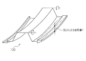
- steel sheet piles and H-section steel are formed at the factory by rolling and pressing. Therefore, like the hat-type steel sheet pile 130 shown in FIGS. 14A and 14B, the steel sheet pile and the H-shaped steel are shipped from the factory in a state where deformation called bending or warping has occurred.
- a bend here means that a steel sheet pile or H-shaped steel curves in the horizontal direction along the wall surface of the constructed underground continuous wall (refer FIG. 14A).
- warpage means that a steel sheet pile or the like is bent in a direction perpendicular to the wall surface of the constructed underground continuous wall (see FIG. 14B).
- Steel sheet piles are required to be placed while being fitted with adjacent steel sheet pile joints when constructing the underground continuous wall body, so that the joint resistance during placement is required to be kept below a certain value. Therefore, in order to prevent the joint portions of the adjacent steel sheet piles that have been placed from separating from each other, it is required that the deformation amount of the bending or warping of the steel material be a certain control value or less when shipped at the factory.
- the deformation amount X (m) due to bending is required to satisfy the following formula (1). Therefore, it is required that the deformation Y (m) due to warpage satisfies the following formula (2).
- the amount of deformation due to bending and warping required for JIS G3192 is specified for H-section steel.
- the steel material 101 for the underground continuous wall is also driven while fitting the joint portions 117 of the steel sheet piles 110 constituting the adjacent steel material 101 for the underground continuous wall when the underground continuous wall body is constructed.
- the underground continuous wall steel 101 similarly to the hat-type steel sheet pile 130 described above, the underground continuous wall steel 101 also has a certain control value for the amount of deformation due to bending or warping of the steel sheet pile 110 constituting the underground continuous wall steel 101 after assembly processing. It is necessary to do the following.
- the deformation amount of the steel sheet pile 110 of the underground continuous wall steel 101 after the assembly is mainly formed by rolling or the like performed before welding.
- the amount of deformation of the steel sheet pile 110 that has been generated in advance and the amount of deformation of the steel sheet pile 110 caused by thermal strain due to welding are combined.
- the underground continuous wall is caused by thermal strain during welding.
- the amount of bending and warping of the steel material 1 increases, and the possibility of deviating from the target management value increases.
- correction work by linear heating is generally performed after welding.
- This linear heating for example, a part of the steel sheet pile 110 such as the joint portion 117 is partially contracted by heating and quenching, and bending and warping occurring in the steel material 101 for the underground continuous wall.
- This is a method of correcting bending and warping by applying temperature stress in the opposite direction.
- the work requires several hours to about a day, and the work cost is high.
- correction cannot be performed by linear heating, and if the control value is deviated after assembling the steel material 110 for the underground continuous wall body, there is a problem that it cannot be shipped from the factory.
- Patent Document 2 as an improvement measure, a method of carrying out the welding of the left and right ends of the steel sheet pile web portion and the flange portion of the H-shaped steel at the same time, or after completion of one of the left and right welding operations, A method of starting the welding operation on the other side under a condition where the temperature of the welded portion is 200 ° C. or higher is disclosed. Thereby, in the disclosed technique of Patent Document 2, thermal strain due to welding at both the left and right ends is equalized.
- the present invention has been devised in view of the above-described problems, and its purpose is to provide a steel material for underground continuous wall in which a steel sheet pile having a substantially hat-shaped cross section and an H-shaped steel are combined.
- a first aspect of the present invention is a facing step in which the web portion of the steel sheet pile faces the flange portion of the H-shaped steel; A first fixing step of fixing the steel sheet pile and the H-shaped steel at a first fixing position; by bending the steel sheet pile and the H-shaped steel, bending in the width direction of the steel sheet pile and the H-shaped A bending correction step of correcting the bending in the width direction of the steel; and a second fixing position in which the steel sheet pile and the H-shaped steel are fixed at a second fixing position spaced apart from the first fixing position in the longitudinal direction of the steel sheet pile. And a welding step of welding the steel sheet pile and the H-shaped steel along a longitudinal direction of the steel sheet pile.
- the bending correction step is performed on the steel sheet pile at a position spaced from the first fixed position in the longitudinal direction of the steel sheet pile.
- a bending correction wedge piece driving step is performed on the steel sheet pile at a position spaced from the first fixed position in the longitudinal direction of the steel sheet pile.
- the first bending correction jig may be attached to the steel sheet pile by welding.
- the thickness of the steel sheet pile is changed by deforming the steel sheet pile and the H-shaped steel. You may further provide the curvature correction process which corrects the curvature of a vertical direction and the curvature of the thickness direction of the said H-section steel.
- the warp correction step is performed on the steel sheet pile at a position spaced from the first fixed position in the longitudinal direction of the steel sheet pile.
- a first warp correction wedge piece driving step for driving is performed on the steel sheet pile at a position spaced from the first fixed position in the longitudinal direction of the steel sheet pile.
- the first warp correction jig may be attached to the steel sheet pile by welding.
- the steel sheet pile is composed of two Z-shaped steel sheet piles connected so as to have a hat-shaped steel sheet pile or a substantially hat-shaped cross section. May be.
- the first fixing step includes a step of fixing a fixing warp correction jig to the steel sheet pile; and the fixing warp correction treatment. And a step of driving a fixing wedge piece between the tool and the flange portion of the H-shaped steel.
- the steel sheet pile which comprises the steel material for underground continuous walls so that the bending and curvature may become small, it is H form.
- the steel is also deformed in the direction opposite to the direction in which the steel sheet pile is deformed, and then fixed in the deformed state.
- the elastic restoring force which acts on H-section steel and a steel sheet pile counters. That is, the steel sheet pile is bent and warped by the elastic restoring force of the H-shaped steel, and is held. For this reason, it becomes possible to perform straightening work itself easily in the assembly process of the steel material for underground continuous walls.
- the steel sheet pile is not corrected after forming such as rolling.
- the fixing work is performed after correcting the bending and warping of the steel sheet pile
- it is possible to mass-produce steel materials for underground continuous walls having bending and warping lower than the control values required for bending and warping, and the occurrence of straightening work such as linear heating correction that has been conventionally performed after welding processing Can be significantly suppressed.
- the steel sheet pile correction operation is performed simply by driving a wedge piece such as a bending correction wedge piece or a warp correction wedge piece. Since it can be realized with only human power without the need for special heavy machinery or tools, it is extremely workable and economical.
- the curvature deformation rate before and behind the assembly of the steel material for underground continuous walls assembled by application of the present invention is shown. It is a front view of the steel material for underground continuous walls for demonstrating a prior art. It is a perspective view for demonstrating the bending of a steel sheet pile. It is a perspective view for demonstrating the curvature of a steel sheet pile.
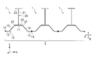
- FIG. 1A shows a front view of steel material 1 for underground continuous wall obtained by the production method of the present invention.
- a is the longitudinal direction of the steel sheet pile
- b is the width direction of the steel sheet pile
- c is the thickness direction of the steel sheet pile.
- the underground continuous wall steel 1 includes a steel sheet pile 10 and an H-shaped steel 20.
- the steel sheet pile 10 is integrally provided in parallel with the web portion 11 from the web portion 11, the flange portion 12 integrally provided so as to be inclined inward on both sides of the web portion 11, and the tip of the flange portion 12.
- the arm part 13 and the joint part 14 provided at the tip of the arm part 13 are provided.
- the steel sheet pile 10 is formed into a substantially hat-shaped cross section by the web part 11, the flange part 12, and the arm part 13, and is constituted by a so-called hat-type steel sheet pile in this embodiment.
- one joint part 14a and the other joint part 14b are adjusted so as to be point-symmetric with each other in this embodiment.
- the H-section steel 20 includes a web portion 21 and a pair of flange portions 22 and 23 provided at both ends of the web portion 21.
- One flange portion 22 in the H-shaped steel 20 is fixed to the outside of the web portion 11 in the steel sheet pile 10 by fillet welding 27.
- This fillet weld 27 is applied to a corner portion formed by the web portion 11 of the steel sheet pile 10 and the flange portion 22 of the H-section steel 20.
- the fillet welds 27 may be applied discretely at arbitrary intervals along the longitudinal direction of the underground continuous wall steel 1 or may be applied continuously.
- the steel sheet pile 10 and the H-section steel 20 are formed by, for example, hot rolling or cold pressing.
- FIG. 1B shows a plan view as an example of the underground continuous wall 5 constructed by connecting the steel materials 1 for the underground continuous wall having such a configuration to each other.
- the underground continuous wall body 5 is configured as one wall body connected to each other via a joint portion 14 in the steel material 1 for the continuous wall in each region.
- the underground continuous wall 5 is configured by continuously arranging the same underground continuous wall steel 1.
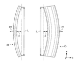
- FIG. 2A is a side view schematically showing the configuration of the steel sheet pile 10 and the H-shaped steel 20 used when assembling the steel material 1 for the underground continuous wall
- FIG. 2B is an upper surface schematically showing these configurations.
- the H-section steel 20 has a bending in a direction opposite to the bending of the steel sheet pile 10 or a bending in the same direction that is smaller than this.
- the steel sheet pile 10 and the H-section steel 20 each have a bending in the opposite direction.
- the bending of the steel sheet pile 10 and the H-section steel 20 here means that the steel sheet pile 10 and the H-section steel 20 are in the horizontal direction A along the wall surface of the built underground continuous wall body 5 as shown in FIG. 1A. It means that it is curved in a substantially convex shape.
- the horizontal direction A here means the width direction of the web part 11 of the steel sheet pile 10, and the width direction of the flange part 22 of the H-section steel 20, and in other words, the steel sheet pile 10 or the H-shape. It means a direction perpendicular to the longitudinal direction of the steel 20 and parallel to the web portion 11 of the steel sheet pile 10 and the flange portion 22 of the H-section steel 20.
- the H-section steel 20 has a warp in the opposite direction to the warp of the steel sheet pile 10 or a warp smaller than this in the same direction.
- the steel sheet pile 10 and the H-section steel 20 each have a warp in the opposite direction.
- the warp of the steel sheet pile 10 and the H-section steel 20 here is substantially the same as the direction of the steel sheet pile 10 or the H-section steel 20 in the direction B perpendicular to the wall surface of the built underground continuous wall body 5 as shown in FIG. 1B. It means that it is curved in a convex shape.
- the direction B here means the thickness direction of the web portion 11 of the steel sheet pile 10 and the thickness direction of the flange portion 22 of the H-section steel 20.
- the steel sheet pile 10 has a bend in the direction P1, as shown in FIG. 2B, and the H-section steel 20 is in the direction P2 opposite to the direction P1.
- the steel sheet pile 10 has a warp in the direction Q1
- the H-section steel 20 has a warp in the direction Q2 which is the direction opposite to the direction Q1.
- 2A and FIG. 2B is a symbol as an index indicating the amount of deformation, and does not mean a specific size, but about bending or warping of the steel sheet pile 10 and the H-section steel 20. The amount of deformation need not be the same size.
- FIG. 3 is a front view showing a state during the assembly of the steel material 1 for the underground continuous wall.
- a bending correction jig 31 and a warp correction jig 33 fixed to one surface side of the steel sheet pile 10 are used.
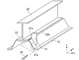
- 4A is a perspective view for explaining a state in which the bending correction jig 31 is fixed
- FIG. 5A is a perspective view for explaining a state in which the warp correction jig 33 is fixed.
- the joint portion 14 is omitted to simplify the drawing.
- the bending straightening jig 31 is opposed to the attachment surface 31a that is abutted and fixed along one surface side of the steel sheet pile 10 and the side surface 22a of the flange portion 22 of the H-section steel 20 with a space therebetween. And a pressing surface 31b.
- the bending correction jig 31 is made of a substantially trapezoidal steel plate.
- the mounting surface 31a of the bending correction jig 31 has a shape corresponding to a portion to be contacted on one surface side of the steel sheet pile 10. As long as the bending correction jig 31 includes the attachment surface 31a and the pressed surface 31b, the shape thereof is not particularly limited.
- the warp correction jig 33 is opposed to the mounting surface 33a that is abutted and fixed along one side of the steel sheet pile 10 and the inner surface 22b of the flange portion 22 of the H-shaped steel 20 with a space therebetween. And a pressing surface 33b.
- the warp correction jig 33 is composed of a substantially L-shaped steel plate.
- the attachment surface 33a of the warp correction jig 33 has a shape corresponding to a portion to be contacted on one surface side of the steel sheet pile 10.
- the shape of the warp correction jig 33 is not particularly limited as long as it includes the mounting surface 33a and the pressed surface 33b.
- the bend correction jig 31 and the warp correction jig 33 are not particularly limited with respect to the fixing means for the steel sheet pile 10, but are repeatedly attached and detached as described later, so that welding is performed from the viewpoint of improving workability. It is preferable to fix. In this case, after being fixed to the steel sheet pile 10, it can be removed by striking with a tool such as a hammer, and the removal work can be easily performed. Further, the bending correction jig 31 and the warp correction jig 33 both have their mounting surfaces 31a and 33a fixed to one surface side of the flange portion 12 of the steel sheet pile 10, but the steel sheet pile to which the H-shaped steel 20 is fixed. As long as it is a position on one side of 10 and the following correction operation can be performed, the position to be fixed is not particularly limited.
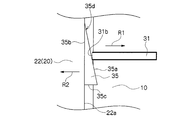
- FIG. 4A a bending correction wedge piece 35 is driven between the pressed surface 31b of the bending correction jig 31 and the side surface 22a of the flange portion 22 of the H-section steel 20 facing the pressing surface 31b.
- FIG. 4B is a top view showing a state after the bending correction wedge piece 35 is driven.
- This bend correcting wedge piece 35 has inclined surfaces 35a and 35b which are inclined with respect to each other, and is formed at an acute angle by these inclined surfaces 35a and 35b.
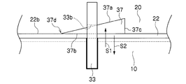
- FIG. 5A is a side view showing a state after the warp correcting wedge piece 37 has been driven.
- the warp correcting wedge piece 37 has inclined surfaces 37a and 37b that are inclined with respect to each other, and is formed at an acute angle by the inclined surfaces 37a and 37b.
- Both the bend correcting wedge piece 35 and the warp correcting wedge piece 37 are formed of a substantially triangular steel plate in this embodiment, but the wedge having such inclined surfaces 35a, 35b, 37a, 37b. If it is comprised as, the shape and material will not be specifically limited.
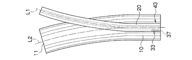
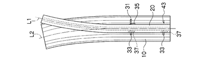
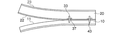
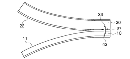
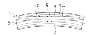
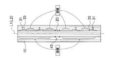
- FIGS. 6A to 6D are schematic top views for explaining a process at the time of assembling the steel material 1 for underground continuous wall, and FIGS. 7A to 7D are schematic side views thereof.
- the relative position in the width direction and the longitudinal direction of the steel sheet pile 10 and the H-section steel 20 in a part of the range extending in the longitudinal direction Position the orientation.
- the center position L2 in the width direction of the web portion 11 of the steel sheet pile 10 and the center position L1 in the width direction of the flange portion 22 of the H-section steel 20 are substantially matched in a part of the range extending in the longitudinal direction.
- the web portion 11 of the steel sheet pile 10 and the flange portion 22 of the H-shaped steel 20 are brought into contact with each other.
- the end portions in the longitudinal direction of the steel sheet pile 10 and the H-shaped steel 20 are made to face each other at the time of positioning.
- the steel sheet pile 10 and the H-section steel 20 are fixed at the positioned part.
- fixing metal fittings such as welding, bolting, screw-type clamps, and lever blocks (registered trademark) may be used, or other appropriate jigs for fixing may be used. Also good.
- the steel sheet pile 10 and the H-section steel 20 are fixed using the warp correction jig 33.
- the warp correction jig 33 and the H-shaped steel are fixed to the one side of the steel sheet pile 10 by welding or the like at the position where the steel sheet pile 10 is fixed.
- a warp correcting wedge piece 37 is driven between the inner surface 22 b of the 20 flange portions 22.
- the warp correction wedge piece 37 is arranged with the tip 37 d of the warp correction wedge piece 37 disposed between the warp correction jig 33 and the flange portion 22 of the H-shaped steel 20.
- the warp correcting wedge piece 37 is driven by striking the bottom surface 37c with a tool such as a hammer.
- a load in the direction S2 is applied to the H-section steel 20. That is, the steel sheet pile 10 and the H-shaped steel 20 are fixed to each other at the position where the steel sheet pile 10 and the H-shaped steel 20 are positioned by driving the wedge piece 37 for correcting warpage.
- the bending and warping of the steel sheet pile 10 are corrected.
- the steel sheet pile 10 is deformed so that the bending is corrected, and the steel sheet pile 10 is deformed in a direction opposite to the direction in which the steel sheet pile 10 is deformed with respect to the bending.
- the width direction center position L2 of the web portion 11 and the width direction center position L1 of the flange 22 of the H-shaped steel 20 are substantially matched.
- the correction of the warp is performed by deforming the steel sheet pile 10 so that the warp is corrected, and by deforming the H-shaped steel 20 in a direction opposite to the direction in which the steel sheet pile 10 is deformed with respect to the warp. This is performed by substantially pressing the web portion 11 and the flange portion 22 of the H-shaped steel 20 together.
- the steel sheet pile 10 and the H-section steel 20 fixed after positioning are separated from each other in the longitudinal direction from the fixing portion (fixed position) 43.
- a bending correction jig 31 is fixed to one side of the sheet pile 10 by welding or the like.
- a bending correction wedge piece 35 is driven between the pressed surface 31b of the bending correction jig 31 and the side surface 22a of the H-section steel 20.
- the bending correction wedge piece 35 is arranged with the tip 35 d of the bending correction wedge piece 35 disposed between the bending correction jig 31 and the flange portion 22 of the H-shaped steel 20. It is driven by hitting the bottom surface 35c of the bending correction wedge piece 35 with a tool such as a hammer.
- the inclined surface 35 a of the bending correction wedge piece 35 in contact with the pressed surface 31 b of the bending correction jig 31 presses the bending correction jig 31 by driving the bending correction wedge piece 35. Then, the load in the direction R1 is applied to the steel sheet pile 10 to which the bend correction jig 31 is fixed, and the bend correction wedge piece 35 in contact with the side surface 22a of the flange portion 22 of the H-section steel 20 is inclined. The surface 35b presses the flange portion 22 to apply a load in the direction R2 to the H-section steel 20.
- the bending correction jig 31 is opposite to the center position L2 in the width direction of the web portion 11 of the steel sheet pile 10 with respect to the center position L1 of the flange portion 22 of the H-section steel 20 in the top view. It is necessary to fix to the steel sheet pile 10 by the side. As a result, when the bending correction wedge piece 35 is driven, a load is applied to the steel sheet pile 10 and the H-shaped steel 20 in opposite directions, and according to the driving amount of the bending correction wedge piece 35, the steel sheet pile 10 is The deformation is performed so that the bending is corrected, and the H-section steel 20 is deformed in a direction opposite to the direction in which the bending of the steel sheet pile 10 is deformed.
- the bending correction wedge piece 35 has a center position L2 in the width direction of the web portion 11 of the steel sheet pile 10 and a width of the flange portion 22 of the H-section steel 20 in the portion where the bending correction wedge piece 35 is driven. It is driven in until it is deformed to the extent that it substantially matches the center position L1 of the direction.
- a warp correction jig is formed on one surface side of the steel sheet pile 10 at a position spaced in the longitudinal direction from a fixing portion (fixed position) 43 formed after positioning. 33 is fixed by welding or the like.
- a load is applied to the steel sheet pile 10 and the H-shaped steel 20 in opposite directions, respectively, and according to the drive amount of the warp correction wedge piece 37.
- the steel sheet pile 10 is deformed so that the warp is corrected, and the H-section steel 20 is deformed in a direction opposite to the direction in which the warp of the steel sheet pile 10 is deformed.
- the warp correcting wedge piece 37 is driven until the steel sheet pile 10 and the H-shaped steel 20 are deformed so as to be substantially press-bonded to each other at the portion where the warp correcting wedge piece 37 is driven.
- the steel sheet pile 10 and the H-shaped steel 20 are deformed at a portion where the bend correction jig 31 and the warp correction jig 33 are fixed by driving the bend correction wedge piece 35 and the warp correction wedge piece 37. It is held in a deformed state.
- the bend-correcting wedge piece 35 and the warp-correcting wedge piece 37 are driven by a fixed portion (fixed position) 43 formed after positioning. Multiple times so as to be spaced apart from each other in the longitudinal direction. Thereby, as shown to FIG. 6D and FIG. 7D, the bending and curvature of the steel sheet pile 10 are corrected over the full length of a longitudinal direction.
- the web portion 11 of the steel sheet pile 10 and the flange portion 22 of the H-section steel 20 are held while maintaining the deformed state of the steel sheet pile 10 and the H-section steel 20. Weld along the longitudinal direction. In this case, fillet weld 27 is performed on the corner formed by the web portion 11 of the steel sheet pile 10 and the flange portion 22 of the H-section steel 20. In this case, since the steel sheet pile 10 and the H-section steel 20 are brought into a pressure-bonded state along the longitudinal direction by the driving of the warp correcting wedge piece 37, the welding operation can be easily advanced.
- the steel sheet pile 10 constituting the steel material 1 for the underground continuous wall is bent and deformed so that the warpage is reduced, and the H-shaped steel 20 is also opposite to the direction in which the steel sheet pile 10 is deformed. After being deformed, they are fixed in the deformed state, so that the elastic restoring force acting on them cancels each other. That is, the steel sheet pile 10 is held in a state in which the bending and warping of the steel sheet pile 10 are corrected by the elastic restoring force of the H-shaped steel 20.
- the bending and curvature of the steel sheet pile 10 which comprises the steel material 1 for underground continuous walls after a welding process. It is possible to greatly reduce the amount of deformation. For this reason, it is possible to mass-produce the steel material 1 for underground continuous wall having a bending or warping lower than the control value required for bending or warping, and for straightening work such as linear heating correction that has been conventionally performed after welding processing. Occurrence can be greatly suppressed.
- the correction work of the steel sheet pile 10 can be realized only by performing a simple operation such as driving a wedge piece such as a bending correction wedge piece 35 or a warp correction wedge piece 37, and a special heavy machine. Because it can be realized by human power without the need for tools and tools, it is extremely workable and economical.
- 8A to 8D are schematic side views for explaining the steps of the second embodiment of the present invention.
- the H-section steel 20 is arranged on the web portion 11 of the steel sheet pile 10 in the same procedure as in the first embodiment, and after positioning these, in part. Fix it.
- the bend correcting wedge piece 35 and the warp correcting wedge piece 37 are driven in order to correct the bend and the warp.
- the warp correcting wedge piece 37 is driven after positioning.
- the steel sheet pile 10 and the H-section steel 20 are fixed by welding or the like at a fixing portion (fixed position) 43 which is a part.
- the steel sheet pile 10 and the H-section steel 20 are fixed by spot welding 41 on both sides in the longitudinal direction of the warp correction jig 33.
- a bending correction jig 31 (not shown) is attached to the steel sheet pile 10 at a position spaced from the fixing portion (fixed position) 43 formed after positioning. It is fixed by welding or the like, and a bending correction wedge piece 35 is driven in to correct the bending of the steel sheet pile 10. Subsequently, the warp correction jig 33 previously removed on the opposite side to which the H-shaped steel 20 is sandwiched with respect to the fixed bending correction jig 31 is fixed to the steel sheet pile 10 by welding or the like. The piece 37 is driven.
- the steel sheet pile 10 and the H-shaped steel 20 are fixed by spot welding 41 or the like at the portion where the bending correction wedge piece 35 or the warp correction wedge piece 37 is driven, and then the bending correction jig 31 is fixed. Then, the warp correction jig 33 is removed from the steel sheet pile 10. Thereafter, as shown in FIG. 8C, the above-described operations are repeated by using these correction jigs at the time of the bending correction operation and the warp correction operation at the positions separated in the next longitudinal direction. As shown, the steel sheet pile 10 and the H-section steel 20 are welded and fixed along the longitudinal direction.
- the same bend correction jig 31, the warp correction jig 33, the bend correction wedge piece 35, and the warp correction wedge piece 37 are repeatedly used during a plurality of bend correction operations and warp correction operations. It becomes possible. That is, it becomes possible to reduce the number of required bending correction jigs 31 and warpage correction jigs 33, and to reduce the cost required for the assembly work.
- 9A to 9D are schematic top views for explaining the steps of the third embodiment of the present invention.
- the H-section steel 20 which has the curvature of the opposite direction to the curvature of the steel sheet pile 10 and has the curvature of the same direction as the curvature of the steel sheet pile 10 is used, and the steel sheet pile 10 and the H-section steel 20 The same amount of deformation due to warpage is used.
- the flange portion 22 of the H-section steel 20 is disposed on the web portion 11 of the steel sheet pile 10 at the intermediate portion 47 in the range extending in the longitudinal direction between the steel sheet pile 10 and the H-section steel 20.
- the center position L2 in the width direction of the web portion 11 of the steel sheet pile 10 and the center position L1 in the width direction of the flange 22 of the H-section steel 20 are positioned so as to be substantially matched, and then fixed by spot welding 41. To do.
- the bending of the steel sheet pile 10 is corrected at a position spaced apart from the fixing portion (fixed position) 43 between the steel sheet pile 10 and the H-shaped steel 20 formed after the positioning.
- the bending correction wedge piece 35 is driven.
- the bending correction jig 31 is opposite to the center position L2 in the width direction of the web portion 11 of the steel sheet pile 10 with respect to the center position L1 of the flange portion 22 of the H-section steel 20 in the top view. It fixes to the steel sheet pile 10 by the right side in the figure which is a side.
- the bending correction wedge piece 35 is driven multiple times so as to be spaced apart from the fixing portion (fixed position) 43 formed after positioning on both sides in the longitudinal direction. Then, the steel sheet pile 10 and the H-section steel 20 are welded along the longitudinal direction.
- the cross-section in the weak axis direction in which the second-order moment in the strong axis direction, which is the plate thickness direction, of the flange portion 22 of the H-section steel 20 is the plate thickness direction in the web portion 21. Since the rigidity in the strong axis direction, which is the direction in which the H-section steel 20 is warped, is greater than the secondary moment, the steel sheet pile 10 is unlikely to be warped greatly due to thermal strain during welding. Therefore, even in this case, it is possible to mass-produce the steel material 1 for the underground continuous wall having bending and warping lower than the control values required for bending and warping, such as linear heating correction that has been conventionally performed after welding processing. The expected effect of the present invention that the occurrence of correction work is greatly suppressed is exhibited.
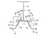
- the steel material 1 for underground continuous walls used as the object of application of this invention is not limited to the example mentioned above, but rather than the width direction length of the web part 11 of the steel sheet pile 10, as shown to FIG. 10A.
- the length in the width direction of the flange portion 22 of the H-shaped steel 20 may be long.
- the bending correction jig 31 is formed of an L-shaped steel plate so that the pressed surface 31 b faces the side surface 22 a of the flange portion 22 of the H-section steel 20.
- the warp correction jig 33 is composed of a substantially U-shaped steel plate so that the pressed surface 33 b faces the inner surface 22 b of the flange portion 22 of the H-section steel 20.
- the steel sheet pile 10 is deformed to be bent and warped by use of the bending correction jig 31, the bending correction wedge piece 35, and the like, and then the web portion 11 of the steel sheet pile 10 and the flange portion of the H-section steel 20 are used. 22 is fixed by applying flare welding 29 discretely or continuously in the longitudinal direction.
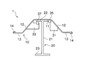
- the flange part 22 of the H-section steel 20 may be being fixed inside the web part 11 in the steel sheet pile 10, as shown to FIG. 10B.
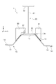
- the steel material 1 for underground continuous walls in this invention may be comprised by combining the steel sheet pile 10 with what is called a Z-shaped steel sheet pile 50, as shown to FIG. 11A.
- the Z-type steel sheet pile 50 includes a web portion 51, arm portions 52 provided on both sides of the web portion 51, and a joint portion 14 provided at the distal end of the arm portion 52. 52 and a substantially Z-shaped cross section.
- the steel sheet pile 10 in FIG. 11A has a Z-type steel sheet pile 50A in which the joint portions 14 on both sides are opened on the lower side in the drawing, and the joint portions 14 on both sides are opened in the upper side in the drawing, and the arrangement of the web portion 51 and the arm portion 52 is arranged.
- the cross-sectional shape is substantially hat-shaped.
- the joint portion 14 fitted to each other is welded or pressed by a press machine before assembling the steel material 1 for underground continuous wall. It is desirable to fix and integrate them by so-called caulking (mechanical adhesion) or the like and process them into a substantially hat-shaped cross section.
- the web part 11 as the steel sheet pile 10 is formed by the arm part 52 having the joint part 14 fitted to each other, and the flange as the steel sheet pile 10 is formed by the web part 51 of each Z-shaped steel sheet pile 50.
- the arm portion 13 as the steel sheet pile 10 is formed by the arm portion 52 of the Z-shaped steel sheet pile 50 that is formed with the portion 12 and is not fitted to the other joint portion 14.
- the steel sheet pile 10 may be composed of a hat-type steel sheet pile as shown in FIGS. 1A and 1B, and as shown in FIG. 11A, two Z-shapes connected so as to have a substantially hat-shaped cross section. You may be comprised from the steel sheet piles 50A and 50B. That is, the steel sheet pile 10 has a shape in which the joint portions 14 on both sides in the width direction can be fitted to other joint portions 14 in the other adjacent steel material 1 for underground continuous wall. As long as the fitting strength is increased so that the joint portions 14 are not separated from each other at the time, the shape is not particularly limited.
- FIG. 1A In addition to the case where the joint portions 14 on both sides in the width direction of the steel sheet pile 10 are configured so as to be point-symmetric with each other, as shown in FIG. 1A, FIG. You may be comprised from the coupling bent by the cold press work, the combination coupling
- the steel material 1 for underground continuous walls in this invention WHEREIN:
- the length of the longitudinal direction of the steel sheet pile 10 and the length of the longitudinal direction of the H-section steel 20 may differ.
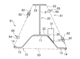
- a pulling device 61 having a lever block 64 may be used as an alternative to the warp correction wedge piece 37 at the time of warp correction.
- a pulling device 61 having a lever block 64 may be used as an alternative to the warp correction wedge piece 37 at the time of warp correction.
- the attracting device 61 includes a chain 63, hooks 62 provided on both sides of the chain 63, and a lever block 64 that is provided at an intermediate portion of the chain 63 and winds up the chain 63 by operating the lever 65.
- the chains 63 of the two attracting devices 61 are connected via the hooks 62 to form an annular shape. And after winding the two attracting devices 61 formed in this ring shape around the cross-sectional outer side orthogonal to the longitudinal direction of the steel material 1 for underground continuous walls, the chain 63 is wound up by the lever 65 operation.
- the steel sheet pile 10 and the H-shaped steel 20 may be deformed in opposite directions by mechanical means such as a robot arm at the time of correcting warpage or bending. Even in this case, welding is performed after the steel sheet pile 10 and the H-section steel 20 are welded along the longitudinal direction while the deformed state is maintained to perform a correction process for bending and warping of the steel sheet pile 10. Therefore, the deformation amount of bending and warping of the steel sheet pile 10 constituting the steel material 1 for underground continuous wall after welding is reduced.
- the steel sheet pile 10 having a substantially curved curved shape in the right direction in the drawing and the substantially convex shape in the left direction in the drawing.
- the combination of what each has the curve of the direction opposite to illustration may be sufficient.
- the steel sheet pile 10 having a warp curved in a substantially upward direction and a warp curved in a substantially convex shape in a downward direction in a side view.
- the combination of what each has the curvature of the opposite direction to illustration may be sufficient.
- positioned on the web part 11 of the steel sheet pile 10 at the time of the assembly process of the steel material 1 for underground continuous walls a bending smaller than this in the same direction as the bending of the steel sheet pile 10 is carried out. What has it may be arrange
- the H-section steel 20 arranged on the web part 11 of the steel sheet pile 10 at the time of assembling the steel material 1 for the underground continuous wall is bent in the opposite direction to the bending or warping of the steel sheet pile 10 for the following reasons. It is desirable to arrange the one having warp from the viewpoint of on-site processing management.
- the H-section steel 20 having a bend or warp smaller than these in the same direction as the bend or warp of the steel sheet pile 10 is arranged, for example, the H-shaped steel 20 having a bend larger than this in the same direction as the bend of the steel sheet pile 10. Cannot be arranged on the steel sheet pile 10, and the shape of the H-section steel 20 that can be applied is restricted.
- the H-section steel 20 is bent in the direction opposite to the bending and warping of the steel sheet pile 10, the H-section steel 20 is bent in any direction at the preparation stage before the arrangement, and warps. Even if it has, the bending and warping of the H-section steel 20 can be reversed only by rotating the H-section steel 20 by 180 ° about the horizontal axis or the vertical axis. The restrictions due to the shape can be greatly reduced, and the present invention can be easily applied. Further, the steel sheet pile 10 is largely corrected when the steel sheet pile 10 is bent, bent in the direction opposite to the warp, and the H-shaped steel 20 having the warp is disposed.
- the assembly processing of the steel material 1 for the underground continuous wall is performed as follows. Also good. First, at the time of material acceptance inspection of the plurality of steel sheet piles 10 and the H-shaped steel 20, the material number is written for each steel material, and then the bending and warping of each steel material are measured. Then, when assembling the steel material 1 for underground continuous wall, as the H-section steel 20 arranged on the web part 11 of the steel sheet pile 10, a bending smaller than this is made in the opposite direction or the same direction as the bending of the steel sheet pile 10.
- the steel material 1 for underground continuous wall was assembled from a steel sheet pile 10 having the dimensions, bending deformation rate, and warpage deformation rate of the conditions shown in Table 1 below by applying the present invention.
- the steel sheet pile 10 uses a hat-shaped steel having an effective width of 900 mm, a height of 230 mm, a cross-sectional area of 110 cm 2 , a cross-sectional secondary moment of 9430 cm 3 per sheet of 10H, and a H-section steel 20
- the steel sheet pile 10 and the H-section steel 20 have the same length in the longitudinal direction.
- a steel sheet pile 10 having a bending deformation rate and a warp deformation rate comparable to those of the steel sheet pile 10 in the opposite direction to the warp was used.
- the leg length of the welded part by welding performed in the main welding process was set to 7 mm that is generally used.
- the length in Table 1 is the length of the entire length of the member
- the welding rate is the ratio of the welding length to the length of the total length of the member
- the bending deformation rate and the warping deformation rate are shown in FIG. 2A.
- the maximum deformation amount ⁇ due to bending or warping of the steel sheet pile 10 or the H-section steel 20 is divided by the length L between both ends in the longitudinal direction.
- the allowable value is a numerical value obtained by dividing the deformation tolerance ( ⁇ ) for bending or warping of the hat-type steel sheet pile described in JIS A5523 by the length L, and the allowable value of the bending deformation rate.
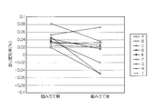
- FIG. 12A shows a change in the bending deformation rate before and after assembling the steel material 1 for underground continuous wall
- FIG. 12B shows a change in the warp deformation rate before and after the assembly.
- the bending as shown in FIG. 12A, the bending in 7 cases out of 9 cases is the same or smaller than that before assembling. Further, as shown in Table 1, the bending is assembled in all examples in 9 cases. It can be confirmed later that it is within the allowable value of JIS. Moreover, although the example of the numbers F and G exceeded the allowable value of JIS before the assembly, it can be confirmed that it is within the allowable value after the assembly. As shown in Table 1 and FIG.
- a pair of flange portions are provided at both ends of the web portion, an arm portion is provided at the distal end of the flange portion, and a joint portion is provided at the distal end of the arm portion.
- the steel sheet pile and the H-shaped steel may be deformed in opposite directions so that the H-shaped steel having a small warpage is further arranged and the bending and warping of the steel sheet pile are corrected.
- the H-shaped steel arranged on the web portion of the steel sheet pile is partially fixed to the steel sheet pile, and the steel sheet pile and the H-shaped steel are fixed.
- the steel sheet pile and the H shape are driven by driving a wedge piece between the bending correction jig fixed to the steel sheet pile and the side surface of the H shape steel.
- the steel may be deformed in opposite directions.
- the H-shaped steel arranged on the web portion of the steel sheet pile is partially fixed to the steel sheet pile, and the steel sheet pile and the H-shaped steel are fixed.
- a wedge piece In a portion spaced in the longitudinal direction from the portion (fixed position), a wedge piece is driven between the bend correction jig fixed to the steel sheet pile and the side surface of the H-shaped steel, and the warp fixed to the steel sheet pile
- the steel sheet pile and the H-shaped steel may be deformed in opposite directions by driving another wedge piece between the straightening jig and the inner surface of one flange portion of the H-shaped steel.
- the wedge piece may be driven multiple times so as to be separated from the fixing portion (fixed position) of the steel sheet pile and the H-shaped steel in the longitudinal direction.
- the bending correction jig and / or the warp correction jig is The bend correction jig and / or the warp correction jig removed from the steel sheet pile may be used when the wedge piece is driven next.
- the present invention in the steel material for underground continuous wall in which a steel sheet pile having a substantially hat-shaped cross section and an H-shaped steel are combined, by reducing the bending and warping of the steel sheet pile after the assembly, It is possible to provide a method for manufacturing a steel material for underground continuous walls that can suppress the occurrence of straightening work and can facilitate on-site work without depending on the skill of a skilled worker. Therefore, industrial applicability is great.
Landscapes
- Engineering & Computer Science (AREA)
- Structural Engineering (AREA)
- Chemical & Material Sciences (AREA)
- Composite Materials (AREA)
- Life Sciences & Earth Sciences (AREA)
- General Life Sciences & Earth Sciences (AREA)
- Mining & Mineral Resources (AREA)
- Paleontology (AREA)
- Civil Engineering (AREA)
- General Engineering & Computer Science (AREA)
- Bulkheads Adapted To Foundation Construction (AREA)
Abstract
Description
本願は、2009年2月12日に、日本に出願された特願2009-030310号に基づき優先権を主張し、その内容をここに援用する。
X≦(L-10)×0.10(%)+0.012 ・・・ (1)
Y≦(L-10)×0.20(%)+0.025 ・・・ (2)
(1)本発明の第1の態様は、鋼矢板のウエブ部とH形鋼のフランジ部とを対面させる対面工程と;
前記鋼矢板と前記H形鋼とを第1固定位置で固定する第1固定工程と;前記鋼矢板と前記H形鋼とを変形させることにより、前記鋼矢板の幅方向の曲がりと前記H形鋼の幅方向の曲がりとを矯正する曲がり矯正工程と;前記鋼矢板と前記H形鋼とを、前記第1固定位置から前記鋼矢板の長手方向に離間した第2固定位置で固定する第2固定工程と;前記鋼矢板と前記H形鋼とを前記鋼矢板の長手方向に沿って溶接する溶接工程と;を備える地中連続壁用鋼材の製造方法である。

{(L-10)×0.10×0.01+12×0.001}/L ・・・ (3)
{(L-10)×0.20×0.01+25×0.001}/L ・・・ (4)
上記地中連続壁用鋼材の製造方法では、上記ウエブ部の板厚方向に反りを更に有する上記鋼矢板の当該ウエブ部上に、当該鋼矢板の反りと反対方向の反り又は同一方向にこれよりも小さい反りを更に有する上記H形鋼を配置し、上記鋼矢板の曲がり及び反りが矯正されるように、上記鋼矢板及び上記H形鋼をそれぞれ反対方向に変形させてもよい。
上記地中連続壁用鋼材の製造方法では、上記鋼矢板のウエブ部上に配置された上記H形鋼を当該鋼矢板に対して一部で固定し、上記鋼矢板とH形鋼との固定部(固定位置)から長手方向に離間した部位において、上記鋼矢板に固定された曲がり矯正治具と上記H形鋼の側面との間に楔片を打ち込むことによって、上記鋼矢板及び上記H形鋼をそれぞれ反対方向に変形させてもよい。
上記地中連続壁用鋼材の製造方法では、上記鋼矢板のウエブ部上に配置された上記H形鋼を当該鋼矢板に対して一部で固定し、上記鋼矢板とH形鋼との固定部(固定位置)から長手方向に離間した部位において、上記鋼矢板に固定された曲がり矯正治具と上記H形鋼の側面との間に楔片を打ち込むとともに、上記鋼矢板に固定された反り矯正治具と上記H形鋼の一方のフランジ部内面との間に他の楔片を打ち込むことによって、上記鋼矢板及び上記H形鋼をそれぞれ反対方向に変形させてもよい。
上記地中連続壁用鋼材の製造方法では、上記鋼矢板とH形鋼との固定部(固定位置)から長手方向に離間するように複数回に亘って上記楔片の打ち込みを行ってもよい。
上記地中連続壁用鋼材の製造方法では、上記楔片が打ち込まれた部位において上記H形鋼を上記鋼矢板に対して固定した後に上記曲がり矯正治具及び/又は上記反り矯正治具を上記鋼矢板から取り外し、上記取り外した曲がり矯正治具及び/又は反り矯正治具を次の上記楔片の打ち込み時に用いてもよい。
5 地中連続壁体
10 鋼矢板
11 ウエブ部
12 フランジ部
13 アーム部
14 継手部
20 H形鋼
21 ウエブ部
22、23 フランジ部
27 隅肉溶接
31 曲がり矯正治具
33 反り矯正治具
35 曲がり矯正用楔片
37 反り矯正用楔片
41 点溶接
43 固定部(固定位置)
50 Z型鋼矢板
51 ウエブ部
52 アーム部
Claims (12)
- 鋼矢板のウエブ部とH形鋼のフランジ部とを対面させる対面工程と;
前記鋼矢板と前記H形鋼とを第1固定位置で固定する第1固定工程と;
前記鋼矢板と前記H形鋼とを変形させることにより、前記鋼矢板の幅方向の曲がりと前記H形鋼の幅方向の曲がりとを矯正する曲がり矯正工程と;
前記鋼矢板と前記H形鋼とを、前記第1固定位置から前記鋼矢板の長手方向に離間した第2固定位置で固定する第2固定工程と;
前記鋼矢板と前記H形鋼とを前記鋼矢板の長手方向に沿って溶接する溶接工程と;
を備えることを特徴とする地中連続壁用鋼材の製造方法。 - 前記曲がり矯正工程は、
前記第1固定位置から前記鋼矢板の長手方向に離間した位置において、前記鋼矢板に第1の曲がり矯正治具を取り付ける第1の曲がり矯正治具取り付け工程と;
前記第1の曲がり矯正治具と前記H形鋼の側面との間に第1の曲がり矯正楔片を打ち込む第1の曲がり矯正楔片打ち込み工程と;
を備えることを特徴とする請求項1に記載の地中連続壁用鋼材の製造方法。 - 前記第1の曲がり矯正治具は、前記鋼矢板に溶接により取り付けられること
を特徴とする請求項2に記載の地中連続壁用鋼材の製造方法。 - 前記第1の曲がり矯正治具が取り付けられた位置から前記鋼矢板の長手方向に離間した位置において、前記鋼矢板に第2の曲がり矯正治具を取り付ける第2の曲がり矯正治具取り付け工程と;
前記第2の曲がり矯正治具と前記H形鋼の側面との間に第2の曲がり矯正楔片を打ち込む第2の曲がり矯正楔片打ち込み工程と;
を更に備えることを特徴とする請求項2に記載の地中連続壁用鋼材の製造方法。 - 前記第2の曲がり矯正治具が、前記鋼矢板から取り外された前記第1の曲がり矯正治具であること
を特徴とする請求項4に記載の地中連続壁用鋼材の製造方法。 - 前記鋼矢板と前記H形鋼とを変形させることにより、前記鋼矢板の厚さ方向の反りと前記H形鋼の厚さ方向の反りとを矯正する反り矯正工程
を更に備えることを特徴とする請求項1~5のいずれか一項に記載の地中連続壁用鋼材の製造方法。 - 前記反り矯正工程は、
前記第1固定位置から前記鋼矢板の長手方向に離間した位置において、前記鋼矢板に第1の反り矯正治具を取り付ける第1の反り矯正治具取り付け工程と;
前記第1の反り矯正治具と前記H形鋼の前記フランジ部の上面との間に第1の反り矯正楔片を打ち込む第1の反り矯正楔片打ち込み工程と;
を備えることを特徴とする請求項6に記載の地中連続壁用鋼材の製造方法。 - 前記第1の反り矯正治具は、前記鋼矢板に溶接により取り付けられること
を特徴とする請求項7に記載の地中連続壁用鋼材の製造方法。 - 前記第1の反り矯正治具が取り付けられた位置から前記鋼矢板の長手方向に離間した位置において、前記鋼矢板に第2の反り矯正治具を取り付ける第2の反り矯正治具取り付け工程と;
前記第2の反り矯正治具と前記H形鋼の前記フランジ部の上面との間に第2の反り矯正楔片を打ち込む第2の反り矯正楔片打ち込み工程と;
を更に備えることを特徴とする請求項7に記載の地中連続壁用鋼材の製造方法。 - 前記第2の反り矯正治具が、前記鋼矢板から取り外された前記第1の反り矯正治具であること
を特徴とする請求項9に記載の地中連続壁用鋼材の製造方法。 - 前記鋼矢板は、ハット型鋼矢板又は断面略ハット型形状となるように連結された二枚のZ型鋼矢板から構成されること
を特徴とする請求項1に記載の地中連続壁用鋼材の製造方法。 - 前記第1固定工程は、
前記鋼矢板に固定用反り矯正治具を固定する工程と;
前記固定用反り矯正治具と前記H形鋼の前記フランジ部との間に固定用楔片を打ち込む工程と;
を備えることを特徴とする請求項1に記載の地中連続壁用鋼材の製造方法。
Priority Applications (3)
| Application Number | Priority Date | Filing Date | Title |
|---|---|---|---|
| JP2010550430A JP4846874B2 (ja) | 2009-02-12 | 2010-01-19 | 地中連続壁用鋼材の製造方法 |
| HK12102401.5A HK1161903B (en) | 2009-02-12 | 2010-01-19 | Method of manufacturing steel material for underground continuous wall |
| CN201080005877.XA CN102301071B (zh) | 2009-02-12 | 2010-01-19 | 地下连续墙用钢材的制造方法 |
Applications Claiming Priority (2)
| Application Number | Priority Date | Filing Date | Title |
|---|---|---|---|
| JP2009-030310 | 2009-02-12 | ||
| JP2009030310 | 2009-02-12 |
Publications (1)
| Publication Number | Publication Date |
|---|---|
| WO2010092746A1 true WO2010092746A1 (ja) | 2010-08-19 |
Family
ID=42561595
Family Applications (1)
| Application Number | Title | Priority Date | Filing Date |
|---|---|---|---|
| PCT/JP2010/000273 Ceased WO2010092746A1 (ja) | 2009-02-12 | 2010-01-19 | 地中連続壁用鋼材の製造方法 |
Country Status (4)
| Country | Link |
|---|---|
| JP (1) | JP4846874B2 (ja) |
| CN (1) | CN102301071B (ja) |
| TW (1) | TWI398568B (ja) |
| WO (1) | WO2010092746A1 (ja) |
Cited By (3)
| Publication number | Priority date | Publication date | Assignee | Title |
|---|---|---|---|---|
| JP2016204953A (ja) * | 2015-04-21 | 2016-12-08 | 鹿島建設株式会社 | 土留め方法 |
| CN110001039A (zh) * | 2019-04-30 | 2019-07-12 | 深圳市盛波光电科技有限公司 | 一种偏光板片材翘曲矫正方法 |
| EP3640400A1 (en) * | 2018-10-19 | 2020-04-22 | J.D. Fields & Company, Inc. | Combined wall piling system |
Citations (5)
| Publication number | Priority date | Publication date | Assignee | Title |
|---|---|---|---|---|
| JPS58132659U (ja) * | 1982-03-04 | 1983-09-07 | 川崎重工業株式会社 | 部材の組立ジグ |
| JPH04149311A (ja) * | 1990-10-11 | 1992-05-22 | Fudo Constr Co Ltd | 鋼製地下連続壁における接合構造 |
| JPH0584490U (ja) * | 1992-02-07 | 1993-11-16 | 利光 中村 | つば部付き鉄板の位置合わせ装置 |
| JP2002212943A (ja) * | 2001-01-19 | 2002-07-31 | Sumitomo Metal Ind Ltd | 地中連続壁用鋼材および地中連続壁 |
| JP2007054838A (ja) * | 2005-08-22 | 2007-03-08 | Jfe Steel Kk | 腕部を有するu型鋼矢板のプレス矯正方法 |
Family Cites Families (3)
| Publication number | Priority date | Publication date | Assignee | Title |
|---|---|---|---|---|
| JPS58132659A (ja) * | 1982-02-03 | 1983-08-08 | Mitsubishi Heavy Ind Ltd | 潜水装置 |
| DE69638361D1 (de) * | 1995-09-29 | 2011-06-09 | Sumitomo Metal Ind | Verfahren zur Korrektur von U-förmigen Stahlspundbohlen |
| JP2005127033A (ja) * | 2003-10-24 | 2005-05-19 | Sumitomo Metal Ind Ltd | 地中連続壁用鋼材の製造方法 |
-
2010
- 2010-01-19 JP JP2010550430A patent/JP4846874B2/ja active Active
- 2010-01-19 WO PCT/JP2010/000273 patent/WO2010092746A1/ja not_active Ceased
- 2010-01-19 CN CN201080005877.XA patent/CN102301071B/zh active Active
- 2010-01-25 TW TW099101936A patent/TWI398568B/zh not_active IP Right Cessation
Patent Citations (5)
| Publication number | Priority date | Publication date | Assignee | Title |
|---|---|---|---|---|
| JPS58132659U (ja) * | 1982-03-04 | 1983-09-07 | 川崎重工業株式会社 | 部材の組立ジグ |
| JPH04149311A (ja) * | 1990-10-11 | 1992-05-22 | Fudo Constr Co Ltd | 鋼製地下連続壁における接合構造 |
| JPH0584490U (ja) * | 1992-02-07 | 1993-11-16 | 利光 中村 | つば部付き鉄板の位置合わせ装置 |
| JP2002212943A (ja) * | 2001-01-19 | 2002-07-31 | Sumitomo Metal Ind Ltd | 地中連続壁用鋼材および地中連続壁 |
| JP2007054838A (ja) * | 2005-08-22 | 2007-03-08 | Jfe Steel Kk | 腕部を有するu型鋼矢板のプレス矯正方法 |
Cited By (4)
| Publication number | Priority date | Publication date | Assignee | Title |
|---|---|---|---|---|
| JP2016204953A (ja) * | 2015-04-21 | 2016-12-08 | 鹿島建設株式会社 | 土留め方法 |
| EP3640400A1 (en) * | 2018-10-19 | 2020-04-22 | J.D. Fields & Company, Inc. | Combined wall piling system |
| US10995467B2 (en) | 2018-10-19 | 2021-05-04 | J.D. Fields & Company, Inc. | Combined wall piling system |
| CN110001039A (zh) * | 2019-04-30 | 2019-07-12 | 深圳市盛波光电科技有限公司 | 一种偏光板片材翘曲矫正方法 |
Also Published As
| Publication number | Publication date |
|---|---|
| CN102301071B (zh) | 2014-01-29 |
| JPWO2010092746A1 (ja) | 2012-08-16 |
| HK1161903A1 (en) | 2012-08-10 |
| JP4846874B2 (ja) | 2011-12-28 |
| TW201033440A (en) | 2010-09-16 |
| CN102301071A (zh) | 2011-12-28 |
| TWI398568B (zh) | 2013-06-11 |
Similar Documents
| Publication | Publication Date | Title |
|---|---|---|
| JP4943218B2 (ja) | 地中連続壁用鋼材、地中連続壁および地中連続壁の構築方法 | |
| US9512590B2 (en) | Combined steel sheet pile, diaphragm wall, and method of disassembling combined steel sheet pile | |
| EP2672012B1 (en) | A mono-pile type foundation structure for connecting steel pipe pile and steel sleeve pipe | |
| JP2005299202A (ja) | 鋼矢板とそれを用いた土留め構造及び土留め構造の構築方法 | |
| JP4903744B2 (ja) | 既設の鋼矢板の補強構造、既設の鋼矢板の補強用部材 | |
| WO2011132489A1 (ja) | 組合せ鋼矢板壁 | |
| WO2012060020A1 (ja) | 鋼管補剛ブレース材およびその製造方法 | |
| JP4846874B2 (ja) | 地中連続壁用鋼材の製造方法 | |
| JP5413541B2 (ja) | 組合せ鋼矢板、地中連続壁、及び組合せ鋼矢板の再利用方法 | |
| WO2011065527A1 (ja) | 鋼管矢板継手構造、鋼管矢板基礎、及び鋼管矢板基礎の構築方法 | |
| JP5163246B2 (ja) | 地中連続壁及びその構築方法 | |
| JP5867326B2 (ja) | 鋼矢板及びこれを用いた壁体 | |
| JP2010261219A (ja) | 鋼管補剛ブレース材およびその製造方法 | |
| WO2012057359A1 (ja) | 鋼矢板及び該鋼矢板によって形成された鋼矢板壁 | |
| WO2015107816A1 (ja) | 組合せ鋼矢板連設用治具及び組合せ鋼矢板連設方法 | |
| HK1161903B (en) | Method of manufacturing steel material for underground continuous wall | |
| JP4358709B2 (ja) | 遮水用鋼管矢板パネル | |
| JP2011111873A (ja) | 鋼管矢板構造物およびその施工方法 | |
| JP4823865B2 (ja) | 組合せ鋼矢板及び鋼矢板の製造方法 | |
| JP6885823B2 (ja) | ボトム筋湾曲是正方法および戴置不良是正方法 | |
| JP4798251B2 (ja) | 組合せ鋼矢板および該組合せ鋼矢板を用いた鋼矢板壁 | |
| JP2021123921A (ja) | 鋼矢板の継手構造及び鋼矢板構造体 | |
| JP5825232B2 (ja) | 組合せ鋼製壁および組合せ鋼製壁の設計方法 | |
| JP5635383B2 (ja) | 既設杭の位置調整治具 | |
| JP5664402B2 (ja) | 組合せ鋼矢板及び該組合せ鋼矢板によって形成された鋼矢板壁 |
Legal Events
| Date | Code | Title | Description |
|---|---|---|---|
| WWE | Wipo information: entry into national phase |
Ref document number: 201080005877.X Country of ref document: CN |
|
| 121 | Ep: the epo has been informed by wipo that ep was designated in this application |
Ref document number: 10741026 Country of ref document: EP Kind code of ref document: A1 |
|
| ENP | Entry into the national phase |
Ref document number: 2010550430 Country of ref document: JP Kind code of ref document: A |
|
| NENP | Non-entry into the national phase |
Ref country code: DE |
|
| 122 | Ep: pct application non-entry in european phase |
Ref document number: 10741026 Country of ref document: EP Kind code of ref document: A1 |