WO2010087352A1 - アライメント方法、露光方法、電子デバイスの製造方法、アライメント装置及び露光装置 - Google Patents
アライメント方法、露光方法、電子デバイスの製造方法、アライメント装置及び露光装置 Download PDFInfo
- Publication number
- WO2010087352A1 WO2010087352A1 PCT/JP2010/051006 JP2010051006W WO2010087352A1 WO 2010087352 A1 WO2010087352 A1 WO 2010087352A1 JP 2010051006 W JP2010051006 W JP 2010051006W WO 2010087352 A1 WO2010087352 A1 WO 2010087352A1
- Authority
- WO
- WIPO (PCT)
- Prior art keywords
- substrate
- alignment
- hole
- pattern
- exposure
- Prior art date
- Legal status (The legal status is an assumption and is not a legal conclusion. Google has not performed a legal analysis and makes no representation as to the accuracy of the status listed.)
- Ceased
Links
Images


Classifications
-
- G—PHYSICS
- G03—PHOTOGRAPHY; CINEMATOGRAPHY; ANALOGOUS TECHNIQUES USING WAVES OTHER THAN OPTICAL WAVES; ELECTROGRAPHY; HOLOGRAPHY
- G03F—PHOTOMECHANICAL PRODUCTION OF TEXTURED OR PATTERNED SURFACES, e.g. FOR PRINTING, FOR PROCESSING OF SEMICONDUCTOR DEVICES; MATERIALS THEREFOR; ORIGINALS THEREFOR; APPARATUS SPECIALLY ADAPTED THEREFOR
- G03F7/00—Photomechanical, e.g. photolithographic, production of textured or patterned surfaces, e.g. printing surfaces; Materials therefor, e.g. comprising photoresists; Apparatus specially adapted therefor
- G03F7/70—Microphotolithographic exposure; Apparatus therefor
- G03F7/708—Construction of apparatus, e.g. environment aspects, hygiene aspects or materials
- G03F7/7085—Detection arrangement, e.g. detectors of apparatus alignment possibly mounted on wafers, exposure dose, photo-cleaning flux, stray light, thermal load
-
- G—PHYSICS
- G03—PHOTOGRAPHY; CINEMATOGRAPHY; ANALOGOUS TECHNIQUES USING WAVES OTHER THAN OPTICAL WAVES; ELECTROGRAPHY; HOLOGRAPHY
- G03F—PHOTOMECHANICAL PRODUCTION OF TEXTURED OR PATTERNED SURFACES, e.g. FOR PRINTING, FOR PROCESSING OF SEMICONDUCTOR DEVICES; MATERIALS THEREFOR; ORIGINALS THEREFOR; APPARATUS SPECIALLY ADAPTED THEREFOR
- G03F7/00—Photomechanical, e.g. photolithographic, production of textured or patterned surfaces, e.g. printing surfaces; Materials therefor, e.g. comprising photoresists; Apparatus specially adapted therefor
- G03F7/70—Microphotolithographic exposure; Apparatus therefor
- G03F7/70691—Handling of masks or workpieces
- G03F7/70775—Position control, e.g. interferometers or encoders for determining the stage position
-
- G—PHYSICS
- G03—PHOTOGRAPHY; CINEMATOGRAPHY; ANALOGOUS TECHNIQUES USING WAVES OTHER THAN OPTICAL WAVES; ELECTROGRAPHY; HOLOGRAPHY
- G03F—PHOTOMECHANICAL PRODUCTION OF TEXTURED OR PATTERNED SURFACES, e.g. FOR PRINTING, FOR PROCESSING OF SEMICONDUCTOR DEVICES; MATERIALS THEREFOR; ORIGINALS THEREFOR; APPARATUS SPECIALLY ADAPTED THEREFOR
- G03F7/00—Photomechanical, e.g. photolithographic, production of textured or patterned surfaces, e.g. printing surfaces; Materials therefor, e.g. comprising photoresists; Apparatus specially adapted therefor
- G03F7/70—Microphotolithographic exposure; Apparatus therefor
- G03F7/70691—Handling of masks or workpieces
- G03F7/70791—Large workpieces, e.g. glass substrates for flat panel displays or solar panels
-
- G—PHYSICS
- G03—PHOTOGRAPHY; CINEMATOGRAPHY; ANALOGOUS TECHNIQUES USING WAVES OTHER THAN OPTICAL WAVES; ELECTROGRAPHY; HOLOGRAPHY
- G03F—PHOTOMECHANICAL PRODUCTION OF TEXTURED OR PATTERNED SURFACES, e.g. FOR PRINTING, FOR PROCESSING OF SEMICONDUCTOR DEVICES; MATERIALS THEREFOR; ORIGINALS THEREFOR; APPARATUS SPECIALLY ADAPTED THEREFOR
- G03F9/00—Registration or positioning of originals, masks, frames, photographic sheets or textured or patterned surfaces, e.g. automatically
- G03F9/70—Registration or positioning of originals, masks, frames, photographic sheets or textured or patterned surfaces, e.g. automatically for microlithography
- G03F9/7003—Alignment type or strategy, e.g. leveling, global alignment
- G03F9/7007—Alignment other than original with workpiece
- G03F9/7015—Reference, i.e. alignment of original or workpiece with respect to a reference not on the original or workpiece
-
- G—PHYSICS
- G03—PHOTOGRAPHY; CINEMATOGRAPHY; ANALOGOUS TECHNIQUES USING WAVES OTHER THAN OPTICAL WAVES; ELECTROGRAPHY; HOLOGRAPHY
- G03F—PHOTOMECHANICAL PRODUCTION OF TEXTURED OR PATTERNED SURFACES, e.g. FOR PRINTING, FOR PROCESSING OF SEMICONDUCTOR DEVICES; MATERIALS THEREFOR; ORIGINALS THEREFOR; APPARATUS SPECIALLY ADAPTED THEREFOR
- G03F9/00—Registration or positioning of originals, masks, frames, photographic sheets or textured or patterned surfaces, e.g. automatically
- G03F9/70—Registration or positioning of originals, masks, frames, photographic sheets or textured or patterned surfaces, e.g. automatically for microlithography
- G03F9/7088—Alignment mark detection, e.g. TTR, TTL, off-axis detection, array detector, video detection
Definitions
- the present invention relates to an alignment technique for aligning a belt-shaped substrate and a pattern member provided with a pattern to be exposed on the substrate, and an exposure technique using the alignment technique.
- a glass substrate or a resin substrate used for a flat panel display (FPD) such as LCD, PDP, or organic electroluminescence tends to increase in size in response to a demand for an increase in screen size.
- An exposure apparatus that exposes a circuit pattern of a mask onto a glass substrate or a resin substrate is increased in size in accordance with the increase in size of the glass substrate or the resin substrate.
- Patent Document 2 discloses an exposure apparatus that exposes a large glass substrate. This exposure apparatus discloses a technique for obtaining a baseline amount which is a relative position between a mask and an off-axis type alignment detection system using a reference member. After measuring the baseline amount, the alignment detection system detects an alignment mark formed on the glass substrate.
- the projection exposure apparatus disclosed in Patent Document 1 does not disclose an alignment camera or the like for observing the position of the belt-like substrate during the transfer of the belt-like substrate wound in a roll shape. If the technique related to the baseline measurement and the alignment mark detection disclosed in Patent Document 2 is applied to Patent Document 1, a belt-like substrate is continuously present in the transfer direction, so that the reference member is detected. In this case, detection must be performed through a belt-like substrate. However, if mark detection is performed via a strip-shaped substrate, it is affected by substrate distortion or thickness non-uniformity, and there is a problem that mark detection cannot be performed with high accuracy.
- aspects of the present invention provide an alignment method, an alignment apparatus, an exposure method, an exposure apparatus, and a device manufacture that can perform high-precision alignment between a belt-shaped substrate and a pattern member provided with a pattern exposed on the substrate. It aims to provide a method.
- the alignment device in an alignment method for aligning a belt-shaped substrate and a pattern member provided with a pattern exposed on the substrate, the alignment device is provided on a stage device that holds and moves the substrate. Detecting the first information related to the relative position between the reference member and the pattern member through a through hole provided in the substrate, detecting the second information related to the position of the alignment mark provided on the substrate, A step of detecting third information on the relative position between the detector for detecting the position of the alignment mark and the reference member through the through hole; and a step of driving the stage device based on the first, second and third information. are provided.
- the alignment between the substrate and the pattern member is performed using the alignment method of the first aspect of the present invention.
- an exposure method comprising a step of performing exposure and a step of irradiating the substrate, which has been aligned with the pattern member, with exposure light through the pattern.
- a step of transferring a pattern to a substrate coated with a photosensitive agent, and a photosensitive agent on the substrate to which the pattern is transferred is provided.
- a device manufacturing method comprising: a step of developing to form a transfer pan layer having an uneven shape corresponding to a pattern; and a step of processing a substrate through the transfer pattern layer.
- a stage device that holds and moves the belt-shaped substrate.
- a reference member disposed on the stage device, a first detector for detecting first information regarding a relative position between the reference member and the pattern member through a through-hole provided in the substrate, and an alignment provided on the substrate
- a second detector for detecting second information relating to the position of the mark
- a third detector for detecting third information relating to the relative position of the second detector and the reference member via the through hole
- a driving mechanism for driving the stage device based on the third information
- the alignment apparatus in the exposure apparatus that exposes the pattern provided on the pattern member onto the belt-shaped substrate, the alignment apparatus according to the fourth aspect of the present invention that aligns the substrate and the pattern member.
- An exposure apparatus is provided that includes an irradiation apparatus that irradiates exposure light through a pattern onto a substrate that has been aligned with respect to the pattern member.
- alignment between the belt-shaped substrate and the pattern member provided with the pattern exposed on the substrate can be performed with high accuracy.
- (A) is a schematic plan view which shows the exposure apparatus EX of this embodiment.
- (B) is a schematic side view of the exposure apparatus EX. It is the conceptual side view which expanded the range shown by B of FIG.1 (b). It is the conceptual diagram which showed another Example of the substrate stage FBS which supports the strip
- (A) is a schematic plan view which shows the substrate stage FBS of this embodiment.
- (B) is a schematic side view of the exposure apparatus EX. It is the conceptual diagram which showed the state which detects the through-hole TH by rough alignment camera RA.
- (A) is the plane conceptual diagram
- (b) is the schematic side view seen from the X-axis direction.
- (C) has shown the state which detects alignment mark AM (B) of the rear side by alignment camera AC. It is the conceptual side view which showed main operation
- (D) shows a state in which the projection image by the projection optical system PL has reached one end of the exposure area EA.
- (E) shows a state in which the exposure area EA has been exposed and the substrate stage FBS has been lowered. It is a flowchart from the detection of through-hole TH by rough alignment camera RA to the end of exposure. It is the conceptual side view which showed main operation
- (A) has shown the state which alignment camera AC2 detects the board
- (B) has shown the state which alignment camera AC1 detects the board
- (C) shows a state in which the AIS image sensor 99 detects the mask side AIS mark 91 and the substrate side AIS mark 93 through the through hole TH. It is the conceptual side view which showed main operation
- (D) shows a state in which the projection image by the projection optical system PL has reached one end of the exposure area EA.
- (E) shows a state in which the exposure area EA has been exposed and the substrate stage FBS has been lowered.
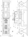
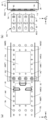
- FIG. 1A is a schematic plan view showing the exposure apparatus EX of the present embodiment, and a portion below the belt-like substrate FB is drawn to help understanding.
- FIG. 1B is a schematic side view of the exposure apparatus EX.
- the exposure apparatus EX includes a supply roller FR that supplies a strip-shaped substrate FB and a take-up roller WR that winds the strip-shaped substrate FB.
- the supply roller FR and the take-up roller WR can transfer the belt-like substrate FB in the direction of the arrow.
- the belt-like substrate FB is a thin resin film that can be wound into a roll.
- the band-shaped substrate FB is a substrate that is sufficiently thin with respect to its area and has flexibility.
- the strip-shaped substrate FB has a length of 100 meters in the X-axis direction, a width of 1 mail in the Y-axis direction, and a thickness of 100 microns, for example.
- the band-shaped substrate FB is made of polyethylene resin, polypropylene resin, polyester resin, ethylene vinyl copolymer resin, polyvinyl chloride resin, cellulose resin, polyamide resin, polyimide resin, polycarbonate resin, polystyrene resin, vinyl acetate resin. Can be used.
- the exposure apparatus EX includes a mask stage MST that supports a mask M on which a pattern is formed, and a substrate stage FBS that supports a strip-shaped substrate FB.
- the mask M is a member in which a circuit pattern or the like is drawn on quartz glass.
- the exposure apparatus EX includes a plurality of laser interferometers LM that detect positions of the mask stage MST that supports the mask M in the X-axis direction and the Y-axis direction, and the X-axis direction and Y of the substrate stage FBS that supports the strip-shaped substrate FB. And a plurality of laser interferometers MM for detecting positions in the axial direction.
- Mask stage MST can move a long stroke in the X-axis direction and can move a short stroke in the Y-axis direction by a linear motor (not shown).
- the substrate stage FBS can move a long stroke in the X-axis direction and can move a short stroke in the Y-axis direction.
- FIG. 1B only one laser interferometer LMx and one laser interferometer MMx for detecting the position in the X-axis direction are drawn.
- the exposure apparatus EX has a projection optical system PL that projects an image of the pattern of the mask M illuminated with the exposure light EL by an illumination optical system (not shown) onto a strip-shaped substrate FB supported by the substrate stage FBS.
- the projection image PI of the pattern of the mask M is shown in a trapezoidal shape
- the exposure apparatus EX is arranged in three rows arranged in two rows in the X-axis direction and alternately arranged in the Y-axis direction. It has an optical system PL.
- FIG. 1B shows one projection optical system PL.
- the mask M supported by the mask stage MST and the belt-like substrate FB supported by the substrate stage FBS are arranged in a conjugate positional relationship via the projection optical system PL.
- the exposure apparatus EX is provided with a punch 10 for forming a predetermined through hole TH in a strip-shaped substrate FB.
- the punch 10 is disposed on the supply roller FR side.
- the punch 10 may be one that presses a mold to form the through hole TH in the belt-like substrate FB, or may be one that forms the through hole TH in the belt-like substrate FB with a laser beam or the like.
- the punch 10 of this embodiment opens, for example, four through holes TH in the Y-axis direction.
- the diameter of the through hole TH may be larger than the diameter of the substrate side AIS mark 93 described later.
- the through hole TH is already opened when the strip-shaped substrate FB is attached to the supply roller FR, it is not necessary to provide the punch 10.
- the four through holes TH opened by the punch 10 are formed at positions at both ends of the projection optical system PL in the Y-axis direction and positions at which the trapezoidal projection images PI of the adjacent projection optical systems PL overlap each other.
- the exposure apparatus EX has four alignment cameras AC that detect alignment marks AM provided on the strip-shaped substrate FB adjacent to the projection optical system PL.
- two rough alignment cameras RA that detect the through holes TH provided in the belt-like substrate FB adjacent to the alignment camera AC are provided.
- a plurality of alignment marks AM are already formed around the exposure area EA, which is the irradiation area of the exposure light EL, on the belt-like substrate FB.
- a total of 16 alignment marks AM are formed for each periphery of one exposure area EA.
- the alignment mark is shown as “+”, but it may be a box mark “ ⁇ ”, for example.
- the alignment camera AC in the present embodiment is an off-axis method, and when performing the alignment process, a baseline amount that is a relative position between the mask M and the alignment camera AC is measured.
- FIG. 1B only one alignment camera AC and one rough alignment camera RA are illustrated.
- a mask side AIS mark 91 for baseline measurement is provided on the mask M, and a reference member having a substrate side AIS mark 93 for baseline measurement on the substrate stage FBS. 95 is provided.
- the mask side AIS mark 91 is provided in a predetermined positional relationship with respect to a specific position (for example, the center position) of the mask M.
- the mask side AIS mark 91 and the substrate side AIS mark 93 correspond to each other, and for example, four are provided side by side in the Y-axis direction.
- the exposure apparatus EX is a scanning exposure apparatus that performs scanning exposure by synchronously moving the mask M and the strip-shaped substrate FB with respect to the exposure light EL.
- a projection optical system is used.
- the optical axis direction of PL is the Z-axis direction
- the direction perpendicular to the Z-axis direction is the synchronous movement direction of the mask M
- the strip-shaped substrate FB is the X-axis direction (scanning direction)
- the Z-axis direction and the X-axis direction (scanning direction).
- the direction orthogonal to the Y-axis direction non-scanning direction).
- FIG. 2 is a conceptual side view in which the range indicated by B in FIG. ⁇ Configuration of substrate stage>
- the substrate stage FBS that supports the belt-like substrate FB has a vacuum suction hole 21, and holds the belt-like substrate FB through the vacuum suction hole 21.
- the vacuum suction hole 21 is connected to a vacuum pump (not shown).
- the substrate stage FBS can move a long stroke in the X-axis direction and a short stroke for alignment in the Y-axis direction orthogonal to the scanning direction so as to perform one-dimensional scanning exposure in the X-axis direction.
- a substrate stage moving unit 28 is provided below the stage FBS for moving in the ⁇ Z direction (rotation direction) centered in the X-axis direction, the Y-axis direction, and the Z-axis direction.
- the substrate stage moving unit 28 is controlled by a control device (not shown).
- a state in which the substrate stage FBS is largely moved in the X-axis direction is indicated by a dotted line.
- a 3-point or 4-point height adjustment section 26 is placed on the upper part of the substrate stage moving section 28.
- the height adjusting unit 26 has a stroke of about 10 mm in the Z-axis direction.
- the strip-shaped substrate FB and the substrate stage FBS are moved to several mm until only the strip-shaped substrate FB is transferred and the next exposure area EA moves onto the substrate stage FBS. It is preferable to leave a gap. Therefore, the height adjusting unit 26 has a stroke for forming a gap between the belt-like substrate FB and the substrate stage FBS.
- the height adjustment unit 26 aligns the substrate stage FBS in the optical axis direction (Z-axis direction) in order to match the image plane of the projection optical system PL and the surface of the strip-shaped substrate FB adsorbed to the substrate stage FBS. Move. Also, by moving one or two of the three or four height adjustment units 26, the ⁇ X direction (rotation direction) centered on the X axis direction and the ⁇ Y direction centered on the Y axis direction It is also possible to move the substrate stage FBS in the (rotating direction). Further, instead of adjusting the height of the substrate stage FBS in the Z-axis direction, the height of the substrate FB may be adjusted in the Z-axis direction. In this case, for example, a mechanism for moving the supply roller FR and the take-up roller WR in the Z-axis direction may be provided.
- a reference member 95 is attached to the same surface as the surface of the substrate stage FBS.
- a lens system 97 that collects light that has passed through the reference member 95
- an AIS image sensor 99 that receives the light passing through the lens system 97 are embedded.
- the AIS image sensor 99 is a two-dimensional image element such as a MOS or a CCD.
- FIG. 3 is a conceptual diagram showing another embodiment of the substrate stage FBS that supports the belt-like substrate FB.
- FIG. 3A is a schematic plan view showing the substrate stage FBS of the present embodiment, and a portion below the belt-like substrate FB is drawn to help understanding.
- FIG. 3B is a schematic side view of the exposure apparatus EX.
- the substrate stage FBS that supports the belt-like substrate FB includes the vacuum suction holes 21, but the vacuum suction holes 21 are not necessarily provided.
- a pair of crimping fixing portions 30 may be provided so as to sandwich the exposure area EA in the X-axis direction.
- the crimping fixing portion 30 includes two pairs of piston portions 33 and a pair of crimping plates 35.
- the two pairs of piston portions 33 are disposed in the vicinity of the four corners of the substrate stage FBS, and the pressure plate 35 extending in the Y-axis direction is disposed on the pair of piston portions 33.
- the pair of pressure-bonding plates 35 are arranged so that at least the exposure area EA and the through hole TH are interposed therebetween.
- the pair of pressure-bonding plates 35 pressure-bond the strip-shaped substrate FB to the surface of the substrate stage FBS. Since the strip-shaped substrate FB is long, extra tension may be applied to the strip-shaped substrate FB. There is also a possibility that the supply roller FR and the take-up roller WR may not be synchronized with the movement of the substrate stage FBS. Even in these cases, since the band-shaped substrate FB is pressed against the substrate stage FBS by the pressure plate 35 in the Z-axis direction, there is no possibility that the position of the band-shaped substrate FB is shifted. In addition to the vacuum suction hole 21 provided in the substrate stage FBS, a crimp fixing part 30 may be provided. With such a configuration, the positional deviation of the belt-like substrate FB is further reduced.
- the alignment camera AC detects an alignment mark AM provided on the belt-like substrate FB.
- Four alignment cameras AC are provided side by side in the Y-axis direction so as to face the band-shaped substrate FB between the alternately arranged projection optical systems PL.
- the alignment camera AC includes an alignment light source 81 that emits alignment detection light, a relay lens 82 that extends the detection light emitted from the alignment light source 81, a half mirror 83 provided on the downstream side of the optical path of the relay lens 82, Have The alignment camera AC has an objective lens 84 that irradiates the detection light that has passed through the half mirror 83 onto the belt-like substrate FB.
- the alignment camera AC includes a beam splitter 85 that branches reflected light from the belt-like substrate FB, a high-magnification lens 86 having a high magnification, and a high-magnification imaging device ACC, and a narrow region in the through hole TH. Can be measured with high accuracy.
- the high-magnification imaging device ACC is a two-dimensional image device such as a MOS or a CCD. That is, the alignment camera AC irradiates the alignment mark AM on the belt-like substrate FB via the half mirror 83 and the objective lens 84 by irradiating the detection light, and reflects the reflected light from the alignment mark AM to the half mirror 83 and the beam splitter. The image is captured by the high-magnification imaging device ACC through the lens 85 and the high-magnification lens 86.
- the rough alignment camera RA detects the positions of the four through holes TH provided in the belt-like substrate FB.
- the rough alignment camera RA is provided for the alignment camera AC to detect the substrate-side AIS mark 93 through the through hole TH.
- two or four rough alignment cameras RA are provided in the Y-axis direction so as to face the band-shaped substrate FB between the alternately arranged projection optical systems PL.
- the rough alignment camera RA shares the light source of the alignment camera AC, the configuration from the alignment light source 81 to the objective lens 84 is the same as that of the alignment camera AC.
- the rough alignment camera RA includes a reflection mirror 87 that reflects the reflected light from the band-shaped substrate FB, a low-magnification lens 88 having a low magnification, and a low-magnification imaging device RCC, and has a wide band-shaped substrate FB. The area can be measured.
- the low-magnification imaging device RCC is also a two-dimensional image device such as a MOS or a CCD.
- the rough alignment camera RA irradiates the through-hole TH on the belt-like substrate FB and the periphery thereof through the half mirror 83 and the objective lens 84 by irradiation with detection light. Then, the reflected light from the periphery of the through hole TH is imaged by the low magnification imaging element RCC via the half mirror 83, the low magnification lens 88, and the like.
- FIG. 4 is a conceptual diagram showing a state in which the through hole TH is detected by the rough alignment camera RA.
- 4A is a conceptual plan view thereof
- FIG. 4B is a schematic side view seen from the X-axis direction.
- two rough alignment cameras RA are arranged side by side in the Y-axis direction so as to detect the two through holes TH on both ends of the belt-like substrate FB. Since the four through holes TH are formed at substantially the same position in the X-axis direction, it is not necessary to prepare four rough alignment cameras RA for the four through holes TH, and only one may be prepared.
- the belt-like substrate FB and the substrate stage FBS are separated by a predetermined distance in the Z-axis direction by the supply roller FR and the take-up roller WR (see FIG. 1).
- the substrate FB is transferred in the X-axis direction.
- the supply roller FR and the take-up roller WR stop the transfer of the belt-like substrate FB at a position where the through hole TH formed by the punch 10 is directly below the rough alignment camera RA.
- FIG. 4 (a) shows a state in which the through hole TH has come directly below the rough alignment camera RA.
- the rough alignment camera RA emits detection light.
- the rough alignment camera RA captures the reflected light from the periphery of the through hole TH with the low magnification imaging element RCC via the objective lens 84 and the low magnification lens 88.
- the rough alignment camera RA obtains the coordinate value of the through hole TH from the edge information between the through hole TH and its periphery based on the image captured by the low magnification image pickup device RCC.
- the center position of the through hole TH may be obtained by image processing or may be obtained by a pattern matching method with stored template information.
- a control device (not shown) obtains a correction parameter using the obtained coordinate value of the through hole TH. Then, the control device gives correction parameters to the supply roller FR and the take-up roller WR (see FIG. 1) so that the center of the through hole TH matches the position of the substrate side AIS mark 93 of the reference member 95.
- FIG. 5 is a conceptual diagram showing a state in which the substrate side AIS mark 93 is detected by the alignment camera AC.
- FIG. 5A is a conceptual plan view thereof
- FIG. 5B is a schematic side view seen from the X-axis direction.
- the coordinate value of the through hole TH is obtained by the rough alignment camera RA, and correction parameters are given from the control device to the supply roller FR and the take-up roller WR. For this reason, the strip-shaped substrate FB is transferred in the X-axis direction to a position where the through hole TH matches the position of the substrate-side AIS mark 93. It is possible to prevent a situation in which there is no through hole TH on the substrate side AIS mark 93 and the alignment camera AC cannot detect the substrate side AIS mark 93. Then, as shown in FIG. 5B, the belt-like substrate FB is vacuum-sucked to the substrate stage FBS.
- FIG. 5 (a) shows a state in which the through hole TH has come directly under the alignment camera AC.
- the alignment camera AC emits detection light.
- the alignment camera AC images the reflected light from the substrate-side AIS mark 93 with the high-magnification imaging device ACC via the objective lens 84, the high-magnification lens 86, and the like.
- the alignment camera AC obtains the coordinate value of the substrate-side AIS mark 93 based on the image captured by the high-magnification image sensor ACC.
- the center position of the substrate side AIS mark 93 may be obtained by image processing or by a pattern matching method with stored template information.
- the position of the substrate stage FBS provided with the substrate-side AIS mark 93 is measured by a laser interferometer MM (see FIG. 1).
- the control device (not shown) obtains the position of the substrate side AIS mark 93 based on the position of the alignment camera AC using the obtained coordinate value of the substrate side AIS mark 93 and the measured value of the laser interferometer MM.
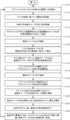
- FIG. 6 is a flowchart from the detection of the through hole TH by the rough alignment camera RA to the end of exposure.
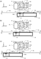
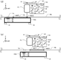
- 7 and 8 are conceptual side views showing main operations from the detection of the through hole TH to the end of exposure.
- step S111 the strip-shaped substrate FB is transferred in the X-axis direction by the supply roller FR and the take-up roller WR (see FIG. 1) while the strip-shaped substrate FB and the substrate stage FBS are separated from each other in the Z-axis direction. .
- the through-hole TH of the belt-like substrate FB that has been transferred temporarily stops below the rough alignment camera RA. Then, the rough alignment camera RA detects the through hole TH of the belt-like substrate FB.
- step S112 based on the detection result of the through hole TH of the rough alignment camera RA, the supply roller FR and the take-up roller WR transfer the belt-like substrate FB.
- the substrate stage FBS provided with the reference member 95 is disposed at the initial position.
- the through hole TH is positioned above the substrate side AIS mark 93 of the reference member 95.
- step S113 the substrate stage FBS stopped at a predetermined position is raised by the height adjustment unit 26, and the belt-like substrate FB and the substrate stage FBS come into contact with each other. Then, the vacuum suction hole 21 of the substrate stage FBS sucks the strip-shaped substrate FB.
- steps S114 to S117 the positional relationship between the mask side AIS mark 91 provided on the mask M as the pattern member and the substrate side AIS mark 93 of the substrate stage FBS, that is, the relative position between the mask M and the alignment camera AC. Measure baseline amount.
- step S114 the substrate stage FBS that has adsorbed the belt-like substrate FB moves the substrate-side AIS mark 93 to just below the alignment camera AC.
- the supply roller FR and the take-up roller WR rotate in accordance with the movement of the substrate stage FBS.
- the alignment camera AC detects the substrate-side AIS mark 93 through the through hole TH.
- the positions of the substrate stage FBS in the X-axis direction and the Y-axis direction are measured by the laser interferometer MM. Thereby, information regarding the relative position between the alignment camera AC and the substrate-side AIS mark 93 can be obtained.
- FIG. 7A shows a state where the alignment camera AC detects the substrate side AIS mark 93 through the through hole TH.
- step S115 the substrate stage FBS that has adsorbed the belt-like substrate FB is moved so that the substrate-side AIS mark 93 is located just below the projection optical system PL.
- the supply roller FR and the take-up roller WR rotate in accordance with the movement of the substrate stage FBS.
- the AIS image sensor 99 detects the mask side AIS mark 91 of the mask M and the substrate side AIS mark 93 on the substrate stage FBS by a so-called through-the-lens (TTL) method. More specifically, the illumination light that has passed through the mask side AIS mark 91 passes through the projection optical system PL and passes through the through hole TH to illuminate the substrate side AIS mark 93.
- TTL through-the-lens
- the AIS image sensor 99 captures an image of the mask side AIS mark 91 and an image of the substrate side AIS mark 93 through the lens system 97. At this time, the positions of the mask stage MST and the substrate stage FBS in the X-axis direction and the Y-axis direction are measured by the laser interferometer LM and the laser interferometer MM. Thereby, information on the relative position between the mask M, which is a pattern member, and the substrate-side AIS mark 93 can be obtained.
- FIG. 7B shows a state in which the AIS image sensor 99 detects the mask side AIS mark 91 and the substrate side AIS mark 93 through the through hole TH.
- step S117 with respect to the four alignment cameras AC, the relative positional relationship between the position of the mask M and the position of the alignment camera AC, that is, the baseline amount can be calculated based on the detection results of steps S114 and S116.
- the measurement of the baseline amount from step S114 to step S117 may be performed every time the exposure process is started, or is performed every predetermined number of lots or when replacing the belt-like substrate FB wound in a roll. You may do it.
- step S118 the four alignment cameras AC described above detect the alignment mark AM (F).
- a plurality of alignment marks AM AM (F), AM (B), AM (S)
- AM (F) are formed around the exposure area EA.
- the alignment mark AM (F) on the head side of the exposure area EA to be exposed next is detected.
- FIG. 7B shows a state in which the alignment mark AM (F) on the head side is detected by the alignment camera AC.
- the alignment camera AC can detect the alignment mark AM in a state where the AIS image sensor 99 detects the substrate-side AIS mark 93 through the through hole TH.
- step S119 the substrate stage FBS that has adsorbed the belt-like substrate FB is moved so that the four alignment cameras AC are at the position of the rear alignment mark AM (B) shown in FIG. At this time, the supply roller FR and the take-up roller WR rotate in accordance with the movement of the substrate stage FBS.
- step S120 the four alignment cameras AC detect the rear alignment mark AM (B).
- a plurality of alignment marks AM are formed around the exposure area EA.
- the alignment mark AM (B) on the tail side of the exposure area EA to be exposed next is detected.
- FIG. 7C shows a state in which the alignment mark AM (B) on the rear side is detected by the alignment camera AC.
- the alignment mark AM (S) on the side of the exposure area EA may be detected by the two alignment cameras AC from step S118 to step S120. By detecting all the alignment marks AM (AM (F), AM (B), AM (S)), it is calculated how the exposure area EA of the strip-shaped substrate FB is expanded and contracted.
- step S121 the projection image of the pattern of the mask M by the projection optical system PL is exposed based on the measurement result of the baseline amount obtained in step S117 and the detection result of the alignment mark AM obtained in steps S118 and S120.
- the substrate stage FBS is moved so as to come to one end of the area EA.
- the substrate stage FBS moves not only in the X-axis direction but also in the Y-axis direction and the ⁇ Z direction.
- the supply roller FR and the take-up roller WR rotate in accordance with the movement of the substrate stage FBS.
- FIG. 8D shows a state in which the projection image by the projection optical system PL has reached one end of the exposure area EA.
- step S122 the mask M and the substrate stage FBS scan synchronously, and exposure is performed by irradiating the exposure light EL.
- the supply roller FR and the take-up roller WR also rotate in synchronization with the movement of the substrate stage FBS.
- step S123 after the exposure of the exposure area EA is completed, the vacuum suction of the strip-shaped substrate FB is released. Then, the substrate stage FBS is lowered by the height adjusting unit 26.
- FIG. 8E shows a state where the exposure area EA has been exposed and the substrate stage FBS has been lowered.
- step S124 the supply roller FR and the take-up roller WR move the band-shaped substrate FB so that the through hole TH of the band-shaped substrate FB is transferred to the lower side of the rough alignment camera RA. Further, the substrate stage FBS moves to the initial position.
- the alignment camera AC detected the leading alignment mark AM (F), the lateral alignment mark AM (S), the trailing alignment mark AM (B), and the like. However, the alignment camera AC detects only the leading alignment mark AM (F), detects only the leading alignment mark AM (F) and the lateral alignment mark AM (S), and the exposure area EA. The operation may be appropriately changed according to the overlay accuracy.
- Second Example> shows an example in which the rough alignment cameras RA are arranged in one row in the X-axis direction and the alignment cameras AC are arranged in two rows in the X-axis direction.
- Alignment camera AC1 and alignment camera AC2 arranged in two rows in the X-axis direction shown in FIG. 10 or FIG. 11 respectively detect leading alignment mark AM (F) and trailing alignment mark AM (B).
- the alignment camera AC1 and the alignment camera AC2 have the same configuration, and are separated from the leading alignment mark AM (F) to the trailing alignment mark AM (B) in the X-axis direction.
- FIG. 9 is a flowchart from the detection of the through hole TH by the rough alignment camera RA to the end of exposure.
- 10 and 11 are conceptual side views illustrating main operations from detection of the through hole TH to the end of exposure.
- step S311 the strip-shaped substrate FB is transferred in the X-axis direction by the supply roller FR and the take-up roller WR (see FIG. 1) while the strip-shaped substrate FB and the substrate stage FBS are separated from each other in the Z-axis direction. .
- the through-hole TH of the belt-like substrate FB that has been transferred temporarily stops below the rough alignment camera RA. Then, the rough alignment camera RA detects the through hole TH of the belt-like substrate FB.
- step S312 based on the detection result of the through hole TH of the rough alignment camera RA, the supply roller FR and the take-up roller WR transfer the belt-like substrate FB.
- the substrate stage FBS provided with the reference member 95 is disposed at the initial position.
- the through hole TH is positioned above the substrate side AIS mark 93 of the reference member 95.
- step S313 the substrate stage FBS stopped at a predetermined position is raised by the height adjusting unit 26, and the belt-like substrate FB and the substrate stage FBS come into contact with each other. Then, the vacuum suction hole 21 of the substrate stage FBS sucks the strip-shaped substrate FB.
- steps S314 to S319 the relative positional relationship between the position of the mask M and the positions of the alignment camera AC1 and alignment camera AC2, that is, the baseline amount that is the relative position between the mask M and the alignment camera AC1 and alignment camera AC2 is measured.
- step S314 the substrate stage FBS that has adsorbed the belt-like substrate FB moves the substrate-side AIS mark 93 to a position directly below the alignment camera AC2.
- the alignment camera AC2 detects the substrate-side AIS mark 93 through the through hole TH.
- the positions of the substrate stage FBS in the X-axis direction and the Y-axis direction are measured by the laser interferometer MM. Thereby, information regarding the relative position between the alignment camera AC and the substrate-side AIS mark 93 can be obtained.
- FIG. 10A shows a state in which the alignment camera AC2 detects the substrate side AIS mark 93 through the through hole TH.
- step S315 the substrate stage FBS that has adsorbed the band-shaped substrate FB is moved so that the substrate-side AIS mark 93 is located just below the alignment camera AC1.
- step S316 the substrate stage FBS that has adsorbed the band-shaped substrate FB moves the substrate-side AIS mark 93 to a position directly below the alignment camera AC1.
- the alignment camera AC1 detects the substrate-side AIS mark 93 through the through hole TH.
- FIG. 10B shows a state in which the alignment camera AC1 detects the substrate side AIS mark 93 through the through hole TH.
- step S317 the substrate stage FBS that has adsorbed the belt-like substrate FB is moved so that the substrate-side AIS mark 93 is located just below the projection optical system PL.
- step S318 the mask-side AIS mark 91 of the mask M and the substrate-side AIS mark 93 on the substrate stage FBS are detected by the AIS image sensor 99 by a so-called through-the-lens (TTL) method. Based on the detection result, the relative position between the mask M and the substrate stage FBS is obtained. At this time, the positions of the mask stage MST and the substrate stage FBS in the X-axis direction and the Y-axis direction are measured by the laser interferometer LM and the laser interferometer MM.
- TTL through-the-lens
- FIG. 10C shows a state in which the AIS image sensor 99 detects the mask side AIS mark 91 and the substrate side AIS mark 93 through the through hole TH.
- step S319 for the alignment cameras AC1 and AC2, the relative positional relationship between the position of the mask M and the positions of the alignment cameras AC1 and AC2, that is, the baseline amount, can be calculated based on the detection results in steps S314 and S318. .
- the measurement of the baseline amount from step S314 to S319 may be performed every time the exposure process is started, or at the time of replacement of a predetermined number of lots or a belt-like substrate FB wound in a roll. You may do it.
- step S320 the alignment camera AC1 and the alignment camera AC2 described above simultaneously detect the leading alignment mark AM (F) and the trailing alignment mark AM (B) formed on the belt-like substrate FB.
- FIG. 10C shows a state in which the alignment mark AM (F) on the head side is detected by the alignment camera AC1, and the alignment mark AM (B) on the rear side is detected by the alignment camera AC2.
- the alignment cameras AC1 and AC2 detect the alignment marks AM (F) and AM (B) in a state where the AIS image sensor 99 detects the substrate-side AIS mark 93 through the through hole TH. it can.
- the alignment mark AM (S) on the side of the exposure area EA may also be detected by the alignment camera AC1 or AC2 through step S320. By detecting all the alignment marks AM (AM (F), AM (B), AM (S)), it is calculated how the exposure area EA of the strip-shaped substrate FB is expanded and contracted.
- step S321 based on the measurement result of the baseline amount obtained in step S319 and the detection results of the alignment marks AM (F) and AM (B) obtained in step S320, the mask M is projected by the projection optical system PL.
- the substrate stage FBS is moved so that the projected image of the pattern comes to one end of the exposure area EA. At this time, the substrate stage FBS moves not only in the X-axis direction but also in the Y-axis direction and the ⁇ Z direction.
- FIG. 11D shows a state in which the projection image by the projection optical system PL has reached one end of the exposure area EA.
- step S322 the mask M and the substrate stage FBS scan synchronously, and exposure is performed by irradiating the exposure light EL.
- the supply roller FR and the take-up roller WR also rotate in synchronization with the movement of the substrate stage FBS.
- step S323 after the exposure of the exposure area EA is completed, the vacuum suction of the belt-like substrate FB is released. Then, the substrate stage FBS is lowered by the height adjusting unit 26.
- FIG. 11E shows a state where the exposure area EA has been exposed and the substrate stage FBS has been lowered.
- step S324 the supply roller FR and the take-up roller WR move the band-shaped substrate FB so that the through hole TH of the band-shaped substrate FB is transferred to the lower side of the rough alignment camera RA. Further, the substrate stage FBS moves to the initial position.
- the mask M drawn on the quartz glass is used as the pattern member.
- a DMD Direct Micro Mirror Device
- the alignment method of this embodiment can be applied.
- Substrate FBS ... Substrate stage FR ... Supply roller LM, LMx ... Laser interferometer M ... Mask MST ... Mask stage MM, MMx ... Laser interferometer PI ... Projection image PL ... Projection Optical system RA ... rough alignment turtle La RCC... Image sensor TH for low magnification... Through hole WR... Winding roller
Landscapes
- General Physics & Mathematics (AREA)
- Physics & Mathematics (AREA)
- Engineering & Computer Science (AREA)
- Epidemiology (AREA)
- Health & Medical Sciences (AREA)
- Environmental & Geological Engineering (AREA)
- Multimedia (AREA)
- Public Health (AREA)
- Life Sciences & Earth Sciences (AREA)
- Sustainable Development (AREA)
- Exposure And Positioning Against Photoresist Photosensitive Materials (AREA)
- Liquid Crystal (AREA)
- Container, Conveyance, Adherence, Positioning, Of Wafer (AREA)
Abstract
【課題】 帯状の基板と、この基板に露光されるパターンが設けられたパターン部材との位置合わせを高精度に行うことができるアライメント方法を提供する。 【解決手段】 帯状の基板(FB)と、該基板(FB)に露光されるパターンが設けられたパターン部材との位置合わせを行うアライメント方法である。このアライメント方法は、基板(FB)を保持して移動するステージ装置に設けられた基準部材(95)とパターン部材との相対位置に関する第1情報を基板(FB)に設けられた貫通孔(TH)を介して検出する工程と、基板(FB)に設けられたアライメントマーク(AM)の位置に関する第2情報を検出する工程と、アライメントマーク(AM)の位置を検出する検出器と基準部材(95)との相対位置に関する第3情報を貫通孔(TH)を介して検出する工程と、第1、第2及び第3情報に基づいてステージ装置を駆動する工程と、を備える。
Description
本発明は、帯状の基板と、該基板に露光されるパターンが設けられたパターン部材との位置合わせを行うアライメント技術、そのアライメント技術を使った露光技術に関する。
LCD、PDP又は有機エレクトロルミネッセンスといったフラットパネルディスプレイ(FPD)に用いられるガラス基板又は樹脂基板は、画面の大型化の要望に応じてサイズが大型化する傾向にある。マスクの回路パターンをガラス基板又は樹脂基板に露光する露光装置は、ガラス基板又は樹脂基板の大型化に応じて大型化している。
また露光装置の中には、FPDなどの量産と大型化に対応するために、ロール状に巻かれた帯状の基板を移送させて露光する装置も出現している。例えば特許文献1で開示される投影露光装置は、帯状の基板を真空及び真空解除を交互に行うとともにステージが移送方向に移動することで、帯状の基板を間欠的に移送している。一旦ステージの移動方向とマスクの投影パターンの方向とを一致させると、投影露光装置はステージを高精度に順次動かして帯状の基板を露光領域に移送し、マスクのパターンを帯状の基板に順次投影露光させている。
また、特許文献2は大型のガラス基板を露光する露光装置を開示する。この露光装置は基準部材を使ってマスクとオフアクシス方式のアライメント検出系との相対位置であるベースライン量を求める技術を開示している。ベースライン量の計測後、アライメント検出系はガラス基板に形成されたアライメントマークを検出している。
また、特許文献2は大型のガラス基板を露光する露光装置を開示する。この露光装置は基準部材を使ってマスクとオフアクシス方式のアライメント検出系との相対位置であるベースライン量を求める技術を開示している。ベースライン量の計測後、アライメント検出系はガラス基板に形成されたアライメントマークを検出している。
しかし、特許文献1に開示される投影露光装置は、ロール状に巻かれた帯状の基板の移送中に、帯状の基板の位置を観察するアライメントカメラなどについて開示していない。仮に、特許文献2に開示されているベースライン計測及びアライメントマークの検出に関する技術を特許文献1に適用した場合には、移送方向に帯状の基板が連続して存在するため、基準部材を検出するには帯状の基板を介して検出を行わなければならない。しかしながら、帯状の基板を介してマーク検出を行うと、基板の歪み又は厚さの不均一性等の影響を受けることとなり、高精度にマーク検出を行うことができないという問題がある。
本発明の態様は、帯状の基板と、この基板に露光されるパターンが設けられたパターン部材との位置合わせを高精度に行うことができるアライメント方法、アライメント装置、露光方法、露光装置及びデバイス製造方法を提供することを目的とする。
本発明の第1の態様によれば、帯状の基板と、該基板に露光されるパターンが設けられたパターン部材との位置合わせを行うアライメント方法において、基板を保持して移動するステージ装置に設けられた基準部材とパターン部材との相対位置に関する第1情報を基板に設けられた貫通孔を介して検出する工程と、基板に設けられたアライメントマークの位置に関する第2情報を検出する工程と、アライメントマークの位置を検出する検出器と基準部材との相対位置に関する第3情報を貫通孔を介して検出する工程と、第1、第2及び第3情報に基づいてステージ装置を駆動する工程と、を備えるアライメント方法が提供される。
本発明の第2の態様によれば、パターン部材に設けられたパターンを帯状の基板に露光する露光方法において、本発明の第1の態様のアライメント方法を用いて基板とパターン部材との位置合せを行う工程と、パターン部材に対して位置合わせが行われた基板に、パターンを介して露光光を照射する工程と、を備える露光方法が提供される。
本発明の第3の態様によれば、本発明の第2の態様の露光方法を用いて、感光剤が塗布された基板にパターンを転写する工程と、パターンが転写された基板の感光剤を現像してパターンに対応する凹凸形状を有した転写パーン層を形成する工程と、転写パターン層を介して基板を加工する工程と、を備えるデバイス製造方法が提供される。
本発明の第4の態様によれば、帯状の基板と、該基板に露光されるパターンが設けられたパターン部材との位置合わせを行うアライメント装置において、帯状の基板を保持して移動するステージ装置と、ステージ装置に配置された基準部材と、基板に設けられた貫通孔を介して基準部材とパターン部材との相対位置に関する第1情報を検出する第1検出器と、基板に設けられたアライメントマークの位置に関する第2情報を検出する第2検出器と、貫通孔を介して第2検出器と基準部材との相対位置に関する第3情報を検出する第3検出器と、第1、第2及び第3情報に基づいて、ステージ装置を駆動する駆動機構と、
を備えるアライメント装置が提供される。
を備えるアライメント装置が提供される。
本発明の第5の態様によれば、パターン部材に設けられたパターンを帯状の基板に露光する露光装置において、基板とパターン部材との位置合せを行う本発明の第4の態様のアライメント装置と、パターン部材に対して位置合わせが行われた基板に、パターンを介して露光光を照射する照射装置と、を備える露光装置が提供される。
本発明の態様によれば、帯状の基板と、この基板に露光されるパターンが設けられたパターン部材との位置合わせを高精度に行うことができる。
<露光装置の全体構成>
以下、本発明の実施形態の露光装置EXについて図1を参照しながら説明する。図1(a)は本実施形態の露光装置EXを示す概略平面図であり、理解を助けるため帯状の基板FBより下側の部分が描かれている。図1(b)は露光装置EXの概略側面図である。
以下、本発明の実施形態の露光装置EXについて図1を参照しながら説明する。図1(a)は本実施形態の露光装置EXを示す概略平面図であり、理解を助けるため帯状の基板FBより下側の部分が描かれている。図1(b)は露光装置EXの概略側面図である。
露光装置EXは、帯状の基板FBを供給する供給ローラFRと帯状の基板FBを巻き取る巻き取りローラWRとを有する。供給ローラFR及び巻き取りローラWRは帯状の基板FBを矢印方向に移送することができる。ここで帯状の基板FBはロール状に巻き取ることができる薄い樹脂フィルムである。帯状の基板FBはその面積に対して厚さが十分に薄い基板であり可撓性を有する。帯状の基板FBは例えばX軸方向に100メートルの長さであり、Y軸方向に1メールルの幅であり、厚さが100ミクロンメートルである。この帯状の基板FBのマスクM側の片面にフォトレジストが塗布されている。帯状の基板FBは、具体的には、ポリエチレン樹脂、ポリプロピレン樹脂、ポリエステル樹脂、エチレンビニル共重合体樹脂、ポリ塩化ビニル樹脂、セルロース樹脂、ポリアミド樹脂、ポリイミド樹脂、ポリカーボネート樹脂、ポリスチレン樹脂、酢酸ビニル樹脂を使うことができる。
露光装置EXは、パターンが形成されたマスクMを支持するマスクステージMSTと、帯状の基板FBを支持する基板ステージFBSとを備えている。マスクMは石英ガラスに回路パターンなどが描画された部材である。露光装置EXは、マスクMを支持するマスクステージMSTのX軸方向及びY軸方向における位置を検出する複数のレーザ干渉計LMと、帯状の基板FBを支持する基板ステージFBSのX軸方向及びY軸方向における位置を検出する複数のレーザ干渉計MMとを備えている。マスクステージMSTは、不図示のリニアモータなどによってX軸方向に長いストロークを移動可能でありY軸方向に短いストロークを移動可能である。基板ステージFBSも同様にX軸方向に長いストロークを移動可能でありY軸方向に短いストローク移動可能である。なお、図1(b)ではX軸方向の位置を検出するレーザ干渉計LMx及びレーザ干渉計MMxを1つずつしか描いていない。
また露光装置EXは、不図示の照明光学系による露光光ELで照明されたマスクMのパターンの像を基板ステージFBSに支持されている帯状の基板FBに投影する投影光学系PLを有している。図1(a)にマスクMのパターンの投影像PIが台形状に示されているように、露光装置EXはX軸方向に2列に配置されてY軸方向に交互に並んだ3つの投影光学系PLを有している。図1(b)ではその1つの投影光学系PLが示されている。マスクステージMSTに支持されているマスクMと基板ステージFBSに支持されている帯状の基板FBとは、投影光学系PLを介して共役な位置関係に配置される。
図1(b)に示されているように、露光装置EXは帯状の基板FBに所定の貫通孔THを形成する穿孔器10が設けられている。穿孔器10は供給ローラFR側に配置されている。穿孔器10は型を押し当てて帯状の基板FBに貫通孔THを形成するものであってもよく、レーザ光などで帯状の基板FBに貫通孔THを形成するものであってもよい。本実施形態の穿孔器10はY軸方向に例えば4つの貫通孔THを開ける。貫通孔THの直径は後述する基板側AISマーク93などよりも大きな直径であればよい。なお、供給ローラFRに帯状の基板FBを取り付ける際にすでに貫通孔THが開けられている場合には、穿孔器10を設ける必要はない。なお、穿孔器10が開ける4つの貫通孔THは投影光学系PLのY軸方向の両端の位置と、隣り合う投影光学系PLの台形形状の投影像PIが互いに重なる位置とに形成される。
露光装置EXは投影光学系PLに隣接して帯状の基板FBに設けられているアライメントマークAMを検出するアライメントカメラACを4つ有している。またアライメントカメラACに隣接して帯状の基板FBに設けられている貫通孔THを検出する2つのラフアライメントカメラRAを有している。アライメントマークAMは、帯状の基板FBにおいて露光光ELの照射領域である露光領域EAの周辺にすでに複数形成されている。本実施形態において、1つの露光領域EAの周辺ごとに全部で16個のアライメントマークAMが形成されている。なお、図ではアライメントマークは「+」として示されているが、例えばボックスマーク「□」でもよい。
本実施形態におけるアライメントカメラACはオフアクシス方式であり、アライメント処理を行うに際し、マスクMとアライメントカメラACとの相対位置であるベースライン量が計測される。なお、図1(b)ではアライメントカメラAC及びラフアライメントカメラRAを1つずつしか描いていない。
図1(b)に示されるように、マスクMにはベースライン計測用のマスク側AISマーク91が設けられており、基板ステージFBSにはベースライン計測用の基板側AISマーク93を有する基準部材95が設けられている。また、マスク側AISマーク91は、マスクMの特定位置(例えば中心位置)に対して所定の位置関係で設けられている。図1(a)に示されるように、マスク側AISマーク91と基板側AISマーク93とは対応しており、それぞれY軸方向に例えば4つ並んで設けられている。
ここで、本実施形態に係る露光装置EXは、露光光ELに対してマスクMと帯状の基板FBとを同期移動して走査露光する走査型露光装置であり、以下の説明において、投影光学系PLの光軸方向をZ軸方向、Z軸方向に垂直な方向でマスクM及び帯状の基板FBの同期移動方向をX軸方向(走査方向)、Z軸方向及びX軸方向(走査方向)と直交する方向をY軸方向(非走査方向)とする。
図2は、図1(b)のBで示された範囲を拡大した概念側面図である。
<基板ステージの構成>
帯状の基板FBを支持する基板ステージFBSは真空吸着孔21を有しており、真空吸着孔21を介して帯状の基板FBを保持する。真空吸着孔21は不図示の真空ポンプなどに接続されている。基板ステージFBSは、X軸方向の一次元の走査露光を行うべくX軸方向に長いストロークと、走査方向と直交するY軸方向に位置合わせするための短いストロークとを移動できるように、この基板ステージFBSの下側にX軸方向、Y軸方向及びZ軸方向の中心としたθZ方向(回転方向)に移動させる基板ステージ移動部28を備えている。基板ステージ移動部28は不図示の制御装置により制御される。基板ステージFBSがX軸方向に大きく移動した状態を点線で示している。
基板ステージ移動部28の上部には、3点又は4点の高さ調整部26が載置されている。高さ調整部26はZ軸方向に約10mmのストロークを有している。例えば露光装置EXが露光領域EAを走査露光した後、帯状の基板FBのみが移送され次の露光領域EAが基板ステージFBSの上に移動するまで、帯状の基板FBと基板ステージFBSとを数mmの間隙を空けることが好ましい。そのため高さ調整部26は帯状の基板FBと基板ステージFBSとの間隙を形成するためのストロークを有している。また、高さ調整部26は、投影光学系PLの結像面と基板ステージFBSに吸着された帯状の基板FBの表面とを一致させるため、基板ステージFBSを光軸方向(Z軸方向)に移動させる。また、3点又は4点の高さ調整部26のうちの1点又は2点を移動させて、X軸方向を中心としたθX方向(回転方向)、及びY軸方向を中心としたθY方向(回転方向)に基板ステージFBSを移動させることも可能となっている。また、基板ステージFBSをZ軸方向に高さ調整する替わりに基板FBをZ軸方向に高さ調整してもよい。この場合、例えば供給ローラFR及び巻き取りローラWRをZ軸方向に移動させる機構を備えるとよい。
図2に示すように、基板ステージFBSの表面と同一面に基準部材95が取り付けられている。基準部材95の下方には、基準部材95を通過した光を集光するレンズ系97と、レンズ系97を介した通過光を受光するAIS撮像素子99とが埋設されている。AIS撮像素子99はMOS又はCCDなど二次元画像素子である。
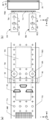
図3は、帯状の基板FBを支持する基板ステージFBSの別の実施例を示した概念図である。図3(a)は本実施形態の基板ステージFBSを示す概略平面図であり、理解を助けるため帯状の基板FBより下側の部分が描かれている。図3(b)は露光装置EXの概略側面図である。
図2では帯状の基板FBを支持する基板ステージFBSは真空吸着孔21を備えていたが、必ずしも真空吸着孔21を備える必要はない。例えば図3に示されるように、露光領域EAをX軸方向に挟むように一対の圧着固定部30を設けても良い。圧着固定部30は2対のピストン部33と1対の圧着板35とからなる。2対のピストン部33は基板ステージFBSの四隅付近に配置され、その1対のピストン部33に1枚のY軸方向に伸びる圧着板35が配置されている。一対の圧着板35は、その間に少なくとも露光領域EA及び貫通孔THが入るように配置されている。
図3(b)に描かれた状態から2対のピストン部33がZ軸方向に下がると、一対の圧着板35は帯状の基板FBを基板ステージFBSの表面に圧着させる。帯状の基板FBが長いために、余分な張力が帯状の基板FBに加わる場合がある。また、供給ローラFR及び巻き取りローラWRが基板ステージFBSの移動と同期しない場合が生じるおそれもある。これらの場合であっても、帯状の基板FBがZ軸方向に圧着板35で基板ステージFBSに押し付けられているため、帯状の基板FBの位置がずれるおそれがない。
なお、基板ステージFBSに設けられた真空吸着孔21に加えて、圧着固定部30を設けても良い。このような構成にすれば、帯状の基板FBの位置ずれがより少なくなる。
なお、基板ステージFBSに設けられた真空吸着孔21に加えて、圧着固定部30を設けても良い。このような構成にすれば、帯状の基板FBの位置ずれがより少なくなる。
<アライメントカメラの構成>
再び図2に戻り、アライメントカメラACについて説明する。アライメントカメラACは、帯状の基板FBに設けられているアライメントマークAMを検出する。アライメントカメラACは、交互に並んだ投影光学系PLの間で帯状の基板FBに対向するようにY軸方向に4つ並んで設けられている。
再び図2に戻り、アライメントカメラACについて説明する。アライメントカメラACは、帯状の基板FBに設けられているアライメントマークAMを検出する。アライメントカメラACは、交互に並んだ投影光学系PLの間で帯状の基板FBに対向するようにY軸方向に4つ並んで設けられている。
アライメントカメラACは、アライメント用検出光を射出するアライメント用光源81と、アライメント用光源81から射出した検出光を引き伸ばすリレーレンズ82と、リレーレンズ82の光路下流側に設けられたハーフミラー83と、を有する。またアライメントカメラACは、ハーフミラー83を通過した検出光を帯状の基板FB上に照射する対物レンズ84を有している。また、アライメントカメラACは、帯状の基板FBからの反射光を分岐するビームスプリッタ85と倍率の高い高倍用レンズ86と、高倍用撮像素子ACCとを有しており、貫通孔TH内の狭い領域を高精度で計測可能である。高倍用撮像素子ACCはMOS又はCCDなど二次元画像素子である。すなわち、アライメントカメラACは、検出光の照射によりハーフミラー83及び対物レンズ84を介して帯状の基板FB上のアライメントマークAMを照射し、そのアライメントマークAMからの反射光をハーフミラー83、ビームスプリッタ85及び高倍用レンズ86を介して高倍用撮像素子ACCで撮像する。
<ラフアライメントカメラの構成>
次にラフアライメントカメラRAについて説明する。ラフアライメントカメラRAは、帯状の基板FBに設けられている4つの貫通孔THの位置を検出する。このラフアライメントカメラRAはアライメントカメラACが貫通孔THを介して基板側AISマーク93を検出するために設けられている。ラフアライメントカメラRAはアライメントカメラACと同じように、交互に並んだ投影光学系PLの間で帯状の基板FBに対向するようにY軸方向に2つ又は4つ並んで設けられている。
次にラフアライメントカメラRAについて説明する。ラフアライメントカメラRAは、帯状の基板FBに設けられている4つの貫通孔THの位置を検出する。このラフアライメントカメラRAはアライメントカメラACが貫通孔THを介して基板側AISマーク93を検出するために設けられている。ラフアライメントカメラRAはアライメントカメラACと同じように、交互に並んだ投影光学系PLの間で帯状の基板FBに対向するようにY軸方向に2つ又は4つ並んで設けられている。
ラフアライメントカメラRAは、アライメントカメラACの光源を共用するため、アライメント用光源81から対物レンズ84までの構成はアライメントカメラACと同じである。ラフアライメントカメラRAは、帯状の基板FBからの反射光を反射する反射ミラー87と倍率の低い低倍用レンズ88と、低倍用撮像素子RCCとを有しており、帯状の基板FBの広い領域を計測可能である。低倍用撮像素子RCCもMOS又はCCDなど二次元画像素子である。すなわち、ラフアライメントカメラRAは、検出光の照射によりハーフミラー83及び対物レンズ84を介して帯状の基板FB上の貫通孔TH及びその周辺を照射する。そしてその貫通孔THの周辺からの反射光をハーフミラー83及び低倍用レンズ88などを介して低倍用撮像素子RCCで撮像する。
<ラフアライメントカメラによる貫通孔の検出>
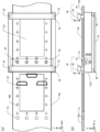
図4はラフアライメントカメラRAによる貫通孔THを検出する状態を示した概念図である。図4(a)はその平面概念図であり、図4(b)はX軸方向から見た概略側面図である。
なお、本実施形態では、ラフアライメントカメラRAは、帯状の基板FBの両端側の2つの貫通孔THを検出するようにY軸方向に2つ並べて配置されている。4つの貫通孔THはほぼX軸方向に同じ位置に形成されているため、4つの貫通孔THに対してラフアライメントカメラRAを4つ用意する必要はなく、1つ用意するだけでもよい。
図4はラフアライメントカメラRAによる貫通孔THを検出する状態を示した概念図である。図4(a)はその平面概念図であり、図4(b)はX軸方向から見た概略側面図である。
なお、本実施形態では、ラフアライメントカメラRAは、帯状の基板FBの両端側の2つの貫通孔THを検出するようにY軸方向に2つ並べて配置されている。4つの貫通孔THはほぼX軸方向に同じ位置に形成されているため、4つの貫通孔THに対してラフアライメントカメラRAを4つ用意する必要はなく、1つ用意するだけでもよい。
図4(b)に示されるように、帯状の基板FBと基板ステージFBSとがZ軸方向に所定の距離だけ離れた状態で、供給ローラFR及び巻き取りローラWR(図1参照)によって帯状の基板FBがX軸方向に移送されてくる。供給ローラFR及び巻き取りローラWRは、穿孔器10によって形成された貫通孔THがラフアライメントカメラRAの真下に来る位置で帯状の基板FBの移送を停止する。
図4(a)は貫通孔THがラフアライメントカメラRAの真下に来た状態を示している。この状態で、ラフアライメントカメラRAは検出光を照射する。そしてラフアライメントカメラRAは貫通孔THの周辺からの反射光を対物レンズ84及び低倍用レンズ88などを介して低倍用撮像素子RCCで撮像する。
ラフアライメントカメラRAは低倍用撮像素子RCCで撮像された画像に基づいて、貫通孔THとその周辺とのエッジ情報から貫通孔THの座標値を求める。なお、貫通孔THの座標値を求める方法として画像処理により貫通孔THの中心位置を求めたり記憶されたテンプレート情報とのパターンマッチング法で求めたりしてもよい。不図示の制御装置は、求められた貫通孔THの座標値を用いて補正パラメータを求める。そして制御装置は、貫通孔THの中心が基準部材95の基板側AISマーク93の位置に合致するように、供給ローラFR及び巻き取りローラWR(図1参照)に補正パラメータを与える。
<アライメントカメラによる基板側AISマークの検出>
図5はアライメントカメラACによる基板側AISマーク93を検出する状態を示した概念図である。図5(a)はその平面概念図であり、図5(b)はX軸方向から見た概略側面図である。
図5はアライメントカメラACによる基板側AISマーク93を検出する状態を示した概念図である。図5(a)はその平面概念図であり、図5(b)はX軸方向から見た概略側面図である。
上述したようにラフアライメントカメラRAによって貫通孔THの座標値が求められ、供給ローラFR及び巻き取りローラWRに制御装置から補正パラメータが与えられる。このため、貫通孔THが基板側AISマーク93の位置に合致する位置まで帯状の基板FBがX軸方向に移送される。基板側AISマーク93の上に貫通孔THがなくアライメントカメラACが基板側AISマーク93を検出できない状況を防ぐことができる。そして、図5(b)に示されるように、帯状の基板FBが基板ステージFBSに真空吸着された状態となる。
図5(a)は貫通孔THがアライメントカメラACの真下に来た状態を示している。この状態で、アライメントカメラACは検出光を照射する。そしてアライメントカメラACは基板側AISマーク93からの反射光を対物レンズ84及び高倍用レンズ86などを介して高倍用撮像素子ACCで撮像する。
アライメントカメラACは高倍用撮像素子ACCで撮像された画像に基づいて、基板側AISマーク93の座標値を求める。なお、基板側AISマーク93の座標値を求める方法として画像処理により基板側AISマーク93の中心位置を求めたり記憶されたテンプレート情報とのパターンマッチング法で求めたりしてもよい。また基板側AISマーク93を備える基板ステージFBSの位置は、レーザ干渉計MM(図1参照)で測定されている。このため、不図示の制御装置は、求められた基板側AISマーク93の座標値及びレーザ干渉計MMの測定値を用いてアライメントカメラACの位置を基準として基板側AISマーク93の位置を求める。
<ベースライン計測から露光までの動作:第1例>
本実施形態において、アライメントマークAMを検出するに際し、マスクMとアライメントカメラACとの相対位置であるベースライン量が前もって計測される。
本実施形態において、アライメントマークAMを検出するに際し、マスクMとアライメントカメラACとの相対位置であるベースライン量が前もって計測される。
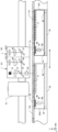
図6はラフアライメントカメラRAによる貫通孔THの検出から露光終了までのフローチャートである。図7及び図8は貫通孔THの検出から露光終了までの主要な動作を示した概念側面図である。
ステップS111において、帯状の基板FBと基板ステージFBSとがZ軸方向に離れた状態で、供給ローラFR及び巻き取りローラWR(図1参照)によって帯状の基板FBがX軸方向に移送されてくる。移送されてきた帯状の基板FBの貫通孔THは、一旦、ラフアライメントカメラRAの下側で停止する。そして、ラフアライメントカメラRAは帯状の基板FBの貫通孔THを検出する。
ステップS112では、ラフアライメントカメラRAの貫通孔THの検出結果に基づいて、供給ローラFR及び巻き取りローラWRが帯状の基板FBを移送させる。この際に基準部材95を設ける基板ステージFBSは初期位置に配置されている。これによって、貫通孔THが基準部材95の基板側AISマーク93の上方に位置決めされる。
ステップS113では、所定の位置で停止している基板ステージFBSが高さ調整部26によって上昇し、帯状の基板FBと基板ステージFBSとが接する。そして基板ステージFBSの真空吸着孔21が帯状の基板FBを吸着する。
ステップS113では、所定の位置で停止している基板ステージFBSが高さ調整部26によって上昇し、帯状の基板FBと基板ステージFBSとが接する。そして基板ステージFBSの真空吸着孔21が帯状の基板FBを吸着する。
ステップS114からS117において、パターン部材であるマスクMに設けられたマスク側AISマーク91と、基板ステージFBSの基板側AISマーク93との位置関係、すなわちマスクMとアライメントカメラACとの相対位置であるベースライン量を計測する。
ステップS114では、帯状の基板FBを吸着した基板ステージFBSが基板側AISマーク93をアライメントカメラACの真下まで移動する。このときに供給ローラFR及び巻き取りローラWRは基板ステージFBSの移動に合わせて回転する。この帯状の基板FBの移動によって、アライメントカメラACは貫通孔THを通して基板側AISマーク93を検出する。この際に基板ステージFBSのX軸方向及びY軸方方向の位置がレーザ干渉計MMによって計測される。これによりアライメントカメラACと基板側AISマーク93との相対位置に関する情報を得ることができる。図7(a)はアライメントカメラACが貫通孔THを通して基板側AISマーク93を検出する状態を示している。
ステップS115では、帯状の基板FBを吸着した基板ステージFBSが移動し、基板側AISマーク93が投影光学系PLの真下までくるようにする。このときに供給ローラFR及び巻き取りローラWRは基板ステージFBSの移動に合わせて回転する。
ステップS116では、いわゆるスルー・ザ・レンズ(TTL)方式により、マスクMのマスク側AISマーク91と基板ステージFBS上の基板側AISマーク93とをAIS撮像素子99で検出する。より具体的には、マスク側AISマーク91を通過した照明光は投影光学系PLを通過するとともに貫通孔THを通過して基板側AISマーク93を照明する。AIS撮像素子99は、マスク側AISマーク91の像と基板側AISマーク93の像とをレンズ系97を介して撮像する。この際にマスクステージMST及び基板ステージFBSのX軸方向及びY軸方方向の位置がレーザ干渉計LM及びレーザ干渉計MMによって計測される。これによりパターン部材であるマスクMと基板側AISマーク93との相対位置に関する情報を得ることができる。図7(b)はAIS撮像素子99が貫通孔THを通してマスク側AISマーク91及び基板側AISマーク93を検出する状態を示している。
ステップS116では、いわゆるスルー・ザ・レンズ(TTL)方式により、マスクMのマスク側AISマーク91と基板ステージFBS上の基板側AISマーク93とをAIS撮像素子99で検出する。より具体的には、マスク側AISマーク91を通過した照明光は投影光学系PLを通過するとともに貫通孔THを通過して基板側AISマーク93を照明する。AIS撮像素子99は、マスク側AISマーク91の像と基板側AISマーク93の像とをレンズ系97を介して撮像する。この際にマスクステージMST及び基板ステージFBSのX軸方向及びY軸方方向の位置がレーザ干渉計LM及びレーザ干渉計MMによって計測される。これによりパターン部材であるマスクMと基板側AISマーク93との相対位置に関する情報を得ることができる。図7(b)はAIS撮像素子99が貫通孔THを通してマスク側AISマーク91及び基板側AISマーク93を検出する状態を示している。
ステップS117では、4つのアライメントカメラACに関して、ステップS114及びS116の検出結果に基づいてマスクMの位置とアライメントカメラACの位置との相対位置関係、つまりベースライン量を算出することができる。
なお、ステップS114からS117までのベースライン量の計測は、露光処理開始毎に行ってもよいし、予め設定した所定ロット数毎または一つロール状に巻かれた帯状の基板FBの交換時に行うようにしてもよい。
なお、ステップS114からS117までのベースライン量の計測は、露光処理開始毎に行ってもよいし、予め設定した所定ロット数毎または一つロール状に巻かれた帯状の基板FBの交換時に行うようにしてもよい。
次にステップS118では、上述した4つのアライメントカメラACはアライメントマークAM(F)を検出する。図5に示されたように、露光領域EAの周辺に複数のアライメントマークAM(AM(F)、AM(B)、AM(S))が形成されている。このうち、次に露光する露光領域EAの先頭側のアライメントマークAM(F)を検出する。
この際にレーザ干渉計MMによって基板ステージFBSのX軸方向及びY軸方向の位置並びにZ軸方向の中心としたθZ方向の回転も検出される。図7(b)はアライメントカメラACにより先頭側のアライメントマークAM(F)を検出する状態を示している。なお、この図7(b)ではAIS撮像素子99が貫通孔THを通して基板側AISマーク93を検出する状態でアライメントカメラACがアライメントマークAMを検出することができる。
ステップS119では、帯状の基板FBを吸着した基板ステージFBSが移動し、4つのアライメントカメラACが図5に示された後尾側のアライメントマークAM(B)の位置にくるようにする。このときに供給ローラFR及び巻き取りローラWRは基板ステージFBSの移動に合わせて回転する。
ステップS120では、4つのアライメントカメラACは、後尾側のアライメントマークAM(B)を検出する。露光領域EAの周辺に複数のアライメントマークAMが形成されている。このうち、次に露光する露光領域EAの後尾側のアライメントマークAM(B)を検出する。図7(c)はアライメントカメラACにより後尾側のアライメントマークAM(B)を検出する状態を示している。
なお、露光領域EAの横側のアライメントマークAM(S)もステップS118からステップS120にかけて2つのアライメントカメラACが検出してもよい。すべてのアライメントマークAM(AM(F)、AM(B)、AM(S))を検出することで、帯状の基板FBの露光領域EAがどのように伸縮しているかが算出される。
ステップS121では、ステップS117で求められたベースライン量の計測の結果及びステップS118及びS120で求められたアライメントマークAMの検出結果に基づいて、投影光学系PLによるマスクMのパターンの投影像が露光領域EAの一端にくるように基板ステージFBSを移動させる。この際に基板ステージFBSは、X軸方向だけでなくY軸方向及びθZ方向にも移動する。また、このときに供給ローラFR及び巻き取りローラWRは基板ステージFBSの移動に合わせて回転する。図8(d)は投影光学系PLによる投影像が露光領域EAの一端に来た状態を示している。
ステップS122では、マスクMと基板ステージFBSとが同期走査し、露光光ELが照射されることで露光が行われる。このときに供給ローラFR及び巻き取りローラWRも基板ステージFBSの動きに同期して回転する。
ステップS123では、露光領域EAの露光が終了した後、帯状の基板FBの真空吸着が解除される。そして基板ステージFBSは高さ調整部26によって下降する。図8(e)は露光領域EAが露光終了し基板ステージFBSが下降した状態を示している。
ステップS124では、帯状の基板FBの貫通孔THがラフアライメントカメラRAの下側に移送されるように、供給ローラFR及び巻き取りローラWRが帯状の基板FBを移送させる。また基板ステージFBSは初期位置に移動する。
ステップS123では、露光領域EAの露光が終了した後、帯状の基板FBの真空吸着が解除される。そして基板ステージFBSは高さ調整部26によって下降する。図8(e)は露光領域EAが露光終了し基板ステージFBSが下降した状態を示している。
ステップS124では、帯状の基板FBの貫通孔THがラフアライメントカメラRAの下側に移送されるように、供給ローラFR及び巻き取りローラWRが帯状の基板FBを移送させる。また基板ステージFBSは初期位置に移動する。
なお、図6から図8の動作において、アライメントカメラACは先頭側のアライメントマークAM(F)、横側のアライメントマークAM(S)及び後尾側のアライメントマークAM(B)などを検出した。しかし、アライメントカメラACは先頭側のアライメントマークAM(F)のみを検出したり、先頭側のアライメントマークAM(F)及び横側のアライメントマークAM(S)のみを検出したりと、露光領域EAの重ね合わせ精度に合わせて適宜動作を変更してもよい。
<ベースライン計測から露光までの動作:第2例>
第1例とは異なり、第2例では、ラフアライメントカメラRAがX軸方向に一列、アライメントカメラACがX軸方向に2列配置された例を示す。先頭側のアライメントマークAM(F)と後尾側のアライメントマークAM(B)とを、図10又は図11に示されるX軸方向に2列配置されたアライメントカメラAC1及びアライメントカメラAC2がそれぞれ検出する。アライメントカメラAC1とアライメントカメラAC2とは構成は同じで、X軸方向に先頭側のアライメントマークAM(F)から後尾側のアライメントマークAM(B)まで離れている。
第1例とは異なり、第2例では、ラフアライメントカメラRAがX軸方向に一列、アライメントカメラACがX軸方向に2列配置された例を示す。先頭側のアライメントマークAM(F)と後尾側のアライメントマークAM(B)とを、図10又は図11に示されるX軸方向に2列配置されたアライメントカメラAC1及びアライメントカメラAC2がそれぞれ検出する。アライメントカメラAC1とアライメントカメラAC2とは構成は同じで、X軸方向に先頭側のアライメントマークAM(F)から後尾側のアライメントマークAM(B)まで離れている。
図9はラフアライメントカメラRAによる貫通孔THの検出から露光終了までのフローチャートである。図10及び図11は貫通孔THの検出から露光終了までの主要な動作を示した概念側面図である。
ステップS311において、帯状の基板FBと基板ステージFBSとがZ軸方向に離れた状態で、供給ローラFR及び巻き取りローラWR(図1参照)によって帯状の基板FBがX軸方向に移送されてくる。移送されてきた帯状の基板FBの貫通孔THは、一旦、ラフアライメントカメラRAの下側で停止する。そして、ラフアライメントカメラRAは帯状の基板FBの貫通孔THを検出する。
ステップS312では、ラフアライメントカメラRAの貫通孔THの検出結果に基づいて、供給ローラFR及び巻き取りローラWRが帯状の基板FBを移送させる。この際に基準部材95を設ける基板ステージFBSは初期位置に配置されている。これによって、貫通孔THが基準部材95の基板側AISマーク93の上方に位置決めされる。
ステップS313では、所定の位置で停止している基板ステージFBSが高さ調整部26によって上昇し、帯状の基板FBと基板ステージFBSとが接する。そして基板ステージFBSの真空吸着孔21が帯状の基板FBを吸着する。
ステップS313では、所定の位置で停止している基板ステージFBSが高さ調整部26によって上昇し、帯状の基板FBと基板ステージFBSとが接する。そして基板ステージFBSの真空吸着孔21が帯状の基板FBを吸着する。
ステップS314からS319において、マスクMの位置とアライメントカメラAC1及びアライメントカメラAC2の位置との相対位置関係、すなわちマスクMとアライメントカメラAC1及びアライメントカメラAC2との相対位置であるベースライン量を計測する。
ステップS314では、帯状の基板FBを吸着した基板ステージFBSが基板側AISマーク93をアライメントカメラAC2の真下まで移動する。この帯状の基板FBの移動によって、アライメントカメラAC2は貫通孔THを通して基板側AISマーク93を検出する。この際に基板ステージFBSのX軸方向及びY軸方方向の位置がレーザ干渉計MMによって計測される。これによりアライメントカメラACと基板側AISマーク93との相対位置に関する情報を得ることができる。図10(a)はアライメントカメラAC2が貫通孔THを通して基板側AISマーク93を検出する状態を示している。
ステップS315では、帯状の基板FBを吸着した基板ステージFBSが移動し、基板側AISマーク93がアライメントカメラAC1の真下までくるようにする。
ステップS316では、帯状の基板FBを吸着した基板ステージFBSが基板側AISマーク93をアライメントカメラAC1の真下まで移動する。この帯状の基板FBの移動によって、アライメントカメラAC1は貫通孔THを通して基板側AISマーク93を検出する。この際に基板ステージFBSのX軸方向及びY軸方方向の位置がレーザ干渉計MMによって計測される。図10(b)はアライメントカメラAC1が貫通孔THを通して基板側AISマーク93を検出する状態を示している。
ステップS316では、帯状の基板FBを吸着した基板ステージFBSが基板側AISマーク93をアライメントカメラAC1の真下まで移動する。この帯状の基板FBの移動によって、アライメントカメラAC1は貫通孔THを通して基板側AISマーク93を検出する。この際に基板ステージFBSのX軸方向及びY軸方方向の位置がレーザ干渉計MMによって計測される。図10(b)はアライメントカメラAC1が貫通孔THを通して基板側AISマーク93を検出する状態を示している。
ステップS317では、帯状の基板FBを吸着した基板ステージFBSが移動し、基板側AISマーク93が投影光学系PLの真下までくるようにする。
ステップS318では、いわゆるスルー・ザ・レンズ(TTL)方式により、マスクMのマスク側AISマーク91と基板ステージFBS上の基板側AISマーク93とをAIS撮像素子99で検出する。この検出結果に基づいてマスクMと基板ステージFBSとの相対位置を求める。この際にマスクステージMST及び基板ステージFBSのX軸方向及びY軸方方向の位置がレーザ干渉計LM及びレーザ干渉計MMによって計測される。これによりパターン部材であるマスクMと基板側AISマーク93との相対位置に関する情報を得ることができる。図10(c)はAIS撮像素子99が貫通孔THを通してマスク側AISマーク91及び基板側AISマーク93を検出する状態を示している。
ステップS318では、いわゆるスルー・ザ・レンズ(TTL)方式により、マスクMのマスク側AISマーク91と基板ステージFBS上の基板側AISマーク93とをAIS撮像素子99で検出する。この検出結果に基づいてマスクMと基板ステージFBSとの相対位置を求める。この際にマスクステージMST及び基板ステージFBSのX軸方向及びY軸方方向の位置がレーザ干渉計LM及びレーザ干渉計MMによって計測される。これによりパターン部材であるマスクMと基板側AISマーク93との相対位置に関する情報を得ることができる。図10(c)はAIS撮像素子99が貫通孔THを通してマスク側AISマーク91及び基板側AISマーク93を検出する状態を示している。
ステップS319では、アライメントカメラAC1及びAC2に関して、ステップS314及びS318の検出結果に基づいてマスクMの位置とアライメントカメラAC1及びAC2の位置との相対的位置関係、つまりベースライン量を算出することができる。
なお、ステップS314からS319までのベースライン量の計測は、露光処理開始毎に行ってもよいし、予め設定した所定ロット数毎または一つロール状に巻かれた帯状の基板FBの交換時に行うようにしてもよい。
なお、ステップS314からS319までのベースライン量の計測は、露光処理開始毎に行ってもよいし、予め設定した所定ロット数毎または一つロール状に巻かれた帯状の基板FBの交換時に行うようにしてもよい。
次にステップS320では、上述したアライメントカメラAC1及びアライメントカメラAC2は、帯状の基板FBに形成された先頭側のアライメントマークAM(F)及び後尾側のアライメントマークAM(B)を同時に検出する。
この際にレーザ干渉計MMによって基板ステージFBSのX軸方向及びY軸方向の位置並びにZ軸方向の中心としたθZ方向の回転も検出される。図10(c)はアライメントカメラAC1により先頭側のアライメントマークAM(F)、アライメントカメラAC2により後尾側のアライメントマークAM(B)を検出する状態を示している。なお、この図10(c)ではAIS撮像素子99が貫通孔THを通して基板側AISマーク93を検出する状態でアライメントカメラAC1及びAC2がアライメントマークAM(F)及びAM(B)を検出することができる。
なお、露光領域EAの横側のアライメントマークAM(S)もステップS320にかけてアライメントカメラAC1又はAC2で検出してもよい。すべてのアライメントマークAM(AM(F)、AM(B)、AM(S))を検出することで、帯状の基板FBの露光領域EAがどのように伸縮しているかが算出される。
ステップS321では、ステップS319で求められたベースライン量の計測の結果及びステップS320で求められたアライメントマークAM(F)及びAM(B)の検出結果に基づいて、投影光学系PLによるマスクMのパターンの投影像が露光領域EAの一端にくるように基板ステージFBSを移動させる。この際に基板ステージFBSは、X軸方向だけでなくY軸方向及びθZ方向にも移動する。図11(d)は投影光学系PLによる投影像が露光領域EAの一端に来た状態を示している。
ステップS322では、マスクMと基板ステージFBSとが同期走査し、露光光ELが照射されることで露光が行われる。このときに供給ローラFR及び巻き取りローラWRも基板ステージFBSの動きに同期して回転する。
ステップS323では、露光領域EAの露光が終了した後、帯状の基板FBの真空吸着が解除される。そして基板ステージFBSは高さ調整部26によって下降する。図11(e)は露光領域EAが露光終了し基板ステージFBSが下降した状態を示している。
ステップS324では、帯状の基板FBの貫通孔THがラフアライメントカメラRAの下側に移送されるように、供給ローラFR及び巻き取りローラWRが帯状の基板FBを移送させる。また基板ステージFBSは初期位置に移動する。
ステップS323では、露光領域EAの露光が終了した後、帯状の基板FBの真空吸着が解除される。そして基板ステージFBSは高さ調整部26によって下降する。図11(e)は露光領域EAが露光終了し基板ステージFBSが下降した状態を示している。
ステップS324では、帯状の基板FBの貫通孔THがラフアライメントカメラRAの下側に移送されるように、供給ローラFR及び巻き取りローラWRが帯状の基板FBを移送させる。また基板ステージFBSは初期位置に移動する。
なお、上記実施形態ではパターン部材として石英ガラスに描画されたマスクMを使って説明したが、マスク以外に複数の小さなミラーを有するDMD(ダイレクト・マイクロ・ミラー・デバイス)素子を使用した場合でも、本実施形態のアライメント方法を適用できる。
10 … 穿孔器
21 … 真空吸着孔
26 … 高さ調整部
28 … 基板ステージ移動部
30 … 圧着固定部
33 … ピストン部
35 … 圧着板
81 … アライメント用光源
82 … リレーレンズ
83 … ハーフミラー
84 … 対物レンズ
85 … ビームスプリッタ
86 … 高倍用レンズ
91 … マスク側AISマーク
93 … 基板側AISマーク
95 … 基準部材
97 … レンズ系
99 … AIS撮像素子
AC … アライメントカメラ
ACC … 高倍用撮像素子
AM … アライメントマーク
EA … 露光領域
EL … 露光光
EX … 露光装置
FB … 基板
FBS … 基板ステージ
FR … 供給ローラ
LM,LMx … レーザ干渉計
M … マスク
MST … マスクステージ
MM,MMx … レーザ干渉計
PI … 投影像
PL … 投影光学系
RA … ラフアライメントカメラ
RCC … 低倍用撮像素子
TH … 貫通孔
WR … 巻き取りローラ
Claims (17)
- 帯状の基板と、該基板に露光されるパターンが設けられたパターン部材との位置合わせを行うアライメント方法において、
前記基板を保持して移動するステージ装置に設けられた基準部材と前記パターン部材との相対位置に関する第1情報を前記基板に設けられた貫通孔を介して検出する工程と、
前記基板に設けられたアライメントマークの位置に関する第2情報を検出する工程と、
前記アライメントマークの位置を検出する検出器と前記基準部材との相対位置に関する第3情報を、前記貫通孔を介して検出する工程と、
前記第1、第2及び第3情報に基づいて、前記ステージ装置を駆動する工程と、
を備えるアライメント方法。 - 前記ステージ装置と前記貫通孔との相対位置に関する第4情報を検出する工程と、
前記第4情報に基づいて前記基準部材と前記貫通孔との位置合せを行い、該位置合せが行われた前記基板を前記ステージ装置によって保持する工程と、
を備える請求項1に記載のアライメント方法。 - 前記第1情報を検出する工程と前記第2情報を検出する工程とは同時に行われる請求項1又は2に記載のアライメント方法。
- 前記基板に前記貫通孔を形成する工程と、
前記貫通孔が形成された前記基板を移送して前記貫通孔を前記ステージ装置上に配置する工程と、
を備える請求項1から3のいずれか一項に記載のアライメント方法。 - パターン部材に設けられたパターンを帯状の基板に露光する露光方法において、
請求項1から4のいずれか一項に記載のアライメント方法を用いて前記基板と前記パターン部材との位置合せを行う工程と、
前記パターン部材に対して前記位置合わせが行われた前記基板に、前記パターンを介して露光光を照射する工程と、
を備える露光方法。 - 前記露光光を照射する工程が前記基板に前記露光光を連続して照射する照射期間に、前記基板を保持した前記ステージ装置を前記基板上の前記露光光の照射領域に対して該基板の長手方向に沿って移動させる工程を備える請求項5に記載の露光方法。
- 前記位置合せを行う工程は前記照射期間に前記位置合せを連続的に行う請求項6に記載の露光方法。
- 請求項5から7のいずれか一項に記載の露光方法を用いて、感光剤が塗布された前記基板に前記パターンを転写する工程と、
前記パターンが転写された前記基板の前記感光剤を現像して、前記パターンに対応する凹凸形状を有した転写パーン層を形成する工程と、
前記転写パターン層を介して前記基板を加工する工程と、
を備えるデバイス製造方法。 - 帯状の基板と、該基板に露光されるパターンが設けられたパターン部材との位置合わせを行うアライメント装置において、
前記基板を保持して移動するステージ装置と、
前記ステージ装置に配置された基準部材と、
前記基板に設けられた貫通孔を介して前記基準部材と前記パターン部材との相対位置に関する第1情報を検出する第1検出器と、
前記基板に設けられたアライメントマークの位置に関する第2情報を検出する第2検出器と、
前記貫通孔を介して前記第2検出器と前記基準部材との相対位置に関する第3情報を検出する第3検出器と、
前記第1、第2及び第3情報に基づいて、前記ステージ装置を駆動する駆動機構と、
を備えるアライメント装置。 - 前記ステージ装置と前記貫通孔との相対位置に関する第4情報を検出する第4検出器と、
前記基板を移送して前記貫通孔を前記ステージ装置上に配置する移送機構と、を備え、
前記駆動機構および前記移送機構の少なくとも一方は、前記第4情報に基づいて前記基準部材と前記貫通孔との位置合せを行い、前記ステージ装置はこの位置合せが行われた前記基板を保持する請求項9に記載のアライメント装置。 - 前記基板に前記貫通孔を形成する穿孔器と、
前記貫通孔が形成された前記基板を移送して前記貫通孔を前記ステージ装置上に配置する移送機構と、
を備える請求項9に記載のアライメント装置。 - パターン部材に設けられたパターンを帯状の基板に露光する露光装置において、
前記基板と前記パターン部材との位置合せを行う請求項9から11のいずれか一項に記載のアライメント装置と、
前記パターン部材に対して前記位置合わせが行われた前記基板に、前記パターンを介して露光光を照射する照射装置と、
を備える露光装置。 - 前記照射は、前記基板に前記露光光を所定期間照射し、前記駆動機構は、前記基板を保持した前記ステージ装置を前記基板上の前記露光光の照射領域に対して該基板の長手方向に沿って移動させる請求項12に記載の露光装置。
- 前記アライメント装置は前記所定期間に前記位置合せを連続的に行う請求項13に記載の露光装置。
- 前記照射装置は第1照射装置と第2照射装置とを含み、
前記第1照射装置によって露光される第1照射領域と前記第2照射装置によって露光される第2照射領域とは前記基板の長手方向と交差する方向に重複する重複領域があり、
前記基板は、前記貫通孔が前記重複領域と重なるように保持される請求項12から14のいずれか一項に記載の露光装置。 - 前記第2検出器は、前記基板の長手方向に空間的に離れた第1アライメントマーク検出器と第2アライメントマーク検出器とを含む請求項12から15のいずれか一項に記載の露光装置。
- 前記貫通孔は、前記照射領域の外側に形成されている請求項12から請求項16のいずれか一項に記載の露光装置。
Priority Applications (1)
| Application Number | Priority Date | Filing Date | Title |
|---|---|---|---|
| JP2010548524A JP5305251B2 (ja) | 2009-01-28 | 2010-01-27 | アライメント方法、露光方法、電子デバイスの製造方法、アライメント装置及び露光装置 |
Applications Claiming Priority (2)
| Application Number | Priority Date | Filing Date | Title |
|---|---|---|---|
| JP2009016120 | 2009-01-28 | ||
| JP2009-016120 | 2009-01-28 |
Publications (1)
| Publication Number | Publication Date |
|---|---|
| WO2010087352A1 true WO2010087352A1 (ja) | 2010-08-05 |
Family
ID=42395611
Family Applications (1)
| Application Number | Title | Priority Date | Filing Date |
|---|---|---|---|
| PCT/JP2010/051006 Ceased WO2010087352A1 (ja) | 2009-01-28 | 2010-01-27 | アライメント方法、露光方法、電子デバイスの製造方法、アライメント装置及び露光装置 |
Country Status (3)
| Country | Link |
|---|---|
| JP (1) | JP5305251B2 (ja) |
| TW (1) | TWI457718B (ja) |
| WO (1) | WO2010087352A1 (ja) |
Cited By (5)
| Publication number | Priority date | Publication date | Assignee | Title |
|---|---|---|---|---|
| WO2012158025A3 (en) * | 2011-05-13 | 2013-05-16 | Mapper Lithography Ip B.V. | Lithographic apparatus |
| US9201315B2 (en) | 2011-04-22 | 2015-12-01 | Mapper Lithography Ip B.V. | Lithography system for processing a target, such as a wafer, a method for operating a lithography system for processing a target, such as a wafer and a substrate for use in such a lithography system |
| US9395635B2 (en) | 2011-04-22 | 2016-07-19 | Mapper Lithography Ip B.V. | Position determination in a lithography system using a substrate having a partially reflective position mark |
| WO2016114178A1 (ja) * | 2015-01-15 | 2016-07-21 | 株式会社村田製作所 | 露光装置 |
| JP2019061281A (ja) * | 2018-12-21 | 2019-04-18 | 株式会社ニコン | デバイス製造システムおよびデバイス製造方法 |
Families Citing this family (3)
| Publication number | Priority date | Publication date | Assignee | Title |
|---|---|---|---|---|
| JP5890709B2 (ja) * | 2011-06-30 | 2016-03-22 | 株式会社東芝 | テンプレート用基板及びその製造方法 |
| CN108983552B (zh) * | 2017-05-31 | 2020-01-24 | 上海微电子装备(集团)股份有限公司 | 一种移入移出机构及光刻机工件台移入移出装置 |
| CN113093487B (zh) * | 2021-04-20 | 2024-01-30 | 北京半导体专用设备研究所(中国电子科技集团公司第四十五研究所) | 掩模对准系统、掩模对准方法和光刻设备 |
Citations (6)
| Publication number | Priority date | Publication date | Assignee | Title |
|---|---|---|---|---|
| JPH09274520A (ja) * | 1996-04-04 | 1997-10-21 | Ushio Inc | 帯状ワークの搬送・位置決め方法および装置 |
| JPH10187937A (ja) * | 1996-12-25 | 1998-07-21 | Ushio Inc | 帯状ワークの投影露光装置 |
| JP2000305274A (ja) * | 1999-04-20 | 2000-11-02 | Ushio Inc | 露光装置 |
| JP2007114385A (ja) * | 2005-10-19 | 2007-05-10 | Mejiro Precision:Kk | 投影露光装置及びその投影露光方法 |
| JP2007114357A (ja) * | 2005-10-19 | 2007-05-10 | Mejiro Precision:Kk | 投影露光装置 |
| JP2007314347A (ja) * | 2006-04-27 | 2007-12-06 | Orc Mfg Co Ltd | 搬送装置 |
Family Cites Families (1)
| Publication number | Priority date | Publication date | Assignee | Title |
|---|---|---|---|---|
| JP5104107B2 (ja) * | 2007-08-02 | 2012-12-19 | ウシオ電機株式会社 | 帯状ワークの露光装置及び帯状ワークの露光装置におけるフォーカス調整方法 |
-
2010
- 2010-01-27 TW TW099102198A patent/TWI457718B/zh active
- 2010-01-27 WO PCT/JP2010/051006 patent/WO2010087352A1/ja not_active Ceased
- 2010-01-27 JP JP2010548524A patent/JP5305251B2/ja active Active
Patent Citations (6)
| Publication number | Priority date | Publication date | Assignee | Title |
|---|---|---|---|---|
| JPH09274520A (ja) * | 1996-04-04 | 1997-10-21 | Ushio Inc | 帯状ワークの搬送・位置決め方法および装置 |
| JPH10187937A (ja) * | 1996-12-25 | 1998-07-21 | Ushio Inc | 帯状ワークの投影露光装置 |
| JP2000305274A (ja) * | 1999-04-20 | 2000-11-02 | Ushio Inc | 露光装置 |
| JP2007114385A (ja) * | 2005-10-19 | 2007-05-10 | Mejiro Precision:Kk | 投影露光装置及びその投影露光方法 |
| JP2007114357A (ja) * | 2005-10-19 | 2007-05-10 | Mejiro Precision:Kk | 投影露光装置 |
| JP2007314347A (ja) * | 2006-04-27 | 2007-12-06 | Orc Mfg Co Ltd | 搬送装置 |
Cited By (9)
| Publication number | Priority date | Publication date | Assignee | Title |
|---|---|---|---|---|
| US9201315B2 (en) | 2011-04-22 | 2015-12-01 | Mapper Lithography Ip B.V. | Lithography system for processing a target, such as a wafer, a method for operating a lithography system for processing a target, such as a wafer and a substrate for use in such a lithography system |
| US9395635B2 (en) | 2011-04-22 | 2016-07-19 | Mapper Lithography Ip B.V. | Position determination in a lithography system using a substrate having a partially reflective position mark |
| US9395636B2 (en) | 2011-04-22 | 2016-07-19 | Mapper Lithography Ip B.V. | Lithography system for processing a target, such as a wafer, and a method for operating a lithography system for processing a target, such as a wafer |
| WO2012158025A3 (en) * | 2011-05-13 | 2013-05-16 | Mapper Lithography Ip B.V. | Lithographic apparatus |
| JP2014514779A (ja) * | 2011-05-13 | 2014-06-19 | マッパー・リソグラフィー・アイピー・ビー.ブイ. | ターゲットの少なくとも一部を処理するためのリソグラフィシステム |
| US9383662B2 (en) | 2011-05-13 | 2016-07-05 | Mapper Lithography Ip B.V. | Lithography system for processing at least a part of a target |
| WO2016114178A1 (ja) * | 2015-01-15 | 2016-07-21 | 株式会社村田製作所 | 露光装置 |
| JPWO2016114178A1 (ja) * | 2015-01-15 | 2017-06-22 | 株式会社村田製作所 | 露光装置 |
| JP2019061281A (ja) * | 2018-12-21 | 2019-04-18 | 株式会社ニコン | デバイス製造システムおよびデバイス製造方法 |
Also Published As
| Publication number | Publication date |
|---|---|
| TWI457718B (zh) | 2014-10-21 |
| JP5305251B2 (ja) | 2013-10-02 |
| JPWO2010087352A1 (ja) | 2012-08-02 |
| TW201035696A (en) | 2010-10-01 |
Similar Documents
| Publication | Publication Date | Title |
|---|---|---|
| JP5305251B2 (ja) | アライメント方法、露光方法、電子デバイスの製造方法、アライメント装置及び露光装置 | |
| US8734701B2 (en) | Imprint apparatus and method of manufacturing article | |
| US11774850B2 (en) | Method for disposing substrate and method for manufacturing article | |
| JP4132095B2 (ja) | 走査型露光装置 | |
| JP5507875B2 (ja) | 露光装置、露光方法およびデバイス製造方法 | |
| CN110209017B (zh) | 图案形成装置、对齐标记检测方法和图案形成方法 | |
| JP2018072541A (ja) | パターン形成方法、基板の位置決め方法、位置決め装置、パターン形成装置、及び、物品の製造方法 | |
| HK1225513A1 (zh) | 曝光装置及曝光方法、以及器件制造方法 | |
| JP5534549B2 (ja) | 転写装置、転写方法、及びデバイス製造方法 | |
| TW201101369A (en) | Exposure method and device manufacturing method, and overlay error measuring method | |
| JP2012195380A (ja) | マーク検出方法及び装置、並びに露光方法及び装置 | |
| JPH11143087A (ja) | 位置合わせ装置及びそれを用いた投影露光装置 | |
| JP2013247304A (ja) | 基板保持装置、露光装置、およびデバイス製造方法 | |
| TW201923485A (zh) | 兩面曝光裝置 | |
| JP5360571B2 (ja) | 位置検査方法及び装置、露光方法及び装置、並びにインライン検査システム | |
| JP6371602B2 (ja) | 露光装置、露光方法、および物品の製造方法 | |
| TW202331423A (zh) | 曝光方法、曝光裝置及物品之製造方法 | |
| JP2007335613A (ja) | 基板位置検出装置、基板搬送装置、露光装置、基板位置検出方法及びマイクロデバイスの製造方法 | |
| JP6185724B2 (ja) | 露光装置および物品の製造方法 | |
| JP2017215617A (ja) | 基板保持装置 | |
| JP6727554B2 (ja) | 露光装置、フラットパネルディスプレイの製造方法、デバイス製造方法、及び露光方法 | |
| JP4609167B2 (ja) | 露光システム、露光方法及びマイクロデバイスの製造方法 | |
| US20250334888A1 (en) | Digital lithography overlay metrology | |
| JP6271831B2 (ja) | 露光装置、それを用いたデバイスの製造方法 | |
| JP2012195379A (ja) | 重ね合わせ精度計測方法、露光装置、及びデバイス製造方法 |
Legal Events
| Date | Code | Title | Description |
|---|---|---|---|
| 121 | Ep: the epo has been informed by wipo that ep was designated in this application |
Ref document number: 10735818 Country of ref document: EP Kind code of ref document: A1 |
|
| NENP | Non-entry into the national phase |
Ref country code: DE |
|
| WWE | Wipo information: entry into national phase |
Ref document number: 2010548524 Country of ref document: JP |
|
| 122 | Ep: pct application non-entry in european phase |
Ref document number: 10735818 Country of ref document: EP Kind code of ref document: A1 |