WO2010084693A1 - リニアアクチュエータ及びフォークリフト - Google Patents
リニアアクチュエータ及びフォークリフト Download PDFInfo
- Publication number
- WO2010084693A1 WO2010084693A1 PCT/JP2009/071682 JP2009071682W WO2010084693A1 WO 2010084693 A1 WO2010084693 A1 WO 2010084693A1 JP 2009071682 W JP2009071682 W JP 2009071682W WO 2010084693 A1 WO2010084693 A1 WO 2010084693A1
- Authority
- WO
- WIPO (PCT)
- Prior art keywords
- roller
- screw shaft
- linear actuator
- rolling
- flank surface
- Prior art date
Links
- 238000005096 rolling process Methods 0.000 claims abstract description 142
- 230000002093 peripheral effect Effects 0.000 claims description 13
- 238000013459 approach Methods 0.000 claims description 4
- 230000007423 decrease Effects 0.000 claims description 4
- 230000005540 biological transmission Effects 0.000 abstract description 6
- 238000006243 chemical reaction Methods 0.000 description 12
- 238000004519 manufacturing process Methods 0.000 description 5
- 230000033001 locomotion Effects 0.000 description 4
- 238000000034 method Methods 0.000 description 4
- 238000010586 diagram Methods 0.000 description 3
- 230000007613 environmental effect Effects 0.000 description 3
- 230000014509 gene expression Effects 0.000 description 3
- 238000010438 heat treatment Methods 0.000 description 2
- 238000002485 combustion reaction Methods 0.000 description 1
- 238000010276 construction Methods 0.000 description 1
- 238000007796 conventional method Methods 0.000 description 1
- 230000003247 decreasing effect Effects 0.000 description 1
- 238000009826 distribution Methods 0.000 description 1
- 230000000694 effects Effects 0.000 description 1
- 238000005516 engineering process Methods 0.000 description 1
- 239000000446 fuel Substances 0.000 description 1
- 239000010720 hydraulic oil Substances 0.000 description 1
- 238000010791 quenching Methods 0.000 description 1
- 230000000171 quenching effect Effects 0.000 description 1
- 230000008929 regeneration Effects 0.000 description 1
- 238000011069 regeneration method Methods 0.000 description 1
- 238000010792 warming Methods 0.000 description 1
Images


Classifications
-
- F—MECHANICAL ENGINEERING; LIGHTING; HEATING; WEAPONS; BLASTING
- F16—ENGINEERING ELEMENTS AND UNITS; GENERAL MEASURES FOR PRODUCING AND MAINTAINING EFFECTIVE FUNCTIONING OF MACHINES OR INSTALLATIONS; THERMAL INSULATION IN GENERAL
- F16H—GEARING
- F16H25/00—Gearings comprising primarily only cams, cam-followers and screw-and-nut mechanisms
- F16H25/18—Gearings comprising primarily only cams, cam-followers and screw-and-nut mechanisms for conveying or interconverting oscillating or reciprocating motions
- F16H25/20—Screw mechanisms
- F16H25/22—Screw mechanisms with balls, rollers, or similar members between the co-operating parts; Elements essential to the use of such members
-
- B—PERFORMING OPERATIONS; TRANSPORTING
- B66—HOISTING; LIFTING; HAULING
- B66F—HOISTING, LIFTING, HAULING OR PUSHING, NOT OTHERWISE PROVIDED FOR, e.g. DEVICES WHICH APPLY A LIFTING OR PUSHING FORCE DIRECTLY TO THE SURFACE OF A LOAD
- B66F9/00—Devices for lifting or lowering bulky or heavy goods for loading or unloading purposes
- B66F9/06—Devices for lifting or lowering bulky or heavy goods for loading or unloading purposes movable, with their loads, on wheels or the like, e.g. fork-lift trucks
- B66F9/075—Constructional features or details
- B66F9/08—Masts; Guides; Chains
-
- B—PERFORMING OPERATIONS; TRANSPORTING
- B66—HOISTING; LIFTING; HAULING
- B66F—HOISTING, LIFTING, HAULING OR PUSHING, NOT OTHERWISE PROVIDED FOR, e.g. DEVICES WHICH APPLY A LIFTING OR PUSHING FORCE DIRECTLY TO THE SURFACE OF A LOAD
- B66F9/00—Devices for lifting or lowering bulky or heavy goods for loading or unloading purposes
- B66F9/06—Devices for lifting or lowering bulky or heavy goods for loading or unloading purposes movable, with their loads, on wheels or the like, e.g. fork-lift trucks
- B66F9/075—Constructional features or details
- B66F9/20—Means for actuating or controlling masts, platforms, or forks
- B66F9/24—Electrical devices or systems
-
- F—MECHANICAL ENGINEERING; LIGHTING; HEATING; WEAPONS; BLASTING
- F16—ENGINEERING ELEMENTS AND UNITS; GENERAL MEASURES FOR PRODUCING AND MAINTAINING EFFECTIVE FUNCTIONING OF MACHINES OR INSTALLATIONS; THERMAL INSULATION IN GENERAL
- F16H—GEARING
- F16H25/00—Gearings comprising primarily only cams, cam-followers and screw-and-nut mechanisms
- F16H25/18—Gearings comprising primarily only cams, cam-followers and screw-and-nut mechanisms for conveying or interconverting oscillating or reciprocating motions
- F16H25/20—Screw mechanisms
- F16H25/22—Screw mechanisms with balls, rollers, or similar members between the co-operating parts; Elements essential to the use of such members
- F16H25/2247—Screw mechanisms with balls, rollers, or similar members between the co-operating parts; Elements essential to the use of such members with rollers
- F16H25/2261—Screw mechanisms with balls, rollers, or similar members between the co-operating parts; Elements essential to the use of such members with rollers arranged substantially perpendicular to the screw shaft axis
-
- F—MECHANICAL ENGINEERING; LIGHTING; HEATING; WEAPONS; BLASTING
- F16—ENGINEERING ELEMENTS AND UNITS; GENERAL MEASURES FOR PRODUCING AND MAINTAINING EFFECTIVE FUNCTIONING OF MACHINES OR INSTALLATIONS; THERMAL INSULATION IN GENERAL
- F16H—GEARING
- F16H25/00—Gearings comprising primarily only cams, cam-followers and screw-and-nut mechanisms
- F16H25/18—Gearings comprising primarily only cams, cam-followers and screw-and-nut mechanisms for conveying or interconverting oscillating or reciprocating motions
- F16H25/20—Screw mechanisms
- F16H25/24—Elements essential to such mechanisms, e.g. screws, nuts
-
- Y—GENERAL TAGGING OF NEW TECHNOLOGICAL DEVELOPMENTS; GENERAL TAGGING OF CROSS-SECTIONAL TECHNOLOGIES SPANNING OVER SEVERAL SECTIONS OF THE IPC; TECHNICAL SUBJECTS COVERED BY FORMER USPC CROSS-REFERENCE ART COLLECTIONS [XRACs] AND DIGESTS
- Y10—TECHNICAL SUBJECTS COVERED BY FORMER USPC
- Y10T—TECHNICAL SUBJECTS COVERED BY FORMER US CLASSIFICATION
- Y10T74/00—Machine element or mechanism
- Y10T74/18—Mechanical movements
- Y10T74/18568—Reciprocating or oscillating to or from alternating rotary
- Y10T74/18576—Reciprocating or oscillating to or from alternating rotary including screw and nut
Definitions
- the present invention relates to a linear actuator that generates a relative linear motion between a screw shaft and a roller cage, and a forklift equipped with the linear actuator.
- An object of the present invention is to provide a linear actuator having high power transmission efficiency and durability.
- the present invention provides a screw shaft, a screw thread formed in a spiral shape on the outer periphery of the screw shaft, and a circumferential direction of the screw shaft along the screw thread with a space therebetween.
- a plurality of rollers arranged and rolling on the flank surface of the thread via a rolling surface, and the plurality of rollers are respectively housed so that they can rotate, and when the plurality of rollers roll, the screw shaft
- a roller cage that rotates relative to the screw shaft, and a posture in which a straight line virtually extending the central axis intersects the screw shaft and the roller axis.
- the roller cage is fixed in a posture inclined toward the flank surface with which the moving surface comes into contact.
- the side sectional view of the linear actuator which is a 1st embodiment of the present invention.
- the front view of the linear actuator from the II direction in FIG. The sectional side view of the linear actuator which is the 2nd Embodiment of this invention.
- the sectional side view of the linear actuator which is the 3rd Embodiment of this invention.
- the figure which showed the rolling distance of each part in the point P1 in FIG. The figure which showed the rolling distance of each part in the point P3 in FIG.
- Sectional drawing of the rolling part 2e vicinity of the roller 2 in the plane C in FIG. Sectional drawing of the conical roller 14a vicinity of the bearing 14 in the plane C in FIG.
- the sectional side view of the linear actuator which is the 4th Embodiment of this invention.
- the side view of a forklift provided with the linear actuator concerning the present invention.
- FIG. 1 is a side sectional view of a linear actuator according to a first embodiment of the present invention
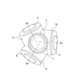
- FIG. 2 is a front view of the linear actuator as viewed from the direction II in FIG.
- the linear actuator shown in these drawings mainly includes a screw shaft 1, a plurality of rollers 2, and a roller cage 3.
- a screw thread 10 formed in a spiral shape is provided on the outer periphery of the screw shaft 1.
- the flank surfaces 1 a and 1 b of the screw thread 10 are inclined with respect to the central axis of the screw shaft 1.
- the screw thread 10 in the present embodiment has a trapezoidal cross section, and the surface on the radially outer side of the screw shaft 1 is substantially parallel to the central axis of the screw shaft 1.
- inclined flank surfaces 1 a and 1 b spread toward the screw shaft 1 from both ends of the parallel surfaces.
- the screw thread 10 formed in this way forms a screw groove on the outer periphery of the screw shaft 1, and the screw shaft 1 is a male screw.
- the right flank surface in FIG. 1 is referred to as a right flank surface 1a
- the left flank surface is referred to as a left flank surface 1b as appropriate.
- the roller cage 3 In the roller cage 3, a female screw portion 31 corresponding to the male screw of the screw shaft 1 is formed, and the screw shaft 1 is inserted into the roller cage 3 via the female screw portion 31. Further, as shown in FIG. 2, the roller cage 3 includes a plurality of substantially cylindrical projecting portions 3a projecting outward in the radial direction of the screw shaft 1 (more specifically, in the direction of the central axis of each roller 2). 3b, 3c.
- it is set as the protrusion part 3a, the protrusion part 3b, and the protrusion part 3c in order from the near side to the paper surface.
- the protrusion 3b moves the protrusion 3a to the right in FIG.
- the lead L is shifted by a quarter of the drawing for convenience.
- the roller 2, the cylindrical roller bearings 4 and 5, and the cover 6 are shown in a plane including the central axis 26 of the roller 2.
- the cross section of the female screw portion 31 of the roller cage 3 in a plane including the central axis of the screw shaft 1 is illustrated.
- Rollers 2 are housed in the projecting portions 3a, 3b, 3c via rolling bearings (cylindrical roller bearings 4, 5 described later) so as to be able to rotate, and the openings of the projecting portions 3a, 3b, 3c are respectively covered. 6 is occluded.
- the cover 6 is fixed to the roller cage 3 by fixing means (not shown) such as bolts.
- the roller cage 3 and the screw shaft 1 are in contact only via the rolling surfaces 2c of the plurality of rollers 2 housed in the roller cage 3, and are not in contact with each other.
- the roller cage 3 rotates relative to the screw shaft 1 around the screw shaft 1, and a relative linear motion is generated between the screw shaft 1 and the roller cage 3.
- roller cage 3 of the present embodiment three protrusions 3a, 3b, and 3c are provided to house the three rollers 2 from the viewpoint of giving priority to production ease.
- the number of rollers 2) may be appropriately increased or decreased according to the magnitude of the axial thrust to be applied.
- the female thread portion 31 When the female thread portion 31 is formed in this way, when the axial thrust Fth is acting in the direction shown in FIG. 1 (the right direction in FIG. 1), the axial thrust Fth is always transmitted via the roller 2 to the roller cage. 3 can be transmitted. Therefore, if the female thread portion 31 is formed as described above, the relative rotation and axial movement performed between the screw shaft 1 and the roller cage 3 can be performed with a rolling pair with a small friction loss. If the female thread portion 31 is formed as described above, even if the axial thrust Fth acts in the opposite direction to FIG. 1 (that is, the left direction in FIG. 1), Since the left flank surface 1b having a small gap immediately comes into contact with the female threaded portion 31, play caused by the axial thrust Fth can be suppressed to a small level.
- Each roller 2 rotates about the central shaft 26 and rolls on the right flank surface 1a, a rotating shaft 2a protruding from the rolling portion 2e and having the central shaft 26 at its center,
- the portion 2e includes an inner end surface 2d that is an end surface on the screw shaft 1 side, and an outer end surface 2b that is an end surface on the cover 6 side of the rotating shaft 2a.
- a rolling surface 2c that contacts the right flank surface 1a is provided in the circumferential direction of the rolling portion 2e, and the rolling portion 2e rolls on the right flank surface 1a via the rolling surface 2c.
- each roller 2 is fixed to the roller cage 3 so that a straight line obtained by virtually extending the central shaft 26 maintains a posture intersecting with the screw shaft 1.
- the central axis 26 of the roller 2 is located on a plane A that intersects the central axis of the screw shaft 1 at an angle ⁇ substantially equal to the lead angle ⁇ ′ (see FIG. 1) of the screw thread 10. It can also be expressed as Here, the reason why the angle ⁇ at which the plane A intersects the central axis of the screw shaft 1 is “approximately” equal to the lead angle ⁇ ′ is as follows.
- the lead angle ⁇ ′ is obtained from the intersection line between a predetermined cylindrical surface having a constant distance from the central axis of the screw shaft 1 and the right flank surface 1a.
- a predetermined range that is, the height of the screw thread 10
- the lead angle ⁇ ′ also has a value within a predetermined range. For this reason, it is difficult to precisely correspond the angle ⁇ and the lead angle ⁇ ′.
- the lead angle ⁇ ′ is an angle formed by a tangent line of the right flank surface 1a indicated by a dashed line B in FIG. 1 and a straight line perpendicular to the central axis of the screw shaft 1, the dashed line B and the plane A are Nearly orthogonal. That is, the plane A is substantially orthogonal to the right flank surface 1a.
- the central axis 26 of the roller 2 in the protrusions 3a and 3b is also within a plane that intersects with the central axis of the screw shaft 1 at an angle ⁇ , similarly to the roller 2 in the protrusion 3b.
- each roller 2 in the present embodiment is held in a posture inclined toward the thread 10 side with which the rolling surface 2c is in contact with the above posture. That is, the central axis 26 is inclined in the plane A toward the contact portion between the rolling surface 2c and the right flank surface 1a.
- the central axis 26 is tilted to the right flank surface 1a in this way, the outer side of the screw thread 10 that is in contact with the rolling surface 2c and an interval of one pitch (in the protrusion 3a in FIG. 1). Since the inner end surface 2d of the roller 2 can be disposed above the roller 2, the diameter of the rolling portion 2e of the roller 2 (more specifically, the inner end surface 2d (Diameter) can be increased.
- the diameter of the inner end face 2d can be made larger than the pitch of the thread 10 (which also corresponds to the lead L in the present embodiment), so that the thread 10 in contact with the rolling surface 2c can be made.
- the adjacent screw thread 10 and the inner end face 2d can be made to face each other. Therefore, if the center shaft 26 of the roller 2 is held in a posture inclined toward the thread 10 as described above, the diameter of the rolling portion 2e can be increased, and thus the rolling surface 2c and the right flank surface 1a are generated. Hertz stress can be reduced.
- a mortar-shaped recess is formed on the inner end face 2d as in the present embodiment. It is preferable. This is because if the recess is formed in the inner end face 2d in this way, it is possible to avoid the inner end face 2d from coming into contact with the screw thread 10. Further, when the concave portion is formed in the inner end face 2d in this way, even if the amount of inclination when the central shaft 26 of the roller 2 is inclined toward the thread 10 is small, it is possible to avoid interference with the thread 10 at the next pitch. It becomes like this. By reducing the amount of inclination of the central shaft 26 in this way, the outer diameter of the roller cage 3 can be kept small even if the diameter of the rolling part 2e is the same.
- each roller 2 is formed so as to be in contact with the right flank surface 1a within a certain range in the direction of the central axis 26.
- Hertzian stress is reduced and durability against flaking can be improved.
- each roller 2 is moved within a certain range in the direction of the central axis 26.
- the diameter of the rolling part 2e may be formed so as to gradually decrease in accordance with the shape of the right flank surface 1a as it approaches the screw shaft 1.
- the contact portion between the rolling portion 2e and the right flank surface 1a is secured as long as possible and the two are in line contact.
- the diameter of the rolling part 2e of the present embodiment decreases at a constant rate in accordance with the shape of the screw thread 10 (ie, trapezoid) as it approaches the screw shaft 1 within a certain range in the direction of the central axis 26.
- the rolling part 2e is formed by a part of a cone co (see FIG. 1). That is, the rolling surface 2c is formed by a part of the side surface of the cone co, and the rolling portion 2e is in line contact with the right flank surface 1a over the entire area.
- the apex angle of the cone co defined by the rolling surface 2c is 2 ⁇
- the angle between the contact line between the rolling surface 2c and the right flank surface 1a and the central axis of the screw shaft 1 is ⁇ .
- ⁇ represents the inclination direction of the right flank surface 1a in the cross section in the plane including the contact line.
- the center of the flank surface 1a and the screw shaft 1 displayed as the outline of the thread 10 in FIG. Strictly speaking, the angle formed by the axis is not ⁇ , but when the value of the angle ⁇ is small, it is approximately equal to ⁇ ).
- the sum of the angle ⁇ and the angle ⁇ is made smaller than ⁇ / 2 as in the roller 2 shown in FIG.
- the central axis 26 of the roller 2 is on the contact portion side between the rolling surface 2c and the right flank 1a. Can be tilted.
- the outer ring of the inner end face 2d of the roller 2 is at a right angle to the central axis 26, and therefore is inclined with respect to the central axis of the screw shaft 1.
- the diameter of the rolling portion 2e can be increased as described above, and the Hertz stress generated on the rolling surface 2c and the right flank surface 1a can be reduced. Can do.
- Each roller 2 is supported by a roller cage 3 via a radial rolling bearing 4 capable of supporting a radial load acting on the roller 2 and a thrust rolling bearing 5 capable of supporting a thrust load acting on the roller 2.
- the radial rolling bearing 4 in the present embodiment is a so-called cylindrical roller bearing, and is formed by a plurality of cylindrical rollers (rolling elements) arranged in a circle so as to surround the rotating shaft 2a from the circumferential direction.
- the radial rolling bearing 4 is sandwiched between the rotating shaft 2a of the roller and the inner walls of the protruding portions 3a, 3b, 3c.
- the thrust rolling bearing 5 in the present embodiment is a cylindrical roller bearing similar to the bearing 4 and is formed by a plurality of cylindrical rollers (rolling elements) arranged in a circle on the outer edge portion of the outer end surface 2b. .
- the thrust rolling bearing 5 is sandwiched between the outer end surface 2 b of the roller 2 and the cover 6.
- the radial load and the thrust load acting on the respective rolling bearings 4 and 5 that support the roller 2 are finally supported by the roller cage 3.
- the cylindrical roller of the rolling bearings 4 and 5 directly rolls on the surface of the rotating shaft 2a and the outer end surface 2b of the roller 2 as described above, it is preferable to increase the surface hardness by performing heat treatment.
- the flank surfaces 1a and 1b of the screw thread 10 are inclined with respect to the central axis of the screw shaft 1 as in the present embodiment, the contact portion between the rolling surface 2c of the roller 2 and the right flank surface 1a.
- a virtual straight line perpendicular to the right flank surface 1a is defined.
- the radial rolling bearing 4 is fixed to a position where the virtual straight line passes through a cylindrical space surrounded by a plurality of rolling elements forming the bearing 4. This point will be described below.
- a contact force F 1 acting on the right flank surface 1a from the rolling surface 2c is shown by an arrow extending perpendicularly to the right flank surface 1a from the center of the contact portion between the rolling surface 2c of the roller 2 and the right flank surface 1a.
- the contact forces F 1 ′, F 2 ′, and F 3 ′ are generated by the axial thrust Fth acting on the left end surface of the screw shaft 1 and the right end surface of the roller cage 3 in FIG. Since the rolling contact surface 2c and the right flank surface 1a in this embodiment are in line contact, the contact force is strictly a line distribution load, but here, for the sake of convenience, the resultant force represents the contact force. ing.
- contact reaction forces F 1 , F 2 (not shown), F 3 are applied from the right flank surface 1 a to the rolling surface 2 c because of the relationship between the contact forces F 1 ′, F 2 ′, F 3 ′ and the action reaction. Is working. F 1 and F 3 shown in FIG. 1 are forces of the same magnitude and opposite directions to F 1 ′ and F 3 ′. Therefore, F 1 , F 2 , and F 3 act on an action line that passes through the center of the contact portion between the rolling surface 2 c and the flank surface 1 a and is perpendicular to the contact portion, that is, on the virtual straight line.
- the thrust (axial) direction components (thrust loads F 1a , F 2a (not shown), F 3a ) of the contact reaction forces F 1 , F 2 , F 3 are applied to the outer end face 2b of the roller 2 and the cover. Since it can be supported by the thrust rolling bearing 5 sandwiched between 6, the contact reaction forces F 1 , F 2 , and F 3 acting on the roller 2 are converted into one radial rolling bearing 4 and one thrust rolling bearing 5. Can be supported. Thereby, since the number of the bearings for supporting the roller 2 can be suppressed, the manufacturing cost of the linear actuator can be suppressed. Although details will be described later, if the rolling bearing 4 can support both radial load and thrust load, the number of bearings can be further reduced.
- the radial rolling bearing 4 is arranged so that the virtual straight line intersects the central axis 26 of the roller 2 at the center in the width direction of the radial rolling bearing 4. Good.
- the contact reaction forces F1, F2, F3 and radial loads F 1r , F 2r , F 3r and thrust loads F 1a , F 2a , F 3 at the intersections of the virtual straight line and the central shaft 26 are formed. Can be decomposed into 3a .
- the radial loads F 1r , F 2r , F 3r can be applied to the center of the roller width of the radial rolling bearing 4, and the thrust loads F 1a , F 2a , F 3a can be applied to the center of the thrust rolling bearing 5.
- the contact reaction forces F 1 , F 2 , F 3 acting on the roller 2 can be supported without difficulty by one bearing 4 for radial load and one bearing 5 for thrust load.
- thrust loads F 1a , F 2a , and F 3a can be applied to the center of the thrust rolling bearing 5, so that the imaginary straight line simply passes through the radial rolling bearing 4.
- the point which can improve the lifetime of the thrust rolling bearing 5 is also a merit.
- either one of the screw shaft 1 and the roller cage 3 is not rotated about the axis by a slide key or the like but only in the axial direction. If it is configured to be movable and the other member is configured to be rotatable around the axis while being restrained from moving in the axial direction by a thrust bearing or the like, the screw shaft 1 and the roller cage 3 can function as a linear actuator. That is, when one rotatable member of the screw shaft 1 and the roller cage 3 is driven to rotate, an axial thrust can be generated in the other member. In the above description, if one member movable in the axial direction is driven in the axial direction, the other rotatable member can be driven to rotate.
- the center axis 26 of each roller 2 has a posture in which a straight line virtually extending the center axis 26 intersects the screw shaft 1 and the flank surface with which the rolling surface 2c comes into contact.
- the rolling surface 2c of the roller 2 is in contact with the flank surface 1a in a certain range in the direction of the central axis 26 of the roller 2 in a posture inclined to the 1a side.
- the roller 2 when the roller 2 is fixed so that the central shaft 26 is held in an inclined posture toward the flank surface 1a as described above, the thread 10 and the pitch 10 in contact with the rolling surface 2c are in one pitch.
- the inner end face 2d of the roller 2 can be arranged outside the thread 10 via the minute interval.
- the diameter of the rolling part 2e of the roller 2 can be increased as compared with the case where the central shaft 26 is not tilted. Therefore, the Hertz stress generated on the rolling surface 2c and the right flank surface 1a is reduced, and the roller 2 It is possible to improve the durability.
- the diameter of the rolling part 2e can be increased as described above, the load that can be supported by one roller 2 can be increased, and therefore, a constant axial thrust is supported as compared with the conventional technique. Therefore, the number of rollers 2 necessary for this can be reduced. Furthermore, if the Hertz stress is reduced as described above, the required hardness of the screw shaft 1 and the rolling surface 2c of the roller 2 is reduced, so that it is possible to reduce the manufacturing cost by omitting the heat treatment such as quenching that has been conventionally required. Occurs.
- the number of rollers 2 in contact with the screw thread 10 is three as in the present embodiment, even if there are some dimensional errors in the components compared to the case where four or more rollers 2 are provided. Since all the rollers 2 can reliably contact the thread 10 and support the load, the production becomes easy. This also makes it difficult for variations in power transmission efficiency and durability caused by the product to be produced or not produced.
- the present embodiment corresponds to a structure obtained by replacing the rolling bearings 4 and 5 in the first embodiment with other bearings (conical roller bearings 14).
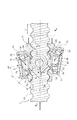
- FIG. 3 is a side sectional view of a linear actuator according to a second embodiment of the present invention.
- symbol is attached
- each roller 2 shown in this figure is rotatably supported in the roller cage 3 via only one conical roller bearing 14.
- the conical roller bearing 14 is configured by a plurality of rolling elements (conical rollers) having a conical shape, so that the contact reaction forces F 1 , F 2 , and F 3 are reduced.
- the radial direction components radial loads F 1r , F 2r , F 3r
- the thrust direction components thrust loads F 1a , F 2a , F 3a
- the conical roller bearing 14 has a roller cage via a retaining ring 15 so that an imaginary straight line perpendicular to the flank surface 1a passes through a space surrounded by the conical rollers at the contact portion between the roller 2 and the flank surface 1a. 3 is fixed. That is, the lines of action of the contact reaction forces F 1 , F 2 , and F 3 in the present embodiment pass through the space surrounded by the conical rollers, so that only one conical roller bearing 14 is used for the roller 2. Can be supported.
- the number of bearings can be further reduced as compared with the case of the first embodiment.
- the manufacturing cost can be further suppressed.
- the intersection point between the line of action of the contact reaction forces F 1 and F 3 and the central axis 26 of the roller 2 is the position indicated in the catalog as the point of action of the load on the conical roller bearing 14. Arranged in the vicinity.
- the radial load components F 1r and F 3r and the thrust load components F 1a and F 3a of the forces F 1 and F 3 can be supported without difficulty by using only one conical roller bearing 14.
- the conical roller bearing 14 is exemplified as a rolling bearing capable of supporting both a radial load and a thrust load. May be.
- the tip portion of the screw thread 10 is accommodated in the recess provided in the inner end surface 2d of the roller 2 of the present embodiment.
- the screw thread 10 is housed in the roller 2 in this way, the size of the roller cage 3 can be reduced.
- This embodiment relates to the size of the rolling portion 2e of the roller 2 and the flank surface 1a of the screw thread 10. By optimizing them, the slip generated between the roller 2 and the screw thread 10 is suppressed. I am trying.
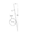
- FIG. 4 is a side sectional view of a linear actuator according to a third embodiment of the present invention.
- the linear actuator shown in FIG. 4 corresponds to a part of the linear actuator shown in FIG.
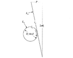
- a point belonging to the contact portion between the right flank surface 1a and the rolling surface 2c and located on the outermost peripheral side in the radial direction of the screw shaft 1 is defined as an outer peripheral contact point P1, and the screw shaft 1 belonging to the contact portion is included.
- a point located on the innermost peripheral side in the radial direction of the inner contact point P3 is an inner peripheral contact point P3, a point belonging to the contact portion and located at the center of the outer peripheral contact point P1 and the inner peripheral contact point P3 is a central contact point P2,
- a point located at the center of the contact portion between the conical roller 14a and the inner ring 14b of the bearing 14 is defined as a central contact point P4, and a vertex of the cone co defined by a straight line passing through P1 and P3 and the central axis 26 is defined as a conical vertex P5 (that is, , P5 is an intersection of a straight line passing through P1 and P3 and the central axis 26), and these are indicated by black circles, respectively.
- the spiral for one lead passing through P1 with the center axis of the screw shaft 1 as the center is set as a spiral Lso
- the spiral for one lead passing through P3 with the center axis of the screw shaft 1 as the center is set as a spiral Lsi.
- a circle on the rolling surface 2c that passes through P1 with the center as a circle Lso, and a circle on the rolling surface 2c that passes through P3 with the center axis 26 as a center is a circle Lri, and these are indicated by broken lines.
- the radial distance from the central axis of the screw shaft 1 to P1 is Ro
- the radial distance from the central axis of the screw shaft 1 to P3 is Ri
- the distance from the conical vertex P5 to P1 is lo
- the conical vertex P5 Let the distance to P3 be li, and let the deviation amount between the central axis of the screw shaft 1 and the conical vertex P5 be ⁇ .
- FIG. 5 is a diagram showing the rolling distance of each part at point P1 in FIG. 4
- FIG. 6 is a diagram showing the rolling distance of each part at point P3 in FIG.
- FIG. 5 schematically shows a state in which the spiral Lso in FIG. 4 is developed on a plane and the circle Lso rolls thereon.
- FIG. 6 schematically shows a state in which the spiral Lsi in FIG. 4 is developed on a plane and the circle Lri rolls thereon.
- FIG. 7 is an explanatory diagram of a design theory for minimizing friction loss in the present embodiment.
- the process of calculating the value of ⁇ that satisfies equation (4) using this figure is shown.
- the horizontal axis x of the graph shown in FIG. 7 indicates the spiral arrangement radius R (that is, the distance from the helix to the central axis of the screw shaft 1), and the vertical axis y indicates the screw axis having an arbitrary spiral arrangement radius R and the lead L.
- the spiral length ls for one lead (one pitch) is shown.
- ls can be obtained by substituting an arbitrary spiral arrangement radius R and the value of the lead L of the screw shaft 1 into the following equation (5).
- the lead L is fixed to 20 mm, and ls is graphed as a function of R.
- ls can be approximated by a straight line as shown in FIG. In FIG.
- the roller 2 is provided so that the right flank surface 1a and the rolling part 2e are in contact with each other, and the conical vertex P5 is set to the central axis of the screw shaft 1. If the roller 2 is provided so as to be positioned on the opposite side of the roller 2, the roller 2 can be rolled with almost no slippage. Therefore, if the linear actuator is configured as described above, the power transmission efficiency can be further improved.
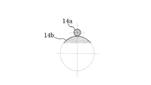
- FIG. 8 is a cross-sectional view of the vicinity of the rolling portion 2e of the roller 2 on the plane C in FIG. 4
- FIG. 9 is a cross-sectional view of the vicinity of the conical roller 14a of the bearing 14 on the plane C in FIG.
- the right flank surface 1a displayed in a substantially straight line has no curvature in the direction perpendicular to the paper surface, and may be considered as a flat surface as a Hertzian contact model.
- the rolling surface 2c of the roller 2 paired with the right flank surface 1a can be approximated by a cylindrical surface having a large radius as described above. Strictly speaking, the contact state between the right flank surface 1a and the rolling surface 2c is a line contact, but one (the right flank surface 1a) is a flat surface and the other (the rolling surface 2c) has a small curvature. The state is close to the surface contact state, and it can be easily estimated that the generation of Hertz stress is suppressed.
- the relatively small circle indicates the conical roller 14a
- the relatively large circle is the inner ring 14b.
- the contact between the conical roller 14a and the inner ring 14b can be approximated to the contact between the cylinders, but is a contact between the convex surface and the convex surface. Since the curvature of one of the cylinders (conical roller 14a) is large, the Hertzian stress increases. This is avoided by distributing the load with the conical roller 14a. In other words, it can be said that the right flank surface 1a and the rolling surface 2c of FIG. 8 transmit the load supported by the conical roller bearing 14 via the plurality of conical rollers 14a at one contact portion.
- the feature of the present embodiment is that not only the plurality of rollers 2 (first roller group) contacting the right flank surface 1a of the screw thread 10 but also the left flank surface of the screw thread 10 as compared with each of the above embodiments. It has a plurality of rollers (second roller group) in contact with 1b.
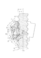
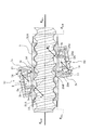
- FIG. 10 is a sectional side view of a linear actuator according to a fourth embodiment of the present invention.
- the vicinity of a female screw portion 31A (described later) of the roller cage 3 is shown as a cross section in a plane including the central axis of the screw shaft 1 for convenience.
- the linear actuator shown in this figure is arranged along the right flank surface 1a of the screw thread 10 at intervals in the circumferential direction of the screw shaft 1, and rolls on the right flank surface 1a via the rolling surface 2c.
- the first roller group 51 composed of a plurality of rollers 2 and the left flank surface 1b are arranged along the left flank surface 1b of the screw thread 10 at intervals in the circumferential direction of the screw shaft 1 and through the rolling surface 2Ac.
- a second roller group 52 composed of a plurality of rollers 2 ⁇ / b> A rolling on the upper side and a female screw portion 31 ⁇ / b> A formed to face the screw thread 10 of the screw shaft 1 on the inner peripheral portion of the roller cage 3 are provided.
- the roller 2 included in the first roller group 51 is configured in the same manner as the roller 2 of each of the above embodiments, and is in the protruding portions 3a, 3b (not shown), 3c (not shown) of the roller cage 3. And rolls in contact with the right flank surface 1a of the screw thread 10.
- Each roller 2 of the first roller group 51 acts in the right direction from the left end surface of the screw shaft 1, and a part of the axial thrust F th-R that balances the force shown on the right end surface of the roller cage 3. It is transmitted to the roller cage 3.
- F th-R a part of the axial thrust
- the roller 2A included in the second roller group 52 is accommodated in protrusions 3d, 3e (not shown), 3f (not shown) provided on the roller cage 3, and the left flank surface of the screw thread 10 Rolls in contact with 1b.
- the protruding portion 3e moves the protruding portion 3d to the left in FIG. 10 by one third of the lead L of the screw shaft 1 and
- the protrusion 3f is arranged at a position rotated by 120 degrees around the central axis, and the protrusion 3f is moved to the left in FIG. 10 by one third of the lead L from the position of the protrusion 3e, and the screw shaft.
- the protrusion 3d corresponds to the protrusion 3a
- the protrusion 3e corresponds to the protrusion 3b
- the protrusion 3f corresponds to the protrusion 3c.
- the roller accommodated in the protrusion part in such a corresponding relationship is comprised by point symmetry via the point on the central axis of the screw shaft 1.
- Each roller 2A of the second roller group 52 configured as described above acts in the left direction from the right end surface of the screw shaft 1, and an axial thrust F th ⁇ that balances the force illustrated on the left end surface of the roller cage 3. Part of L is transmitted to the roller cage 3.
- the female threaded portion 31A is formed with the right flank surface 1a in a state where each roller 2A of the second roller group 52 is in contact with the left flank surface 1b while each roller 2 of the first roller group 51 is in contact with the right flank surface 1a.
- the gap formed between the female screw portion 31A and the gap formed between the left flank surface 1b and the female screw portion 31A are formed to be sufficiently large.
- the axial thrust is applied to the first roller group 51 and the second roller even when the axial thrust acts from any axial direction of the screw shaft 1. It can be transmitted to the roller cage 3 via any one of the groups of rollers 52. That is, according to the present embodiment, the roller groups 51 and 52 and the thread 10 can be always brought into contact with each other by rolling, so that the friction loss can always be reduced regardless of the direction in which the axial thrust acts. Further, according to the present embodiment, even when the acting direction of the axial thrust is constant and a moment or a lateral load is applied, all the portions where the roller groups 51 and 52 and the screw thread 10 are in contact with each other are rolled. Therefore, the friction loss can be reduced.
- rollers 2 and 2A in this Embodiment are supported via the conical roller bearing 14, it cannot be overemphasized that you may support via the cylindrical roller bearing etc. which were mentioned above.
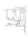
- FIG. 11 is a side view of a forklift provided with a linear actuator according to the present invention
- FIG. 12 is an enlarged view of the vicinity of the mast 70 in the forklift shown in FIG.
- the forklift shown in these drawings is attached to a vehicle body 60 on which a traveling device and a steering device are mounted, a mast 70 provided in front of the vehicle body 60, and an inner frame 72 (see FIG. 12) of the mast 70.
- Fork 80 is provided.
- a mast 70 includes an outer frame 71 attached to the front of the vehicle body 60, an inner frame 72 that is provided inside the outer frame 71 and moves up and down along the outer frame 71, and a linear actuator that moves the inner frame 72 up and down. 73 is provided.
- the linear actuator 73 includes a screw shaft 1 fixed to the outer frame 71, the roller cage 3, and a motor (drive source) 74 that rotationally drives the screw shaft 1.
- the roller cage 3 supports the inner frame 72 from below via a bracket 75 attached to the inner frame 72. Note that the motor 74 in the present embodiment transmits a driving force to the screw shaft 1 via a plurality of gears 76.
- the linear actuators described in the above embodiments can be used as height adjusting means of the fork 80 in the forklift.
- an electric actuator can be used as an actuator for a forklift that conventionally uses a hydraulic actuator.
Landscapes
- Engineering & Computer Science (AREA)
- Transportation (AREA)
- Structural Engineering (AREA)
- Mechanical Engineering (AREA)
- General Engineering & Computer Science (AREA)
- Geology (AREA)
- Civil Engineering (AREA)
- Life Sciences & Earth Sciences (AREA)
- Combustion & Propulsion (AREA)
- Chemical & Material Sciences (AREA)
- Transmission Devices (AREA)
- Forklifts And Lifting Vehicles (AREA)
- Rolling Contact Bearings (AREA)
Priority Applications (3)
| Application Number | Priority Date | Filing Date | Title |
|---|---|---|---|
| US13/145,827 US20120012425A1 (en) | 2009-01-23 | 2009-12-25 | Linear actuator and forklift truck |
| EP09838883A EP2390532A1 (en) | 2009-01-23 | 2009-12-25 | Linear actuator and forklift |
| CN200980155130XA CN102292568A (zh) | 2009-01-23 | 2009-12-25 | 直线运动执行器及叉车 |
Applications Claiming Priority (2)
| Application Number | Priority Date | Filing Date | Title |
|---|---|---|---|
| JP2009013006A JP5284124B2 (ja) | 2009-01-23 | 2009-01-23 | リニアアクチュエータ及びフォークリフト |
| JP2009-013006 | 2009-01-23 |
Publications (1)
| Publication Number | Publication Date |
|---|---|
| WO2010084693A1 true WO2010084693A1 (ja) | 2010-07-29 |
Family
ID=42355756
Family Applications (1)
| Application Number | Title | Priority Date | Filing Date |
|---|---|---|---|
| PCT/JP2009/071682 WO2010084693A1 (ja) | 2009-01-23 | 2009-12-25 | リニアアクチュエータ及びフォークリフト |
Country Status (6)
Cited By (2)
| Publication number | Priority date | Publication date | Assignee | Title |
|---|---|---|---|---|
| US20130160583A1 (en) * | 2011-12-22 | 2013-06-27 | Hitachi, Ltd. | Roller Screw |
| CZ310045B6 (cs) * | 2022-07-19 | 2024-06-12 | České vysoké učení technické v Praze | Pohybový závitový mechanizmus |
Families Citing this family (9)
| Publication number | Priority date | Publication date | Assignee | Title |
|---|---|---|---|---|
| JP5178675B2 (ja) * | 2009-09-28 | 2013-04-10 | 日立建機株式会社 | リニアアクチュエータ |
| JP2012189172A (ja) * | 2011-03-11 | 2012-10-04 | Hitachi Constr Mach Co Ltd | リニアアクチュエータ装置 |
| JP5824530B2 (ja) | 2011-12-14 | 2015-11-25 | 株式会社日立製作所 | ローラねじ |
| JP6016534B2 (ja) * | 2012-09-03 | 2016-10-26 | ユニキャリア株式会社 | 電動式リフト装置およびこの電動式リフト装置を使用したフォークリフト |
| WO2017015046A1 (en) | 2015-07-17 | 2017-01-26 | Crown Equipment Corporation | Processing device having a graphical user interface for industrial vehicle |
| EP4180928B1 (en) | 2016-11-22 | 2025-01-01 | Crown Equipment Corporation | User interface device for industrial vehicle |
| EP3591262B1 (en) | 2017-04-12 | 2022-08-24 | Goodrich Actuation Systems Limited | Linear actuator |
| JP7092469B2 (ja) * | 2017-06-29 | 2022-06-28 | 日本電産サンキョー株式会社 | 産業用ロボットのハンドおよび産業用ロボット |
| EP4212473B1 (en) | 2022-01-13 | 2024-04-17 | Tata Consultancy Services Limited | Chassis with an integrated fork assembly for autonomous mobile robots and autonomous guided vehicles |
Citations (5)
| Publication number | Priority date | Publication date | Assignee | Title |
|---|---|---|---|---|
| JPS60136661A (ja) * | 1983-12-24 | 1985-07-20 | Kazuo Fujita | ロ−ラスクリユウ |
| JPS6140770U (ja) * | 1984-08-20 | 1986-03-14 | ソニー株式会社 | ヘツドのねじ送り機構 |
| JP2001106493A (ja) * | 1999-10-08 | 2001-04-17 | Murata Mach Ltd | 無人フォークリフト |
| JP2004190767A (ja) | 2002-12-10 | 2004-07-08 | Nsk Ltd | ローラねじ装置 |
| WO2007066965A1 (en) * | 2005-12-07 | 2007-06-14 | Winner Bearings Co., Ltd. | Bearing screw feed device |
Family Cites Families (11)
| Publication number | Priority date | Publication date | Assignee | Title |
|---|---|---|---|---|
| US431067A (en) * | 1890-07-01 | Anti-friction gearing for threaded rods | ||
| US1407124A (en) * | 1920-08-24 | 1922-02-21 | William C Carr | Elevator truck |
| US2488256A (en) * | 1944-03-07 | 1949-11-15 | Electrolux Corp | Ball bearing jack screw |
| US2393764A (en) * | 1944-04-22 | 1946-01-29 | Frank Louis | Adjustable nut |
| US2938400A (en) * | 1956-02-02 | 1960-05-31 | John T Gondek | Screw thread |
| CH437700A (fr) * | 1965-07-22 | 1967-06-15 | Villars Julio | Elévateur pour automobiles |
| DE3225496A1 (de) * | 1982-07-08 | 1984-01-12 | AMD-Vertriebsgesellschaft für Antriebstechnik mbH, 5800 Hagen | Linearantrieb mit gewindespindel und waelzringmutter |
| US5533417A (en) * | 1993-04-12 | 1996-07-09 | Hughes Aircraft Company | Leadscrew assembly |
| SE505153C2 (sv) * | 1996-08-23 | 1997-07-07 | Kolungen Ab | Element för omvandlande av en skruvspindels vridrörelse till axiell rörelse hos en mutter |
| US7143661B2 (en) * | 2002-10-15 | 2006-12-05 | Raytheon Company | Leadscrew mechanical drive with differential leadscrew follower structure and brake |
| US20090308192A1 (en) * | 2008-06-17 | 2009-12-17 | Hiwin Technologies Corp. | Ball screw device having bearing members of different load |
-
2009
- 2009-01-23 JP JP2009013006A patent/JP5284124B2/ja not_active Expired - Fee Related
- 2009-12-25 US US13/145,827 patent/US20120012425A1/en not_active Abandoned
- 2009-12-25 CN CN200980155130XA patent/CN102292568A/zh active Pending
- 2009-12-25 WO PCT/JP2009/071682 patent/WO2010084693A1/ja active Application Filing
- 2009-12-25 EP EP09838883A patent/EP2390532A1/en not_active Withdrawn
- 2009-12-25 KR KR1020117017030A patent/KR20110119653A/ko not_active Withdrawn
Patent Citations (5)
| Publication number | Priority date | Publication date | Assignee | Title |
|---|---|---|---|---|
| JPS60136661A (ja) * | 1983-12-24 | 1985-07-20 | Kazuo Fujita | ロ−ラスクリユウ |
| JPS6140770U (ja) * | 1984-08-20 | 1986-03-14 | ソニー株式会社 | ヘツドのねじ送り機構 |
| JP2001106493A (ja) * | 1999-10-08 | 2001-04-17 | Murata Mach Ltd | 無人フォークリフト |
| JP2004190767A (ja) | 2002-12-10 | 2004-07-08 | Nsk Ltd | ローラねじ装置 |
| WO2007066965A1 (en) * | 2005-12-07 | 2007-06-14 | Winner Bearings Co., Ltd. | Bearing screw feed device |
Cited By (2)
| Publication number | Priority date | Publication date | Assignee | Title |
|---|---|---|---|---|
| US20130160583A1 (en) * | 2011-12-22 | 2013-06-27 | Hitachi, Ltd. | Roller Screw |
| CZ310045B6 (cs) * | 2022-07-19 | 2024-06-12 | České vysoké učení technické v Praze | Pohybový závitový mechanizmus |
Also Published As
| Publication number | Publication date |
|---|---|
| JP5284124B2 (ja) | 2013-09-11 |
| EP2390532A1 (en) | 2011-11-30 |
| KR20110119653A (ko) | 2011-11-02 |
| CN102292568A (zh) | 2011-12-21 |
| US20120012425A1 (en) | 2012-01-19 |
| JP2010169205A (ja) | 2010-08-05 |
Similar Documents
| Publication | Publication Date | Title |
|---|---|---|
| JP5284124B2 (ja) | リニアアクチュエータ及びフォークリフト | |
| CN103994184B (zh) | 封闭型摆线精密减速器 | |
| JP5178675B2 (ja) | リニアアクチュエータ | |
| US20130202234A1 (en) | Slewing bearing structure | |
| US20140199171A1 (en) | Large rolling bearing | |
| US9188211B2 (en) | Roller screw | |
| US10670072B2 (en) | Rolling bearing | |
| JP5300978B2 (ja) | リニアアクチュエータ及びフォークリフト | |
| JP5345587B2 (ja) | 回転直動変換機構 | |
| JP6545489B2 (ja) | トリポード型等速自在継手 | |
| US9822814B2 (en) | Bearing for combined loads | |
| JP5875876B2 (ja) | 歯車伝動装置 | |
| CN101836000B (zh) | 三脚接头和用于三脚接头的滚柱体 | |
| CN203453296U (zh) | 车轮支承用滚动轴承单元 | |
| JP5862162B2 (ja) | タンデムアンギュラ型玉軸受 | |
| JP2016200218A (ja) | 遊星ローラ式の動力伝達装置 | |
| JP2006177447A (ja) | 複列転がり軸受 | |
| JP2012172784A (ja) | 玉軸受 | |
| JP4901556B2 (ja) | トラクションドライブ機構 | |
| JPWO2006112378A1 (ja) | 円筒ころ軸受 | |
| TW202100892A (zh) | 軸承與減速機 | |
| JP2025038796A (ja) | アンギュラ玉軸受および回転機構 | |
| JP2004108429A (ja) | 円すいころ軸受 | |
| JP7112817B2 (ja) | 遊星ローラ式変速モータ | |
| JP2009052647A (ja) | 旋回リング |
Legal Events
| Date | Code | Title | Description |
|---|---|---|---|
| WWE | Wipo information: entry into national phase |
Ref document number: 200980155130.X Country of ref document: CN |
|
| 121 | Ep: the epo has been informed by wipo that ep was designated in this application |
Ref document number: 09838883 Country of ref document: EP Kind code of ref document: A1 |
|
| DPE2 | Request for preliminary examination filed before expiration of 19th month from priority date (pct application filed from 20040101) | ||
| WWE | Wipo information: entry into national phase |
Ref document number: 2009838883 Country of ref document: EP |
|
| ENP | Entry into the national phase |
Ref document number: 20117017030 Country of ref document: KR Kind code of ref document: A |
|
| NENP | Non-entry into the national phase |
Ref country code: DE |
|
| WWE | Wipo information: entry into national phase |
Ref document number: 13145827 Country of ref document: US |