WO2010082386A1 - エアバッグ及びエアバッグ装置 - Google Patents
エアバッグ及びエアバッグ装置 Download PDFInfo
- Publication number
- WO2010082386A1 WO2010082386A1 PCT/JP2009/067745 JP2009067745W WO2010082386A1 WO 2010082386 A1 WO2010082386 A1 WO 2010082386A1 JP 2009067745 W JP2009067745 W JP 2009067745W WO 2010082386 A1 WO2010082386 A1 WO 2010082386A1
- Authority
- WO
- WIPO (PCT)
- Prior art keywords
- airbag
- panel
- exhaust port
- exhaust
- gas
- Prior art date
- Legal status (The legal status is an assumption and is not a legal conclusion. Google has not performed a legal analysis and makes no representation as to the accuracy of the status listed.)
- Ceased
Links
Images




Classifications
-
- B—PERFORMING OPERATIONS; TRANSPORTING
- B60—VEHICLES IN GENERAL
- B60R—VEHICLES, VEHICLE FITTINGS, OR VEHICLE PARTS, NOT OTHERWISE PROVIDED FOR
- B60R21/00—Arrangements or fittings on vehicles for protecting or preventing injuries to occupants or pedestrians in case of accidents or other traffic risks
- B60R21/02—Occupant safety arrangements or fittings, e.g. crash pads
- B60R21/16—Inflatable occupant restraints or confinements designed to inflate upon impact or impending impact, e.g. air bags
- B60R21/23—Inflatable members
- B60R21/239—Inflatable members characterised by their venting means
Definitions
- the present invention relates to an airbag and an airbag apparatus mounted on a vehicle such as an automobile, and more particularly to an airbag and an airbag apparatus characterized by opening / closing means for vent holes of the airbag.
- an airbag device for absorbing an impact generated by an occupant by inflating and deploying an airbag in a vehicle at the time of a collision or sudden deceleration has become common.
- Such an airbag device includes an airbag device for a driver seat installed in a steering wheel, an airbag device for a passenger seat installed in an instrument panel, a side airbag device installed in a vehicle side or seat, and an upper door portion.
- Various types have been developed and adopted, such as an interior curtain airbag device, a knee airbag device corresponding to an occupant's knee, and a pedestrian airbag device installed under a hood.
- These airbag apparatuses generally include a gas generator that generates gas under a predetermined condition, an airbag that is connected to the gas generator and inflates and deploys, and a retainer that accommodates the airbag. Further, an exhaust port called a vent hole may be formed in the outer shell forming the airbag. The vent hole has a function of preventing the internal pressure of the airbag from becoming excessively high, and exhausting the gas in the airbag when the occupant contacts the airbag to alleviate the impact.
- the airbag apparatus in which such a vent hole is formed has a problem that the pressure loss is large because gas is exhausted from the vent hole during the inflation and deployment of the airbag.
- an airbag device for solving such problems for example, those described in Patent Document 1 and Patent Document 2 have already been proposed.
- the airbag described in Patent Document 1 has a tube made of a part of a fabric (woven fabric) of an airbag.
- the tube has entered the inside of the airbag, and its tip is held by a clamp.
- the submerged tip is configured to be able to jump out of the airbag body when the holding by the clamp is released.
- the airbag apparatus described in Patent Document 2 also has an exhaust tube connected to the outer shell of the airbag (for example, FIGS. 11A and 11B), similarly to the airbag described in Patent Document 1. .
- the exhaust tube is pulled inside the airbag by a strap, and when the anchor that fixes the strap is released, the exhaust tube is opened to the outside of the airbag and acts as a vent hole.
- a tube-shaped exhaust port drawn into the airbag is formed in the vent hole until the tube is released to the outside of the airbag. Can suppress the exhaust of gas.
- a holding mechanism for holding the tip of the tube in the airbag is necessary and difficult to assemble, (2) until the tube is released to the outside after the holding mechanism is released.
- the internal pressure of the airbag becomes too high due to the time required for this, and (3) the tube may not be released to the outside due to deformation of the airbag or pressing against the inner surface of the airbag due to gas pressure, etc. is there.
- the problem (3) does not function as a vent hole, or the problem (2) becomes more prominent.
- the present invention has been made in view of the above-described problems, and an object thereof is to provide an airbag and an airbag apparatus that can be easily assembled to an airbag and can exhaust gas in accordance with the internal pressure of the airbag. .
- the airbag in an airbag that is inflated and deployed by supplying gas therein, the airbag has an opening formed in the airbag, and a cylindrical exhaust port connected to the opening, There is provided an airbag characterized in that the exhaust port is configured to be easily folded in a predetermined direction.
- an air generator comprising: a gas generator that generates gas under a predetermined condition; an airbag that is connected to the gas generator and is inflated and deployed; and a retainer that accommodates the airbag.
- the airbag has an opening formed in the airbag and a cylindrical exhaust port connected to the opening, and the exhaust port is easily broken in a predetermined direction.
- the exhaust port includes a first panel disposed outside the folding direction and a second panel disposed inside the folding direction, and the second panel is
- the first panel may be made of a material having a lower rigidity
- the first panel may be formed thicker than the second panel
- the second panel may be made thicker than the first panel. You may form so that elongation may become high.
- the exhaust port has a substantially conical curved surface portion that is gradually reduced in diameter from the opening, and an exhaust nozzle portion having a diameter that is equal to or larger than the minimum diameter of the substantially conical curved surface portion.
- the apex of the cone constituting the substantially conical curved surface portion is set so as to be located in the exhaust nozzle portion.
- the distance from the upper end of the substantially conical curved surface portion to the vertex is set to be half or less of the length of the exhaust nozzle portion.
- the exhaust nozzle part may be formed so as to gradually increase in diameter toward the tip part.
- the exhaust nozzle part has a guide part connected to the airbag located inside the folding direction so as to maintain a state in which the exhaust nozzle part is inclined to the side where it easily breaks in a gas exhaust state. It may be configured.
- the exhaust port includes a first panel disposed outside the folding direction and a second panel disposed inside the folding direction, and the first panel and The second panel is formed so as to have a substantially chevron shape when combined, and may be sewn to the opening in a state where both ends of the second panel overlap each other.
- the exhaust port of the airbag is folded in a direction in which it is easily broken outside the airbag and accommodated in the retainer.
- the exhaust port configured to be easily folded in a predetermined direction
- the exhaust port is bent until a predetermined pressure is applied to the exhaust port.
- the state can be maintained, and the exhaust of gas in the airbag can be suppressed.
- the bent portion of the exhaust port immediately rises and the gas can be exhausted quickly.
- one of the panels constituting the exhaust port is made of a material having low rigidity, is formed thick, or is formed so as to have high elongation, so that it can be easily broken in a predetermined direction.
- An exhaust port can be formed.
- a low rigidity material and a panel configured to have high elongation are more susceptible to gas pressure than the other panel, and the other panel is attracted in the direction of bending, making it easier to suppress gas exhaust. be able to.
- the exhaust port can be easily bent in the vicinity of the apex of the substantially conical curved surface portion, and gas exhaust can be easily suppressed.
- the distance from the upper end to the apex of the substantially conical curved surface part is equal to or less than half the length of the exhaust nozzle part, it is possible to easily form an exhaust port that is easily bent.
- the throat part is configured at the exhaust port, making it easier to bend near the seam, and when a predetermined pressure is reached Gas can be easily exhausted.
- the position of the exhaust port and the gas exhaust direction during gas exhaust can be stabilized. Furthermore, by forming the panel constituting the exhaust port in a substantially chevron shape, it is possible to reinforce the connection portion of the exhaust port that is easily loaded with pressure and to suppress gas leakage.
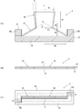
- FIG. 1 It is a figure which shows the exhaust mechanism part of the airbag which concerns on this invention, (A) has shown the locked state, (B) has shown the exhaust state. It is a block diagram of an exhaust port, (A) is a front view, (B) is a top view, and (C) shows a top view in a connected state. It is a figure which shows the effect
- FIG. 1 is a figure which shows the exhaust mechanism part of the airbag which concerns on this invention, (A) has shown the locked state, (B) has shown the exhausted state.
- 2A and 2B are configuration diagrams of the exhaust port, where FIG. 2A is a front view, FIG. 2B is a top view, and FIG. 2C is a top view in a connected state.
- the airbag 1 of the present invention shown in FIGS. 1A and 1B has an opening 2 formed in the airbag 1 and a cylindrical exhaust port 3 connected to the opening 2.
- the exhaust port 3 is configured to be easily bent in a predetermined direction.
- the exhaust port 3 includes a first panel 31 disposed on the outer side in the folding direction and a second panel 32 disposed on the inner side in the folding direction.
- the first panel 31 is a second panel. It is formed thicker than the panel 32.
- the exhaust port 3 has a substantially conical curved surface portion 33 gradually reduced in diameter from the opening 2 and an exhaust nozzle portion 34 having a diameter equal to or larger than the minimum diameter Rn of the substantially conical curved surface portion 33, and has a substantially conical curved surface.
- the apex P of the cone constituting the part 33 is set so as to be located in the exhaust nozzle part 34.
- the opening 2 has a slit shape or a slot shape formed in the base fabric 11 constituting the outer shell of the airbag 1.
- the opening 2 is kept closed until the airbag 1 is inflated and deployed.
- FIG. 1A when the gas in the airbag 1 flows into the exhaust port 3 and the substantially conical curved surface portion 33 is inflated and deployed in a substantially conical shape, the opening 2 becomes the shape of the exhaust port 3.
- a substantially circular shape is opened.
- the exhaust port 3 has, for example, the configuration shown in FIG.
- the exhaust port 3 shown in FIG. 2 includes a first panel 31 disposed on the outer side in the folding direction and a second panel 32 disposed on the inner side in the folding direction.
- the first panel 31 is formed to be thicker than the second panel 32 while being formed of a woven fabric of the same material (for example, a nylon yarn woven fabric coated with a resin coating).
- the first panel 31 and the second panel 32 have a thickness t1> if the thickness of the first panel 31 is t1 and the thickness of the second panel 32 is t2. It is formed to have a thickness t2.
- the thicknesses t1 and t2 of the first panel 31 and the second panel 32 are adjusted by changing the weaving method of the nylon yarn and the thickness of the nylon yarn.
- the folding direction of the first panel 31 disposed outside the folding direction is increased. It can set so that the rigidity of the 2nd panel 32 arrange
- the first panel 31 and the second panel 32 have a surplus that constitutes a joint between the substantially conical curved surface portion 33, the exhaust nozzle portion 34, and the opening 2 of the airbag 1. And a meat portion 35 (shaded portion in the figure).
- a meat portion 35 shaded portion in the figure.
- an angle formed between the generatrix of the substantially conical curved surface portion 33 and the center line L is ⁇
- an angle formed between the generatrix of the exhaust nozzle portion 34 and the center line L (parallel line thereof) is ⁇
- the approximately conical curved surface portion 33 is formed.
- Rd is the radius of the lower bottom portion
- Ru is the radius of the upper bottom portion of the exhaust nozzle portion 34
- Rn is the minimum diameter of the exhaust port 3
- Hc is the height of the substantially conical curved surface portion 33
- the height of the apex P of the substantially conical curved surface portion 33 The height (distance from the upper end of the substantially conical curved surface portion 33 to the apex P) is Hp
- the height (length) of the exhaust nozzle portion 34 is Hn.
- the height Hp of the apex P is set to the exhaust nozzle portion so that the exhaust nozzle portion 34 does not stand up due to gas pressure fluctuations during inflation and deployment of the airbag 1 before the occupant or in-vehicle structure comes into contact with the airbag 1. It is preferable that the height is set to be not more than half of the height Hn of 34, preferably in the range of 1/3 to 1/2. Further, the exhaust nozzle portion 34 is set so that the radius Ru ⁇ radius Rn or the angle ⁇ ⁇ 0 ° so as not to hinder the gas flow during exhaust, and gradually increases in diameter toward the tip portion. It is preferable to form. Further, when the radius Rd is about 120 to 130 mm, it is effective to set the angle ⁇ to around 30 °.
- the first panel 31 and the second panel 32 are formed so as to form a substantially mountain shape when the two panels are combined, and are indicated by hatched portions in the figure.
- the part constitutes the surplus part 35.
- the surplus portion 35 is a portion that is sewn to the base fabric 11 of the airbag 1.
- the left and right end portions of the mountain shape are respectively constituted by a convex portion 31R of the first panel 31 and a convex portion 32L of the second panel 32.
- the convex portions 31R and 32L form a wrap portion w (shaded portion in the drawing) that overlaps the other surplus portion 35 at the time of sewing, and has a function of reinforcing the joint portion.
- the exhaust nozzle portion 34 and the substantially conical curved surface portion 33 of the first panel 31 and the second panel 32 are indicated by a one-dot chain line. After passing through one opening 2, the surplus portion 35 is widened and stitched to the base fabric 11 of the airbag 1.
- an exhaust mechanism having a structure that easily breaks in a predetermined direction (second panel 32 side) is formed. can do. Therefore, the exhaust port 3 can be maintained in a bent state until a predetermined pressure is applied to the exhaust port 3, and the exhaust of the gas in the airbag 1 can be suppressed.
- the folding direction of the exhaust port 3 is set to the direction away from a passenger
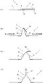
- FIG. 3 is a figure which shows the effect
- (A) is before expansion
- (B) is in inflating and deploying (low pressure)
- (C) is in inflating and deploying (pressure) (Large) and (D) show the gas exhaust state.
- the exhaust port 3 is connected to the base fabric 11 of the airbag 1 by a surplus portion 35 and is easily broken outside the airbag 1 (on the second panel 32 side). It is folded and accommodated in a retainer (not shown). By folding in such a direction that it is easy to break, the exhaust port 3 can be folded. Although not shown, the exhaust port 3 may be folded so that the exhaust nozzle portion 34 is sandwiched between the substantially conical curved surface portion 33 and the base cloth 11. Before the airbag 1 is inflated and deployed, as shown in FIG. 3A, the opening 2 is kept closed.
- the opening 2 gradually begins to open, and gas flows into the substantially conical curved surface portion 33 of the exhaust port 3.
- the exhaust port 3 is kept bent at the apex P, and the exhaust nozzle portion 34 is locked so as not to exhaust the gas. Therefore, useless exhaust of gas during expansion and deployment can be suppressed, and the inflator can be reduced in size.
- the airbag 1 when the airbag 1 is inflated and deployed, the pressure of the gas in the substantially conical curved surface portion 33 increases, and the substantially conical curved surface portion 33 is inflated toward the second panel 32 side. Deform. This is because the second panel 32 has lower rigidity and higher elongation than the first panel 31. As a result, the apex P is attracted to the second panel 32 side, and the exhaust nozzle portion 34 is tightened while maintaining a bent state, and gas exhaust can be effectively suppressed.
- the pressure in the airbag 1 rapidly increases, and the gas pressure in the substantially conical curved surface portion 33 of the exhaust port 3 becomes a predetermined pressure.
- the exhaust nozzle part 34 stands up from the bent state, the exhaust port 3 is opened, and the gas is exhausted. By exhausting such gas, the passenger can be effectively restrained by the airbag 1.
- the gas pressure in the substantially conical curved surface portion 33 of the exhaust port 3 becomes smaller than a predetermined pressure, the exhaust nozzle portion 34 is bent again to the second panel 32 side, and the exhaust port 3 exhausts the gas. Suppress.
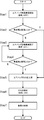
- FIG. 4 is a diagram showing an exhaust gas flow of the airbag.
- the gas exhaust flow shown in FIG. 4 can be implemented.
- Such an exhaust flow starts when a vehicle collision is detected or predicted.
- the pressure of the exhaust port 3 is lower than a predetermined pressure, so that the exhaust nozzle portion 34 is maintained in a bent state and the exhaust of gas is suppressed (exhaust) : OFF).
- exhaust exhaust
- Step 2 there is a case where the airbag 1 is in contact with an occupant or an in-vehicle structure until the airbag 1 is completely inflated and deployed.
- Step 5 When the airbag 1 comes into contact with an occupant or the like (Y), the internal pressure of the airbag 1 increases (Step 5). When the internal pressure of the airbag 1 rises and the pressure of the exhaust port 3 becomes higher than a predetermined pressure, the exhaust nozzle portion 34 stands and the gas is exhausted (Step 6). Then, the occupant is restrained by the airbag 1 (Step 7).
- Step 3 when there is no contact with an occupant or the like during the inflation and deployment (Step 2: N), the inflation and deployment of the airbag 1 is completed (Step 3).
- the exhaust port 3 is configured to maintain a state in which the exhaust nozzle portion 34 is bent at a pressure at which the airbag 1 has been inflated and deployed as usual, and suppresses the exhaust of gas (exhaust: OFF) is maintained.
- the airbag 1 normally comes into contact with an occupant or a vehicle interior structure. If the airbag 1 does not come into contact with an occupant or the like at Step 4 (N), the airbag 1 maintains the inflated and deployed state (Step 3).
- Step 5 When the airbag 1 comes into contact with an occupant or the like at Step 4 (Y), the internal pressure of the airbag 1 increases (Step 5). When the internal pressure of the airbag 1 rises and the pressure of the exhaust port 3 becomes higher than a predetermined pressure, the exhaust nozzle portion 34 stands and the gas is exhausted (Step 6). Then, the occupant is restrained by the airbag 1 (Step 7).
- FIG. 5 is a figure which shows the other method which makes an exhaust port bend easily, (A) is a 1st modification, (B) is a 2nd modification, (C) is a 3rd modification. Show.
- Each drawing shown in FIG. 5 shows only a top view corresponding to FIG.
- FIG. 6 is a diagram showing another structure of the exhaust port, where (A) is a fourth modification, (B) is a fifth modification, (C) is a sixth modification, and (D) is a fifth modification. 7 shows modified examples.
- the first panel 31 and the second panel 32 are made of the same material woven fabric.
- the texture of the panel 32 is sparsely configured.
- the exhaust port 3 can be easily folded toward the second panel 32 disposed inside the folding direction.
- the latter generally has higher elongation when the first panel 31 and the second panel 32 are pulled in the direction of the weave and when pulled in the direction intersecting the weave. Therefore, the first panel 31 may be arranged so as to be pulled in the direction of the texture, and the second panel 32 may be arranged so as to be pulled in the direction intersecting with the texture.
- the first panel 31 and the second panel 32 are made of different materials. That is, the material constituting the second panel 32 is composed of a material having lower rigidity or higher elongation than the material constituting the first panel 31.
- the first panel 31 can be made of the same base fabric as the airbag 1 and the second panel can be made of a material having lower rigidity or higher elongation than the base fabric such as silicon rubber.
- only the first panel 31 may be coated with silicon resin to increase the rigidity.
- the exhaust port 3 can be easily folded toward the second panel 32 disposed inside the folding direction.
- the fourth modification shown in FIG. 6 (A) is configured such that the portions of the first panel 31 and the second panel 32 excluding the surplus portion 35 are substantially rectangular. That is, the surplus portion 36 is left on the outer periphery of the substantially conical curved surface portion 33 and the exhaust nozzle portion 34. With this configuration, it is not necessary to cut the first panel 31 and the second panel 32 along the shapes of the substantially conical curved surface portion 33 and the exhaust nozzle portion 34, and the exhaust port 3 is formed only by sewing the surplus portion 36. Can do. In addition, the stitching
- the fifth modification shown in FIG. 6 (B) is configured such that the overall outer shape of the first panel 31 and the second panel 32 is substantially rectangular. That is, it has a shape in which the convex portion 31R of the first panel 31 and the convex portion 32L of the second panel 32 shown in FIG. Even with such a shape, the surplus portion 35 can be joined to the base fabric 11 of the airbag 1.
- a guide portion 37 that connects the exhaust nozzle portion 34 of the exhaust port 3 and the base fabric 11 is disposed.
- the guide part 37 is a string member made of the same material as the base fabric 11, the first panel 31, or the second panel 32, for example.
- the length of the guide portion 37 is set to a length that does not hinder the exhaust of gas from the exhaust nozzle portion 34 when the substantially conical curved surface portion 33 reaches a predetermined pressure.
- the guide portion 37 is arranged so that the gas is not exhausted to the first panel 31 side than the exhaust nozzle portion 34 is standing.
- One end of the guide portion 37 is connected to the exhaust nozzle portion 34 side of the second panel 32, and the other end is connected to the other member 38.
- the other member 38 includes a vehicle interior structure such as a steering wheel, a retainer that accommodates the airbag 1, a base fabric 11 of the airbag 1 that constitutes a wall surface substantially orthogonal to the base fabric 11 provided with the exhaust port 3, and the like. means.
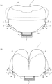
- FIG. 7 is a figure which shows the airbag apparatus for driver's seats which concerns on this invention
- (A) is a rear view
- (B) has shown sectional drawing.
- symbol is attached
- the airbag apparatus shown in FIGS. 7A and 7B includes a gas generator 5 that generates gas under predetermined conditions, an airbag 1 that is connected to the gas generator 5 and inflated and deployed, and an airbag. 1, and the airbag 1 has the exhaust port 3 described above.
- the airbag apparatus shown in FIGS. 7A and 7B is a so-called driver's seat airbag apparatus. Therefore, the airbag 1 has a substantially spherical shape or a substantially elliptic rotating body shape, and the gas generator 5 is connected to the substantially central portion thereof, and is folded and accommodated in the retainer 6. Built in. As shown in FIG.
- the airbag 1 is formed by stitching a front panel 12 disposed on the occupant side and a rear panel 13 disposed on the steering side, and exhausts air to the rear panel 13 side.
- a plurality of mouths 3 are arranged.
- the number of the exhaust ports 3 arranged is set according to the capacity of the airbag 1 or the like, and may be one or two or more.
- the three exhaust ports 3 are equally arranged.
- the exhaust port 3 is installed so that it may fold toward the substantially center part of the airbag 1, and the 2nd panel side is arrange
- the exhaust port 3 is opened, and the gas is exhausted from the exhaust nozzle portion 34. As shown in FIG.
- FIG. 8 is a cross-sectional view showing the passenger seat airbag device, in which (A) shows a normal airbag and (B) shows a twin airbag.
- FIG. 9 is a side view showing another airbag device, in which (A) shows a side airbag and (B) shows a curtain airbag.
- symbol is attached
- the passenger seat airbag apparatus shown in FIGS. 8A and 8B is similar to the driver seat airbag apparatus shown in FIG. 7 in that a gas generator 5 that generates gas under predetermined conditions, and a gas
- the airbag 1 is connected to the generator 5 and inflated and deployed, and the retainer 6 that accommodates the airbag 1, and the airbag 1 has the exhaust port 3 described above.
- the airbag 1 of the passenger seat airbag device is folded and accommodated in a retainer 6 and is built in an instrument panel disposed on the front surface of the passenger.
- the airbag 1 of the passenger seat airbag apparatus has a larger capacity than the airbag 1 of the driver airbag apparatus, and has, for example, a substantially triangular prism shape because the clearance between the passenger and the instrument panel is large. ing.
- the exhaust port 3 is disposed on both side surfaces of the airbag 1. Of course, you may make it arrange
- FIG. 8 (B) a twin airbag having two inflated and deployed portions of a right chamber 14 and a left chamber 15 has been developed. Even when the airbag 1 is a twin airbag, the exhaust ports 3 can be arranged on both side surfaces and the back surface of the airbag 1.
- the side airbag device shown in FIG. 9 (A) is connected to the gas generator 5 for generating gas under a predetermined condition and the gas generator 5, similarly to the driver airbag device shown in FIG. 7.
- the airbag 1 is inflated and deployed, and the retainer 6 that accommodates the airbag 1.
- the airbag 1 has the exhaust port 3 described above.
- the airbag 1 of the side airbag apparatus is folded and accommodated in the retainer 6 and is built in the backrest portion 71 of the vehicle seat 7. Further, the airbag 1 has an inner surface that contacts the occupant and an outer surface 16 on the opposite side, and the exhaust port 3 is disposed on the outer surface 16.
- the curtain airbag device shown in FIG. 9B is connected to the gas generator 5 that generates gas under a predetermined condition and the gas generator 5, similarly to the driver airbag device shown in FIG. 7.
- the airbag 1 is inflated and deployed, and the retainer 6 that accommodates the airbag 1.
- the airbag 1 has the exhaust port 3 described above.
- the airbag 1 of the curtain airbag device is folded and accommodated in a retainer 6 and is built in a side portion 8 of the roof lining.
- a vehicle has pillars such as an A pillar 91, a B pillar 92, and a C pillar 93 that serve as pillars for supporting roof flying.
- the airbag 1 includes a front portion 18 that covers between the A pillar 91 and the B pillar 92, and a rear portion 19 that covers between the B pillar 92 and the C pillar 93.
- the airbag 1 preferably has an inner surface 17 that contacts the occupant and an outer surface that is disposed on the window side, and the exhaust port 3 is preferably disposed on the inner surface 17. This is because when the exhaust port 3 is arranged on the outer side surface, the exhaust port 3 is sandwiched between the airbag 1 and the window, and the gas may not be exhausted. Further, in the airbag 1 shown in FIG.
- the exhaust ports 3 are arranged on the A pillar 91 side of the front portion 18 and the C pillar 93 side of the rear portion 19, and each exhaust port 3 is away from the occupant.
- the exhaust port 3 of the front part 18 is configured to be easily bent toward the A pillar 91 side
- the exhaust port 3 of the rear part 19 is configured to be easily bent toward the C pillar 93 side.
- the present invention is not limited to the above-described embodiment, and a normal vent hole may be formed in the airbag 1 in addition to the exhaust port 3, in addition to the above-described airbag device, a knee airbag device or a pedestrian air
- a normal vent hole may be formed in the airbag 1 in addition to the exhaust port 3, in addition to the above-described airbag device, a knee airbag device or a pedestrian air
- various modifications are possible without departing from the spirit of the present invention, such as the airbag 1 of the present invention being applicable to a bag device.
Landscapes
- Engineering & Computer Science (AREA)
- Mechanical Engineering (AREA)
- Air Bags (AREA)
Abstract
【課題】エアバッグへの組み付けが容易でエアバッグの内圧に応じてガスを排気可能なエアバッグ及びエアバッグ装置を提供する。 【解決手段】本発明のエアバッグ1は、エアバッグ1に形成された開口部2と、開口部2に接続された筒状の排気口3と、を有し、排気口3は所定の方向に折れ易く構成されている。具体的には、前記排気口3は、折れ方向の外側に配置される第一パネル31と、折れ方向の内側に配置される第二パネル32と、を有し、第一パネル31は第二パネル32よりも厚く形成されている。
Description
本発明は、自動車等の車両に搭載されるエアバッグ及びエアバッグ装置に関し、特に、エアバッグのベントホールの開閉手段に特徴を有するエアバッグ及びエアバッグ装置に関する。
自動車等の車両には、衝突時や急減速時等にエアバッグを車内で膨張展開させて乗員に生ずる衝撃を吸収するためのエアバッグ装置が搭載されているのが一般的になってきている。かかるエアバッグ装置には、ステアリングに内装された運転席用エアバッグ装置、インストルメントパネルに内装された助手席用エアバッグ装置、車両側面部又はシートに内装されたサイドエアバッグ装置、ドア上部に内装されたカーテンエアバッグ装置、乗員の膝部に対応したニーエアバッグ装置、フード下に内装された歩行者用エアバッグ装置等、種々のタイプが開発・採用されている。これらのエアバッグ装置は、一般に、所定の条件でガスを発生させるガス発生器と、ガス発生器に接続されて膨張展開するエアバッグと、エアバッグを収容するリテーナと、を備えている。また、エアバッグを形成する外殻には、ベントホールと呼ばれる排気口が形成されている場合もある。このベントホールは、エアバッグの内圧が高くなり過ぎないようにしたり、乗員がエアバッグに接触した際にエアバッグ内のガスを排気して衝撃を緩和したりする機能を有する。
かかるベントホールが形成されたエアバッグ装置では、エアバッグの膨張展開中にベントホールからガスが排気されてしまうため圧力損失が大きいという問題があった。かかる問題点を解決するためのエアバッグ装置には、例えば、特許文献1や特許文献2に記載されたものが既に提案されている。
特許文献1に記載されたエアバッグは、エアバッグの生地(織物)の一部で作られたチューブを有する。該チューブは、エアバッグの内部へ潜りこんでいて、その先端がクランプにより保持されている。この潜り込んだ先端は、クランプによる保持が解除されるとエアバッグ本体から外部へ飛び出すことができるように構成されている。
また、特許文献2に記載されたエアバッグ装置も、特許文献1に記載されたエアバッグと同様に、エアバッグの外殻に接続された排気用チューブを有する(例えば、FIG.11A,11B)。該排気用チューブは、ストラップによりエアバッグの内側に引っ張られており、ストラップを固定するアンカーを解除すると排気用チューブがエアバッグの外側に開放されてベントホールとして作用するようになっている。
上述した特許文献1や特許文献2に記載されたエアバッグでは、エアバッグの内部に引き込まれたチューブ状の排気口をベントホールに形成することにより、チューブがエアバッグの外部に放出されるまではガスの排気を抑制することができる。
しかしながら、(1)チューブの先端をエアバッグ内で保持する保持機構(クランプやアンカー)が必要であり組み付けが困難である、(2)保持機構が解除されてからチューブが外部に放出されるまでの時間を要するためエアバッグの内圧が高くなり過ぎてしまう、(3)エアバッグの変形やガス圧によるエアバッグ内面への押し付け等によりチューブが外部に放出し難い場合がある、等の問題がある。特に、前記(3)の問題では、ベントホールとして機能しなかったり、前記(2)の問題がより顕著になったりしてしまう。
本発明は上述した問題点に鑑み創案されたものであり、エアバッグへの組み付けが容易でエアバッグの内圧に応じてガスを排気可能なエアバッグ及びエアバッグ装置を提供することを目的とする。
本発明によれば、内部にガスが供給されて膨張展開するエアバッグにおいて、前記エアバッグに形成された開口部と、該開口部に接続された筒状の排気口と、を有し、前記排気口は所定の方向に折れ易く構成されている、ことを特徴とするエアバッグが提供される。
また、本発明によれば、所定の条件でガスを発生させるガス発生器と、該ガス発生器に接続されて膨張展開されるエアバッグと、該エアバッグを収容するリテーナと、を備えたエアバッグ装置において、前記エアバッグは、前記エアバッグに形成された開口部と、該開口部に接続された筒状の排気口と、を有し、前記排気口は所定の方向に折れ易くなるように構成されている、ことを特徴とするエアバッグ装置が提供される。
上述したエアバッグ又はエアバッグ装置において、前記排気口は、折れ方向の外側に配置される第一パネルと、折れ方向の内側に配置される第二パネルと、を有し、前記第二パネルは前記第一パネルよりも剛性が低い素材により構成されていてもよいし、前記第一パネルは前記第二パネルよりも厚く形成されていてもよいし、前記第二パネルは前記第一パネルよりも伸度が高くなるように形成されていてもよい。
上述したエアバッグ又はエアバッグ装置において、前記排気口は、前記開口部から徐々に縮径した略円錐曲面部と、該略円錐曲面部の最小径以上の径を有する排気ノズル部と、を有し、前記略円錐曲面部を構成する円錐の頂点が前記排気ノズル部内に位置するように設定されていることが好ましい。例えば、前記略円錐曲面部の上端から前記頂点までの距離は、前記排気ノズル部の長さの半分以下に設定される。また、前記排気ノズル部は、先端部に向かって徐々に拡径するように形成されていてもよい。さらに、前記排気ノズル部は、折れ方向の内側に位置する前記エアバッグに接続されるガイド部を有し、ガスの排気状態において前記排気ノズル部が折れ易い側に傾斜した状態を維持するように構成されていてもよい。
上述したエアバッグ又はエアバッグ装置において、前記排気口は、折れ方向の外側に配置される第一パネルと、折れ方向の内側に配置される第二パネルと、を有し、前記第一パネル及び前記第二パネルは、組み合わせた時に略山字状となるように形成されており、互いの両端部どうしを重ねた状態で前記開口部に縫合されるようにしてもよい。また、上述したエアバッグ装置において、前記エアバッグの排気口が、前記エアバッグの外部で折れ易い方向に折り畳まれて前記リテーナに収容されていることが好ましい。
上述した本発明に係るエアバッグ及びエアバッグ装置によれば、所定の方向に折れ易く構成された排気口を設けたことにより、排気口に所定の圧力が負荷されるまでは排気口を折れ曲がった状態に維持することができ、エアバッグ内のガスの排気を抑制することができる。また、排気口をエアバッグの外部で折り畳むことにより、排気口に所定の圧力が負荷された場合に、排気口の折れ曲がり部が直ちに立ち上がり、迅速にガスを排気することができる。
また、前記排気口を構成するパネルの一方を剛性が低い素材により構成したり、厚く形成したり、伸度が高くなるように形成したりすることにより、容易に所定の方向に折れ易く構成された排気口を形成することができる。特に、剛性が低い素材や伸度が高くなるように構成されたパネルは、他方のパネルよりもガスの圧力を受け易く、他方のパネルを折れ曲がる方向に引き付けて、ガスの排気を抑制し易くすることができる。
また、前記排気口を略円錐曲面部と排気ノズル部とから構成することにより、略円錐曲面部の頂点付近で排気口を折れ曲がり易くすることができ、ガスの排気を抑制し易くすることができる。特に、略円錐曲面部の上端から頂点までの距離を排気ノズル部の長さの半分以下に設定することにより、折れ曲がり易い排気口を容易に形成することができる。また、排気ノズル部を先端部に向かって徐々に拡径させることにより、排気口にスロート部を構成することができ、継ぎ目付近で折れ曲がり易くすることができるとともに、所定の圧力が達した場合にガスを容易に排気させることができる。また、排気ノズル部にガイド部を設けることにより、ガスの排気中における排気口の位置やガスの排気方向を安定させることができる。さらに、排気口を構成するパネルを略山字状に形成することにより、圧力が負荷され易い排気口の接続部を補強してガスの漏洩を抑制することができる。
以下、本発明の実施形態について図1~図9を用いて説明する。ここで、図1は、本発明に係るエアバッグの排気機構部を示す図であり、(A)はロック状態、(B)は排気状態、を示している。また、図2は、排気口の構成図であり、(A)は正面図、(B)は上面図、(C)は接続状態における上面図、を示している。
図1(A)及び(B)に示した本発明のエアバッグ1は、エアバッグ1に形成された開口部2と、開口部2に接続された筒状の排気口3と、を有し、排気口3は所定の方向に折れ易く構成されている。具体的には、前記排気口3は、折れ方向の外側に配置される第一パネル31と、折れ方向の内側に配置される第二パネル32と、を有し、第一パネル31は第二パネル32よりも厚く形成されている。また、排気口3は、開口部2から徐々に縮径した略円錐曲面部33と、略円錐曲面部33の最小径Rn以上の径を有する排気ノズル部34と、を有し、略円錐曲面部33を構成する円錐の頂点Pが排気ノズル部34内に位置するように設定されている。
前記開口部2は、エアバッグ1の外殻を構成する基布11に形成されたスリット状又はスロット状をなしている。エアバッグ1が膨張展開する前までは、この開口部2は閉じた状態を維持している。そして、図1(A)に示すように、排気口3にエアバッグ1内のガスが流入して略円錐曲面部33が略円錐状に膨張展開すると、開口部2は排気口3の形状に合わせて、例えば、略円形状に開いた状態となる。
前記排気口3は、例えば、図2に示した構成をなしている。図2に示した排気口3は、折れ方向の外側に配置される第一パネル31と、折れ方向の内側に配置される第二パネル32と、を有し、第一パネル31と第二パネル32とは同じ素材の織布(例えば、ナイロン糸の織布に樹脂コーティングを施したもの)により構成されるとともに、第一パネル31は第二パネル32よりも厚く形成されている。図2(B)に示したように、第一パネル31及び第二パネル32は、第一パネル31の厚さをt1とし、第二パネル32の厚さをt2とすれば、厚さt1>厚さt2となるように形成される。第一パネル31と第二パネル32の厚さt1,t2は、ナイロン糸の織り方やナイロン糸の太さを変更することにより調整される。このように同じ素材の織布から構成される第一パネル31と第二パネル32の厚さt1,t2を調整することにより、折れ方向の外側に配置される第一パネル31よりも折れ方向の内側に配置される第二パネル32の剛性が低く、伸度が高くなるように設定することができる。したがって、第一パネル31よりも第二パネル32を柔らかく形成することができ、第二パネル32の側に折れ易い排気口3を形成することができる。
図2(A)に示したように、第一パネル31及び第二パネル32は、略円錐曲面部33と、排気ノズル部34と、エアバッグ1の開口部2との接合部を構成する余肉部35(図の斜線部)と、を有する。ここで、略円錐曲面部33の母線と中心線Lとのなす角度をαとし、排気ノズル部34の母線と中心線L(の平行線)とのなす角度をβとし、略円錐曲面部33の下底部の半径をRd、排気ノズル部34の上底部の半径をRu、排気口3の最小径をRn、略円錐曲面部33の高さをHc、略円錐曲面部33の頂点Pの高さ(略円錐曲面部33の上端から頂点Pまでの距離)をHp、排気ノズル部34の高さ(長さ)をHnとする。これらの数値は、エアバッグ1の容量、開口部2の大きさ、排気口3の設置数等の条件に基づいて、排気口3の内部が所定の圧力に達した場合に排気ノズル部34が起立してガスを排気できるように、シミュレーションや実験を繰り返して調整される。また、エアバッグ1に乗員や車内構造物が接触する前のエアバッグ1の膨張展開中において、ガスの圧力変動により排気ノズル部34が起立しないように、頂点Pの高さHpを排気ノズル部34の高さHnの半分以下、好ましくは、1/3~1/2の範囲となるように設定することが好ましい。また、排気ノズル部34は、排気時におけるガスの流れを阻害しないように、半径Ru≧半径Rn又は角度β≧0°となるように設定し、先端部に向かって徐々に拡径するように形成することが好ましい。また、半径Rdが120~130mm程度の場合に、角度αを30°前後に設定すると効果的である。
また、図2(A)に示したように、第一パネル31及び第二パネル32は、両パネルを組み合わせた時に略山字状をなすように形成されており、図の斜線部で示した部分が余肉部35を構成している。この余肉部35は、エアバッグ1の基布11に縫合される部分である。また、山字状の左右両端部は、それぞれ第一パネル31の凸部31Rと、第二パネル32の凸部32Lとにより構成されている。かかる凸部31R,32Lは、図2(C)に示すように、縫合時には他方の余肉部35と重なり合うラップ部w(図の斜線部)を形成し、接合部を補強する機能を有する。排気口3のエアバッグ1への接合時には、図2(C)に示すように、第一パネル31及び第二パネル32の排気ノズル部34及び略円錐曲面部33を、一点鎖線で示すエアバッグ1の開口部2に通した後、余肉部35を広げてエアバッグ1の基布11に縫合する。
かかる構成の排気口3をエアバッグ1の開口部2に接続することにより、図1(A)に示すように、所定の方向(第二パネル32側)に折れ易い構造の排気機構部を形成することができる。したがって、排気口3に所定の圧力が負荷されるまでは排気口3を折れ曲がった状態に維持することができ、エアバッグ1内のガスの排気を抑制することができる。なお、排気口3の折れ方向は、例えば、乗員から遠ざかる方向やエアバッグの略中央部方向に設定されるが、これらに限定されるものではない。
ここで、図3は、本発明に係るエアバッグの作用を示す図であり、(A)は膨張展開前、(B)は膨張展開中(圧力小)、(C)は膨張展開中(圧力大)、(D)はガス排気状態、を示している。
図3(A)に示すように、排気口3は、エアバッグ1の基布11に余肉部35により接続されており、エアバッグ1の外部で折れ易い方向(第二パネル32側)に折り畳まれて図示しないリテーナに収容されている。このように折れ易い方向に折り畳んでおくことにより、排気口3に折れ癖をつけることができる。また、図示しないが、略円錐曲面部33と基布11の間に排気ノズル部34を挟み込むように排気口3を折り畳むようにしてもよい。そして、エアバッグ1の膨張展開前は、図3(A)に示すように、開口部2は閉じた状態を維持している。
図3(B)に示すように、エアバッグ1が膨張展開を開始すると、徐々に開口部2も開き始め、排気口3の略円錐曲面部33にガスが流入する。略円錐曲面部33のガスの圧力が小さい場合には、排気口3は頂点Pで折れ曲がった状態を維持し、排気ノズル部34はロックされた状態となり、ガスを排気しないようにする。したがって、膨張展開中における無駄なガスの排気を抑制することができ、インフレータの小型化を図ることができる。
図3(C)に示すように、エアバッグ1の膨張展開が進行すると、略円錐曲面部33内のガスの圧力が大きくなり、略円錐曲面部33は第二パネル32側に膨らんだ形状に変形する。これは、第一パネル31よりも第二パネル32の方が、剛性が低く、伸度が高いためである。その結果、頂点Pは第二パネル32側に引き寄せられ、排気ノズル部34は折れ曲がった状態を維持して締め付けられ、効果的にガスの排気を抑制することができる。
図3(D)に示すように、乗員がエアバッグ1に接触すると、エアバッグ1内の圧力は急激に上昇し、排気口3の略円錐曲面部33内のガスの圧力が所定の圧力に達すると、排気ノズル部34は折れ曲がった状態から起立して排気口3が開放され、ガスが排気される。かかるガスの排気によって、乗員をエアバッグ1で効果的に拘束することができる。また、図示しないが、排気口3の略円錐曲面部33内のガスの圧力が所定の圧力よりも小さくなると、排気ノズル部34は再び第二パネル32側に折れ曲がり、排気口3はガスの排気を抑制する。
ここで、図4は、エアバッグのガスの排気フローを示す図である。図3に示したエアバッグ1の作用によれば、図4に示したガスの排気フローを実施することができる。かかる排気フローは、車両の衝突を検知又は予知した場合にスタートする。エアバッグ1の膨張展開が開始した状態(Step1)では、排気口3の圧力は所定の圧力よりも低いため排気ノズル部34は折れ曲がった状態を維持し、ガスの排気を抑制している(排気:OFF)。また、エアバッグ1が膨張展開を完了するまでの間に、乗員や車内構造物と接触する場合もある(Step2)。エアバッグ1が乗員等と接触した場合(Y)には、エアバッグ1の内圧が上昇する(Step5)。エアバッグ1の内圧が上昇し、排気口3の圧力が所定の圧力よりも高くなると、排気ノズル部34が起立してガスが排気される(Step6)。そして、乗員はエアバッグ1により拘束される(Step7)。
また、膨張展開中に乗員等との接触がない場合(Step2:N)には、エアバッグ1の膨張展開が完了する(Step3)。排気口3は、エアバッグ1が通常どおりに膨張展開が完了した程度の圧力では、排気ノズル部34が折れ曲がった状態を維持するように構成されており、ガスの排気を抑制した状態(排気:OFF)を維持する。エアバッグ1の膨張展開が完了すると、通常、エアバッグ1は乗員や車内構造物と接触することとなる。Step4で、エアバッグ1が乗員等と接触しない場合(N)には、エアバッグ1は膨張展開した状態(Step3)を維持する。そして、Step4で、エアバッグ1が乗員等と接触した場合(Y)には、エアバッグ1の内圧が上昇する(Step5)。エアバッグ1の内圧が上昇し、排気口3の圧力が所定の圧力よりも高くなると、排気ノズル部34が起立してガスが排気される(Step6)。そして、乗員はエアバッグ1により拘束される(Step7)。
次に、本発明に係るエアバッグ1の変形例について説明する。ここで、図5は、排気口を折れ易くする他の方法を示す図であり、(A)は第一変形例、(B)は第二変形例、(C)は第三変形例、を示している。なお、図5に示した各図は、図2(B)に相当する上面図のみを図示したものである。また、図6は、排気口の他の構造を示す図であり、(A)は第四変形例、(B)は第五変形例、(C)は第六変形例、(D)は第七変形例、を示している。
図5(A)に示した第一変形例は、第一パネル31と第二パネル32とは同じ素材の織布により構成されているが、第一パネル31の織布を二重に配置したものである。すなわち、第一パネル31の厚さt1は、第二パネル32の厚さt2(=t)の2倍(2t)に形成されている。かかる構成によっても、排気口3を折れ方向の内側に配置される第二パネル32側に折れ易くすることができる。
図5(B)に示した第二変形例は、第一パネル31と第二パネル32とは同じ素材の織布により構成されているが、第一パネル31の織目を蜜にし、第二パネル32の織目を疎に構成したものである。このように同じ素材であっても織目の疎密を軽重させることにより、第一パネル31及び第二パネル32の伸度を調整することができる。かかる構成によっても、排気口3を折れ方向の内側に配置される第二パネル32側に折れ易くすることができる。また、第一パネル31及び第二パネル32を織目の方向に引っ張る場合と、織目と交差する方向に引っ張る場合とでは、後者の方が一般に伸度が高い。そこで、第一パネル31を織目の方向に引っ張られるように配置し、第二パネル32を織目と交差する方向に引っ張られるように配置するようにしてもよい。
図5(C)に示した第三変形例は、第一パネル31と第二パネル32とを異なる素材により構成したものである。すなわち、第二パネル32を構成する素材は、第一パネル31を構成する素材よりも剛性が低い又は伸度が高い素材により構成される。例えば、第一パネル31をエアバッグ1と同じ基布により構成し、第二パネルをシリコンゴム等の基布よりも剛性が低いか伸度が高い素材により構成することができる。また、第一パネル31及び第二パネル32の剛性や伸度は、コーティングの有無やコーティングの厚さによって調節するようにしてもよい。例えば、第一パネル31のみシリコン樹脂によりコーティングして剛性を高くするようにしてもよい。これらの構成によっても、排気口3を折れ方向の内側に配置される第二パネル32側に折れ易くすることができる。
図6(A)に示した第四変形例は、第一パネル31及び第二パネル32の余肉部35を除いた部分が略長方形となるように構成したものである。すなわち、略円錐曲面部33及び排気ノズル部34の外周に余肉部36を残したものである。かかる構成により、第一パネル31及び第二パネル32を略円錐曲面部33及び排気ノズル部34の形状に沿って切り取る必要がなく、余肉部36を縫合するだけで排気口3を形成することができる。なお、縫合部は点線により図示している。
図6(B)に示した第五変形例は、第一パネル31及び第二パネル32の全体の外形が略長方形となるように構成したものである。すなわち、図2(A)に示した第一パネル31の凸部31Rと、第二パネル32の凸部32Lを切り落とした形状をなしている。かかる形状によっても、余肉部35によりエアバッグ1の基布11に接合することができる。
図6(C)に示した第六変形例は、排気口3の排気ノズル部34と基布11とを連結するガイド部37を配置したものである。かかるガイド部37を配置することにより、排気口3からガスを排気する方向を一定の方向に保持することができる。ガイド部37は、例えば、基布11や第一パネル31又は第二パネル32と同じ素材により構成される紐部材である。ガイド部37の長さは、略円錐曲面部33が所定の圧力に達した際に、排気ノズル部34からのガスの排気を阻害しない長さに設定される。
図6(D)に示した第七変形例は、ガイド部37を排気ノズル部34が起立した状態よりも第一パネル31側にガスが排気されないように配置したものである。ガイド部37の一端は第二パネル32の排気ノズル部34側に接続され、他端は他部材38に接続される。ここで、他部材38とは、ステアリング等の車内構造物、エアバッグ1を収容するリテーナ、排気口3を設置した基布11と略直交する壁面を構成するエアバッグ1の基布11等を意味する。
続いて、本発明に係るエアバッグ装置について説明する。ここで、図7は、本発明に係る運転席用エアバッグ装置を示す図であり、(A)は背面図、(B)は断面図、を示している。なお、図1に示したエアバッグ1と同じ構成部品については同じ符号を付し、重複した説明を省略する。
図7(A)及び(B)に示したエアバッグ装置は、所定の条件でガスを発生させるガス発生器5と、ガス発生器5に接続されて膨張展開されるエアバッグ1と、エアバッグ1を収容するリテーナ6と、を備え、エアバッグ1は上述した排気口3を有する。図7(A)及び(B)に示したエアバッグ装置は、いわゆる運転席用エアバッグ装置である。したがって、エアバッグ1は略球形状又は略楕円回転体形状をなしており、その略中央部にガス発生器5が接続されており、リテーナ6内に折り畳まれて収容され、ステアリングの中央部に内蔵される。図7(B)に示すように、エアバッグ1は、乗員側に配置されるフロントパネル12と、ステアリング側に配置されるリアパネル13と、を縫合して形成されており、リアパネル13側に排気口3が複数配置されている。配置される排気口3の個数は、エアバッグ1の容量等により設定され、1個でもよいし2個以上であってもよい。ここでは3個の排気口3を均等に配置している。また、排気口3は、エアバッグ1の略中央部に向かって折れるように設置され、第二パネル側を折れ方向内側、第一パネル31を折れ方向外側に配置している。そして、図7(B)において一点鎖線で示すように、エアバッグ1の内圧が所定の圧力になると排気口3は開放され、排気ノズル部34からガスを排気する。
次に、本発明に係る他のエアバッグ装置について説明する。ここで、図8は、助手席用エアバッグ装置を示す断面図であり、(A)は通常のエアバッグ、(B)はツインエアバッグ、を示している。また、図9は、他のエアバッグ装置を示す側面図であり、(A)はサイドエアバッグ、(B)はカーテンエアバッグ、を示している。なお、図7に示したエアバッグ装置と同じ構成部品については同じ符号を付し、重複した説明を省略する。
図8(A)及び(B)に示した助手席用エアバッグ装置は、図7に示した運転席用エアバッグ装置と同様に、所定の条件でガスを発生させるガス発生器5と、ガス発生器5に接続されて膨張展開されるエアバッグ1と、エアバッグ1を収容するリテーナ6と、を備え、エアバッグ1は上述した排気口3を有する。助手席用エアバッグ装置のエアバッグ1は、リテーナ6内に折り畳まれて収容され、乗員の前面に配置されたインストルメントパネルに内蔵される。また、助手席用エアバッグ装置のエアバッグ1は、乗員とインストルメントパネルとの隙間が大きいため、運転席用エアバッグ装置のエアバッグ1よりも一般に容量が大きく、例えば、略三角柱形状をなしている。排気口3は、エアバッグ1の両側面部に配置される。勿論、排気口3は、側面部に替えて乗員から最も離れた背面部に配置するようにしてもよい。また、近年では、図8(B)に示したように、右室14と左室15の2室の膨張展開部を備えたツインエアバッグも開発されている。エアバッグ1がツインエアバッグの場合であっても、エアバッグ1の両側面部や背面部に排気口3を配置することができる。
図9(A)に示したサイドエアバッグ装置は、図7に示した運転席用エアバッグ装置と同様に、所定の条件でガスを発生させるガス発生器5と、ガス発生器5に接続されて膨張展開されるエアバッグ1と、エアバッグ1を収容するリテーナ6と、を備え、エアバッグ1は上述した排気口3を有する。サイドエアバッグ装置のエアバッグ1は、リテーナ6内に折り畳まれて収容され、車両シート7の背もたれ部71に内蔵される。また、かかるエアバッグ1は、乗員に接触する内側面と反対側の外側面16とを有し、排気口3は外側面16に配置される。
図9(B)に示したカーテンエアバッグ装置は、図7に示した運転席用エアバッグ装置と同様に、所定の条件でガスを発生させるガス発生器5と、ガス発生器5に接続されて膨張展開されるエアバッグ1と、エアバッグ1を収容するリテーナ6と、を備え、エアバッグ1は上述した排気口3を有する。カーテンエアバッグ装置のエアバッグ1は、リテーナ6内に折り畳まれて収容され、ルーフライニングのサイド部8に内蔵される。一般に車両は、ルーフライニングを支える柱となるAピラー91、Bピラー92、Cピラー93等のピラーを有している。そして、エアバッグ1は、Aピラー91とBピラー92の間を覆うフロント部18と、Bピラー92とCピラー93の間を覆うリア部19と、を有している。また、かかるエアバッグ1は、乗員に接触する内側面17と窓側に配置される外側面とを有し、排気口3は内側面17に配置することが好ましい。外側面に排気口3を配置した場合には、エアバッグ1と窓の間に排気口3が挟まれてしまい、ガスを排気することができなってしまう場合があるためである。また、図9(B)に示したエアバッグ1では、フロント部18のAピラー91側とリア部19のCピラー93側に排気口3が配置されており、各排気口3は乗員から遠ざかる方向、すなわち、フロント部18の排気口3はAピラー91側に、リア部19の排気口3はCピラー93側に、それぞれ折れ易くなるように構成されている。
本発明は上述した実施形態に限定されず、排気口3に加えて通常のベントホールをエアバッグ1に形成してもよい、上述したエアバッグ装置の他にニーエアバッグ装置や歩行者用エアバッグ装置に本発明のエアバッグ1を適用してもよい等、本発明の趣旨を逸脱しない範囲で種々変更が可能であることは勿論である。
Claims (11)
- 内部にガスが供給されて膨張展開するエアバッグにおいて、前記エアバッグに形成された開口部と、該開口部に接続された筒状の排気口と、を有し、前記排気口は所定の方向に折れ易く構成されている、ことを特徴とするエアバッグ。
- 前記排気口は、折れ方向の外側に配置される第一パネルと、折れ方向の内側に配置される第二パネルと、を有し、前記第二パネルは前記第一パネルよりも剛性が低い素材により構成されている、ことを特徴とする請求項1に記載のエアバッグ。
- 前記排気口は、折れ方向の外側に配置される第一パネルと、折れ方向の内側に配置される第二パネルと、を有し、前記第一パネルは前記第二パネルよりも厚く形成されている、ことを特徴とする請求項1に記載のエアバッグ。
- 前記排気口は、折れ方向の外側に配置される第一パネルと、折れ方向の内側に配置される第二パネルと、を有し、前記第二パネルは前記第一パネルよりも伸度が高くなるように形成されている、ことを特徴とする請求項1に記載のエアバッグ。
- 前記排気口は、前記開口部から徐々に縮径した略円錐曲面部と、該略円錐曲面部の最小径以上の径を有する排気ノズル部と、を有し、前記略円錐曲面部を構成する円錐の頂点が前記排気ノズル部内に位置するように設定されている、ことを特徴とする請求項1に記載のエアバッグ。
- 前記略円錐曲面部の上端から前記頂点までの距離が、前記排気ノズル部の長さの半分以下である、ことを特徴とする請求項5に記載のエアバッグ。
- 前記排気ノズル部は、先端部に向かって徐々に拡径するように形成されている、ことを特徴とする請求項5に記載のエアバッグ。
- 前記排気ノズル部は、折れ方向の内側に位置する前記エアバッグに接続されるガイド部を有し、ガスの排気状態において前記排気ノズル部が折れ易い側に傾斜した状態を維持するように構成されている、ことを特徴とする請求項5に記載のエアバッグ。
- 前記排気口は、折れ方向の外側に配置される第一パネルと、折れ方向の内側に配置される第二パネルと、を有し、前記第一パネル及び前記第二パネルは、組み合わせた時に略山字状となるように形成されており、互いの両端部どうしを重ねた状態で前記開口部に縫合される、ことを特徴とする請求項1に記載のエアバッグ。
- 所定の条件でガスを発生させるガス発生器と、該ガス発生器に接続されて膨張展開されるエアバッグと、該エアバッグを収容するリテーナと、を備えたエアバッグ装置において、前記エアバッグは、請求項1~請求項9のいずれかに記載されたエアバッグである、ことを特徴とするエアバッグ装置。
- 前記エアバッグの排気口が、前記エアバッグの外部で折れ易い方向に折り畳まれて前記リテーナに収容される、ことを特徴とする請求項10に記載のエアバッグ装置。
Applications Claiming Priority (2)
| Application Number | Priority Date | Filing Date | Title |
|---|---|---|---|
| JP2009007291A JP2010163064A (ja) | 2009-01-16 | 2009-01-16 | エアバッグ及びエアバッグ装置 |
| JP2009-007291 | 2009-01-16 |
Publications (1)
| Publication Number | Publication Date |
|---|---|
| WO2010082386A1 true WO2010082386A1 (ja) | 2010-07-22 |
Family
ID=42339649
Family Applications (1)
| Application Number | Title | Priority Date | Filing Date |
|---|---|---|---|
| PCT/JP2009/067745 Ceased WO2010082386A1 (ja) | 2009-01-16 | 2009-10-14 | エアバッグ及びエアバッグ装置 |
Country Status (2)
| Country | Link |
|---|---|
| JP (1) | JP2010163064A (ja) |
| WO (1) | WO2010082386A1 (ja) |
Cited By (2)
| Publication number | Priority date | Publication date | Assignee | Title |
|---|---|---|---|---|
| US10953839B2 (en) | 2018-03-29 | 2021-03-23 | Toyoda Gosei Co., Ltd. | Airbag device having controlled exhaust hole |
| CN116323332A (zh) * | 2020-10-27 | 2023-06-23 | 奥托立夫开发公司 | 乘员保护装置 |
Families Citing this family (1)
| Publication number | Priority date | Publication date | Assignee | Title |
|---|---|---|---|---|
| JP7127444B2 (ja) * | 2018-09-11 | 2022-08-30 | Joyson Safety Systems Japan株式会社 | エアバッグ |
Citations (5)
| Publication number | Priority date | Publication date | Assignee | Title |
|---|---|---|---|---|
| JPH08268213A (ja) * | 1995-03-31 | 1996-10-15 | Honda Motor Co Ltd | エアバッグ装置 |
| JP2000190804A (ja) * | 1998-12-25 | 2000-07-11 | Nippon Plast Co Ltd | 側面衝突用エアバッグ装置 |
| JP2002274307A (ja) * | 2001-03-10 | 2002-09-25 | Daimler Chrysler Ag | 自動車用安全装置 |
| JP2007276535A (ja) * | 2006-04-03 | 2007-10-25 | Toyoda Gosei Co Ltd | 助手席用エアバッグ装置 |
| JP2008308139A (ja) * | 2007-06-18 | 2008-12-25 | Takata Corp | エアバッグ、エアバッグ装置及びエアバッグの排気方法 |
-
2009
- 2009-01-16 JP JP2009007291A patent/JP2010163064A/ja active Pending
- 2009-10-14 WO PCT/JP2009/067745 patent/WO2010082386A1/ja not_active Ceased
Patent Citations (5)
| Publication number | Priority date | Publication date | Assignee | Title |
|---|---|---|---|---|
| JPH08268213A (ja) * | 1995-03-31 | 1996-10-15 | Honda Motor Co Ltd | エアバッグ装置 |
| JP2000190804A (ja) * | 1998-12-25 | 2000-07-11 | Nippon Plast Co Ltd | 側面衝突用エアバッグ装置 |
| JP2002274307A (ja) * | 2001-03-10 | 2002-09-25 | Daimler Chrysler Ag | 自動車用安全装置 |
| JP2007276535A (ja) * | 2006-04-03 | 2007-10-25 | Toyoda Gosei Co Ltd | 助手席用エアバッグ装置 |
| JP2008308139A (ja) * | 2007-06-18 | 2008-12-25 | Takata Corp | エアバッグ、エアバッグ装置及びエアバッグの排気方法 |
Cited By (2)
| Publication number | Priority date | Publication date | Assignee | Title |
|---|---|---|---|---|
| US10953839B2 (en) | 2018-03-29 | 2021-03-23 | Toyoda Gosei Co., Ltd. | Airbag device having controlled exhaust hole |
| CN116323332A (zh) * | 2020-10-27 | 2023-06-23 | 奥托立夫开发公司 | 乘员保护装置 |
Also Published As
| Publication number | Publication date |
|---|---|
| JP2010163064A (ja) | 2010-07-29 |
Similar Documents
| Publication | Publication Date | Title |
|---|---|---|
| JP3782793B2 (ja) | 改良型のカーテンエアバッグ組立体 | |
| JP5808983B2 (ja) | エアバッグ装置 | |
| JP4946858B2 (ja) | 側突用エアバッグ装置 | |
| US7708305B2 (en) | Airbag apparatus | |
| US8864170B2 (en) | Airbag for a front passenger's seat | |
| JP2014208513A (ja) | 歩行者用エアバッグ装置 | |
| JP2007022265A (ja) | 頭部保護エアバッグ装置 | |
| CN101927747B (zh) | 头部保护气囊装置 | |
| JP6871974B2 (ja) | サイドエアバッグ装置 | |
| JP6578910B2 (ja) | 頭部保護エアバッグ装置及び頭部保護エアバッグの折り完了体 | |
| JP2011111092A (ja) | カーテンバッグ | |
| JP6116947B2 (ja) | エアバッグ装置 | |
| JP6177760B2 (ja) | カーテンエアバッグ装置 | |
| WO2010082386A1 (ja) | エアバッグ及びエアバッグ装置 | |
| JP3170705U (ja) | エアバッグ及びエアバッグ装置 | |
| JP5029233B2 (ja) | 頭部保護エアバッグ | |
| JP2006117109A (ja) | エアバッグ装置 | |
| JP2011057028A (ja) | エアバッグ | |
| JP3760211B2 (ja) | エアバッグ | |
| JP2009051446A (ja) | カーテンエアバッグ装置 | |
| JP7209924B2 (ja) | カーテンシールドエアバッグ装置 | |
| JP2005329749A (ja) | 助手席用エアバッグ | |
| JP4820475B2 (ja) | エアバッグの折り畳み方法及びエアバッグ装置の組立て方法、並びにエアバッグ | |
| JP2010089547A (ja) | 頭部保護エアバッグ装置 | |
| JP5344971B2 (ja) | エアバッグ及びエアバッグ装置 |
Legal Events
| Date | Code | Title | Description |
|---|---|---|---|
| 121 | Ep: the epo has been informed by wipo that ep was designated in this application |
Ref document number: 09838353 Country of ref document: EP Kind code of ref document: A1 |
|
| NENP | Non-entry into the national phase |
Ref country code: DE |
|
| 122 | Ep: pct application non-entry in european phase |
Ref document number: 09838353 Country of ref document: EP Kind code of ref document: A1 |