WO2010073340A1 - コードエンドストッパー - Google Patents
コードエンドストッパー Download PDFInfo
- Publication number
- WO2010073340A1 WO2010073340A1 PCT/JP2008/073598 JP2008073598W WO2010073340A1 WO 2010073340 A1 WO2010073340 A1 WO 2010073340A1 JP 2008073598 W JP2008073598 W JP 2008073598W WO 2010073340 A1 WO2010073340 A1 WO 2010073340A1
- Authority
- WO
- WIPO (PCT)
- Prior art keywords
- plug
- string
- socket
- opening
- leg
- Prior art date
- Legal status (The legal status is an assumption and is not a legal conclusion. Google has not performed a legal analysis and makes no representation as to the accuracy of the status listed.)
- Ceased
Links
Images






Classifications
-
- D—TEXTILES; PAPER
- D07—ROPES; CABLES OTHER THAN ELECTRIC
- D07B—ROPES OR CABLES IN GENERAL
- D07B9/00—Binding or sealing ends, e.g. to prevent unravelling
-
- F—MECHANICAL ENGINEERING; LIGHTING; HEATING; WEAPONS; BLASTING
- F16—ENGINEERING ELEMENTS AND UNITS; GENERAL MEASURES FOR PRODUCING AND MAINTAINING EFFECTIVE FUNCTIONING OF MACHINES OR INSTALLATIONS; THERMAL INSULATION IN GENERAL
- F16G—BELTS, CABLES, OR ROPES, PREDOMINANTLY USED FOR DRIVING PURPOSES; CHAINS; FITTINGS PREDOMINANTLY USED THEREFOR
- F16G11/00—Means for fastening cables or ropes to one another or to other objects; Caps or sleeves for fixing on cables or ropes
- F16G11/02—Means for fastening cables or ropes to one another or to other objects; Caps or sleeves for fixing on cables or ropes with parts deformable to grip the cable or cables; Fastening means which engage a sleeve or the like fixed on the cable
- F16G11/025—Fastening means which engage a sleeve or the like fixed on the cable, e.g. caps
-
- F—MECHANICAL ENGINEERING; LIGHTING; HEATING; WEAPONS; BLASTING
- F16—ENGINEERING ELEMENTS AND UNITS; GENERAL MEASURES FOR PRODUCING AND MAINTAINING EFFECTIVE FUNCTIONING OF MACHINES OR INSTALLATIONS; THERMAL INSULATION IN GENERAL
- F16G—BELTS, CABLES, OR ROPES, PREDOMINANTLY USED FOR DRIVING PURPOSES; CHAINS; FITTINGS PREDOMINANTLY USED THEREFOR
- F16G11/00—Means for fastening cables or ropes to one another or to other objects; Caps or sleeves for fixing on cables or ropes
- F16G11/14—Devices or coupling-pieces designed for easy formation of adjustable loops, e.g. choker hooks; Hooks or eyes with integral parts designed to facilitate quick attachment to cables or ropes at any point, e.g. by forming loops
Definitions
- the present invention relates to a cord end stopper attached to the end of a string-like object or a band-like object.
- the string is used for various purposes.
- a string is frequently used for sealing of openings and the like in shoes and bags, clothing and accessories, and adjustment of dimensions and the like.
- strings are used in various situations such as connection of goods and fixing of cargo.
- the string here is a general term for a so-called string-like body that can be bound and includes a general string, a wire, a cable, and the like, as well as a tape and a belt.
- These strings are generally subjected to end processing. In other words, the appearance or feel of the cross section is inferior when it is simply cut, and unraveling may occur in a knitted material.
- the simplest of edge treatment is to tie a knot on the string. However, it is not preferable to make a knot on the string at the manufacturing site, and there is also a demand for improving the decorativeness of the product, and a dedicated cord end stopper is attached to the end of the string.
- a resin molded product that accommodates a string end portion (an area having a predetermined length from the end of the string) is used. Specifically, the half-divided main body is connected by a hinge and the end of the string-like object or band-like object (string end part) is sandwiched, or the end of the string is inserted from one of the cylindrical sockets.
- a type in which a string end is locked with a plug inserted from the opposite side see Patent Document 1 and Patent Document 2.
- the end treatment tool for a string described in Patent Document 1 is provided with a socket (outer case) and a plug (plug member), a pair of legs (clamping member) is provided on the plug, and a claw-like engagement is provided on the inside thereof.
- a stop part (third bulging part) is formed.
- the string 1 is sandwiched between the pair of claws so that the pair of claws are more difficult to be pulled when trying to move in the direction in which the string is pulled out, thereby obtaining a retaining effect.
- the end cover of the string-like or belt-like object described in Patent Document 2 is composed of a socket (female member) and a plug (male member), and the plug is provided with a pair of leg portions (clamping leg portions).
- a plurality of claw-shaped locking portions (projections) are formed on the inner side, and a similar retaining effect is obtained by sandwiching a string between the claws.
- JP 2001-340113 A Japanese Patent No. 4040451
- Patent Document 2 in order to place the plug (male member) in the socket (female member), a pair of projecting pieces are formed on the head of the plug, and a convex portion (engagement projecting portion) is formed on this.
- the protrusion is engaged with a recess formed inside the socket.
- An object of the present invention is to provide a cord end stopper capable of easily and stably assembling a socket and a plug and firmly assembling the assembled socket and plug.
- the cord end stopper of the present invention is a cord end stopper having a substantially cylindrical socket into which a cord end portion is inserted, and a plug inserted into the socket to lock the cord end portion
- the socket includes a string opening into which the string end is inserted, a plug opening into which the plug is inserted, the string opening and the plug opening, and the socket being inserted through the string opening.
- the plug includes a base portion that is attached to the plug opening, a leg portion that is supported by the base portion and is inserted into the housing portion from the plug opening, and the string that is formed in the leg portion and is in the housing portion.
- the base includes a first member that supports the leg, a second member that is spaced from the first member, a pair of side members that connect the first member and the second member, A hole-like space formed between the pair of side members and penetrating the base, and an engaging portion formed on the side member and engageable with the inner surface of the housing portion,
- the pair of side members have elasticity that can be deformed so that at least a portion where the engaging portion is formed bends inward of the space portion.
- a leg portion a structure in which a pair of base portions are supported and a cord end portion is sandwiched between the base portions can be used, and a structure in which a cord end portion is sandwiched between the inner surface of the housing portion can also be adopted.
- a locking portion for locking the string end portion a sawtooth shape formed on the surface of the leg portion or other uneven shape can be adopted.
- the end of the string is connected to the leg portion by the string locking portion in the accommodating portion. Locked. Since the string insertion side is opposite to the plug insertion side, even if the string is pulled, the plug does not come off and the string is prevented from coming out. On the other hand, even when the string is not pulled, the plug is prevented from coming off by the locking portion.
- the base portion forms a rectangular frame shape by the first member, the second member, and the pair of side members, and a hollow space portion is formed inside thereof.
- the pair of side members constitute a function of preventing the plug from being detached from the socket by engaging the inner surface of the housing portion with the engaging portion.
- the engaging portion receives a reaction force while sliding on the inner surface of the housing portion, and the reaction portion causes the engagement portion to move.
- the formed pair of side members are elastically deformed so that at least a portion where the engaging portion is formed is bent inward of the space portion. Since the pair of side members has a space portion on the back side with respect to the surface side on which the engaging portion is formed, deformation is not restricted by a member having rigidity such as the first member or the second member.
- the engaging portion may be formed on a surface of the side member facing the accommodating portion, and the accommodating portion may include an engaged portion that can be engaged with the engaging portion.
- the engaging portion of the side member when the plug is inserted into the socket, the engaging portion of the side member is opposed to the inner surface of the accommodating portion while the engaging portion reaches the engaging portion of the accommodating portion.
- the side member In response to the reaction force from the housing portion, the side member is elastically deformed by the reaction force so as to bend inwardly of the space portion.
- the engaging part of the side member convex and making the engaged part on the inner surface of the housing part concave the corresponding part of the side member becomes thick, and the strength of the article can be ensured.
- the cross-sectional area may be reduced only in the corresponding portions, and there is a possibility that the portion becomes weak.
- the engaging portion is formed on either the first member or the second member and has a different orientation from the engaging portion formed on the side member, and formed on the receiving portion. And an engaged portion that can be engaged with the engaging portion.
- the engaging portion formed on the side member and the engaged portion of the inner surface of the opposing accommodating portion it is formed on either the first member or the second member.
- the function of preventing the plug from coming off can also be configured by utilizing the engagement by the engaged portion and the engaged portion of the opposing inner surface of the accommodating portion.
- the engaging portion formed on the side member is larger than the engaging portion formed on either the first member or the second member.
- the engaging portion of the side member can be elastically deformed so as to bend into the space portion, a larger engaging portion can be obtained, and the plug retaining function can be further enhanced. Can do.
- the engaging portion formed on either the first member or the second member and the engaging portion formed on the side member are perpendicular to the insertion direction axis of the plug. It is desirable that they are arranged at the same position where they intersect.
- the phrase “arranged at the same position perpendicular to the insertion direction axis of the plug” means that the engaging portions are arranged on the same virtual plane that intersects the insertion direction axis of the plug.
- the structure which forms the bulging part which bulges and forms an engaging part on the surface is employable.
- the engaging portion of the side member and the engaging portion of the first member or the second member engage with the socket at the same position in the plug insertion direction, they synergistically disconnect the plug.
- the stopping function can be enhanced.
- the pair of side members are elastically deformed when engaged at the engaging portion of the side member, and the socket expands when engaging at the engaging portion of the first member or the second member. Be different.
- the socket is greatly expanded by each of them and excessive resistance is generated.
- the force for expanding the socket is applied to the engaging portion of the first member or the second member. Only two surfaces are required, and even if they are provided at the same position, an excessive pushing force is not required.
- either the first member or the second member in which the engaging portion is formed is a bulging portion in which a portion on the space portion side bulges to the inside of the space portion. It is desirable that the engaging portion is formed in the bulging portion.
- the bulging portion can be extended between the pair of side members by bulging a part of the first member or the second member to the inside of the space portion.
- the engaging portion formed on the first member or the second member can be set to the same insertion direction position as the engaging portion formed on the side member.
- the inside of the accommodating portion is partitioned into a plurality of compartments by a partition member, and the leg portions and the string end portions are respectively inserted into the plurality of compartments.
- the end portions of the respective cords are prevented from coming off by the leg portions in the respective sections, and the end portions of the plural cord end portions can be processed with one cord end stopper.
- the inside of the housing portion is partitioned into a plurality of sections by the leg portions, and the string end portions are inserted into the plurality of sections, respectively. Also in the present invention as described above, the end portions of the respective cords are prevented from coming off by the leg portions in the respective sections, and the end portions of the plural cord end portions can be processed with one cord end stopper.
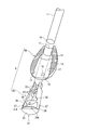
- FIG. 3 is a partially broken perspective view showing an exploded state of the first embodiment.
- the perspective view which shows the assembly state of the said 1st Embodiment.
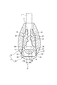
- the cross-sectional view which shows the state before the plug insertion of the said 1st Embodiment.
- the cross-sectional view which shows the state just before the plug engagement of the said 1st Embodiment.
- the top view which shows the plug of 3rd Embodiment of this invention.
- the cross-sectional view along the central axis of the fourth embodiment of the present invention The cross-sectional view along the central axis of the fifth embodiment of the present invention.
- FIGS. 1 to 4 show a first embodiment of the present invention.
- the cord end stopper 9 is attached to the string end 1 ⁇ / b> A for processing the end of the string 1, and is a substantially cylindrical socket into which the string end 1 ⁇ / b> A is inserted.
- 10 and a plug 20 that is inserted into the socket 10 to lock the string end 1A.
- the socket 10 is connected to the string opening 11 into which the string end 1A is inserted, the plug opening 12 into which the plug 20 is inserted, the string opening 11 and the plug opening 12 and is inserted through the string opening 11.
- the plug 20 is formed in the base portion 21 to be attached to the plug opening 12, the leg portion 22 supported by the base portion 21 and inserted into the housing portion 13 from the plug opening 12, and the leg portion 22.
- Each of the socket 10 and the plug 20 is integrally formed with each part shape by a synthetic resin having elasticity.
- the leg part 22 of the plug 20 As for the leg part 22 of the plug 20, a pair is formed in parallel and the string latching
- the string locking portions 23 are sawtooth or conical protrusions alternately formed on the opposing surfaces of the leg portions 22.
- the leg part 22 has a dent inside the part continuing to the base part 21, and is formed to be easily bent at the part. Thereby, the leg part 22 rotates centering on the part which continues to the base 21, and the string end part 1A can be pinched
- the accommodating portion 13 of the socket 10 is formed so that the string opening 11 side is narrower than the plug opening 12 side, and a tapered portion 14 is formed on the inner surface of the accommodating portion 13.
- Each distal end side (the side opposite to the base portion 21) of the leg portion 22 inserted into the accommodating portion 13 is separated from the inner width on the string opening 11 side of the accommodating portion 13 in the absence of external force (FIG. 5).
- each tip abuts against the taper portion 14, and then is displaced in the proximity direction along the taper portion 14 (see FIG. 6).
- the accommodated portion 13 is accommodated in a narrow portion on the string opening 11 side (see FIG. 1). In this state, the leg portions 22 are maintained in close proximity to each other. If the cord end portions 1A are inserted between the pair of leg portions 22, the cord end portions 1A are sandwiched between the respective cord locking portions 23. The string end 1A is held in a locked state.
- the base portion 21 of the plug 20 includes a first member 24 that supports the leg portion 22, a second member 25 that is spaced from the first member 24, and a pair that connects the first member 24 and the second member 25.
- the base member 21 is formed in a rectangular frame shape by the first member 24, the second member 25, and the pair of side members 26, and a hollow space portion 21A is formed inside the base member 21. .
- the first member 24 is connected to both sides of the base end side of the pair of leg portions 22 and one end side of the pair of side members 26, and the leg portion 22 and the side member 26 are connected to each end portion of the first member 24. Is formed to continue in a series.
- the first member 24 has an arcuate bulging portion 24A that bulges toward the space 21A, and a spherical convex engaging portion 28 is formed on the front and back of the arcuate bulging portion 24A.
- the base part of the leg part 22, that is, the part continuing to the base part 21, the opposite sides of the pair of leg parts 22 are recessed in an arc shape, and the part beyond the base of the leg part 22 (the string locking part 23 is The cross-sectional shape is smaller than the formed part). Due to the depression at the base, the leg portion 22 is elastically deformed exclusively at the base and rotates with the base 21 as a whole with the base as an axis.
- the other end of the pair of side members 26 is connected to both ends of the second member 25. The side opposite to the space portion 21A of the second member 25 is exposed from the plug opening 12 even when assembled as the cord end stopper 9, and constitutes the outer surface of the cord end stopper 9 (FIG. 4). reference).
- the side member 26 is a girder member extending in a direction along the inner surface of the housing portion 13 when the plug 20 is inserted into the socket 10, and is formed thinner (thinner) than the thickness of the first member 24 and the second member 25.
- a spherical convex engaging portion 27 is formed at the intermediate portion of the side member 26 on the side facing the inner surface of the accommodating portion 13. Thereby, the side member 26 can be elastically deformed so that at least a portion where the engaging portion 27 is formed is separated from the inner surface of the accommodating portion 13.
- the engaging portion 27 has a larger convex shape than the engaging portion 28. “Large” means that the radius of the circular convex shape is large and the height of the protrusion from the periphery is also large.
- the accommodating portion 13 is formed with a concave engaged portion 17 that can be engaged with the engaging portion 27, and a concave engaged portion 18 that is engageable with the engaging portion 28. .
- the engaged portion 17 and the engaged portion 18 are arranged at positions where they are engaged with each other when assembled as the cord end stopper 9, and have a spherical concave shape corresponding to the engaging portion 27 and the engaging portion 28. Has been. Accordingly, the plug 20 is inserted into the socket 10 and assembled as the cord end stopper 9, and the engaging portion 27 and the engaged portion 17 and the engaging portion 28 and the engaged portion 18 are engaged with each other.
- the function of preventing the socket 10 from coming off is configured.
- the engaging portion 27 is formed at an intermediate portion of the surface of the side member 26 facing the inner surface of the accommodating portion 13, and the back surface is a space portion 21 ⁇ / b> A.
- the engaging portion 28 is formed in the bulging portion 24A of the first member 24 and is disposed in the space portion 21A.
- the engaging portion 28 is sandwiched between the pair of side members 26 and is preferably disposed at the midpoint position of the pair of side members 26.
- the engaging portion 28 and the engaging portion 27 are arranged at the same position orthogonal to the insertion direction axis of the plug 20 (on the same plane of the virtual plane intersecting the plug insertion direction axis, that is, the central axis of the housing portion 13).
- the engaging portion 28 and the engaging portion 27 are arranged so as to go around the plug 20 in the circumferential direction.
- the engaged portion 18 and the engaged portion 17 are arranged so as to go around the inner circumference of the accommodating portion 13 in the circumferential direction.
- assembly is performed in the following procedure.
- the cord end 1 ⁇ / b> A is inserted from the cord opening 11 into the accommodating portion 13 of the socket 10, and the cord end 1 ⁇ / b> A protruding from the plug opening 12 is sandwiched between the leg portions 22.
- the plug 20 is inserted from the plug opening 12.
- FIG. 6 when the leg portions 22 are inserted from the plug openings 12, the tips of the leg portions 22 come into contact with the tapered portions 14, and then come close to each other along the tapered portions 14.
- the portion 13 is accommodated in a narrow portion on the string opening 11 side.
- leg portions 22 are maintained in a state of being close to each other, and the string end portions 1A between the pair of leg portions 22 are sandwiched by the string locking portions 23 of the respective leg portions 22 so that the string end portions 1A are locked. Done.
- the engaging portion 27 and the engaging portion 28 reach the plug opening 12 and enter the inside thereof.
- the engaging portion 27 receives a reaction force from the inner surface of the accommodating portion 13, but this reaction force is alleviated by the side member 26 being elastically deformed inward, that is, toward the space portion 21A, and the engagement portion 27 is plugged.
- the movement of inserting 20 is not hindered.
- the engaging portion 28 is formed on the first member 24, and its elastic deformation is not as great as the deformation of the side member 26.
- the socket 10 is elastically deformed by a reaction force against the inner surface of the housing portion 13.
- the engaging portion 28 is formed smaller than the engaging portion 27, the engaging portion 28 does not hinder the movement of inserting the plug 20.
- the base portion 21 of the plug 20 is in the plug opening 12.
- the outer surface of the socket 10 and the outer surface of the base portion 21 are maintained in a continuous state. Thereby, the assembly of the cord end stopper 9 is completed.
- the cord end 1A is inserted into the accommodating portion 13 of the socket 10 from the cord opening 11, the cord end 1A is sandwiched between the leg openings 22 from the plug opening 12, and the plug 20 is inserted into the accommodating portion 13.
- the string end 1A is locked by the string locking portion 23 and locked in the accommodating portion 13 over a predetermined length.
- the side on which the string end 1A is inserted (string opening 11) is opposite to the side on which the plug 20 is inserted (plug opening 12), so that the plug 20 is pulled out even if the string 1 is pulled. This prevents the string 1 from coming off.
- the pair of side members 26 on which the engaging portions 27 are formed by the force are elastically deformed.
- the pair of side members 26 has a space 21 ⁇ / b> A on the back side with respect to the surface side on which the engaging portion is formed, and deformation is restricted by a member having rigidity such as the first member 24 and the second member 25. Therefore, the elastic deformation by the reaction force described above is easily performed. For this reason, even when the engagement portion 27 has a shape suitable for the function of preventing removal from the socket 10, for example, a large unevenness, the plug 20 can be easily deformed when inserted into the socket 10, and assembly work can be performed. It can be easily performed and instability in the assembly operation can be avoided.
- the engaging portion 27 is a convex portion formed on the surface of the side member 26 extending along the inner surface of the accommodating portion 13, and a concave engaged portion 17 is formed and engaged with the inner surface of the accommodating portion 13. Since it did in this way, the reliable engagement by these engaging parts 27 and the to-be-engaged part 17 is obtained.
- the engaging portion 27 is convex, the reaction force received by the engaging portion 27 when the plug 20 is inserted into the socket 10 can be alleviated appropriately by the elastic deformation of the side member 26 at all times.
- the engaging portion 27 slides on the inner surface of the housing portion 13 and receives a reaction force until the engaging portion 27 reaches the engaged state with the engaged portion 17. .
- the engaging portion 27 is convex, the corresponding portion of the side member 26 becomes thick, and the strength as an article can be ensured. Further, it is more effective when the engaging portion 27 of the side member 26 is formed to have a convex shape when engaged by elastic deformation.
- a convex engaging portion 28 formed on the first member 25 and a concave engaged portion 18 formed on the inner surface of the accommodating portion 13 are provided, and the engaging portion 28 and the engaged portion 18 are provided. Is engaged together with the engaging portion 27 and the engaged portion 17 described above, the function of preventing the plug 20 from coming off can be strengthened.
- the engaging portion 27 formed on the side member 26 has a larger convex shape than the engaging portion 28 formed on the first member 24, the larger engaging portion 27 provides a stronger retaining function.
- the enlarged engaging portion 27 is formed on the side member 26 and the side member 26 is elastically deformed to the inside of the space portion 21A so that the resistance during the engaging operation is reduced, a retaining function is provided. The easiness of the assembly work can be increased while sufficiently increasing.
- the engaging portion 27 and the engaging portion 28 are arranged at the same position orthogonal to the insertion direction axis of the plug 20, the engagement of the engaging portion 27 and the engaging portion 28 with the socket 10 in the insertion direction of the plug 20. It is performed at the same position, and the engagement function by each can synergistically enhance the function of preventing the plug 20 from coming off.
- the pair of side members 26 are elastically deformed in the engagement portion 27 and the socket 10 is expanded in the engagement portion 28 in the engagement portion 28, the deformation at the time of engagement is different from each other. However, an excessive pushing force is not required.
- the first member 24 is formed with a bulging portion 24A that bulges into the space portion 21A, and an engaging portion 28 is formed on the bulging portion 24A so that the engaging portion 28 can be maintained while maintaining a simple structure.
- the same insertion direction position as the engaging part 27 can be used.
- FIG. 7 shows a second embodiment of the present invention.
- the cord end stopper 9 of the present embodiment has the same configuration as that of the first embodiment described above, but a part of the configuration is different. For this reason, the overlapping description is abbreviate
- the engaging portion 27 formed on the side member 26 of the plug 20 is convex, and the engaged portion is formed on the inner surface of the accommodating portion 13 of the socket 10. 17 was concave.
- a concave engaging portion 27A is formed on the side member 26 of the plug 20, and a convex engaged surface is formed on the inner surface of the accommodating portion 13 of the socket 10.
- a portion 17A is formed.
- the same effect as the first embodiment described above can be obtained.
- the concavities and convexities of the engaging portion 27A and the engaged portion 17A are opposite, the reaction force received by the engaging portion 27 when the plug 20 is inserted into the socket 10 is always appropriately determined by the elastic deformation of the side member 26.
- the effect of alleviating the resistance to the engagement of the engaging portion 27 at all times is an effect obtained only in the first embodiment.
- the engaging portion 27A has a concave shape, a recess is formed in the cross-sectional shape of the side member 26, and the side member 26 has a portion that is more easily bent than other portions.
- the strength of the side member 26 or the base portion 21 can be sufficiently ensured by appropriately designing the cross-sectional shape of the side member 26.
- the convex engaging portion 28 is formed on the first member 24 and the concave engaged portion 18 is formed on the inner surface of the opposing accommodating portion 13. It may be reversed.
- FIG. 8 shows a third embodiment of the present invention.
- the cord end stopper 9 of the present embodiment has the same configuration as that of the first embodiment described above, but a part of the configuration is different. For this reason, the overlapping description is abbreviate
- the first member 24 of the plug 20 is provided with a bulging portion 24A that bulges into the space portion 21A, and the bulging portion 24A has a convex shape on the front and back.
- the engaging portion 28 is formed, and the recessed engaged portion 18 is formed at the opposing portion of the inner surface of the accommodating portion 13 of the socket 10.
- the second member 25 of the plug 20 is provided with a bulging portion 25A that bulges into the space portion 21A, and convex engagement portions 28A are formed on the front and back of the bulging portion 25A.
- Corresponding engaged portions are appropriately formed at opposing portions of the inner surface of the accommodating portion 13 of the socket 10.
- the leg portion 22 has a semicircular cross section, and is formed so as to have a circular cross section when the pair faces each other. It had been.
- the cross-sectional shape of the leg portion 22 is a T-shape, and the rib 22B is formed on the plate-like main body 22A on which the sawtooth string locking portion 23 is formed. Yes.
- the same effect as the first embodiment described above can be obtained.
- the engaging portion 28A is formed on the second member 25 side (the bulging portion 25A of the second member 25), the engaging portion 28A can be engaged even when it is not desired to increase the depth of the first member 24 or to increase the volume.
- the retaining function by the portion 28A can be enhanced.
- the leg portion 22 has a T-shaped cross section in which a rib 22B is formed on a plate-like main body 22A, the volume of the resin used can be reduced.
- FIG. 9 shows a fourth embodiment of the present invention.
- the cord end stopper 9 of the present embodiment has the same configuration as that of the first embodiment described above, but a part of the configuration is different. For this reason, the overlapping description is abbreviate
- the cord end stopper 9 of the first embodiment accommodates one cord end 1A, but the cord end stopper 9 of the present embodiment accommodates two cord ends 1A. Yes.
- the socket 10 is formed wide so that the two string end portions 1A can be accommodated side by side in the accommodating portion 13.
- a partition member 15 is formed in the housing portion 13 of the socket 10 from the string opening 11 side to the back, and the interior of the housing portion 13 is partitioned into two partitions 13A and 13B from the string opening 11 to the middle portion.
- the two leg portions 22 are formed on the base portion 21 in the same manner as in the first embodiment described above, but each leg portion 22 is inserted into the respective section 13A, 13B and sawtooth formed on the inside thereof.
- a string end portion 1 ⁇ / b> A is sandwiched between the shape-like string engaging portion 23 and the partition member 15.
- the two sections 13A and 13B can accommodate a total of two string end portions 1A, and are prevented from coming off by the string locking portions 23 of the leg portions 22 inserted into the sections, respectively. Even in the case of the portion 1A, the end portion can be processed together by one cord end stopper 9. Furthermore, the cord end stopper 9 of the present embodiment can correspond to the plurality of string end portions 1A by changing the simple configuration of expanding the width of the socket 10 and forming the partition member 15 therein.
- FIG. 10 shows a fifth embodiment of the present invention.
- the cord end stopper 9 of the present embodiment has the same configuration as that of the first embodiment described above, but a part of the configuration is different. For this reason, the overlapping description is abbreviate
- the cord end stopper 9 of the first embodiment accommodates one cord end 1A, but the cord end stopper 9 of the present embodiment accommodates two cord ends 1A. Yes.
- the socket 10 is formed wide so that the two string end portions 1A can be accommodated side by side in the accommodating portion 13.
- the plug 20 only one leg portion 22 is supported on the base portion 21, and string locking portions 23 are formed on both sides of the leg portion 22.
- the leg portion 22 In a state where the plug 20 is inserted into the socket 10, the leg portion 22 is disposed along the central axis of the housing portion 13, and the inside of the housing portion 13 is partitioned into two compartments 13 ⁇ / b> A and 13 ⁇ / b> B. In this state, the string locking portions 23 formed on both sides of the leg portion 22 can hold the string end portion 1 ⁇ / b> A between the inner surface of the accommodating portion 13.
- the two sections 13A and 13B can accommodate a total of two string end portions 1A, and each section is prevented from coming off by a string locking portion 23 directed to the respective sections.
- One cord end stopper 9 can collectively process the end portion.
- the cord end stopper 9 of the present embodiment can combine the leg portions 22 into one and does not require a partition member or the like inside the accommodating portion 13, it can be attached to the plurality of string end portions 1A with a simpler configuration. Can respond.
- the string locking portion 23 for locking the string end 1A is formed on the leg portion 22, but the string locking portion 23 is not limited to a sawtooth shape, a conical protrusion, or the like, but is a rectangular parallelepiped shape. Any irregularities that bite into the end 1A of the cord, such as a shape in which blocks are arranged, or other irregularities, can be used as appropriate.
- the engaging portion 27 and the engaged portion 17 and the engaging portion 28 and the engaged portion 18 are irregularities having spherical surfaces, but these are flat conical irregularities, stripes and grooves.
- the number and arrangement can be appropriately changed in each implementation.
- the outer surface shape of the socket 10 or the cord end stopper 9 is an egg shape. However, these can be a cylindrical shape, a spherical shape, or a block shape in which an arbitrary shape is formed. It is only necessary to form the accommodating portion 13 that can accommodate the string end portion 1A over a predetermined length, and decoration according to the application can be added.
- the socket 10 and the plug 20 are made of a synthetic resin material, but may be made of metal or other materials.
- the socket 10 and the plug 20 are not limited to integral molding using a synthetic resin material or the like, and may be formed from a plurality of members.
- the base portion 21 and the leg portion 22 of the plug 20 may be molded as separate members and assembled.
- the present invention can be used as a cord end stopper attached to the end of a string-like object or a band-like object.
Landscapes
- Engineering & Computer Science (AREA)
- General Engineering & Computer Science (AREA)
- Mechanical Engineering (AREA)
- Buckles (AREA)
Abstract
ソケットとプラグとの組み立て作業が容易かつ安定的に行えるとともに、組み立てられたソケットとプラグとが強固に組み付けられるコードエンドストッパーを提供する。コードエンドストッパー9は、略筒状のソケット10とプラグ20とで構成される。ソケット10は、紐用開口11、プラグ用開口12、これらを連通して紐用開口11から挿入された紐端部1Aを収容する収容部13を有する。プラグ20は、基部21、脚部22、脚部22に形成された紐係止部23を有する。基部21は、第1部材24、第2部材25、一対の側部材26で枠状に形成され、内側に空間部21Aが形成される。側部材26には収容部13の内面に係合する係合部27が形成される。係合部27が収容部13から反力を受けた際に側部材26が空間部21A側へ弾性変形し、組立操作時の抵抗が緩和される。
Description
本発明は、紐状物あるいは帯状物の端部に取り付けられるコードエンドストッパーに関する。
従来、紐は様々な用途で用いられる。例えば、靴や鞄あるいは衣服や装身具における開口部等の封止、寸法等の調整には紐が多用されている。また、物品の連結や貨物の固定等、多様な状況において紐が用いられている。
なお、ここでいう紐とは、結束等が可能ないわゆる紐状体を総称するものであり、一般的な紐、ワイヤ、ケーブル等の他、テープ、ベルトまでを含むものである。
これらの紐では一般に端部処理が行われる。すなわち単に切断しただけの状態では断面の外観あるいは手触りが劣るほか、編んだ素材では解れを生じることがある。端部処理の最も簡単なものは紐に結び目を作ることである。しかし、製造現場においては紐に結び目を作る手間が好ましくなく、さらに製品としての装飾性を高めることの要求もあり、紐端部に専用のコードエンドストッパーを装着することがなされている。
なお、ここでいう紐とは、結束等が可能ないわゆる紐状体を総称するものであり、一般的な紐、ワイヤ、ケーブル等の他、テープ、ベルトまでを含むものである。
これらの紐では一般に端部処理が行われる。すなわち単に切断しただけの状態では断面の外観あるいは手触りが劣るほか、編んだ素材では解れを生じることがある。端部処理の最も簡単なものは紐に結び目を作ることである。しかし、製造現場においては紐に結び目を作る手間が好ましくなく、さらに製品としての装飾性を高めることの要求もあり、紐端部に専用のコードエンドストッパーを装着することがなされている。
従来のコードエンドストッパーとしては、紐端部(紐の端から所定長さの領域)を収容するようにした樹脂成型品が利用されている。具体的には、半割りされた本体がヒンジで連結され、紐状物や帯状物の端部(紐端部)を挟み込む形式のもののほか、筒状のソケットの一方から紐端部を挿入し、反対側から挿入したプラグで紐端部を係止する形式が知られている(特許文献1および特許文献2参照)。
特許文献1に記載された紐の末端処理具は、ソケット(外部ケース)とプラグ(栓部材)とを設け、プラグに一対の脚部(締付部材)を設け、その内側に爪状の係止部(第3膨出部)を形成したものである。この構成では、一対の爪の間に紐1を挟み込むことで、紐が抜ける方向へ移動しようとすると一対の爪がさらに紐にくい込み、これにより抜け止め効果が得られる。
特許文献2に記載された紐状ないし帯状物の端部カバーは、ソケット(雌部材)とプラグ(雄部材)とで構成され、プラグに一対の脚部(挟持用脚部)を設け、その内側に複数の爪状の係止部(突起)を形成し、これらの爪の間に紐を挟み込むことで同様な抜け止め効果を得ている。
特許文献2に記載された紐状ないし帯状物の端部カバーは、ソケット(雌部材)とプラグ(雄部材)とで構成され、プラグに一対の脚部(挟持用脚部)を設け、その内側に複数の爪状の係止部(突起)を形成し、これらの爪の間に紐を挟み込むことで同様な抜け止め効果を得ている。
ところで、前述した特許文献1では、プラグ(栓部材)をソケット(外部ケース)内に留置するために、プラグの基部に凸部(第2膨出部)を形成し、ソケットの凹部(開口の内側周縁)と係合させている。
このような構成では、ソケットにプラグを挿入する際に、凸部あるいは凹部が弾性変形することが必要であり、これらを弾性変形させる押し込み力が必要になる。一方で、凸部が形成されるプラグの基部あるいは凹部が形成されるソケットには、それぞれ抜け止めのために所定の剛性が必要である。このように、プラグの抜け止め性能を高めようとすると、プラグの装着の際に強い押し込み力が要求され、紐端部への装着時の作業性が低下するという問題があった。
このような構成では、ソケットにプラグを挿入する際に、凸部あるいは凹部が弾性変形することが必要であり、これらを弾性変形させる押し込み力が必要になる。一方で、凸部が形成されるプラグの基部あるいは凹部が形成されるソケットには、それぞれ抜け止めのために所定の剛性が必要である。このように、プラグの抜け止め性能を高めようとすると、プラグの装着の際に強い押し込み力が要求され、紐端部への装着時の作業性が低下するという問題があった。
一方、前述した特許文献2では、プラグ(雄部材)をソケット(雌部材)内に留置するために、プラグの頭部に一対の突片を形成し、これに凸部(掛合突部)を形成し、この凸部をソケットの内側に形成された凹部と係合させている。
このような構成では、プラグ側の凸部が突片に形成されているため、それ自体で変形が容易であり、プラグの装着の際に必要な強い押し込み力を緩和することができる。しかし、プラグの装着にあたって、紐端部を挟持する一対の脚部とともに細かな突片をソケット内へ挿入する必要があり、やはり紐端部への装着時の作業性が低下するという問題があった。特に、突片は頭部の両端近傍にあるため、ソケットに対するプラグの位置を適切に保たないと何れかがソケットの開口から外れてしまい、装着が安定的に行えないという問題があった。
このような構成では、プラグ側の凸部が突片に形成されているため、それ自体で変形が容易であり、プラグの装着の際に必要な強い押し込み力を緩和することができる。しかし、プラグの装着にあたって、紐端部を挟持する一対の脚部とともに細かな突片をソケット内へ挿入する必要があり、やはり紐端部への装着時の作業性が低下するという問題があった。特に、突片は頭部の両端近傍にあるため、ソケットに対するプラグの位置を適切に保たないと何れかがソケットの開口から外れてしまい、装着が安定的に行えないという問題があった。
本発明の目的は、ソケットとプラグとの組み立て作業が容易かつ安定的に行えるとともに、組み立てられたソケットとプラグとが強固に組み付けられるコードエンドストッパーを提供することにある。
本発明のコードエンドストッパーは、紐端部が挿入される略筒状のソケットと、前記ソケット内に挿入されて前記紐端部を係止するプラグとを有するコードエンドストッパーであって、
前記ソケットは、前記紐端部が挿入される紐用開口と、前記プラグが挿入されるプラグ用開口と、前記紐用開口および前記プラグ用開口に連通されかつ前記紐用開口から挿入された前記紐端部を所定長さにわたって収容する収容部と、を有し、
前記プラグは、前記プラグ用開口に装着される基部と、前記基部に支持されかつ前記プラグ用開口から前記収容部内へ挿入される脚部と、前記脚部に形成されて前記収容部内の前記紐端部を係止する係止部と、を有し、
前記基部は、前記脚部を支持する第1部材と、前記第1部材から間隔をあけて配置された第2部材と、前記第1部材および前記第2部材を連結する一対の側部材と、前記一対の側部材の間に形成されて前記基部を貫通する孔状の空間部と、前記側部材に形成されて前記収容部の内面に係合可能な係合部と、を有し、
前記一対の側部材は、少なくとも前記係合部が形成された部位が前記空間部の内側へ撓むように変形可能な弾性を有することを特徴とする。
本発明において、脚部としては、基部に一対が支持されて各々の間に紐端部を挟み込む構造が利用できるほか、収容部の内面との間に紐端部を挟み込む構造を採用することもできる。紐端部を係止する係止部としては、脚部の表面に形成された鋸歯状、その他の凹凸形状を採用することができる。
前記ソケットは、前記紐端部が挿入される紐用開口と、前記プラグが挿入されるプラグ用開口と、前記紐用開口および前記プラグ用開口に連通されかつ前記紐用開口から挿入された前記紐端部を所定長さにわたって収容する収容部と、を有し、
前記プラグは、前記プラグ用開口に装着される基部と、前記基部に支持されかつ前記プラグ用開口から前記収容部内へ挿入される脚部と、前記脚部に形成されて前記収容部内の前記紐端部を係止する係止部と、を有し、
前記基部は、前記脚部を支持する第1部材と、前記第1部材から間隔をあけて配置された第2部材と、前記第1部材および前記第2部材を連結する一対の側部材と、前記一対の側部材の間に形成されて前記基部を貫通する孔状の空間部と、前記側部材に形成されて前記収容部の内面に係合可能な係合部と、を有し、
前記一対の側部材は、少なくとも前記係合部が形成された部位が前記空間部の内側へ撓むように変形可能な弾性を有することを特徴とする。
本発明において、脚部としては、基部に一対が支持されて各々の間に紐端部を挟み込む構造が利用できるほか、収容部の内面との間に紐端部を挟み込む構造を採用することもできる。紐端部を係止する係止部としては、脚部の表面に形成された鋸歯状、その他の凹凸形状を採用することができる。
このような本発明においては、紐用開口からソケットの収容部内に紐端部を挿入し、プラグ用開口からプラグを挿入することで、収容部内では紐係止部により紐端部が脚部に係止される。紐の挿入側はプラグの挿入側とは反対であるため、紐が引っ張られてもプラグが抜けることはなく、紐の抜け出しも防止される。一方、紐が引っ張られていない状態でも、プラグは係止部により抜け止めがなされている。
基部は、第1部材、第2部材、一対の側部材により矩形枠状を形成し、その内側には中空の空間部が形成される。一対の側部材は、係合部により収容部の内面に係合することで、プラグのソケットからの抜け止め機能を構成する。
プラグをソケットに挿入する際、係合部が収容部の係合部位に至るまでの間、係合部は収容部の内面に摺動しつつ反力を受け、この反力により係合部が形成された一対の側部材は少なくとも係合部が形成された部位が空間部の内側へ撓むように弾性変形する。一対の側部材は、係合部が形成された表面側に対して裏側が空間部とされ、第1部材や第2部材のような剛性を有するものによって変形を規制されることはないから、前述した反力による空間部の内側方向へ撓むような弾性変形が容易に行われる。
このため、係合部をソケットからの抜け止め機能に適した形状、例えば大きな凹凸にした場合であっても、プラグをソケットに挿入する際には変形が容易となり、組み立て作業を容易に行うことができるとともに、組み立て操作における不安定さを回避することができる。
基部は、第1部材、第2部材、一対の側部材により矩形枠状を形成し、その内側には中空の空間部が形成される。一対の側部材は、係合部により収容部の内面に係合することで、プラグのソケットからの抜け止め機能を構成する。
プラグをソケットに挿入する際、係合部が収容部の係合部位に至るまでの間、係合部は収容部の内面に摺動しつつ反力を受け、この反力により係合部が形成された一対の側部材は少なくとも係合部が形成された部位が空間部の内側へ撓むように弾性変形する。一対の側部材は、係合部が形成された表面側に対して裏側が空間部とされ、第1部材や第2部材のような剛性を有するものによって変形を規制されることはないから、前述した反力による空間部の内側方向へ撓むような弾性変形が容易に行われる。
このため、係合部をソケットからの抜け止め機能に適した形状、例えば大きな凹凸にした場合であっても、プラグをソケットに挿入する際には変形が容易となり、組み立て作業を容易に行うことができるとともに、組み立て操作における不安定さを回避することができる。
本発明のコードエンドストッパーにおいて、前記係合部は前記側部材の前記収容部に対向する面に形成され、前記収容部は、前記係合部と係合可能な被係合部を有することが望ましい。
このような本発明においては、プラグをソケットに挿入する際、係合部が収容部の係合部位に至るまでの間、側部材の係合部が収容部の内面に摺動しつつ対向する収容部からの反力を受け、この反力により側部材が空間部の内側方向へ撓むように弾性変形する。 なお、側部材の係合部を凸状とし、収容部の内面の被係合部を凹状とすることにより、側部材の該当部位が太くなり、物品として強度を確保することができる。また、側部材の係合部を凸状を形成したほうが、弾性変形により係合する際にはより有効である。
収容部の内面に凸状の被係合部を形成し、係合部を凹状に形成することもできるが、この場合には一対の側部材の表面を凸状の被係合部が摺動し、反力を受ける位置が移動するため、凸状の被係合部が摺動する位置が第1部材または第2部材に近い場合など十分な弾性変形が得られないことがある。従って、係合部を凸状、被係合部を凹状とすることが望ましい。
さらに、一対の側部材に凹部を形成すると、当該部位だけ断面積が減少し、脆弱になる可能性もあり、この点でも係合部を凸状、被係合部を凹状とすることが望ましい。
このような本発明においては、プラグをソケットに挿入する際、係合部が収容部の係合部位に至るまでの間、側部材の係合部が収容部の内面に摺動しつつ対向する収容部からの反力を受け、この反力により側部材が空間部の内側方向へ撓むように弾性変形する。 なお、側部材の係合部を凸状とし、収容部の内面の被係合部を凹状とすることにより、側部材の該当部位が太くなり、物品として強度を確保することができる。また、側部材の係合部を凸状を形成したほうが、弾性変形により係合する際にはより有効である。
収容部の内面に凸状の被係合部を形成し、係合部を凹状に形成することもできるが、この場合には一対の側部材の表面を凸状の被係合部が摺動し、反力を受ける位置が移動するため、凸状の被係合部が摺動する位置が第1部材または第2部材に近い場合など十分な弾性変形が得られないことがある。従って、係合部を凸状、被係合部を凹状とすることが望ましい。
さらに、一対の側部材に凹部を形成すると、当該部位だけ断面積が減少し、脆弱になる可能性もあり、この点でも係合部を凸状、被係合部を凹状とすることが望ましい。
本発明のコードエンドストッパーにおいて、前記第1部材または前記第2部材の何れかに形成され、前記側部材に形成された前記係合部とは異なる向きの係合部と、前記収容部に形成されて前記係合部と係合可能な被係合部と、を有することが望ましい。
このような本発明においては、前述した側部材に形成された係合部および対向する収容部内面の被係合部による係合に加え、前記第1部材または前記第2部材の何れかに形成された係合部および対向する収容部内面の被係合部による係合をも利用してプラグの抜け止め機能を構成することができる。
このような本発明においては、前述した側部材に形成された係合部および対向する収容部内面の被係合部による係合に加え、前記第1部材または前記第2部材の何れかに形成された係合部および対向する収容部内面の被係合部による係合をも利用してプラグの抜け止め機能を構成することができる。
本発明のコードエンドストッパーにおいて、第1部材または前記第2部材の何れかに形成された係合部よりも側部材に形成された係合部が大きいことが望ましい。
このような本発明においては、側部材の係合部が空間部の内部に撓むように弾性変形することができるので、より大きな係合部とすることができ、プラグの抜け止め機能を一層高めることができる。
このような本発明においては、側部材の係合部が空間部の内部に撓むように弾性変形することができるので、より大きな係合部とすることができ、プラグの抜け止め機能を一層高めることができる。
本発明のコードエンドストッパーにおいて、前記第1部材または前記第2部材の何れかに形成された前記係合部および前記側部材に形成された前記係合部が前記プラグの挿入方向軸線に垂直に交差する同じ位置に配置されていることが望ましい。
なお、プラグの挿入方向軸線に垂直に交差する同じ位置に配置される、とは、プラグの挿入方向軸線に交差する同じ仮想平面上に各係合部が配置されていることを意味する。第1部材または第2部材の形成される係合部を側部材に形成される係合部と同じ挿入方向位置とするためには、例えば、第1部材または第2部材に空間部の内側へ膨出する膨出部を形成し、その表面に係合部を形成する構成が採用できる。
このような本発明においては、側部材の係合部および第1部材または第2部材の係合部がプラグの挿入方向の同じ位置でソケットと係合するため、これらが相乗してプラグの抜け止め機能を高めることができる。特に、側部材の係合部では係合にあたって一対の側部材が弾性変形し、第1部材または第2部材の係合部では係合にあたってソケットが拡張するため、互いに係合の際の変形が別になる。例えば、第1部材の4面に凸状を形成すると、各々によりソケットが大きく拡げられて過大な抵抗が生じるが、本発明ではソケットを拡げる力は第1部材または第2部材の係合部の2面分だけで済み、同じ位置に設けても過大な押し込み力が必要になることはない。
なお、プラグの挿入方向軸線に垂直に交差する同じ位置に配置される、とは、プラグの挿入方向軸線に交差する同じ仮想平面上に各係合部が配置されていることを意味する。第1部材または第2部材の形成される係合部を側部材に形成される係合部と同じ挿入方向位置とするためには、例えば、第1部材または第2部材に空間部の内側へ膨出する膨出部を形成し、その表面に係合部を形成する構成が採用できる。
このような本発明においては、側部材の係合部および第1部材または第2部材の係合部がプラグの挿入方向の同じ位置でソケットと係合するため、これらが相乗してプラグの抜け止め機能を高めることができる。特に、側部材の係合部では係合にあたって一対の側部材が弾性変形し、第1部材または第2部材の係合部では係合にあたってソケットが拡張するため、互いに係合の際の変形が別になる。例えば、第1部材の4面に凸状を形成すると、各々によりソケットが大きく拡げられて過大な抵抗が生じるが、本発明ではソケットを拡げる力は第1部材または第2部材の係合部の2面分だけで済み、同じ位置に設けても過大な押し込み力が必要になることはない。
本発明のコードエンドストッパーにおいて、前記係合部が形成された前記第1部材または前記第2部材の何れかは、その前記空間部側の部位が前記空間部の内側へ膨出した膨出部を有しており、前記膨出部に前記係合部が形成されていることが望ましい。
このような本発明においては、前記第1部材または前記第2部材の一部を前記空間部の内側へ膨出させることで、この膨出部を一対の側部材の間まで延長させることができ、第1部材または第2部材に形成される係合部を側部材に形成される係合部と同じ挿入方向位置とすることができる。
このような本発明においては、前記第1部材または前記第2部材の一部を前記空間部の内側へ膨出させることで、この膨出部を一対の側部材の間まで延長させることができ、第1部材または第2部材に形成される係合部を側部材に形成される係合部と同じ挿入方向位置とすることができる。
本発明のコードエンドストッパーにおいて、前記収容部内は仕切部材で複数の区画に仕切られており、前記複数の区画にはそれぞれ前記脚部および前記紐端部が挿入されることが望ましい。
このような本発明においては、各紐端部は各区画においてそれぞれ脚部により抜け止めされ、複数の紐端部を1つのコードエンドストッパーで端部処理することができる。
このような本発明においては、各紐端部は各区画においてそれぞれ脚部により抜け止めされ、複数の紐端部を1つのコードエンドストッパーで端部処理することができる。
本発明のコードエンドストッパーにおいて、前記収容部内は前記脚部で複数の区画に仕切られており、前記複数の区画にはそれぞれ前記紐端部が挿入されることが望ましい。
このような本発明においても、各紐端部は各区画においてそれぞれ脚部により抜け止めされ、複数の紐端部を1つのコードエンドストッパーで端部処理することができる。
このような本発明においても、各紐端部は各区画においてそれぞれ脚部により抜け止めされ、複数の紐端部を1つのコードエンドストッパーで端部処理することができる。
1…紐、1A…紐端部、9…コードエンドストッパー、10…ソケット、11…紐用開口、12…プラグ用開口、13…収容部、13A,13B…区画、14…テーパー部、15…仕切部材、17…被係合部、17A…被係合部、18…被係合部、20…プラグ、21…基部、21A…空間部、22…脚部、22A…本体、22B…リブ、23…紐係止部、24…第1部材、25…第2部材、26…側部材、27,27A…係合部、28,28A…係合部。
以下、本発明の実施形態を図面に基づいて説明する。
〔第1実施形態〕
図1ないし図6の各図には本発明の第1実施形態が示されている。
図1ないし図4に示すように、コードエンドストッパー9は、紐1の端部処理のために紐端部1Aに装着されるものであり、紐端部1Aが挿入される略筒状のソケット10と、ソケット10内に挿入されて紐端部1Aを係止するプラグ20とを有する。
ソケット10は、紐端部1Aが挿入される紐用開口11と、プラグ20が挿入されるプラグ用開口12と、紐用開口11およびプラグ用開口12に連通されかつ紐用開口11から挿入された紐端部1Aを所定長さにわたって収容する収容部13と、を有する。
プラグ20は、プラグ用開口12に装着される基部21と、基部21に支持されかつプラグ用開口12から収容部13内へ挿入される脚部22と、脚部22に形成されて収容部13内の紐端部1Aを係止する紐係止部23と、を有する。
これらのソケット10およびプラグ20は、それぞれ弾性を有する合成樹脂により各部形状を一体成形されている。
〔第1実施形態〕
図1ないし図6の各図には本発明の第1実施形態が示されている。
図1ないし図4に示すように、コードエンドストッパー9は、紐1の端部処理のために紐端部1Aに装着されるものであり、紐端部1Aが挿入される略筒状のソケット10と、ソケット10内に挿入されて紐端部1Aを係止するプラグ20とを有する。
ソケット10は、紐端部1Aが挿入される紐用開口11と、プラグ20が挿入されるプラグ用開口12と、紐用開口11およびプラグ用開口12に連通されかつ紐用開口11から挿入された紐端部1Aを所定長さにわたって収容する収容部13と、を有する。
プラグ20は、プラグ用開口12に装着される基部21と、基部21に支持されかつプラグ用開口12から収容部13内へ挿入される脚部22と、脚部22に形成されて収容部13内の紐端部1Aを係止する紐係止部23と、を有する。
これらのソケット10およびプラグ20は、それぞれ弾性を有する合成樹脂により各部形状を一体成形されている。
プラグ20の脚部22は、一対が並列に形成され、互いの対向する側にはそれぞれ紐係止部23が形成されている。紐係止部23は、脚部22の互いの対向面に交互に形成された鋸歯状あるいは円錐状の突起とされている。脚部22は基部21に連続する部分の内側に凹みを有し、当該部分で屈曲しやすく形成されている。これにより、脚部22は基部21に連続する部分を中心に回動し、各々の先端を近接させることにより、各脚部22の間に紐端部1Aを挟むことができる。
ソケット10の収容部13は、紐用開口11側がプラグ用開口12側よりも狭く形成され、収容部13の内面にはテーパー部14が形成されている。収容部13に挿入される脚部22の各先端側(基部21と反対側)は、外力のない状態では収容部13の紐用開口11側の内幅よりも大きく離れているが(図5参照)、脚部22をプラグ用開口12から挿入した際には、各先端がテーパー部14に当接した後、テーパー部14に沿って互いに近接方向へ変位され(図6参照)、狭く形成された収容部13の紐用開口11側の狭い部分へ揃って収容される(図1参照)。この状態では、脚部22は互いに近接した状態で維持され、一対の脚部22の間に紐端部1Aが挿入されていれば、各々の紐係止部23で紐端部1Aが挟み込まれ、紐端部1Aは係止された状態で保持される。
ソケット10の収容部13は、紐用開口11側がプラグ用開口12側よりも狭く形成され、収容部13の内面にはテーパー部14が形成されている。収容部13に挿入される脚部22の各先端側(基部21と反対側)は、外力のない状態では収容部13の紐用開口11側の内幅よりも大きく離れているが(図5参照)、脚部22をプラグ用開口12から挿入した際には、各先端がテーパー部14に当接した後、テーパー部14に沿って互いに近接方向へ変位され(図6参照)、狭く形成された収容部13の紐用開口11側の狭い部分へ揃って収容される(図1参照)。この状態では、脚部22は互いに近接した状態で維持され、一対の脚部22の間に紐端部1Aが挿入されていれば、各々の紐係止部23で紐端部1Aが挟み込まれ、紐端部1Aは係止された状態で保持される。
プラグ20の基部21は、脚部22を支持する第1部材24と、第1部材24から間隔をあけて配置された第2部材25と、第1部材24および第2部材25を連結する一対の側部材26とを有し、これらの第1部材24、第2部材25、一対の側部材26により基部21は矩形枠状に形成され、その内側には中空の空間部21Aが形成される。
第1部材24は、両側に一対の脚部22の基端側が連結されるとともに、一対の側部材26の一端側が連結され、第1部材24の各端部において脚部22と側部材26とが一連に続くように形成されている。第1部材24は空間部21A側へ膨出する円弧状の膨出部24Aを有し、この円弧状の膨出部24Aの表裏には球面凸状の係合部28が形成されている。
なお、脚部22の根元部分、つまり基部21に連続する部分は、一対の脚部22の互いに対向する側が円弧状に凹まされ、脚部22の根元より先の部分(紐係止部23が形成された部分)よりも断面形状が小さく形成されている。この根元に凹みにより、脚部22は専ら根元で弾性変形し、基部21に対して根元を軸に全体が直線状のまま回動するようになっている。
第2部材25は、両端に一対の側部材26の他端側が連結される。第2部材25の空間部21Aとは反対側は、コードエンドストッパー9として組み立てられた際にもプラグ用開口12から露出し、コードエンドストッパー9の外面を構成するものとされている(図4参照)。
第1部材24は、両側に一対の脚部22の基端側が連結されるとともに、一対の側部材26の一端側が連結され、第1部材24の各端部において脚部22と側部材26とが一連に続くように形成されている。第1部材24は空間部21A側へ膨出する円弧状の膨出部24Aを有し、この円弧状の膨出部24Aの表裏には球面凸状の係合部28が形成されている。
なお、脚部22の根元部分、つまり基部21に連続する部分は、一対の脚部22の互いに対向する側が円弧状に凹まされ、脚部22の根元より先の部分(紐係止部23が形成された部分)よりも断面形状が小さく形成されている。この根元に凹みにより、脚部22は専ら根元で弾性変形し、基部21に対して根元を軸に全体が直線状のまま回動するようになっている。
第2部材25は、両端に一対の側部材26の他端側が連結される。第2部材25の空間部21Aとは反対側は、コードエンドストッパー9として組み立てられた際にもプラグ用開口12から露出し、コードエンドストッパー9の外面を構成するものとされている(図4参照)。
側部材26は、プラグ20をソケット10内に挿入した際に収容部13の内面に沿う方向に延びる桁状の部材であり、第1部材24および第2部材25の厚みより薄く(細く)形成されている。
側部材26の中間部には、収容部13の内面に面した側に球面凸状の係合部27が形成されている。これにより、側部材26は、少なくとも係合部27が形成された部位が収容部13の内面から離隔するように弾性変形可能である。
係合部27は係合部28よりも大きい凸状とされている。ここで大きいとは、円形の凸状の半径が大きいとともに、周囲からの突起高さも大きいということである。
側部材26の中間部には、収容部13の内面に面した側に球面凸状の係合部27が形成されている。これにより、側部材26は、少なくとも係合部27が形成された部位が収容部13の内面から離隔するように弾性変形可能である。
係合部27は係合部28よりも大きい凸状とされている。ここで大きいとは、円形の凸状の半径が大きいとともに、周囲からの突起高さも大きいということである。
収容部13には、係合部27と係合可能な凹状の被係合部17が形成されているとともに、係合部28と係合可能な凹状の被係合部18が形成されている。
これらの被係合部17および被係合部18は、コードエンドストッパー9として組み立てられた際に互いに係合する位置に配置され、係合部27および係合部28に対応した球面の凹状とされている。従って、プラグ20をソケット10に挿入してコードエンドストッパー9として組み立て、これらの係合部27と被係合部17および係合部28と被係合部18を係合させることで、プラグ20のソケット10からの抜け止め機能が構成される。
これらの被係合部17および被係合部18は、コードエンドストッパー9として組み立てられた際に互いに係合する位置に配置され、係合部27および係合部28に対応した球面の凹状とされている。従って、プラグ20をソケット10に挿入してコードエンドストッパー9として組み立て、これらの係合部27と被係合部17および係合部28と被係合部18を係合させることで、プラグ20のソケット10からの抜け止め機能が構成される。
係合部27は側部材26の収容部13の内面に対向する表面の中間部に形成され、背面が空間部21Aとされている。係合部28は第1部材24の膨出部24Aに形成され、空間部21A内に配置されている。係合部28は、一対の側部材26の間に挟まれる状態とされ、好ましくは一対の側部材26の中点位置に配置される。これらにより、係合部28および係合部27はプラグ20の挿入方向軸線に直交する同じ位置(プラグの挿入方向軸線つまり収容部13の中心軸線に交差する仮想平面のうち同じ平面上)に配置され、係合部28および係合部27はプラグ20を周方向に一巡するように配列されている。同様に、被係合部18および被係合部17は、収容部13の内周を周方向に一巡するように配列されている。
このような構成により、係合部27と被係合部17および係合部28と被係合部18の係合は、プラグ20のソケット10に対する移動の際に、計4つの部分で同時に発生し、抜け止め機能が個々の凹凸係合の単なる集合よりも大幅に強化される。
このような構成により、係合部27と被係合部17および係合部28と被係合部18の係合は、プラグ20のソケット10に対する移動の際に、計4つの部分で同時に発生し、抜け止め機能が個々の凹凸係合の単なる集合よりも大幅に強化される。
本実施形態においては、次のような手順で組み立てを行う。
図5に示すように、紐用開口11からソケット10の収容部13内に紐端部1Aを挿入し、プラグ用開口12から突出させた紐端部1Aを脚部22の間に挟んだ状態とする。この状態で、プラグ用開口12からプラグ20を挿入する。
図6に示すように、脚部22をプラグ用開口12から挿入すると、各脚部22の先端がテーパー部14に当接した後、テーパー部14に沿って互いに近接し、狭く形成された収容部13の紐用開口11側の狭い部分へ揃って収容される。その結果、脚部22は互いに近接した状態で維持され、一対の脚部22の間の紐端部1Aは各脚部22の紐係止部23により挟み込まれ、紐端部1Aの係止が行われる。
図5に示すように、紐用開口11からソケット10の収容部13内に紐端部1Aを挿入し、プラグ用開口12から突出させた紐端部1Aを脚部22の間に挟んだ状態とする。この状態で、プラグ用開口12からプラグ20を挿入する。
図6に示すように、脚部22をプラグ用開口12から挿入すると、各脚部22の先端がテーパー部14に当接した後、テーパー部14に沿って互いに近接し、狭く形成された収容部13の紐用開口11側の狭い部分へ揃って収容される。その結果、脚部22は互いに近接した状態で維持され、一対の脚部22の間の紐端部1Aは各脚部22の紐係止部23により挟み込まれ、紐端部1Aの係止が行われる。
プラグ20をソケット10内に挿入するに従って、基部21側においては係合部27および係合部28がプラグ用開口12に到達し、その内側に入る。この際、係合部27は収容部13の内面からの反力を受けるが、この反力は側部材26が内側つまり空間部21A側へ弾性変形することで緩和され、係合部27がプラグ20を挿入する動きを妨げることはない。一方、係合部28は第1部材24に形成され、その弾性変形は側部材26の変形ほど大きくない。しかし、係合部28と収容部13の内面とが圧接した際には、収容部13の内面への反力によりソケット10が弾性変形する。係合部28は係合部27よりも小さく形成されているため、係合部28がプラグ20を挿入する動きを妨げることはない。
プラグ20が更に挿入され、係合部27と被係合部17および係合部28と被係合部18の係合がなされると、プラグ20の基部21がプラグ用開口12に収まった状態となり、ソケット10の外面と基部21の外面と連続した状態に維持される。これによりコードエンドストッパー9の組み立てが完成する。
プラグ20が更に挿入され、係合部27と被係合部17および係合部28と被係合部18の係合がなされると、プラグ20の基部21がプラグ用開口12に収まった状態となり、ソケット10の外面と基部21の外面と連続した状態に維持される。これによりコードエンドストッパー9の組み立てが完成する。
本実施形態によれば、以下のような効果がある。
紐用開口11からソケット10の収容部13内に紐端部1Aを挿入し、プラグ用開口12から紐端部1Aを脚部22で挟んだうえでプラグ20を収容部13内へ挿入することで、紐端部1Aは紐係止部23により係止され、所定長さにわたって収容部13内に係止される。この際、紐端部1Aが挿入される側(紐用開口11)はプラグ20が挿入される側(プラグ用開口12)とは反対であるため、紐1が引っ張られてもプラグ20が抜けることはなく、これにより紐1の抜け出しを防止することができる。
紐用開口11からソケット10の収容部13内に紐端部1Aを挿入し、プラグ用開口12から紐端部1Aを脚部22で挟んだうえでプラグ20を収容部13内へ挿入することで、紐端部1Aは紐係止部23により係止され、所定長さにわたって収容部13内に係止される。この際、紐端部1Aが挿入される側(紐用開口11)はプラグ20が挿入される側(プラグ用開口12)とは反対であるため、紐1が引っ張られてもプラグ20が抜けることはなく、これにより紐1の抜け出しを防止することができる。
紐1が引っ張られていない状態でも、基部21とソケット10の収容部13の内面とに形成された抜け止め構造(係合部27と被係合部17および係合部28と被係合部18の係合)により、プラグ20はソケット10からの抜け出しを規制されている。
抜け止め構造は、組み立て状態でプラグ20がソケット10から抜け出すことを規制するが、組み立て操作にあたってはプラグ20の挿入操作に抵抗力を与える。しかし、本発明に基づく抜け止め構造においては、この抵抗力が緩和され、操作を容易かつ安定的とすることができる。
すなわち、プラグ20をソケット10に挿入する際、係合部27が被係合部17に至るまでの間、係合部27は収容部13の内面に摺動しつつ反力を受け、この反力により係合部27が形成された一対の側部材26は弾性変形する。一対の側部材26は、係合部が形成された表面側に対して裏側が空間部21Aとされ、第1部材24や第2部材25のような剛性を有するものによって変形を規制されることはないから、前述した反力による弾性変形が容易に行われる。
このため、係合部27をソケット10からの抜け止め機能に適した形状、例えば大きな凹凸にした場合であっても、プラグ20をソケット10に挿入する際には変形が容易となり、組み立て作業を容易に行うことができるとともに、組み立て操作における不安定さを回避することができる。
抜け止め構造は、組み立て状態でプラグ20がソケット10から抜け出すことを規制するが、組み立て操作にあたってはプラグ20の挿入操作に抵抗力を与える。しかし、本発明に基づく抜け止め構造においては、この抵抗力が緩和され、操作を容易かつ安定的とすることができる。
すなわち、プラグ20をソケット10に挿入する際、係合部27が被係合部17に至るまでの間、係合部27は収容部13の内面に摺動しつつ反力を受け、この反力により係合部27が形成された一対の側部材26は弾性変形する。一対の側部材26は、係合部が形成された表面側に対して裏側が空間部21Aとされ、第1部材24や第2部材25のような剛性を有するものによって変形を規制されることはないから、前述した反力による弾性変形が容易に行われる。
このため、係合部27をソケット10からの抜け止め機能に適した形状、例えば大きな凹凸にした場合であっても、プラグ20をソケット10に挿入する際には変形が容易となり、組み立て作業を容易に行うことができるとともに、組み立て操作における不安定さを回避することができる。
係合部27を収容部13の内面に沿って延びる側部材26の表面に形成された凸状の部分とし、収容部13の内面には凹状の被係合部17を形成して係合させるようにしたため、これらの係合部27と被係合部17とによる確実な係合が得られる。
特に、係合部27を凸状としたため、プラグ20をソケット10に挿入する際に係合部27が受ける反力を常に側部材26の弾性変形で適切に緩和することができる。プラグ20をソケット10に挿入する際、係合部27が被係合部17との係合状態に至るまでの間、係合部27は収容部13の内面に摺動し、反力を受ける。しかし、係合部27が凸であるため、側部材26の該当部位が太くなり、物品として強度を確保することができる。また、側部材26の係合部27を凸状を形成したほうが、弾性変形により係合する際にはより有効である。
特に、係合部27を凸状としたため、プラグ20をソケット10に挿入する際に係合部27が受ける反力を常に側部材26の弾性変形で適切に緩和することができる。プラグ20をソケット10に挿入する際、係合部27が被係合部17との係合状態に至るまでの間、係合部27は収容部13の内面に摺動し、反力を受ける。しかし、係合部27が凸であるため、側部材26の該当部位が太くなり、物品として強度を確保することができる。また、側部材26の係合部27を凸状を形成したほうが、弾性変形により係合する際にはより有効である。
第1部材25に形成された凸状の係合部28と、収容部13の内面に形成された凹状の被係合部18とを設け、これらの係合部28と被係合部18とを、前述した係合部27と被係合部17とともに係合させるようにしたため、プラグ20の抜け止め機能を強化することができる。
ここで、第1部材24に形成する係合部28よりも側部材26に形成する係合部27が大きい凸状となるようにしたため、大きくした係合部27により一層強力な抜け止め機能が得られるとともに、大きくした係合部27は側部材26に形成して側部材26が空間部21Aの内側へ弾性変形することで係合操作時の抵抗が少なくなるようにしたため、抜け止め機能を十分に高めつつ組み立て作業の容易性を高くすることができる。
ここで、第1部材24に形成する係合部28よりも側部材26に形成する係合部27が大きい凸状となるようにしたため、大きくした係合部27により一層強力な抜け止め機能が得られるとともに、大きくした係合部27は側部材26に形成して側部材26が空間部21Aの内側へ弾性変形することで係合操作時の抵抗が少なくなるようにしたため、抜け止め機能を十分に高めつつ組み立て作業の容易性を高くすることができる。
係合部27および係合部28をプラグ20の挿入方向軸線に直交する同じ位置に配置したため、これらの係合部27および係合部28によるソケット10との係合がプラグ20の挿入方向の同じ位置で行われることになり、各々による係合機能が相乗してプラグ20の抜け止め機能を高めることができる。特に、係合部27では係合にあたって一対の側部材26が弾性変形し、係合部28では係合にあたってソケット10が拡張し、互いに係合の際の変形が異なるため、同じ位置に設けても過大な押し込み力が必要になることはない。
第1部材24には空間部21A内へ膨出する膨出部24Aを形成し、この膨出部24Aに係合部28を形成することで、簡単な構造を維持しつつ係合部28を係合部27と同じ挿入方向位置とすることができる。
第1部材24には空間部21A内へ膨出する膨出部24Aを形成し、この膨出部24Aに係合部28を形成することで、簡単な構造を維持しつつ係合部28を係合部27と同じ挿入方向位置とすることができる。
〔第2実施形態〕
図7には本発明の第2実施形態が示されている。本実施形態のコードエンドストッパー9は、前述した第1実施形態と同じ構成を有するが、一部構成が異なる。このため、共通部分については重複する説明を省略し、異なる部分について以下に説明する。
前述した第1実施形態においては、図1にも示すように、プラグ20の側部材26に形成した係合部27が凸状で、ソケット10の収容部13の内面に形成した被係合部17が凹状であるとした。これに対し、本実施形態ではこれらの凹凸が逆になっており、プラグ20の側部材26に凹状の係合部27Aが形成され、ソケット10の収容部13の内面に凸状の被係合部17Aが形成されている。
図7には本発明の第2実施形態が示されている。本実施形態のコードエンドストッパー9は、前述した第1実施形態と同じ構成を有するが、一部構成が異なる。このため、共通部分については重複する説明を省略し、異なる部分について以下に説明する。
前述した第1実施形態においては、図1にも示すように、プラグ20の側部材26に形成した係合部27が凸状で、ソケット10の収容部13の内面に形成した被係合部17が凹状であるとした。これに対し、本実施形態ではこれらの凹凸が逆になっており、プラグ20の側部材26に凹状の係合部27Aが形成され、ソケット10の収容部13の内面に凸状の被係合部17Aが形成されている。
このような本実施形態によっても、前述した第1実施形態と同様な効果が得られる。但し、係合部27Aおよび被係合部17Aの凹凸が逆であるため、プラグ20をソケット10に挿入する際に、係合部27が受ける反力を常に側部材26の弾性変形で適切に緩和し、係合部27の係合に至るまでの抵抗を常に適切に緩和する、という効果は第1実施形態のみ得られる効果となる。
また、係合部27Aが凹状となるため、側部材26の断面形状に凹みが形成され、側部材26には他の部分に比べて屈曲しやすい部分が生じる。但し、側部材26の断面形状を適切に設計することで、側部材26ないし基部21としての強度は十分に確保することができる。
なお、前述した第1実施形態では、第1部材24に凸状の係合部28を形成し、対向する収容部13の内面に凹状の被係合部18を形成したが、これらの凹凸を逆にしてもよい。
また、係合部27Aが凹状となるため、側部材26の断面形状に凹みが形成され、側部材26には他の部分に比べて屈曲しやすい部分が生じる。但し、側部材26の断面形状を適切に設計することで、側部材26ないし基部21としての強度は十分に確保することができる。
なお、前述した第1実施形態では、第1部材24に凸状の係合部28を形成し、対向する収容部13の内面に凹状の被係合部18を形成したが、これらの凹凸を逆にしてもよい。
〔第3実施形態〕
図8には本発明の第3実施形態が示されている。本実施形態のコードエンドストッパー9は、前述した第1実施形態と同じ構成を有するが、一部構成が異なる。このため、共通部分については重複する説明を省略し、異なる部分について以下に説明する。
前述した第1実施形態においては、図1にも示すように、プラグ20の第1部材24に空間部21A内へ膨出する膨出部24Aを設け、この膨出部24Aの表裏に凸状の係合部28を形成し、ソケット10の収容部13の内面の対向する部位に凹状の被係合部18を形成していた。これに対し、本実施形態では、プラグ20の第2部材25に空間部21A内へ膨出する膨出部25Aを設け、この膨出部25Aの表裏に凸状の係合部28Aを形成している。
対応する被係合部(図示省略)については、ソケット10の収容部13の内面の対向する部位に適宜形成する。側部材26に形成する係合部27の位置については、係合部28Aに合わせてプラグ挿入方向位置が同じとなるように調整することが望ましい。
さらに、本実施形態では、前述した第1実施形態においては、図3にも示すように、脚部22は半円形の断面を有し、一対を向かい合わせた際に円形断面となるように形成されていた。これに対し、本実施形態では、脚部22の断面形状がT字型とされ、鋸歯状の紐係止部23が形成された板状の本体22Aにリブ22Bが形成されたものとされている。
図8には本発明の第3実施形態が示されている。本実施形態のコードエンドストッパー9は、前述した第1実施形態と同じ構成を有するが、一部構成が異なる。このため、共通部分については重複する説明を省略し、異なる部分について以下に説明する。
前述した第1実施形態においては、図1にも示すように、プラグ20の第1部材24に空間部21A内へ膨出する膨出部24Aを設け、この膨出部24Aの表裏に凸状の係合部28を形成し、ソケット10の収容部13の内面の対向する部位に凹状の被係合部18を形成していた。これに対し、本実施形態では、プラグ20の第2部材25に空間部21A内へ膨出する膨出部25Aを設け、この膨出部25Aの表裏に凸状の係合部28Aを形成している。
対応する被係合部(図示省略)については、ソケット10の収容部13の内面の対向する部位に適宜形成する。側部材26に形成する係合部27の位置については、係合部28Aに合わせてプラグ挿入方向位置が同じとなるように調整することが望ましい。
さらに、本実施形態では、前述した第1実施形態においては、図3にも示すように、脚部22は半円形の断面を有し、一対を向かい合わせた際に円形断面となるように形成されていた。これに対し、本実施形態では、脚部22の断面形状がT字型とされ、鋸歯状の紐係止部23が形成された板状の本体22Aにリブ22Bが形成されたものとされている。
このような本実施形態によっても、前述した第1実施形態と同様な効果が得られる。
さらに、係合部28Aを第2部材25側(第2部材25の膨出部25A)に形成したため、第1部材24の奥行きを大きくしたくない場合あるいは体積を大きくしたくない場合でも係合部28Aによる抜け止め機能の強化を図ることができる。
また、脚部22を板状の本体22Aにリブ22Bを形成した断面T字状としたため、体積を減らして使用する樹脂の低減を図ることもできる。
さらに、係合部28Aを第2部材25側(第2部材25の膨出部25A)に形成したため、第1部材24の奥行きを大きくしたくない場合あるいは体積を大きくしたくない場合でも係合部28Aによる抜け止め機能の強化を図ることができる。
また、脚部22を板状の本体22Aにリブ22Bを形成した断面T字状としたため、体積を減らして使用する樹脂の低減を図ることもできる。
〔第4実施形態〕
図9には本発明の第4実施形態が示されている。本実施形態のコードエンドストッパー9は、前述した第1実施形態と同様な構成を有するが、一部構成が異なる。このため、共通部分については重複する説明を省略し、異なる部分について以下に説明する。
前記第1実施形態のコードエンドストッパー9は1本の紐端部1Aを収容するものであったが、本実施形態のコードエンドストッパー9は2本の紐端部1Aを収容するものとされている。
本実施形態において、ソケット10は収容部13内に紐端部1Aを2本並べて収容できるように幅が広く形成されている。ソケット10の収容部13内には紐用開口11側から奥へ仕切部材15が形成され、収容部13の内部は紐用開口11から中間部分にかけて2つの区画13A,13Bに仕切られている。脚部22は基部21に2本形成されている点は前述した第1実施形態と同様であるが、各脚部22はそれぞれの区画13A,13Bに挿入され、各々の内側に形成された鋸歯状の紐係止部23が仕切部材15との間に紐端部1Aを挟持するようになっている。
図9には本発明の第4実施形態が示されている。本実施形態のコードエンドストッパー9は、前述した第1実施形態と同様な構成を有するが、一部構成が異なる。このため、共通部分については重複する説明を省略し、異なる部分について以下に説明する。
前記第1実施形態のコードエンドストッパー9は1本の紐端部1Aを収容するものであったが、本実施形態のコードエンドストッパー9は2本の紐端部1Aを収容するものとされている。
本実施形態において、ソケット10は収容部13内に紐端部1Aを2本並べて収容できるように幅が広く形成されている。ソケット10の収容部13内には紐用開口11側から奥へ仕切部材15が形成され、収容部13の内部は紐用開口11から中間部分にかけて2つの区画13A,13Bに仕切られている。脚部22は基部21に2本形成されている点は前述した第1実施形態と同様であるが、各脚部22はそれぞれの区画13A,13Bに挿入され、各々の内側に形成された鋸歯状の紐係止部23が仕切部材15との間に紐端部1Aを挟持するようになっている。
このような本実施形態によっても、前述した第1実施形態と同様な効果が得られる。
さらに、2つの区画13A,13Bにより計2本の紐端部1Aを収容することができ、各区画においてそれぞれに挿入される脚部22の紐係止部23により抜け止めされ、複数の紐端部1Aであっても1つのコードエンドストッパー9でまとめて端部処理することができる。
さらに、本実施形態のコードエンドストッパー9は、ソケット10の幅を拡げ、かつ内部に仕切部材15を形成するという簡単な構成の変更で複数の紐端部1Aに対応することができる。
さらに、2つの区画13A,13Bにより計2本の紐端部1Aを収容することができ、各区画においてそれぞれに挿入される脚部22の紐係止部23により抜け止めされ、複数の紐端部1Aであっても1つのコードエンドストッパー9でまとめて端部処理することができる。
さらに、本実施形態のコードエンドストッパー9は、ソケット10の幅を拡げ、かつ内部に仕切部材15を形成するという簡単な構成の変更で複数の紐端部1Aに対応することができる。
〔第5実施形態〕
図10には本発明の第5実施形態が示されている。本実施形態のコードエンドストッパー9は、前述した第1実施形態と同様な構成を有するが、一部構成が異なる。このため、共通部分については重複する説明を省略し、異なる部分について以下に説明する。
前記第1実施形態のコードエンドストッパー9は1本の紐端部1Aを収容するものであったが、本実施形態のコードエンドストッパー9は2本の紐端部1Aを収容するものとされている。
本実施形態において、ソケット10は収容部13内に紐端部1Aを2本並べて収容できるように幅が広く形成されている。プラグ20は、基部21に脚部22が1本だけ支持され、脚部22の両側には紐係止部23が形成されている。ソケット10にプラグ20を挿入した状態では、脚部22が収容部13の中心軸線に沿って配置され、収容部13の内部を2つの区画13A,13Bに仕切るようになっている。この状態で、脚部22の両側に形成された紐係止部23は、それぞれ収容部13の内面との間に紐端部1Aを挟持することが可能である。
図10には本発明の第5実施形態が示されている。本実施形態のコードエンドストッパー9は、前述した第1実施形態と同様な構成を有するが、一部構成が異なる。このため、共通部分については重複する説明を省略し、異なる部分について以下に説明する。
前記第1実施形態のコードエンドストッパー9は1本の紐端部1Aを収容するものであったが、本実施形態のコードエンドストッパー9は2本の紐端部1Aを収容するものとされている。
本実施形態において、ソケット10は収容部13内に紐端部1Aを2本並べて収容できるように幅が広く形成されている。プラグ20は、基部21に脚部22が1本だけ支持され、脚部22の両側には紐係止部23が形成されている。ソケット10にプラグ20を挿入した状態では、脚部22が収容部13の中心軸線に沿って配置され、収容部13の内部を2つの区画13A,13Bに仕切るようになっている。この状態で、脚部22の両側に形成された紐係止部23は、それぞれ収容部13の内面との間に紐端部1Aを挟持することが可能である。
このような本実施形態によっても、前述した第1実施形態と同様な効果が得られる。
さらに、2つの区画13A,13Bにより計2本の紐端部1Aを収容することができ、各区画においてそれぞれに向かう紐係止部23により抜け止めされ、複数の紐端部1Aであっても1つのコードエンドストッパー9でまとめて端部処理することができる。
さらに、本実施形態のコードエンドストッパー9は、脚部22を1本にまとめることができ、収容部13の内部に仕切部材等も必要ないため、一層簡単な構成で複数の紐端部1Aに対応することができる。
さらに、2つの区画13A,13Bにより計2本の紐端部1Aを収容することができ、各区画においてそれぞれに向かう紐係止部23により抜け止めされ、複数の紐端部1Aであっても1つのコードエンドストッパー9でまとめて端部処理することができる。
さらに、本実施形態のコードエンドストッパー9は、脚部22を1本にまとめることができ、収容部13の内部に仕切部材等も必要ないため、一層簡単な構成で複数の紐端部1Aに対応することができる。
〔変形例〕
なお、本発明は前述した各実施形態に限定されるものではなく、以下に示すような変形も含むものである。
前記各実施形態では、紐端部1Aを係止するための紐係止部23を脚部22に形成したが、紐係止部23は鋸歯状、円錐状突起等に限らず、直方体状のブロックが並んだ形状その他の凹凸など、紐端部1Aに食い込むような凹凸であれば適宜利用することができる。
前記各実施形態において、係合部27と被係合部17、係合部28と被係合部18はそれぞれ球面を有する凹凸としたが、これらは扁平な円錐形状の凹凸、条線と溝など他の形状であってもよい。
前記各実施形態において、脚部22の数および配置、脚部22における紐係止部23の数及び配置、係合部27と被係合部17、係合部28と被係合部18の数および配置は、それぞれ実施にあたって適宜変更することができる。
なお、本発明は前述した各実施形態に限定されるものではなく、以下に示すような変形も含むものである。
前記各実施形態では、紐端部1Aを係止するための紐係止部23を脚部22に形成したが、紐係止部23は鋸歯状、円錐状突起等に限らず、直方体状のブロックが並んだ形状その他の凹凸など、紐端部1Aに食い込むような凹凸であれば適宜利用することができる。
前記各実施形態において、係合部27と被係合部17、係合部28と被係合部18はそれぞれ球面を有する凹凸としたが、これらは扁平な円錐形状の凹凸、条線と溝など他の形状であってもよい。
前記各実施形態において、脚部22の数および配置、脚部22における紐係止部23の数及び配置、係合部27と被係合部17、係合部28と被係合部18の数および配置は、それぞれ実施にあたって適宜変更することができる。
前記各実施形態において、ソケット10あるいはコードエンドストッパー9としての外面形状を卵形としたが、これらは筒状、球状、任意の形状が形成されたブロック状とすることができ、ソケット10内に所定長さにわたって紐端部1Aが収容できる収容部13が形成できればよく、用途に応じた装飾を追加することができる。
前記各実施形態において、ソケット10およびプラグ20は合成樹脂材料としたが、金属あるいは他の材料としてもよい。ソケット10およびプラグ20はそれぞれ合成樹脂材料等による一体成形に限らず、複数の部材から形成してもよい。例えば、プラグ20の基部21と脚部22とを別部材として成型し、組み立てるとしてもよい。
前記各実施形態において、ソケット10およびプラグ20は合成樹脂材料としたが、金属あるいは他の材料としてもよい。ソケット10およびプラグ20はそれぞれ合成樹脂材料等による一体成形に限らず、複数の部材から形成してもよい。例えば、プラグ20の基部21と脚部22とを別部材として成型し、組み立てるとしてもよい。
本発明は、紐状物あるいは帯状物の端部に取り付けられるコードエンドストッパーとして利用できる。
Claims (8)
- 紐端部1Aが挿入される略筒状のソケット10と、前記ソケット10内に挿入されて前記紐端部1Aを係止するプラグ20とを有するコードエンドストッパーであって、
前記ソケット10は、前記紐端部1Aが挿入される紐用開口11と、前記プラグ20が挿入されるプラグ用開口12と、前記紐用開口11および前記プラグ用開口12に連通されかつ前記紐用開口11から挿入された前記紐端部1Aを所定長さにわたって収容する収容部13と、を有し、
前記プラグ20は、前記プラグ用開口12に装着される基部21と、前記基部21に支持されかつ前記プラグ用開口12から前記収容部13内へ挿入される脚部22と、前記脚部22に形成されて前記収容部13内の前記紐端部1Aを係止する紐係止部23と、を有し、
前記基部21は、前記脚部22を支持する第1部材24と、前記第1部材24から間隔をあけて配置された第2部材25と、前記第1部材24および前記第2部材25を連結する一対の側部材26と、前記一対の側部材26の間に形成されて前記基部21を貫通する孔状の空間部21Aと、前記側部材26に形成されて前記収容部13の内面に係合可能な係合部27,27Aと、を有し、
前記一対の側部材26は、少なくとも前記係合部27,27Aが形成された部位が前記空間部の内側へ撓むように変形可能な弾性を有する
ことを特徴とするコードエンドストッパー。 - 前記係合部27,27Aは前記側部材26の前記収容部13に対向する面に形成され、
前記収容部13は、前記係合部27,27Aと係合可能な被係合部17,17Aを有する
ことを特徴とする請求項1に記載のコードエンドストッパー。 - 前記第1部材24または前記第2部材25の何れかに形成され、前記側部材26に形成された前記係合部27,27Aとは異なる向きの係合部28,28Aと、
前記収容部13に形成されて前記係合部28,28Aと係合可能な被係合部18と、を有する
ことを特徴とする請求項1または請求項2に記載のコードエンドストッパー。 - 前記第1部材24または前記第2部材25の何れかに形成された前記係合部28,28Aよりも前記側部材26に形成された前記係合部27,27Aが大きい
ことを特徴とする請求項3に記載のコードエンドストッパー。 - 前記第1部材24または前記第2部材25の何れかに形成された前記係合部28,28Aおよび前記側部材26に形成された前記係合部27,27Aが前記プラグ20の挿入方向軸線に垂直に交差する同じ位置に配置されている
ことを特徴とする請求項3または請求項4の何れかに記載のコードエンドストッパー。 - 前記係合部28,28Aが形成された前記第1部材24または前記第2部材25の何れかは、その前記空間部21A側の部位が前記空間部21Aの内側へ膨出した膨出部24A,25Aを有し、
前記膨出部24A,25Aに前記係合部28,28Aが形成されている
ことを特徴とする請求項3から請求項5の何れかに記載のコードエンドストッパー。 - 前記収容部13内は仕切部材15で複数の区画13A,13Bに仕切られており、
前記複数の区画13A,13Bにはそれぞれ前記脚部22および前記紐端部1Aが挿入される
ことを特徴とする請求項1から請求項6の何れかに記載のコードエンドストッパー。 - 前記収容部13内は前記脚部22で複数の区画13A,13Bに仕切られており、
前記複数の区画13A,13Bにはそれぞれ前記紐端部1Aが挿入される
ことを特徴とする請求項1から請求項6の何れかに記載のコードエンドストッパー。
Priority Applications (2)
| Application Number | Priority Date | Filing Date | Title |
|---|---|---|---|
| PCT/JP2008/073598 WO2010073340A1 (ja) | 2008-12-25 | 2008-12-25 | コードエンドストッパー |
| TW098112058A TW201024499A (en) | 2008-12-25 | 2009-04-10 | Cord end stopper |
Applications Claiming Priority (1)
| Application Number | Priority Date | Filing Date | Title |
|---|---|---|---|
| PCT/JP2008/073598 WO2010073340A1 (ja) | 2008-12-25 | 2008-12-25 | コードエンドストッパー |
Publications (1)
| Publication Number | Publication Date |
|---|---|
| WO2010073340A1 true WO2010073340A1 (ja) | 2010-07-01 |
Family
ID=42287008
Family Applications (1)
| Application Number | Title | Priority Date | Filing Date |
|---|---|---|---|
| PCT/JP2008/073598 Ceased WO2010073340A1 (ja) | 2008-12-25 | 2008-12-25 | コードエンドストッパー |
Country Status (2)
| Country | Link |
|---|---|
| TW (1) | TW201024499A (ja) |
| WO (1) | WO2010073340A1 (ja) |
Cited By (5)
| Publication number | Priority date | Publication date | Assignee | Title |
|---|---|---|---|---|
| WO2012086611A1 (ja) * | 2010-12-22 | 2012-06-28 | 株式会社ニフコ | 紐止め具 |
| JP2013215363A (ja) * | 2012-04-06 | 2013-10-24 | Nifco Inc | 紐端部装着具 |
| ITUA20164479A1 (it) * | 2016-06-17 | 2017-12-17 | Emplast S R L | Dispositivo terminale per una estremità di un mezzo a corda |
| DE202019002949U1 (de) | 2018-08-03 | 2019-07-31 | Peter Büdel GmbH | Zwei-Komponenten-Schnurendkappe aus Metall mit Einrasten durch Schieben |
| DE202019002948U1 (de) | 2018-09-20 | 2019-08-01 | Peter Büdel GmbH | Zwei-Komponenten-Schnurendkappe aus Kunststoff mit Einrasten durch Druck |
Families Citing this family (1)
| Publication number | Priority date | Publication date | Assignee | Title |
|---|---|---|---|---|
| JP7529491B2 (ja) * | 2019-09-19 | 2024-08-06 | Ykk株式会社 | 紐止め具 |
Citations (4)
| Publication number | Priority date | Publication date | Assignee | Title |
|---|---|---|---|---|
| JP2001057732A (ja) * | 1999-08-12 | 2001-02-27 | Kaneko Seisakusho:Kk | 端末処理具 |
| JP2005296178A (ja) * | 2004-04-08 | 2005-10-27 | Nifco Inc | 紐の端部カバー |
| JP2006204602A (ja) * | 2005-01-28 | 2006-08-10 | Ykk Corp | 紐止め具 |
| JP4040451B2 (ja) * | 2002-12-24 | 2008-01-30 | 株式会社ニフコ | 紐状ないしは帯状物の端部カバー |
-
2008
- 2008-12-25 WO PCT/JP2008/073598 patent/WO2010073340A1/ja not_active Ceased
-
2009
- 2009-04-10 TW TW098112058A patent/TW201024499A/zh unknown
Patent Citations (4)
| Publication number | Priority date | Publication date | Assignee | Title |
|---|---|---|---|---|
| JP2001057732A (ja) * | 1999-08-12 | 2001-02-27 | Kaneko Seisakusho:Kk | 端末処理具 |
| JP4040451B2 (ja) * | 2002-12-24 | 2008-01-30 | 株式会社ニフコ | 紐状ないしは帯状物の端部カバー |
| JP2005296178A (ja) * | 2004-04-08 | 2005-10-27 | Nifco Inc | 紐の端部カバー |
| JP2006204602A (ja) * | 2005-01-28 | 2006-08-10 | Ykk Corp | 紐止め具 |
Cited By (6)
| Publication number | Priority date | Publication date | Assignee | Title |
|---|---|---|---|---|
| WO2012086611A1 (ja) * | 2010-12-22 | 2012-06-28 | 株式会社ニフコ | 紐止め具 |
| JP2012130538A (ja) * | 2010-12-22 | 2012-07-12 | Nifco Inc | 紐止め具 |
| JP2013215363A (ja) * | 2012-04-06 | 2013-10-24 | Nifco Inc | 紐端部装着具 |
| ITUA20164479A1 (it) * | 2016-06-17 | 2017-12-17 | Emplast S R L | Dispositivo terminale per una estremità di un mezzo a corda |
| DE202019002949U1 (de) | 2018-08-03 | 2019-07-31 | Peter Büdel GmbH | Zwei-Komponenten-Schnurendkappe aus Metall mit Einrasten durch Schieben |
| DE202019002948U1 (de) | 2018-09-20 | 2019-08-01 | Peter Büdel GmbH | Zwei-Komponenten-Schnurendkappe aus Kunststoff mit Einrasten durch Druck |
Also Published As
| Publication number | Publication date |
|---|---|
| TW201024499A (en) | 2010-07-01 |
Similar Documents
| Publication | Publication Date | Title |
|---|---|---|
| US10063007B2 (en) | Wire cover | |
| JP6266226B2 (ja) | 施錠可能バックル | |
| US7979966B2 (en) | Buckle | |
| US2895003A (en) | Strain relief grommet | |
| KR100713768B1 (ko) | 끈 고정구 | |
| JPH08332104A (ja) | 紐止め具 | |
| JP2019047949A (ja) | コードロック | |
| WO2013175634A1 (ja) | バックル | |
| WO2013121559A1 (ja) | バックル | |
| EP3808998B1 (en) | Dual component sealing fastener and coupling assembly including same | |
| WO2013027861A1 (en) | Connector | |
| WO2011064885A1 (ja) | 紐止め具 | |
| JP2011155819A (ja) | バンド型クランプ | |
| TW201024499A (en) | Cord end stopper | |
| US10236618B1 (en) | Connector assembly with dress cover | |
| JP4040451B2 (ja) | 紐状ないしは帯状物の端部カバー | |
| WO2013024679A1 (ja) | コードロック | |
| JP2008180337A (ja) | スナップフィット構造および挿入荷重低減方法 | |
| US20170313484A1 (en) | Lashing belt | |
| JP2022531772A5 (ja) | ||
| JP2016195479A (ja) | ワイヤハーネスの固定構造 | |
| JP6605296B2 (ja) | バックル | |
| JP2005228575A (ja) | 防水コネクタ | |
| WO2016114085A1 (ja) | コネクタ | |
| JP7696846B2 (ja) | コードエンド |
Legal Events
| Date | Code | Title | Description |
|---|---|---|---|
| 121 | Ep: the epo has been informed by wipo that ep was designated in this application |
Ref document number: 08879136 Country of ref document: EP Kind code of ref document: A1 |
|
| NENP | Non-entry into the national phase |
Ref country code: DE |
|
| NENP | Non-entry into the national phase |
Ref country code: JP |
|
| 122 | Ep: pct application non-entry in european phase |
Ref document number: 08879136 Country of ref document: EP Kind code of ref document: A1 |