WO2010070965A1 - 方向性電磁鋼板及びその製造方法 - Google Patents
方向性電磁鋼板及びその製造方法 Download PDFInfo
- Publication number
- WO2010070965A1 WO2010070965A1 PCT/JP2009/067017 JP2009067017W WO2010070965A1 WO 2010070965 A1 WO2010070965 A1 WO 2010070965A1 JP 2009067017 W JP2009067017 W JP 2009067017W WO 2010070965 A1 WO2010070965 A1 WO 2010070965A1
- Authority
- WO
- WIPO (PCT)
- Prior art keywords
- steel strip
- steel sheet
- oriented electrical
- electrical steel
- grain
- Prior art date
Links
Images


Classifications
-
- C—CHEMISTRY; METALLURGY
- C22—METALLURGY; FERROUS OR NON-FERROUS ALLOYS; TREATMENT OF ALLOYS OR NON-FERROUS METALS
- C22C—ALLOYS
- C22C38/00—Ferrous alloys, e.g. steel alloys
- C22C38/18—Ferrous alloys, e.g. steel alloys containing chromium
- C22C38/34—Ferrous alloys, e.g. steel alloys containing chromium with more than 1.5% by weight of silicon
-
- C—CHEMISTRY; METALLURGY
- C21—METALLURGY OF IRON
- C21D—MODIFYING THE PHYSICAL STRUCTURE OF FERROUS METALS; GENERAL DEVICES FOR HEAT TREATMENT OF FERROUS OR NON-FERROUS METALS OR ALLOYS; MAKING METAL MALLEABLE, e.g. BY DECARBURISATION OR TEMPERING
- C21D1/00—General methods or devices for heat treatment, e.g. annealing, hardening, quenching or tempering
- C21D1/74—Methods of treatment in inert gas, controlled atmosphere, vacuum or pulverulent material
- C21D1/76—Adjusting the composition of the atmosphere
-
- C—CHEMISTRY; METALLURGY
- C21—METALLURGY OF IRON
- C21D—MODIFYING THE PHYSICAL STRUCTURE OF FERROUS METALS; GENERAL DEVICES FOR HEAT TREATMENT OF FERROUS OR NON-FERROUS METALS OR ALLOYS; MAKING METAL MALLEABLE, e.g. BY DECARBURISATION OR TEMPERING
- C21D8/00—Modifying the physical properties by deformation combined with, or followed by, heat treatment
- C21D8/12—Modifying the physical properties by deformation combined with, or followed by, heat treatment during manufacturing of articles with special electromagnetic properties
- C21D8/1277—Modifying the physical properties by deformation combined with, or followed by, heat treatment during manufacturing of articles with special electromagnetic properties involving a particular surface treatment
- C21D8/1283—Application of a separating or insulating coating
-
- C—CHEMISTRY; METALLURGY
- C22—METALLURGY; FERROUS OR NON-FERROUS ALLOYS; TREATMENT OF ALLOYS OR NON-FERROUS METALS
- C22C—ALLOYS
- C22C38/00—Ferrous alloys, e.g. steel alloys
- C22C38/001—Ferrous alloys, e.g. steel alloys containing N
-
- C—CHEMISTRY; METALLURGY
- C22—METALLURGY; FERROUS OR NON-FERROUS ALLOYS; TREATMENT OF ALLOYS OR NON-FERROUS METALS
- C22C—ALLOYS
- C22C38/00—Ferrous alloys, e.g. steel alloys
- C22C38/004—Very low carbon steels, i.e. having a carbon content of less than 0,01%
-
- C—CHEMISTRY; METALLURGY
- C22—METALLURGY; FERROUS OR NON-FERROUS ALLOYS; TREATMENT OF ALLOYS OR NON-FERROUS METALS
- C22C—ALLOYS
- C22C38/00—Ferrous alloys, e.g. steel alloys
- C22C38/02—Ferrous alloys, e.g. steel alloys containing silicon
-
- C—CHEMISTRY; METALLURGY
- C22—METALLURGY; FERROUS OR NON-FERROUS ALLOYS; TREATMENT OF ALLOYS OR NON-FERROUS METALS
- C22C—ALLOYS
- C22C38/00—Ferrous alloys, e.g. steel alloys
- C22C38/04—Ferrous alloys, e.g. steel alloys containing manganese
-
- C—CHEMISTRY; METALLURGY
- C22—METALLURGY; FERROUS OR NON-FERROUS ALLOYS; TREATMENT OF ALLOYS OR NON-FERROUS METALS
- C22C—ALLOYS
- C22C38/00—Ferrous alloys, e.g. steel alloys
- C22C38/06—Ferrous alloys, e.g. steel alloys containing aluminium
-
- C—CHEMISTRY; METALLURGY
- C23—COATING METALLIC MATERIAL; COATING MATERIAL WITH METALLIC MATERIAL; CHEMICAL SURFACE TREATMENT; DIFFUSION TREATMENT OF METALLIC MATERIAL; COATING BY VACUUM EVAPORATION, BY SPUTTERING, BY ION IMPLANTATION OR BY CHEMICAL VAPOUR DEPOSITION, IN GENERAL; INHIBITING CORROSION OF METALLIC MATERIAL OR INCRUSTATION IN GENERAL
- C23C—COATING METALLIC MATERIAL; COATING MATERIAL WITH METALLIC MATERIAL; SURFACE TREATMENT OF METALLIC MATERIAL BY DIFFUSION INTO THE SURFACE, BY CHEMICAL CONVERSION OR SUBSTITUTION; COATING BY VACUUM EVAPORATION, BY SPUTTERING, BY ION IMPLANTATION OR BY CHEMICAL VAPOUR DEPOSITION, IN GENERAL
- C23C8/00—Solid state diffusion of only non-metal elements into metallic material surfaces; Chemical surface treatment of metallic material by reaction of the surface with a reactive gas, leaving reaction products of surface material in the coating, e.g. conversion coatings, passivation of metals
- C23C8/06—Solid state diffusion of only non-metal elements into metallic material surfaces; Chemical surface treatment of metallic material by reaction of the surface with a reactive gas, leaving reaction products of surface material in the coating, e.g. conversion coatings, passivation of metals using gases
- C23C8/08—Solid state diffusion of only non-metal elements into metallic material surfaces; Chemical surface treatment of metallic material by reaction of the surface with a reactive gas, leaving reaction products of surface material in the coating, e.g. conversion coatings, passivation of metals using gases only one element being applied
- C23C8/24—Nitriding
- C23C8/26—Nitriding of ferrous surfaces
-
- C—CHEMISTRY; METALLURGY
- C23—COATING METALLIC MATERIAL; COATING MATERIAL WITH METALLIC MATERIAL; CHEMICAL SURFACE TREATMENT; DIFFUSION TREATMENT OF METALLIC MATERIAL; COATING BY VACUUM EVAPORATION, BY SPUTTERING, BY ION IMPLANTATION OR BY CHEMICAL VAPOUR DEPOSITION, IN GENERAL; INHIBITING CORROSION OF METALLIC MATERIAL OR INCRUSTATION IN GENERAL
- C23C—COATING METALLIC MATERIAL; COATING MATERIAL WITH METALLIC MATERIAL; SURFACE TREATMENT OF METALLIC MATERIAL BY DIFFUSION INTO THE SURFACE, BY CHEMICAL CONVERSION OR SUBSTITUTION; COATING BY VACUUM EVAPORATION, BY SPUTTERING, BY ION IMPLANTATION OR BY CHEMICAL VAPOUR DEPOSITION, IN GENERAL
- C23C8/00—Solid state diffusion of only non-metal elements into metallic material surfaces; Chemical surface treatment of metallic material by reaction of the surface with a reactive gas, leaving reaction products of surface material in the coating, e.g. conversion coatings, passivation of metals
- C23C8/80—After-treatment
-
- Y—GENERAL TAGGING OF NEW TECHNOLOGICAL DEVELOPMENTS; GENERAL TAGGING OF CROSS-SECTIONAL TECHNOLOGIES SPANNING OVER SEVERAL SECTIONS OF THE IPC; TECHNICAL SUBJECTS COVERED BY FORMER USPC CROSS-REFERENCE ART COLLECTIONS [XRACs] AND DIGESTS
- Y10—TECHNICAL SUBJECTS COVERED BY FORMER USPC
- Y10T—TECHNICAL SUBJECTS COVERED BY FORMER US CLASSIFICATION
- Y10T428/00—Stock material or miscellaneous articles
- Y10T428/24—Structurally defined web or sheet [e.g., overall dimension, etc.]
- Y10T428/24942—Structurally defined web or sheet [e.g., overall dimension, etc.] including components having same physical characteristic in differing degree
- Y10T428/2495—Thickness [relative or absolute]
Definitions
- the present invention relates to a grain-oriented electrical steel sheet suitable for an iron core of electrical equipment such as a transformer and a transformer, and a method for manufacturing the same.
- an insulating film called a glass coating is formed on the surface of a steel strip during finish annealing, and the crystal orientation is controlled using an AlN precipitate as an inhibitor. Tensile tension acts on the steel strip by the glass coating, and the iron loss of the grain-oriented electrical steel sheet is reduced.
- the glass coating is sometimes called a forsterite film or a primary coating. Further, the excitation characteristics are improved by controlling the crystal orientation.
- JP 2006-161106 A JP 2000-63950 A Japanese Patent Laid-Open No. 10-245629 JP 2007-238984 A JP-A-5-171284
- An object of the present invention is to provide a grain-oriented electrical steel sheet capable of sufficiently reducing glass coating defects and a method for producing the grain-oriented electrical steel sheet.
- the present inventors paid attention to the relationship between the defect of the glass coating and the structure of the glass coating, and observed the cross-sectional structure of the glass coating in detail. As a result, it has been found that the glass film has a thick portion (aggregated portion) over a wide range, and the more the aggregated portion, the more easily the defect is generated. And the knowledge that the defect
- the present invention has been made on the basis of these findings, and the gist thereof is as follows.
- the grain-oriented electrical steel sheet according to the present invention has a steel strip and a forsterite-based glass coating formed on the surface of the steel strip, and the thickness is continuously 2 of the average thickness of the glass coating.
- a portion that is more than double and has a dimension in the direction parallel to the surface of the steel strip of 3 ⁇ m or more is defined as an agglomerated portion, in any line segment parallel to the surface of the steel strip, The ratio of the total length of the agglomerated part that the line segment crosses to the length of the line segment is 0.15 or less.
- a method for producing a grain-oriented electrical steel sheet according to the present invention includes a step of nitriding a steel strip and a step of forming a forsterite glass coating on the surface of the steel strip by annealing. And the step of performing the annealing includes the step of raising the temperature to 1000 ° C. or higher in a mixed gas atmosphere containing H 2 gas and N 2 gas and the proportion of N 2 gas being 20% by volume or higher, and then 1000 And a step of switching the atmosphere to an H 2 gas atmosphere at a temperature not lower than 1100 ° C. and a temperature increase in the mixed gas atmosphere, the oxygen potential P (H 2 O) / P (H 2 ) is 0.05 to 0.3.
- the loss of the glass coating can be effectively suppressed. For this reason, a yield can be improved and cost can be reduced. Moreover, a grain-oriented electrical steel sheet can be manufactured stably.
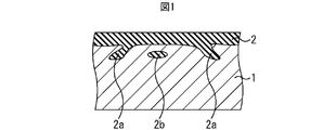
- FIG. 1 is a cross-sectional view showing the structure of a glass coating.
- FIG. 2 is a cross-sectional view showing the aggregated portion of the glass coating.
- FIG. 3 is a cross-sectional view showing a glass coating cavity.
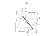
- FIG. 4 is a plan view showing an example of a grain-oriented electrical steel sheet.
- FIG. 5 is a diagram showing a visual field in microscopic observation.
- FIG. 6 is a diagram showing the relationship between the agglomerated portion ratio and the evaluation of the glass coating.
- FIG. 7 is a cross-sectional view showing the destruction of the glass coating.
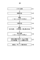
- FIG. 8 is a flowchart showing a method for manufacturing a grain-oriented electrical steel sheet.
- the present inventors paid attention to the relationship between the defect of the glass coating and the structure of the glass coating, and as a result of observing the cross-sectional structure of the glass coating in detail, the glass coating has a wide thickness. It was found that (aggregation part) is present, and the more the aggregation part, the easier the defect occurs. And the knowledge that the defect
- the present inventors have intensively studied a method for producing a grain-oriented electrical steel sheet based on such knowledge. As a result, it has been found that by switching the atmosphere during finish annealing from a mixed gas atmosphere containing hydrogen to a hydrogen gas atmosphere during the temperature rise, the occurrence of agglomerated parts can be suppressed and the loss of the glass coating can be suppressed.
- FIG. 1 is a cross-sectional view showing the structure of a glass coating.
- the glass coating is formed by oxidation of the surface of the steel strip.
- the thickness of the glass coating 2 is not uniform, and the glass coating 2 has an entrance portion (biting portion) 2 a that has entered the surface of the steel strip 1 and the steel strip 1.
- the sizes of the entry portion 2a and the floating portion 2b are various, and there may be a particularly large entry portion 2a as shown in FIG.
- the agglomerated portion of the glass coating is a portion where the thickness is continuously twice or more the average thickness t ave of the glass coating, and the dimension L in the direction parallel to the surface of the steel strip. Means a portion of 3 ⁇ m or more.
- the cavity 3 may exist in the inside of the glass film 2. FIG. In such a case, the thickness of the glass coating 2 is determined assuming that the cavity 3 is also part of the glass coating 2.
- the average thickness of the glass coating 2 is about 0.5 ⁇ m to 2 ⁇ m
- the depth of the entry part 2 a not included in the agglomerated part is about 0.5 ⁇ m to 3 ⁇ m
- the dimension L is about 0.5 ⁇ m to 2 ⁇ m. .
- the reason why the size L of the agglomerated part is set to 3 ⁇ m or more is to distinguish it from the entry part 2a of about 0.5 ⁇ m to 2 ⁇ m.
- the ratio (aggregate part ratio) of the total length of the aggregate part which the said line segment crosses with respect to the length of the said line segment is 0.15 or less.
- FIG. 4 shows a plan view of an example of the grain-oriented electrical steel sheet.
- the ratio of the total length of the portions 6a, 6b, and 6c that the line 10 crosses to the length of the minute 10 (aggregation part ratio) is 0.15 or less.
- the length of the line segment 10 is not particularly limited, there is a variation in the size and localization of the agglomerated portion. Therefore, if the length of the line segment 10 is too short, the influence of the variation may be greatly affected. According to the experience of the present inventors, if the length of the line segment 10 is 500 ⁇ m or more, it can be said that an appropriate statistical result can be obtained with almost no influence of variations. The reason for this numerical limitation will be described later.
- the measuring method of the length of the above-mentioned line segment and the length of the aggregation part is not specifically limited, For example, a sample is cut out from a grain-oriented electrical steel sheet, and these lengths are measured by observation of the section. Can do.
- the inventors prepared samples from eight coil-shaped grain-oriented electrical steel sheets, and determined the relationship between the agglomerated portion ratio and the glass coating defect for each sample. In addition, seven of the eight grain-oriented electrical steel sheets were manufactured by a conventional method, and one was manufactured by a method described later.
- the ratio of the agglomerated part was determined at three places in the width direction and four places in the longitudinal direction. Moreover, about the remaining three, the aggregation part ratio was calculated
- the average value of the evaluation results in Table 1 was calculated for every 0.02 of the aggregate portion ratio. For example, as an evaluation when the agglomerated part ratio is 0.3, an average value of evaluation results in which the agglomerated part ratio is in the range of greater than 0.29 and less than or equal to 0.31 was calculated.
- samples of 10 mm ⁇ 10 mm were prepared from the above-mentioned 105 locations, and the number of defects (a) existing on the surface was counted.
- cross-sectional observation of this sample was performed to determine the agglomerated portion ratio.
- the total length of the agglomerated portion in the range of 500 ⁇ m parallel to the surface of the steel strip was measured.
- the result is shown in FIG.
- the magnetic steel sheet A in FIG. 6 shows the result of the sample produced from the grain-oriented electrical steel sheet manufactured by the conventional method
- the magnetic steel sheet B shows the result of the sample produced from the grain-oriented electrical steel sheet manufactured by the method described later. Show.
- the agglomerated portion ratio As shown in FIG. 6, the smaller the agglomerated portion ratio, the better evaluation was obtained. Further, in the electromagnetic steel sheet B, the agglomerated part ratio exceeded 0.15, whereas in the electromagnetic steel sheet A, the agglomerated part ratio became 0.15 or less. If the aggregate part ratio is 0.15 or less, the evaluation is only good 0 or 1. In addition, particularly good evaluation (0) is easily obtained when the agglomerated portion ratio is 0.1 or less, and when it is 0.09 or less, the evaluation is only 0. Therefore, the agglomerated part ratio is 0.15 or less, preferably 0.1 or less, and particularly preferably 0.09 or less.
- the loss of the glass coating is considered to be caused by the accumulation of nitrogen gas at the interface between the glass coating and the steel strip. Therefore, it is considered that the glass film is more likely to be deficient as there are more portions where nitrogen gas is likely to accumulate.
- cavities 3 as shown in FIG. 3 exist in many glass aggregation portions. From the above, it is considered that the reason why the glass coating defects increase as the aggregate portion ratio increases is because the glass aggregate portion has a structure that easily accumulates nitrogen gas.
- a part of the glass coating 2 may be broken and the steel strip may be exposed.
- the glass film 2 having a thickness corresponding to the agglomerated portion is present in the portion where the glass film 2 is lost, and the thickness of the glass film 2 remaining in the periphery thereof is taken into consideration.
- it may be determined whether or not it corresponds to the aggregation portion. For example, if the dimension L of the missing part is 3 ⁇ m or more, it can be determined that an agglomerated part is present there.
- the dimension L of the missing part is less than 3 ⁇ m, there is a part more than twice the average thickness t ave adjacent to it, and if the sum of these dimensions L is 3 ⁇ m or more, It can be determined that there is an agglomerated part.
- the insulating coating film may be removed by general chemical treatment, and then the sample may be observed.
- the insulating coating film is removed, as shown in FIG. 7, a part of the glass film 2 may be lost. Based on the above-described determination, the presence and size of the agglomerated portion can be determined. .
- FIG. 8 is a flowchart showing a method for manufacturing a grain-oriented electrical steel sheet.
- a slab having a predetermined composition is heated (step S1) to dissolve a substance that functions as an inhibitor.
- step S2 hot rolling is performed to obtain a steel strip (hot rolled steel strip) (step S2).
- fine AlN precipitates are formed.
- the steel strip (hot rolled steel strip) is annealed to form a precipitate (primary inhibitor) such as AlN with an appropriate size and amount (step S3).
- a precipitate such as AlN with an appropriate size and amount (step S3).
- the steel strip (first annealed steel strip) after the annealing in step S3 is cold-rolled (step S4).
- Cold rolling may be performed only once, or multiple times of cold rolling may be performed while intermediate annealing is performed therebetween.
- the primary inhibitor may be formed in the intermediate annealing by omitting the annealing in step S3.
- step S5 the steel strip after cold rolling (cold rolled steel strip) is annealed.
- decarburization is performed, primary recrystallization occurs, and an oxide layer is formed on the surface of the cold-rolled steel strip.
- nitriding treatment is performed on the steel strip (second annealed steel strip) after the annealing in step S5 (step S6). That is, nitrogen is introduced into the steel strip. Examples of the introduction of nitrogen include heat treatment in an atmosphere containing nitrogen gas such as ammonia. In this nitriding treatment, a precipitate (secondary inhibitor) such as AlN is formed. It is desirable that the amount of nitrogen contained in the steel strip after nitriding is 100 ppm or more. This is because the secondary recrystallization (step S7) is appropriately controlled to obtain good magnetic characteristics.
- an annealing separator is applied to the surface of the nitriding steel strip (nitriding steel strip), and then finish annealing is performed (step S7).
- finish annealing is performed (step S7).
- secondary recrystallization occurs, and a glass film (sometimes called a primary film or forsterite film) is formed on the surface of the steel strip.
- FeN and / or MnN may be included in the annealing separator, and nitriding treatment (step S6) may be performed in this final annealing. That is, nitriding treatment may be performed using nitrogen generated by decomposition of FeN and / or MnN.
- various elements may be added to the annealing separator for improving the properties of the glass coating.
- an insulating coating film (sometimes called a secondary film) is formed on the glass film by applying and baking an insulating coating agent (step S8).
- the insulating coating film is formed after the temperature is lowered (cooling process) in the finish annealing (step S7).
- a coating liquid mainly composed of colloidal silica and phosphate is used as the insulating coating agent, it is possible to effectively apply tension to the steel strip, which is effective in further improving iron loss.
- C 0.005 mass% or less
- the C content is preferably 0.005% or less.
- 0.0001 mass% or more may be sufficient as content of C.
- Si 2.0 mass% to 7.0 mass%
- the Si content is desirably 2.0% by mass to 7.0% by mass.
- the remainder of a slab consists of Fe and an unavoidable impurity.
- the glass coating Next, the glass coating will be described. As described above, the aggregation portion ratio in the glass coating is 0.15 or less. Moreover, it is preferable that the aggregation part ratio is 0.10 or less. This is to effectively suppress the loss of the glass coating even when other factors (such as the annealing conditions in step S5 and / or the finishing annealing conditions in step S7) vary.
- the composition of the glass coating is not particularly limited, but the annealing separator used in finish annealing contains, for example, MgO as a main component and contains 90% by mass or more of MgO. For this reason, the glass coating includes, for example, forsterite (Mg 2 SiO 4 ) as a main component and spinel (MgAl 2 O 4 ).
- step S7 finish annealing
- heating is started from a temperature of 850 ° C. or lower, and soaking is performed at 1150 ° C. to 1250 ° C.
- the atmospheric gas is a mixed gas of H 2 gas and N 2 gas, and the ratio of N 2 gas is 20% by volume or more.
- the oxygen potential (P (H 2 O) / P (H 2 )) is set to 0.05 to 0.3.
- P (H 2 O) is a partial pressure of H 2 O
- P (H 2 ) is a partial pressure of H 2 .
- the atmosphere gas is a mixed gas of H 2 gas and N 2 gas, and the ratio of N 2 gas is 20% by volume or more.
- the oxygen potential is not particularly limited.
- the atmosphere gas is changed to an H 2 gas atmosphere at a temperature of 1000 ° C. to 1100 ° C. Soaking is also performed in an H 2 gas atmosphere.
- the reason why the N 2 gas ratio before switching to the H 2 gas atmosphere is set to 20% by volume or more is to suppress denitrification from the steel strip.
- denitrification occurs excessively, the inhibitor in the steel strip becomes insufficient, and the orientation of crystals obtained by secondary recrystallization tends to be disturbed.
- the glass coating also has an effect of suppressing denitrification, but if the temperature is lower than 1000 ° C., this effect is small because the glass coating is not sufficiently formed. Therefore, the ratio of N 2 gas and 20 vol% or more less than 1000 ° C..
- H 2 gas is also necessary. This is to keep the oxygen potential appropriate.
- the oxygen potential tends to affect the oxide layer formed by annealing (step S5).
- the oxygen potential is less than 0.05, the oxide layer becomes thinner due to reduction, so that a glass film is not sufficiently formed. If the oxygen potential exceeds 0.3, the glass coating becomes too thick and easily peels off from the steel strip. Further, the MgO hydrated water during the annealing separation is released into the atmospheric gas as water vapor during the temperature rise. Therefore, does not contain the H 2 gas may be oxygen potential is too high. Accordingly, it is assumed that the atmosphere gas contains H 2 gas at 1000 ° C. or lower. Since it contains H 2 gas in the atmosphere gas, it is desirable that the ratio of N 2 gas is below 75 vol%. If it is 50 volume% or less, it is still more suitable.
- the temperature for switching the atmospheric gas is set to 1000 ° C. or more is that denitrification tends to occur as described above when switching at less than 1000 ° C., and in the oxide layer formed by annealing (step S5). This is because SiO 2 tends to be adversely affected. If it is less than 1000 degreeC, the glass film is not fully formed. For this reason, when the atmospheric gas is switched to the H 2 gas atmosphere in this state, the reducing property of the atmosphere becomes very strong for SiO 2 in the oxide layer. As a result, SiO 2 is adversely affected and it is difficult to form a good glass film. Therefore, the temperature for switching the atmospheric gas is set to 1000 ° C. or higher.
- it is necessary to switch the atmosphere gas at an earlier stage than the completion of the reaction and a higher control effect can be expected by switching at an early stage. . Therefore, in order to obtain a higher effect, it is desirable to switch to the H 2 gas atmosphere in a temperature range of 1000 ° C. or higher and 1050 ° C. or lower.
- a suitable glass film can be obtained after the finish annealing is completed. That is, a glass film having an agglomerated part ratio of 0.15 or less, desirably 0.10 or less is obtained. As a result, it is possible to obtain a grain-oriented electrical steel sheet that suppresses the loss of the glass coating and has good coating properties and magnetic properties.
- composition of the inhibitor is not particularly limited.
- nitrides other than AlN BN, Nb 2 N, Si 3 N 4 etc.
- these two or more types may be contained in the steel strip.
- the production method is not limited to that shown in the flowchart of FIG. 8, and for example, the inhibitor may be formed only once.
- the effect of the present invention becomes more remarkable when the inhibitor is formed twice. This is because the amount of nitrogen gas generated is considered to increase.
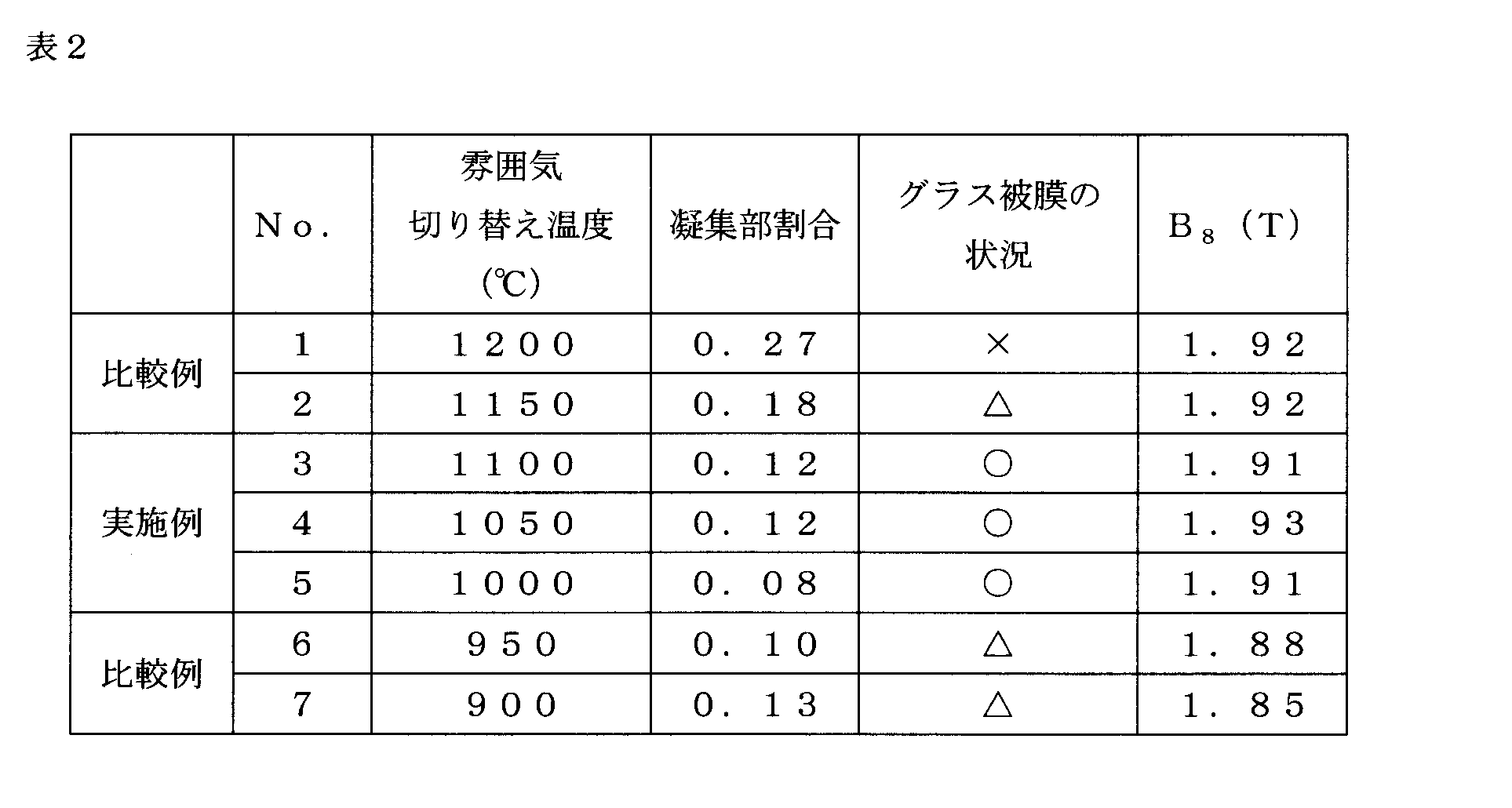
- step S7 an annealing separator containing MgO as a main component was applied and dried, and then the switching temperature to the H 2 gas atmosphere was set as shown in Table 2 and finish annealing was performed (step S7).
- the finish annealing first, the temperature increase was started in an atmosphere of 25% by volume of N 2 gas and the remaining H 2 gas, and the oxygen potential at 850 ° C. or lower was adjusted to 0.1. The temperature rising rate was 15 ° C./h. Then, switching to the middle of the H 2 gas atmosphere at Atsushi Nobori, the temperature was further raised up to 1200 ° C., and held at 1200 ° C. 20 hours. Comparative Example No. In No.
- Example No. 2 As shown in Table 2, in the range of 1000 ° C. or higher, the lower the switching temperature, the lower the agglomerated part ratio. Further, Comparative Example No. in which the switching temperature exceeds the upper limit of the range of the present invention. 1 and no. In No. 2, the ratio of the agglomerated part was particularly high, and many glass coating defects were observed. On the other hand, Example No. 3, no. 4 and no. In No. 5, the aggregate part ratio was 0.15 or less, and a good glass film was obtained.
- Comparative Example No. whose switching temperature is less than the lower limit of the range of the present invention. 6 and no. In No. 7, although the agglomerated part ratio was low, the glass film was thin. Also, lower flux density B 8 when excited at 800A / m. This is presumably because secondary recrystallization became unstable and a good crystal orientation could not be obtained. Incidentally, the magnetic flux density B 8 is a magnetic flux density when excited by 800A / m.
- step S7 finish annealing (step S7) was performed.
- the temperature increase was started in an atmosphere in which the proportion of N 2 gas was 25% by volume and the remainder was H 2 gas.
- the oxygen potential below 850 degreeC was adjusted by the change of the dew point of atmosphere. Comparative Example No. In 14, the temperature increase was started in an N 2 gas atmosphere. The temperature rising rate was 15 ° C./h.
- the ratio of the agglomerated part was high, and many glass coating defects were observed. Moreover, the glass film was thin.
- the ratio of the agglomerated part was low, but the glass film was too thick. This leads to a decrease in the space factor. An abnormal color tone was also observed.
- the present invention can be used, for example, in the electrical steel sheet manufacturing industry and the electrical steel sheet utilizing industry.
Landscapes
- Chemical & Material Sciences (AREA)
- Engineering & Computer Science (AREA)
- Materials Engineering (AREA)
- Mechanical Engineering (AREA)
- Metallurgy (AREA)
- Organic Chemistry (AREA)
- Physics & Mathematics (AREA)
- Chemical Kinetics & Catalysis (AREA)
- Thermal Sciences (AREA)
- Crystallography & Structural Chemistry (AREA)
- Electromagnetism (AREA)
- Manufacturing & Machinery (AREA)
- Manufacturing Of Steel Electrode Plates (AREA)
- Solid-Phase Diffusion Into Metallic Material Surfaces (AREA)
- Soft Magnetic Materials (AREA)
Abstract
Description

次に、上述のような方向性電磁鋼板の製造に好適な方法について説明する。図8は、方向性電磁鋼板の製造方法を示すフローチャートである。
次に、スラブの組成について説明する。
Cの含有量が0.005%を超えていると、磁気時効により磁気特性が劣化しやすい。従って、Cの含有量は0.005%以下とすることが望ましい。一方、Cの含有量を0.0001質量%未満まで低減しても、磁気特性の劣化の抑制の効果はあまり大きなものとならない。このため、Cの含有量は0.0001質量%以上でもよい。
Siの含有量が2.0質量%未満であると、良好な鉄損を得にくい。Siの含有量が7.0質量%を超えていると、冷間圧延(ステップS4)が困難になりやすい。従って、Siの含有量は、2.0質量%~7.0質量%とすることが望ましい。
次に、グラス被膜について説明する。上述のように、グラス被膜における凝集部割合は0.15以下とする。また、凝集部割合は0.10以下であることが好ましい。これは、他の要因(ステップS5の焼鈍の条件及び/又はステップS7の仕上げ焼鈍の条件等)にばらつきがあった場合でも効果的にグラス被膜の欠損を抑制するためである。なお、グラス被膜の組成は特に限定されないが、仕上げ焼鈍の際に用いられる焼鈍分離剤は、例えばMgOを主成分とし、MgOを90質量%以上含有している。このため、グラス被膜は、例えば、フォルステライト(Mg2SiO4)を主成分とし、スピネル(MgAl2O4)を含む。
次に、仕上げ焼鈍について説明する。本発明では、850℃以下の温度から昇温を開始し、1150℃~1250℃で均熱処理を行う。
C:0.05質量%、Si:3.2質量%、Mn:0.09質量%、P:0.02質量%、S:0.006質量%、Al:0.026質量%、N:0.009質量%、及びCr:0.1質量%を含み、残部がFe及び不可避的不純物からなるスラブを溶製した。そして、図8に示すフローチャートに沿って、スラブ加熱(ステップS1)、熱間圧延(ステップS2)、焼鈍(ステップS3)及び冷間圧延(ステップS4)を行った。冷間圧延後の鋼帯の厚さは0.23mmとした。次いで、焼鈍(ステップS5)及び窒化処理(ステップS6)を行い、鋼帯中のC含有量を0.001質量%と、N含有量を0.02質量%とした。続いて、MgOを主成分とする焼鈍分離剤の塗布及び乾燥を行い、その後、H2ガス雰囲気への切り替え温度を表2に示すように設定し、仕上げ焼鈍(ステップS7)を行った。仕上げ焼鈍では、先ず、N2ガスの割合が25体積%、残りがH2ガスの雰囲気で昇温を開始し、850℃以下の酸素ポテンシャルを0.1に調節した。また、昇温速度は15℃/hとした。そして、昇温の途中でH2ガス雰囲気へ切り替え、更に1200℃まで昇温し、1200℃で20時間保持した。なお、比較例No.1では、1200℃でH2ガス雰囲気への切り替えを行い、そのまま1200℃で20時間保持した。そして、20時間の保持後に、室温まで冷却した。次いで、未反応の焼鈍分離剤を除去し、鋼帯及びグラス被膜の評価を行った。この結果を表2に示す。表2中の「グラス被膜の状況」の○は表面観察の結果、1cm2当たりのグラス被膜の欠陥の数が0であり、かつグラス被膜の色調が灰色であったことを示す。△は欠陥の数が1又は0であり、かつグラス被膜が全体的に白っぽくなってグラス被膜が薄かったことを示す。×は欠陥の数が2個以上であったことを示す。
C:0.05質量%、Si:3.2質量%、Mn:0.09質量%、P:0.02質量%、S:0.006質量%、Al:0.026質量%、N:0.009質量%、及びCr:0.1質量%を含み、残部がFe及び不可避的不純物からなるスラブを溶製した。そして、図8に示すフローチャートに沿って、スラブ加熱(ステップS1)、熱間圧延(ステップS2)、焼鈍(ステップS3)及び冷間圧延(ステップS4)を行った。冷間圧延後の鋼帯の厚さは0.23mmとした。次いで、焼鈍(ステップS5)及び窒化処理(ステップS6)を行い、鋼帯中のC含有量を0.001質量%と、N含有量を0.02質量%とした。続いて、MgOを主成分とする焼鈍分離剤の塗布及び乾燥を行い、その後、昇温時の酸素ポテンシャル(P(H2O)/P(H2))を表3に示すように設定し、仕上げ焼鈍(ステップS7)を行った。仕上げ焼鈍では、先ず、N2ガスの割合が25体積%、残りがH2ガスの雰囲気で昇温を開始した。そして、850℃以下の酸素ポテンシャルを雰囲気の露点の変更により調節した。なお、比較例No.14では、N2ガス雰囲気で昇温を開始した。また、昇温速度は15℃/hとした。そして、1050℃でH2ガス雰囲気へ切り替え、更に1200℃まで昇温し、1200℃で20時間保持した。そして、20時間の保持後に、室温まで冷却した。次いで、未反応の焼鈍分離剤を除去し、鋼帯及びグラス被膜の評価を行った。この結果を表3に示す。表3中の「グラス被膜の状況」の○は表面観察の結果、1cm2当たりのグラス被膜の欠陥の数が0であり、かつグラス被膜の色調が灰色であったことを示す。△は欠陥の数が1又は0であり、かつグラス被膜が全体的に白っぽくなってグラス被膜が薄かったことを示す。×は欠陥の数が2個以上であったことを示す。

Claims (9)
- 鋼帯と、
前記鋼帯の表面に形成されたフォルステライト系のグラス被膜と、
を有し、
厚さが連続して前記グラス被膜の平均厚さの2倍以上となっている部分であって、前記鋼帯の表面に平行な方向における寸法が3μm以上の部分を凝集部と定義したとき、
前記鋼帯の表面に平行な任意の線分において、当該線分の長さに対する当該線分が横切る前記凝集部の長さの総計の割合が0.15以下であることを特徴とする方向性電磁鋼板。 - 前記割合が0.10以下であることを特徴とする請求項1に記載の方向性電磁鋼板。
- 前記割合が0.09以下であることを特徴とする請求項1に記載の方向性電磁鋼板。
- 前記鋼帯は、Si:2.0質量%~7.0質量%を含有し、
前記鋼帯中のC含有量は0.005質量%以下であることを特徴とする請求項1に記載の方向性電磁鋼板。 - 前記鋼帯の残部がFe及び不可避的不純物からなることを特徴とする請求項4に記載の方向性電磁鋼板。
- 窒化物を含有することを特徴とする請求項1に記載の方向性電磁鋼板。
- 前記窒化物として、AlN、BN、Nb2N、及びSi3N4からなる群から選択された少なくとも一種を含有することを特徴とする請求項1に記載の方向性電磁鋼板。
- 鋼帯の窒化処理を行う工程と、
次に、焼鈍を行って、鋼帯の表面にフォルステライト系のグラス被膜を形成する工程と、
を有し、
前記焼鈍を行う工程は、
H2ガス及びN2ガスを含み、N2ガスの割合が20体積%以上の混合ガス雰囲気中で昇温を1000℃以上まで行う工程と、
次に、1000℃以上1100℃以下で、雰囲気をH2ガス雰囲気へ切り替える工程と、
を有し、
前記混合ガス雰囲気中での昇温において、850℃以下では、酸素ポテンシャルP(H2O)/P(H2)を0.05~0.3とすることを特徴とする方向性電磁鋼板の製造方法。 - 前記焼鈍において、二次再結晶を生じさせることを特徴とする請求項8に記載の方向性電磁鋼板の製造方法。
Priority Applications (8)
| Application Number | Priority Date | Filing Date | Title |
|---|---|---|---|
| RU2011129615/02A RU2480535C2 (ru) | 2008-12-16 | 2009-09-30 | Лист электротехнической стали с ориентированной зеренной структурой и способ его изготовления |
| EP09833270.3A EP2377961B1 (en) | 2008-12-16 | 2009-09-30 | Grain-oriented electrical steel sheet, and manufacturing method thereof |
| BRPI0923083-1A BRPI0923083B1 (pt) | 2008-12-16 | 2009-09-30 | Method of production of an electric steel sheet with oriented grains |
| US13/127,731 US8920581B2 (en) | 2008-12-16 | 2009-09-30 | Grain-oriented electrical steel sheet and manufacturing method thereof |
| CN2009801506427A CN102257173B (zh) | 2008-12-16 | 2009-09-30 | 方向性电磁钢板及其制造方法 |
| JP2010542908A JP4855540B2 (ja) | 2008-12-16 | 2009-09-30 | 方向性電磁鋼板の製造方法 |
| KR1020117016470A KR101340223B1 (ko) | 2008-12-16 | 2009-09-30 | 방향성 전자기 강판 및 그 제조 방법 |
| PL09833270T PL2377961T3 (pl) | 2008-12-16 | 2009-09-30 | Blacha cienka ze stali elektrotechnicznej o ziarnach zorientowanych i sposób jej wytwarzania |
Applications Claiming Priority (2)
| Application Number | Priority Date | Filing Date | Title |
|---|---|---|---|
| JP2008320109 | 2008-12-16 | ||
| JP2008-320109 | 2008-12-16 |
Publications (1)
| Publication Number | Publication Date |
|---|---|
| WO2010070965A1 true WO2010070965A1 (ja) | 2010-06-24 |
Family
ID=42268640
Family Applications (1)
| Application Number | Title | Priority Date | Filing Date |
|---|---|---|---|
| PCT/JP2009/067017 WO2010070965A1 (ja) | 2008-12-16 | 2009-09-30 | 方向性電磁鋼板及びその製造方法 |
Country Status (9)
| Country | Link |
|---|---|
| US (1) | US8920581B2 (ja) |
| EP (1) | EP2377961B1 (ja) |
| JP (1) | JP4855540B2 (ja) |
| KR (1) | KR101340223B1 (ja) |
| CN (1) | CN102257173B (ja) |
| BR (1) | BRPI0923083B1 (ja) |
| PL (1) | PL2377961T3 (ja) |
| RU (1) | RU2480535C2 (ja) |
| WO (1) | WO2010070965A1 (ja) |
Families Citing this family (6)
| Publication number | Priority date | Publication date | Assignee | Title |
|---|---|---|---|---|
| RU2576355C1 (ru) * | 2011-12-26 | 2016-02-27 | ДжФЕ СТИЛ КОРПОРЕЙШН | Текстурированный лист электротехнической стали |
| WO2014049770A1 (ja) * | 2012-09-27 | 2014-04-03 | Jfeスチール株式会社 | 方向性電磁鋼板の製造方法 |
| JP5780378B1 (ja) * | 2013-09-26 | 2015-09-16 | Jfeスチール株式会社 | 方向性電磁鋼板の製造方法 |
| US10748687B2 (en) * | 2018-03-12 | 2020-08-18 | General Electric Company | Methods of making a component with variable magnetization and related components |
| KR102221606B1 (ko) * | 2018-11-30 | 2021-02-26 | 주식회사 포스코 | 방향성 전기강판 및 그의 제조 방법 |
| RU2771282C1 (ru) * | 2019-01-16 | 2022-04-29 | Ниппон Стил Корпорейшн | Лист электротехнической стали с ориентированной зеренной структурой и способ его изготовления |
Citations (11)
| Publication number | Priority date | Publication date | Assignee | Title |
|---|---|---|---|---|
| JPH05171284A (ja) | 1991-12-17 | 1993-07-09 | Kawasaki Steel Corp | 磁気特性ならびに絶縁皮膜の品質が優れた方向性珪素鋼板の製造方法 |
| JPH0762443A (ja) * | 1993-08-27 | 1995-03-07 | Nippon Steel Corp | 高張力のグラス被膜を有し、磁気特性の優れる方向性電磁鋼板の製造方法 |
| JP2691828B2 (ja) * | 1992-07-02 | 1997-12-17 | 新日本製鐵株式会社 | 磁束密度の極めて高い超低鉄損方向性電磁鋼板の製造方法。 |
| JP2762105B2 (ja) * | 1989-03-25 | 1998-06-04 | 新日本製鐵株式会社 | 鉄損特性の良い高磁束密度一方向性電磁鋼板の製造方法 |
| JPH10245629A (ja) | 1997-03-06 | 1998-09-14 | Nippon Steel Corp | 磁気特性の優れた一方向性電磁鋼板の製造方法 |
| JPH11279644A (ja) * | 1998-03-31 | 1999-10-12 | Kawasaki Steel Corp | 方向性電磁鋼板の製造方法 |
| JP2000063950A (ja) | 1998-08-19 | 2000-02-29 | Kawasaki Steel Corp | 磁気特性および被膜特性に優れた方向性電磁鋼板およびその製造方法 |
| JP3483457B2 (ja) * | 1998-03-09 | 2004-01-06 | 新日本製鐵株式会社 | グラス皮膜と磁気特性に極めて優れた方向性電磁鋼板の製造方法 |
| JP2004211145A (ja) * | 2002-12-27 | 2004-07-29 | Jfe Steel Kk | 低鉄損方向性電磁鋼板の製造方法および仕上焼鈍方法 |
| JP2006161106A (ja) | 2004-12-08 | 2006-06-22 | Nippon Steel Corp | 皮膜欠陥の無い方向性電磁鋼板の製造方法 |
| JP2007238984A (ja) | 2006-03-07 | 2007-09-20 | Nippon Steel Corp | 磁気特性が極めて優れた方向性電磁鋼板の製造方法 |
Family Cites Families (19)
| Publication number | Priority date | Publication date | Assignee | Title |
|---|---|---|---|---|
| JPS535800A (en) * | 1976-07-05 | 1978-01-19 | Kawasaki Steel Co | Highhmagneticcflux density oneeway siliconnsteellfolstellite insulator film and method of formation thereof |
| JPS6475627A (en) * | 1987-09-18 | 1989-03-22 | Nippon Steel Corp | Production of grain oriented electrical steel sheet having extremely high magnetic flux density |
| DE69032461T2 (de) * | 1989-04-14 | 1998-12-03 | Nippon Steel Corp., Tokio/Tokyo | Verfahren zur Herstellung von kornorientierten Elektrostahlblechen mit hervorragenden magnetischen Eigenschaften |
| JPH0756048B2 (ja) * | 1990-11-30 | 1995-06-14 | 川崎製鉄株式会社 | 被膜特性と磁気特性に優れた薄型方向性けい素鋼板の製造方法 |
| JP2674916B2 (ja) * | 1991-12-06 | 1997-11-12 | 新日本製鐵株式会社 | 鏡面高磁束密度方向性珪素鋼板の製造方法 |
| JPH07118743A (ja) * | 1992-03-31 | 1995-05-09 | Nippon Steel Corp | フォルステライト被膜のない高磁束密度方向性珪素鋼板の製造方法 |
| US5507883A (en) | 1992-06-26 | 1996-04-16 | Nippon Steel Corporation | Grain oriented electrical steel sheet having high magnetic flux density and ultra low iron loss and process for production the same |
| RU2124055C1 (ru) * | 1996-08-07 | 1998-12-27 | Научно-производственное предприятие "Эста" | Способ получения форстеритной изоляционной пленки на поверхности анизотропной электротехнической стали |
| US5885371A (en) * | 1996-10-11 | 1999-03-23 | Kawasaki Steel Corporation | Method of producing grain-oriented magnetic steel sheet |
| CN1153227C (zh) | 1996-10-21 | 2004-06-09 | 杰富意钢铁株式会社 | 晶粒取向电磁钢板及其生产方法 |
| BR9800978A (pt) * | 1997-03-26 | 2000-05-16 | Kawasaki Steel Co | Chapas elétricas de aço com grão orientado tendo perda de ferro muito baixa e o processo de produção da mesma |
| KR100351791B1 (ko) * | 1997-04-30 | 2002-11-18 | 가와사키 세이테츠 가부시키가이샤 | 고연성고강도강관및그제조방법 |
| JPH11279642A (ja) * | 1998-03-30 | 1999-10-12 | Nippon Steel Corp | 磁気特性および被膜形成の優れた一方向性電磁鋼板の製造方法 |
| KR19990088437A (ko) * | 1998-05-21 | 1999-12-27 | 에모또 간지 | 철손이매우낮은고자속밀도방향성전자강판및그제조방법 |
| CN1253600C (zh) * | 2000-05-01 | 2006-04-26 | 达泰豪化学工业株式会社 | 氧化镁粒子聚集物 |
| CN1189590C (zh) * | 2000-10-25 | 2005-02-16 | 达泰豪化学工业株式会社 | 氧化镁微粒聚集体 |
| IT1316026B1 (it) * | 2000-12-18 | 2003-03-26 | Acciai Speciali Terni Spa | Procedimento per la fabbricazione di lamierini a grano orientato. |
| KR100586440B1 (ko) * | 2001-07-16 | 2006-06-08 | 신닛뽄세이테쯔 카부시키카이샤 | 고자장 철손과 피막 특성이 우수한 초고자속밀도 일방향성전자강판과 그 제조 방법 |
| RU2298592C2 (ru) * | 2002-03-28 | 2007-05-10 | Ниппон Стил Корпорейшн | Листовая электротехническая сталь с ориентированными зернами, обладающая исключительно высокой адгезией пленки, и способ ее производства |
-
2009
- 2009-09-30 CN CN2009801506427A patent/CN102257173B/zh active Active
- 2009-09-30 BR BRPI0923083-1A patent/BRPI0923083B1/pt active IP Right Grant
- 2009-09-30 US US13/127,731 patent/US8920581B2/en active Active
- 2009-09-30 RU RU2011129615/02A patent/RU2480535C2/ru active
- 2009-09-30 JP JP2010542908A patent/JP4855540B2/ja active Active
- 2009-09-30 PL PL09833270T patent/PL2377961T3/pl unknown
- 2009-09-30 WO PCT/JP2009/067017 patent/WO2010070965A1/ja active Application Filing
- 2009-09-30 KR KR1020117016470A patent/KR101340223B1/ko active IP Right Grant
- 2009-09-30 EP EP09833270.3A patent/EP2377961B1/en active Active
Patent Citations (11)
| Publication number | Priority date | Publication date | Assignee | Title |
|---|---|---|---|---|
| JP2762105B2 (ja) * | 1989-03-25 | 1998-06-04 | 新日本製鐵株式会社 | 鉄損特性の良い高磁束密度一方向性電磁鋼板の製造方法 |
| JPH05171284A (ja) | 1991-12-17 | 1993-07-09 | Kawasaki Steel Corp | 磁気特性ならびに絶縁皮膜の品質が優れた方向性珪素鋼板の製造方法 |
| JP2691828B2 (ja) * | 1992-07-02 | 1997-12-17 | 新日本製鐵株式会社 | 磁束密度の極めて高い超低鉄損方向性電磁鋼板の製造方法。 |
| JPH0762443A (ja) * | 1993-08-27 | 1995-03-07 | Nippon Steel Corp | 高張力のグラス被膜を有し、磁気特性の優れる方向性電磁鋼板の製造方法 |
| JPH10245629A (ja) | 1997-03-06 | 1998-09-14 | Nippon Steel Corp | 磁気特性の優れた一方向性電磁鋼板の製造方法 |
| JP3483457B2 (ja) * | 1998-03-09 | 2004-01-06 | 新日本製鐵株式会社 | グラス皮膜と磁気特性に極めて優れた方向性電磁鋼板の製造方法 |
| JPH11279644A (ja) * | 1998-03-31 | 1999-10-12 | Kawasaki Steel Corp | 方向性電磁鋼板の製造方法 |
| JP2000063950A (ja) | 1998-08-19 | 2000-02-29 | Kawasaki Steel Corp | 磁気特性および被膜特性に優れた方向性電磁鋼板およびその製造方法 |
| JP2004211145A (ja) * | 2002-12-27 | 2004-07-29 | Jfe Steel Kk | 低鉄損方向性電磁鋼板の製造方法および仕上焼鈍方法 |
| JP2006161106A (ja) | 2004-12-08 | 2006-06-22 | Nippon Steel Corp | 皮膜欠陥の無い方向性電磁鋼板の製造方法 |
| JP2007238984A (ja) | 2006-03-07 | 2007-09-20 | Nippon Steel Corp | 磁気特性が極めて優れた方向性電磁鋼板の製造方法 |
Non-Patent Citations (1)
| Title |
|---|
| See also references of EP2377961A4 * |
Also Published As
| Publication number | Publication date |
|---|---|
| CN102257173A (zh) | 2011-11-23 |
| EP2377961A4 (en) | 2017-05-17 |
| CN102257173B (zh) | 2013-12-04 |
| PL2377961T3 (pl) | 2020-11-02 |
| JP4855540B2 (ja) | 2012-01-18 |
| RU2480535C2 (ru) | 2013-04-27 |
| US20110209798A1 (en) | 2011-09-01 |
| JPWO2010070965A1 (ja) | 2012-05-24 |
| US8920581B2 (en) | 2014-12-30 |
| EP2377961B1 (en) | 2020-04-29 |
| RU2011129615A (ru) | 2013-01-27 |
| KR20110095954A (ko) | 2011-08-25 |
| BRPI0923083B1 (pt) | 2017-12-05 |
| EP2377961A1 (en) | 2011-10-19 |
| KR101340223B1 (ko) | 2013-12-10 |
Similar Documents
| Publication | Publication Date | Title |
|---|---|---|
| US7981223B2 (en) | Ultra-high magnetic flux density grain-oriented electrical steel sheet excellent in iron loss at a high magnetic flux density and film properties and method for producing the same | |
| US10208372B2 (en) | Grain-oriented electrical steel sheet and manufacturing method thereof | |
| JP4855540B2 (ja) | 方向性電磁鋼板の製造方法 | |
| JP6610789B2 (ja) | 方向性電磁鋼板用熱延鋼板、および方向性電磁鋼板の製造方法 | |
| US11469017B2 (en) | Grain oriented electrical steel sheet | |
| JP7299511B2 (ja) | 方向性電磁鋼板の製造方法 | |
| JP3240035B2 (ja) | コイル全長にわたり磁気特性に優れた方向性けい素鋼板の製造方法 | |
| JP2020063510A (ja) | 方向性電磁鋼板およびその製造方法 | |
| CN113631734B (zh) | 方向性电磁钢板及其制造方法 | |
| JP7269505B2 (ja) | 方向性電磁鋼板の製造方法 | |
| JP7235058B2 (ja) | 方向性電磁鋼板の製造方法 | |
| EP4174194A1 (en) | Production method for grain-oriented electrical steel sheet | |
| JP7200687B2 (ja) | 方向性電磁鋼板及びその製造方法 | |
| JP7299512B2 (ja) | 方向性電磁鋼板の製造方法 | |
| JP7315857B2 (ja) | 方向性電磁鋼板の製造方法 | |
| JP7265187B2 (ja) | 方向性電磁鋼板およびその製造方法 | |
| US20220025494A1 (en) | Electrical steel sheet and manufacturing method therefor | |
| JP2007177298A (ja) | 方向性電磁鋼板コイルの製造方法 | |
| JP7230930B2 (ja) | 方向性電磁鋼板の製造方法 | |
| RU2805838C1 (ru) | Способ производства листа анизотропной электротехнической стали | |
| JP7269504B2 (ja) | 方向性電磁鋼板の製造方法 | |
| JP7230929B2 (ja) | 方向性電磁鋼板の製造方法 | |
| JP2000096149A (ja) | 被膜特性および磁気特性に優れる方向性けい素鋼板の製造方法 | |
| JP3463417B2 (ja) | 優れた磁気特性が安定して得られる方向性珪素鋼板の製造方法 | |
| US20240229199A9 (en) | Method of manufacturing grain-oriented electrical steel sheet and hot-rolled steel sheet for grain-oriented electrical steel sheet |
Legal Events
| Date | Code | Title | Description |
|---|---|---|---|
| WWE | Wipo information: entry into national phase |
Ref document number: 200980150642.7 Country of ref document: CN |
|
| 121 | Ep: the epo has been informed by wipo that ep was designated in this application |
Ref document number: 09833270 Country of ref document: EP Kind code of ref document: A1 |
|
| WWE | Wipo information: entry into national phase |
Ref document number: 2010542908 Country of ref document: JP |
|
| WWE | Wipo information: entry into national phase |
Ref document number: 13127731 Country of ref document: US |
|
| NENP | Non-entry into the national phase |
Ref country code: DE |
|
| WWE | Wipo information: entry into national phase |
Ref document number: 2009833270 Country of ref document: EP |
|
| ENP | Entry into the national phase |
Ref document number: 20117016470 Country of ref document: KR Kind code of ref document: A |
|
| WWE | Wipo information: entry into national phase |
Ref document number: 5458/DELNP/2011 Country of ref document: IN |
|
| WWE | Wipo information: entry into national phase |
Ref document number: 2011129615 Country of ref document: RU |
|
| ENP | Entry into the national phase |
Ref document number: PI0923083 Country of ref document: BR Kind code of ref document: A2 Effective date: 20110615 |