WO2010067552A1 - ヘッドマウントディスプレイ - Google Patents
ヘッドマウントディスプレイ Download PDFInfo
- Publication number
- WO2010067552A1 WO2010067552A1 PCT/JP2009/006589 JP2009006589W WO2010067552A1 WO 2010067552 A1 WO2010067552 A1 WO 2010067552A1 JP 2009006589 W JP2009006589 W JP 2009006589W WO 2010067552 A1 WO2010067552 A1 WO 2010067552A1
- Authority
- WO
- WIPO (PCT)
- Prior art keywords
- image
- time
- delimiter
- power
- content data
- Prior art date
- Legal status (The legal status is an assumption and is not a legal conclusion. Google has not performed a legal analysis and makes no representation as to the accuracy of the status listed.)
- Ceased
Links
Images




Classifications
-
- G—PHYSICS
- G02—OPTICS
- G02B—OPTICAL ELEMENTS, SYSTEMS OR APPARATUS
- G02B27/00—Optical systems or apparatus not provided for by any of the groups G02B1/00 - G02B26/00, G02B30/00
- G02B27/01—Head-up displays
- G02B27/017—Head mounted
-
- G—PHYSICS
- G02—OPTICS
- G02B—OPTICAL ELEMENTS, SYSTEMS OR APPARATUS
- G02B27/00—Optical systems or apparatus not provided for by any of the groups G02B1/00 - G02B26/00, G02B30/00
- G02B27/01—Head-up displays
- G02B27/0101—Head-up displays characterised by optical features
- G02B2027/014—Head-up displays characterised by optical features comprising information/image processing systems
-
- G—PHYSICS
- G09—EDUCATION; CRYPTOGRAPHY; DISPLAY; ADVERTISING; SEALS
- G09G—ARRANGEMENTS OR CIRCUITS FOR CONTROL OF INDICATING DEVICES USING STATIC MEANS TO PRESENT VARIABLE INFORMATION
- G09G3/00—Control arrangements or circuits, of interest only in connection with visual indicators other than cathode-ray tubes
- G09G3/02—Control arrangements or circuits, of interest only in connection with visual indicators other than cathode-ray tubes by tracing or scanning a light beam on a screen
-
- G—PHYSICS
- G09—EDUCATION; CRYPTOGRAPHY; DISPLAY; ADVERTISING; SEALS
- G09G—ARRANGEMENTS OR CIRCUITS FOR CONTROL OF INDICATING DEVICES USING STATIC MEANS TO PRESENT VARIABLE INFORMATION
- G09G5/00—Control arrangements or circuits for visual indicators common to cathode-ray tube indicators and other visual indicators
- G09G5/02—Control arrangements or circuits for visual indicators common to cathode-ray tube indicators and other visual indicators characterised by the way in which colour is displayed
- G09G5/022—Control arrangements or circuits for visual indicators common to cathode-ray tube indicators and other visual indicators characterised by the way in which colour is displayed using memory planes
-
- G—PHYSICS
- G09—EDUCATION; CRYPTOGRAPHY; DISPLAY; ADVERTISING; SEALS
- G09G—ARRANGEMENTS OR CIRCUITS FOR CONTROL OF INDICATING DEVICES USING STATIC MEANS TO PRESENT VARIABLE INFORMATION
- G09G5/00—Control arrangements or circuits for visual indicators common to cathode-ray tube indicators and other visual indicators
- G09G5/36—Control arrangements or circuits for visual indicators common to cathode-ray tube indicators and other visual indicators characterised by the display of a graphic pattern, e.g. using an all-points-addressable [APA] memory
- G09G5/363—Graphics controllers
Definitions
- the present disclosure relates to a head-mounted display that presents an image indicated by content data to a user's eyes so that the user can recognize the image, and allows the user to recognize the image.
- a technology related to a head-mounted display has been proposed in which an image indicated by content data is presented to a user's eye so that the image can be viewed, and the image is recognized by the user.
- a technology capable of managing the power supplied to the head-mounted display specifically preventing forgetting to turn off the power, after the user has removed the head-mounted display
- a technique for automatically turning off a power supply to a video playback device that provides video to a head-mounted display see, for example, Patent Document 1).
- the head mounted display is used, for example, at the production site of the product.
- a work instruction is presented to a user wearing the head-mounted display and the user assembles a product.
- the user performs the work while wearing the head mounted display, and then starts the next work again for the next work.
- the presentation of an image related to the work instruction is started. While the presentation of the image is stopped, only the transmission of the image is stopped and the black image is presented, so that power is still supplied to each part of the head mounted display.
- the present disclosure provides a new head-mounted display that can appropriately manage the power supplied to the head-mounted display by a method different from the conventional one, specifically, can reduce the power consumption of the head-mounted display.
- the purpose is to provide.
- the head mounted display reproduces content data, detects a break of the content being reproduced when the image obtained by the reproduction is presented from the image presentation unit, and detects a break when content is detected.
- the reproduction of data is stopped and the power supply to the image presentation means is shut off.
- a new head mounted display capable of appropriately managing the power supplied to the head mounted display can be obtained by a method different from the conventional one. Specifically, a head mounted display that can reduce power consumption can be obtained.
- a head-mounted display that presents an image so as to be visible to a user's eye and causes the user to recognize the image, and presents the image to the user's eye.
- Image presenting means control means for reproducing content data, and controlling so that an image obtained by reproduction is presented from the image presenting means, and power management means for managing power supply and interruption to the image presenting means
- detecting means for detecting a break of content indicated by the content data being played back by the control means, wherein the control means detects the break of the content data when the break is detected by the detecting means. Playback is stopped, and the power management means shuts off the power to the image presentation means when the delimiter is detected by the detection means It can be obtained the head-mounted display according to claim and.
- the head-mounted display it is possible to stop the reproduction of the content data at the content break and to cut off the power to the image presentation means for presenting the image obtained by the reproduction of the content data. That is, it is possible to link the stop of the content data and the power interruption to the image presentation means.
- the head-mounted display is not necessarily a single device.
- the head mounted display may be configured by two devices, for example.
- the control unit or the like may be provided in another device, and the head mounted display main body and the control unit or the like may be connected by a predetermined signal cable.
- the time management unit when the delimiter is detected by the detection unit, the time management unit is capable of measuring the passage of time after the delimiter detection, and the power management unit is included in the content data Supply of power to the image presenting means when the passage of time indicated by the time information relating to the time to resume the supply of power when the power to the image presenting means is interrupted is measured by the time measuring means
- the control means obtains a head-mounted display that reproduces the content data from the stopped position when the power supply to the image presentation means is resumed by the power management means. be able to.
- a time measuring unit capable of measuring a lapse of time after the delimiter detection and an identifier capable of identifying the user are acquired.
- An identifier acquisition unit wherein the power management unit associates each identifier of the user with time information regarding a time to resume power supply when power to the image presentation unit is shut off.
- the time information associated with the identifier acquired by the identifier acquisition means can be acquired from the registered table and the passage of time indicated by the time information is measured by the time measurement means.
- the control unit resumes the supply of power.
- the head mounted display when the time associated with each user has elapsed, the power supply to the image presentation means is resumed.
- the content data is reproduced from the stopped position. That is, it is possible to link the supply and cut-off of power to the image presentation means and the reproduction of content data.
- the reproduction of the content data can be started according to the working time of each user, and the working efficiency can be improved.
- an input interface that receives an input of a predetermined command, and a command that acquires the predetermined command input to the input interface when the delimiter is detected by the detection unit Acquisition means, and when the predetermined command is acquired by the command acquisition means, the power management means restarts the supply of power to the image presentation means, and the control means includes the power management means
- a time measuring unit that can measure the passage of time after the delimiter detection, an input interface that receives an input of a predetermined command
- a command acquisition unit that acquires the predetermined command input to the input interface
- an identifier acquisition unit that acquires an identifier that can identify the user
- the command acquisition unit includes the command acquisition unit in the table.
- Registration means for registering, as the time information, the elapsed time measured by the time measuring means at the time when a predetermined command is obtained, in association with the identifier obtained by the identifier obtaining means,
- the management means can acquire time information registered in association with the identifier acquired by the identifier acquisition means from the table, and when the passage of time indicated by the time information is measured by the time measuring means, and
- the predetermined command is acquired by the command acquisition unit, the supply of power to the image presentation unit is resumed, and the control unit resumes the supply of power to the image presentation unit by the power management unit.
- the detection unit can detect delimiter information indicating the delimiter included in the content data reproduced by the control unit, and detects the delimiter information.
- the head mounted display can be obtained by detecting the break. In such a head-mounted display, the number of data to be used can be reduced when performing appropriate processing.
- the detection unit can detect the reproduction of the specific data indicating the specific image included in the content data by the control unit, and detects the reproduction of the specific data.
- the head mounted display can be obtained by detecting the break. In such a head-mounted display, the number of data to be used can be reduced when performing appropriate processing.
- the detection unit reads the delimiter information from delimiter data including delimiter information indicating the delimiter, and detects the delimiter according to the read delimiter information.
- a characteristic head-mounted display can be obtained.
- the delimiter information can be managed by delimiter data different from the content data. For example, this is particularly effective when the content data is existing data that does not include delimiter information.
- a head mounted display characterized in that the head mounted display is a see-through type that transmits external light and can visually recognize an external image.
- an external image can be visually recognized and recognized with the head-mounted display attached.
- the user can alternately perform the task of visually recognizing the content such as work instructions and watching the outside world image while wearing the head-mounted display. it can.
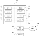
- (A)-(c) is a figure which shows the external appearance of a head mounted display main body. It is a figure which shows a head mounted display. It is a figure which shows the structure of a head mounted display main body. It is a figure which shows the functional block of the control box of a head mounted display. It is a figure which shows the processing flow by the 1st processing form performed in a control box.
- (A) And (b) is a figure which shows the time chart regarding the outline
- (A)-(c) is a figure which shows the division
- a head mounted display main body and a control box that provides an image (hereinafter referred to as “content image”) obtained by executing reproduction processing on content data are connected to the head mounted display main body.
- the head mounted display configured as described above will be described as an example, but these devices can also be configured as an integrated device.
- the head-mounted display body is simply referred to as a head-mounted display (hereinafter referred to as “HMD”).
- the HMD 100 includes temples 104A and 104B, armatures 106A and 106B, and a front frame 108.
- Moderns 102A and 102B that hit the user's ear are attached to one end of the temples 104A and 104B.
- Trillion numbers 112A and 112B are provided at the other ends of the temples 104A and 104B.
- Temples 104A and 104B and Yoroi 106A and 106B are connected via these trillion numbers 112A and 112B.
- the front frame 108 connects the end pieces 106A and 106B.
- a nose pad 110 that contacts the user's nose is attached to the center of the front frame 108.
- the skeleton of the HMD 100 is formed by the temples 104A and 104B, the armatures 106A and 106B, the front frame 108, and the nose pad 110.
- the temples 104A and 104B can be folded at the trillions 112A and 112B formed on the armatures 106A and 106B.
- the structure of the skeleton part of HMD100 is the same as that of normal glasses, for example.
- the HMD 100 is supported on the user's face by the modern 102 ⁇ / b> A and 102 ⁇ / b> B and the nose pad 110 when the HMD 100 is worn on the user.
- drawing of the moderns 102A and 102B and the temples 104A and 104B is omitted.
- the image presentation device 114 is attached to the skeleton part of the HMD 100 via an attachment part 122 disposed near the armor 106A. In a state in which the image presentation device 114 is attached to the vicinity of the armor 106A via the attachment portion 122, the image presentation device 114 is disposed (provided) at a position that is substantially the same height as the left eye 118 of the user wearing the HMD 100.
- the image presentation device 114 is connected to the control box 200 via a predetermined signal cable 250 as shown in FIG. Although details will be described later, the control box 200 performs a rendering process (reproduction process) on the content data stored in the predetermined area.
- the control box 200 controls the input / output interface (hereinafter referred to as “I / F”) 210 provided in the own apparatus shown in FIG. 4 to be described later, and thereby the content image signal including the content image obtained by the rendering process is received. And output to the image presentation device 114 via the signal cable 250.
- the image presentation device 114 receives the content image signal output from the control box 200 via the input / output I / F 650 shown in FIG. 3 described later, and acquires it. Then, the content image based on the content image signal is optically emitted toward the half mirror 116.
- the content images (image lights 120a and 120b) emitted from the image presentation device 114 are reflected by the half mirror 116 and incident on the user's left eye 118, in other words, presented (projected) so as to be visible. Thereby, the user recognizes the content image.
- reference numeral 120a indicates image light relating to the content image emitted from the image presentation device 114
- reference numeral 120b indicates an image that is reflected by the half mirror 116 and is incident on the left eye 118 of the user. Show light.
- the image presentation device 114 scans the image light 120a and 120b in accordance with the acquired content image signal in a two-dimensional direction, and guides the scanned image light 120a and 120b to the user's left eye 118 on the retina.
- a retinal scanning display that forms a content image
- a liquid crystal display an organic EL (Organic Electroluminescence) display, and other devices may be used.
- the HMD 100 is driven by receiving power from the battery 400 connected to the power controller 300 via the power controller 300.
- the HMD 100 includes a control unit 600.
- the control unit 600 includes a CPU 601 that controls the HMD 100, a flash memory 602 as a nonvolatile memory that stores various programs, and a RAM 603 as a work area.
- the CPU 601 receives various signals from the control box 200 and uses the acquired data to execute various programs stored in the flash memory 602 on the RAM 603, thereby configuring various functional units.
- the HMD 100 includes an optical scanning unit 500.
- the optical scanning unit 500 scans the image light (see the image light 120a and 120b shown in FIG. 1) that represents the content image generated based on the image signal supplied from the control unit 600 in a two-dimensional direction, and is scanned.
- the image lights 120a and 120b are guided to the user's left eye 118 to form a content image on the retina.
- the optical scanning unit 500 includes an image light generation unit 720.
- the image light generation unit 720 reads the image signal supplied from the control unit 600 for each dot clock, and generates and emits image light whose intensity is modulated according to the read video signal.
- the collimating optical system 761 collimates the laser beam (image light) generated by the image light generation unit 720 and emitted through the optical fiber 800.
- the horizontal scanning unit 770 functions as a first light scanning unit that reciprocally scans the image light collimated by the collimating optical system 761 in the horizontal direction (first direction) for image display.
- the vertical scanning unit 780 functions as a second optical scanning unit that reciprocally scans the image light scanned in the horizontal direction by the horizontal scanning unit 770 in the vertical direction (second direction substantially orthogonal to the first direction).
- the relay optical system 775 is provided between the horizontal scanning unit 770 and the vertical scanning unit 780.
- the relay optical system 790 emits image light scanned in the horizontal direction and the vertical direction, that is, two-dimensionally scanned, to the pupil Ea.
- the image light generation unit 720 includes a signal processing circuit 721.
- the signal processing circuit 721 receives the content image signal transmitted from the control box 200 and input via the input / output I / F 650 and the control unit 600.
- the signal processing circuit 721 generates each signal that is an element for synthesizing the content image based on the content image signal.
- the signal processing circuit 721 generates and outputs blue (B), green (G), and red (R) image signals 722a to 722c.
- the signal processing circuit 721 outputs a horizontal drive signal 723 used by the horizontal scanning unit 770 and a vertical drive signal 724 used by the vertical scanning unit 780, respectively.
- the image light generation unit 720 includes a light source unit 730 and a light synthesis unit 740.
- the light source unit 730 functions as an image light output unit that converts the three image signals (B, R, G) 722a to 722c output from the signal processing circuit 721 for each dot clock into image light.
- the light combining unit 740 combines these three image lights into one image light in order to generate arbitrary image light.
- the light source unit 730 includes a B laser 734 that generates blue image light and a B laser driver 731 that drives the B laser 734, a G laser 735 that generates green image light, and a G laser driver 732 that drives the G laser 735.
- Each laser 734, 735, 736 can be configured as, for example, a semiconductor laser or a solid-state laser with a harmonic generation mechanism. If a semiconductor laser is used, the drive current can be directly modulated to modulate the intensity of the image light. On the other hand, when a solid-state laser is used, each laser needs to have an external modulator to modulate the intensity of the image light.
- the light combining unit 740 includes collimating optical systems 741, 742, 743, dichroic mirrors 744, 745, 746, and a coupling optical system 747.
- the collimating optical systems 741, 742, and 743 collimate the image light incident from the light source unit 730 into parallel light.
- the dichroic mirrors 744, 745, and 746 combine the collimated image light.
- the coupling optical system 747 guides the combined image light to the optical fiber 800.
- the laser beams emitted from the lasers 734, 735, and 736 are collimated by the collimating optical systems 741, 742, and 743, and then enter the dichroic mirrors 744, 745, and 746. Thereafter, these dichroic mirrors 744, 745, and 746 selectively reflect and transmit each image light with respect to the wavelength.
- the blue image light emitted from the B laser 734 is collimated by the collimating optical system 741 and then incident on the dichroic mirror 744.
- the green image light emitted from the G laser 735 enters the dichroic mirror 745 through the collimating optical system 742.
- the red image light emitted from the R laser 736 is incident on the dichroic mirror 746 through the collimating optical system 743.
- the three primary color image lights incident on the three dichroic mirrors 744, 745, and 746 are reflected or transmitted in a wavelength selective manner, reach the coupling optical system 747, and are collected and output to the optical fiber 800.
- the horizontal scanning unit 770 and the vertical scanning unit 780 scan in the horizontal direction and the vertical direction to obtain scanned image light so that the image light incident from the optical fiber 800 can be projected as an image.
- the horizontal scanning unit 770 includes a resonance type deflection element 771, a horizontal scanning control circuit 772, and a horizontal scanning angle detection circuit 773.
- the resonant deflection element 771 has a reflection surface for scanning image light in the horizontal direction.
- the horizontal scanning control circuit 772 functions as a drive signal generator that resonates the resonance type deflection element 771 and generates a drive signal that swings the reflection surface of the resonance type deflection element 771.
- the horizontal scanning angle detection circuit 773 detects a swing state such as a swing range and a swing frequency of the reflection surface of the resonant deflection element 771 based on the displacement signal output from the resonant deflection element 771.
- the horizontal scanning angle detection circuit 773 inputs a signal indicating the detected oscillation state of the resonance type deflection element 771 to the control unit 600.
- the vertical scanning unit 780 includes a deflection element 781, a vertical scanning control circuit 782, and a vertical scanning angle detection circuit 783.
- the deflection element 781 scans the image light in the vertical direction.
- the vertical scanning control circuit 782 drives the deflection element 781.
- the vertical scanning angle detection circuit 783 detects a swing state such as a swing range and a swing frequency of the reflecting surface.
- the horizontal scanning control circuit 772 and the vertical scanning control circuit 782 are driven based on the horizontal driving signal 723 and the vertical driving signal 724 output from the signal processing circuit 721, respectively.
- the vertical scanning angle detection circuit 783 inputs a signal indicating the detected swing state of the deflection element 781 to the control unit 600.
- the control unit 600 adjusts the horizontal drive signal 723 and the vertical drive signal 724 by controlling the operation of the signal processing circuit 721. By this adjustment, the control unit 600 adjusts the luminance of the image to be displayed by causing the horizontal scanning unit 770 and the vertical scanning unit 780 to change the scanning angle of the image light.
- the scanning angle thus changed is detected by the control unit 600 based on detection signals from the horizontal scanning angle detection circuit 773 and the vertical scanning angle detection circuit 783.
- the detection result of the scanning angle by the control unit 600 is fed back to the horizontal drive signal 723 through the signal processing circuit 721 and the horizontal scanning control circuit 772, and is also vertically transmitted through the signal processing circuit 721 and the vertical scanning control circuit 782. This is fed back to the drive signal 724.
- the relay optical system 775 relays image light between the horizontal scanning unit 770 and the vertical scanning unit 780.
- the light scanned in the horizontal direction by the resonant deflection element 771 is converged on the reflection surface of the deflection element 781 by the relay optical system 775, scanned in the vertical direction by the deflection element 781, and scanned in two dimensions.
- Light is emitted to the relay optical system 790.
- the relay optical system 790 includes lens systems 791 and 794 having positive refractive power.
- the scanning image light for display emitted from the vertical scanning unit 780 is converted into convergent image light by the lens system 791 so that each image light has the center lines of the image light substantially parallel to each other.
- the lens system 794 converts the image light into substantially parallel image light, and the center line of the image light is converted so as to converge on the pupil Ea of the observer.
- the image light incident from the optical fiber 800 is scanned in the horizontal direction by the horizontal scanning unit 770 and then scanned in the vertical direction by the vertical scanning unit 780.
- the arrangement of the horizontal scanning unit 770 and the vertical scanning unit 780 may be exchanged so that image light is scanned in the vertical direction by the vertical scanning unit 780 and then scanned in the horizontal direction by the horizontal scanning unit 770.
- control box configuration For example, the control box 200 is attached to a user's waist or the like.
- the control box 200 includes a CPU 202 that controls the device itself, a ROM 204 that stores various programs, a RAM 206 as a work area, a storage unit 208 that stores content data 2082, an HMD 100, and An input / output I / F 210 that transmits and receives various signals to and from the power controller 300 that supplies and shuts off power to the control box 200, and an operation unit that is operated by the user and receives instructions from the user 212 and a timer 214 capable of measuring the passage of time.
- the storage unit 208 is constituted by, for example, a hard disk.
- the content data 2082 stored in the storage unit 208 includes, for example, a work instruction describing a method for assembling a predetermined product.
- the operation unit 212 includes, for example, a key, and receives, for example, instructions to start and end playback of the content data 2082.
- the CPU 202 acquires a content image by executing a program for reproducing (rendering) the content data 2082 stored in the ROM 204 on the RAM 206. Then, the CPU 202 executes a program for controlling the input / output I / F 210 stored in the ROM 204 on the RAM 206 and outputs a content image signal including the content image from the input / output I / F 210 to the HMD 100. Further, the CPU 202 executes a program for controlling the power controller 300 stored in the ROM 204 on the RAM 206 based on the delimiter information related to the delimiter of the content being reproduced, whereby the power supply to the HMD 100 by the power controller 300 is performed.
- the CPU 202 executes a program for controlling the HMD 100 stored in the ROM 204 on the RAM 206, and controls the operation of the HMD 100 instructed by the operation unit 212 and the operation of the HMD 100 based on the delimiter information. . Therefore, the CPU 202 uses various data such as the content data 2082 and executes various programs stored in the ROM 204 on the RAM 206, so that various functional units (for example, control unit, power management unit, detection unit) are configured.
- various functional units for example, control unit, power management unit, detection unit
- the first processing mode is a processing mode executed when the content data 2082 itself includes delimiter information indicating the delimiter of the content indicated by the content data 2082.
- the content data 2082 will be described as moving image data.
- the content data 2082 includes delimiter information indicating the delimiter of the content indicated by the content data 2082 as header information.
- the CPU 202 determines whether or not an instruction to reproduce specific content stored in the storage unit 208 (execution of reproduction processing for the content data 2082) is given via the operation unit 212 of the control box 200 (S100). ). As a result of the determination, if reproduction is not instructed (S100: No), the CPU 202 waits until a reproduction instruction is input via the operation unit 212. On the other hand, when the user gives a reproduction instruction via the operation unit 212 (S100: Yes), the CPU 202 reads the content data 2082 from the storage unit 208 onto the RAM 206, and reproduces the content data 2082 read into the RAM 206. The process is started (executed) (S102). Specifically, the CPU 202 renders the content data 2082, generates a content image, and outputs a content image signal including the content image from the input / output I / F 210 to the HMD 100.
- the image presentation device 114 of the HMD 100 receives the content image signal output from the control box 200 via the input / output I / F 650 shown in FIG. 3 and acquires it. Then, the content image based on the content image signal is optically emitted toward the half mirror 116. The content image (image light) emitted from the image presentation device 114 is reflected by the half mirror 116 and is incident on the user's left eye 118 (see FIG. 1), in other words, presented (projected) so as to be visible. The Thereby, the user recognizes the content image.
- the CPU 202 executing the reproduction process determines whether or not the reproduction of the content data 2082 has ended, in other words, whether or not the reproduction has been performed up to the end position of the content data 2082 (reproduction to the end) (S104). As a result of the determination, when the reproduction has been performed up to the end position (S104: Yes), the CPU 202 reads out the program for controlling the power controller 300 stored in the ROM 204 onto the RAM 206, and executes this to execute the program by the power controller 300. The supply of power to the HMD 100 is interrupted, and this process is terminated. On the other hand, when it is determined that the playback has not been performed to the end position (S104: No), the CPU 202 shifts the process to S106.
- the CPU 202 determines whether or not a content break indicated by the content data 2082 has been detected based on the break information included as the header information of the content data 2082. Specifically, the CPU 202 determines whether or not the reproduction has been completed up to the portion indicated by the delimiter information. As a result of the determination, if no delimiter is detected (S106: No), the CPU 202 shifts the process to S104 and continuously executes the reproduction process of the content data 2082. On the other hand, when a break is detected (S106: Yes), the CPU 202 shifts the process to S108.
- the CPU 202 reads a program for controlling the power supply controller 300 stored in the ROM 204 onto the RAM 206, and executes it. Thereby, the CPU 202 cuts off the supply of power to the HMD 100 by the power supply controller 300, more specifically, the supply of power to the image presentation device 114.
- the CPU 202 stops the reproduction process of the content data 2082 and stores the stopped position (position where the reproduction process is completed) in the RAM 206. Note that the CPU 202 starts measuring the passage of time after detection by the timer 214 on the condition that a break is detected.
- the CPU 202 that has started measuring the passage of time after the detection of the break stops the playback processing of the content data 2082, specifically the time related to the resumption of playback included in the content data 2082 in association with the break detected in S 106. In other words, it is determined whether or not the designated time indicated by the time information related to the time from the interruption of the power supply to the image presentation device 114 until the resupply has elapsed (S110). As a result of the determination, if the specified time has not elapsed (S110: No), the CPU 202 waits until the specified time elapses.
- the CPU 202 executes a program for controlling the power supply controller 300 stored in the ROM 204 on the RAM 206, and the power supply controller 300 applies the program to the image presentation device 114.
- the supply of power is resumed (S112).
- the CPU 202 shifts the process to S102, and resumes the reproduction process of the content data 2082 from the position where the reproduction process stored in the RAM 206 in S108 is stopped.
- the CPU 202 when the CPU 202 detects a break (S106: Yes), the CPU 202 has described the configuration for cutting off the power supply to the image presentation device 114. However, the configuration for cutting off the power supply to the entire HMD 100 is described. It can also be. In other words, the power supply to the image presentation device 114 and a predetermined configuration constituting the control box 200 can be cut off. Further, for example, it may be configured to determine whether to cut off the power supply to the image presentation device 114 or to cut off the power supply to the HMD 100 according to the remaining amount of the battery 400.
- the CPU 202 when the remaining amount of the battery 400 is greater than a predetermined remaining amount, the CPU 202 does not cut off the power supply to the image presentation device 114, and when the remaining amount is low, the CPU 202 cuts off the power supply to the HMD 100. It can also be set as such. According to this, it is possible to achieve both reduction in time required for restart and long-time driving of the HMD 100.
- the content data 2082 is content including 10 minutes of moving image data as a whole regarding a work instruction regarding assembly of a predetermined product.
- the content data body constituting the content data 2082 includes a first step (length: 3 minutes) and a second step (length: 4 minutes) for assembling a predetermined product. ) And the third step (length: 3 minutes). Then, first delimiter information is set as a delimiter between the first step and the second step, and second delimiter information is set as a delimiter between the second step and the third step.
- the content data 2082 is associated with each of the first delimiter information and the second delimiter information, and the time information indicating each of the specified times described above is used as header information. Including.
- the designated time (time information) can employ a configuration that can be arbitrarily set by a user or the like.
- the reproduction processing of the content data 2082 is started.
- the By starting the reproduction process a content image related to the first step is presented from the image presentation device 114 (see FIG. 1) to the user wearing the HMD 100. In other words, the user starts viewing the content image related to the first step obtained by reproduction.
- the CPU 202 detects the first delimiter information set as the header information (see S106: Yes in FIG. 5)
- the CPU 202 stops the reproduction processing of the content data 2082, controls the power controller 300,
- the power supply to the presentation device 114 is cut off (see S108 in FIG. 5). Further, the CPU 202 measures the elapsed time after the detection using the timer 214 on the condition that the first delimiter information is detected.
- the user performs the first step based on the information obtained from the content image related to the first step that was viewed earlier. That is, the designated time corresponding to the first delimiter information is set in advance according to the time required for the user to perform the first step.
- the user performs the assembly work of the product according to the first process based on the information obtained by viewing during the designated time corresponding to the first delimiter information.
- the user visually recognizes the outside world through the half mirror 116 with the HMD 100 mounted. Specifically, with the HMD 100 mounted, the user visually recognizes the product (part) to be assembled at hand with the left eye 118 (see FIG. 1) through the half mirror 116 and performs the assembly work. To do.
- the CPU 202 controls the power supply controller 300 again under the condition that the elapsed time of the designated time corresponding to the first delimiter information is measured by the timer 214 (see S110: Yes in FIG. 5), and the power supply to the image presentation device 114 Is resumed (see S112 in FIG. 5), and the reproduction process from the portion related to the second step of the content data body is resumed (S102 in FIG. 5).
- a content image related to the second step is presented from the image presentation device 114 to the user wearing the HMD 100. In other words, the user starts viewing the content image related to the second step obtained by reproduction.
- the CPU 202 detects the second delimiter information (detects the second delimiter information set in the header 7 minutes after the top of the content data main body, see S106 in FIG. 5: Yes)
- the CPU 202 The reproduction process 2082 is stopped again, the power controller 300 is controlled, and the power supply to the image presentation device 114 is shut off (see S108 in FIG. 5).
- the CPU 202 measures the elapsed time after the detection using the timer 214 on the condition that the second delimiter information is detected.
- the user performs the assembly work of the product related to the second process based on the information obtained from the content image related to the second process viewed earlier. That is, like the specified time corresponding to the first delimiter information, the specified time corresponding to the second delimiter information is set in advance according to the time required for the user to perform the second step.
- the CPU 202 controls the power supply controller 300 again on the condition that the designated time corresponding to the second delimiter information is measured by the timer 214 (see S110: Yes in FIG. 5), and supplies power to the image presentation device 114 again. Is resumed (see S112 in FIG. 5), and the reproduction process from the portion related to the third step of the content data body is resumed (S102 in FIG. 5). As a result, a content image related to the third step is presented from the image presentation device 114 to the user wearing the HMD 100. In other words, the user starts viewing the content image related to the third step obtained by reproduction. Thereafter, when the CPU 202 plays back to the end position of the content data 2082 (see S104 in FIG.
- the CPU 202 stops the playback processing of the content data 2082, controls the power controller 300, and shuts off the power supply to the image presentation device 114. To do. Then, the CPU 202 ends this process. The user performs product assembly work related to the third process based on the information obtained in the content image related to the third process viewed earlier, thereby completing the assembly of the predetermined product.
- Content delimiters are detected based on delimiter information included in the content data 2082 as header information (S106 in FIG. 5), and on the condition that they are detected (S106: Yes in FIG. 5), playback processing by the CPU 202 is stopped. Then, the power supply supplied from the battery 400 to the image presentation device 114 is shut off (S108 in FIG. 5). According to this, in a state where no content image is presented to the user, based on the above example, the power consumption of the HMD 100 is reduced in a state where the user wearing the HMD 100 is assembling a predetermined product. It is possible to realize long-time driving by the battery 400. For example, this is particularly effective when content is viewed intermittently or intermittently by battery driving.
- the power of the image presentation device 114 is cut off, it is possible to easily see the outside world through the half mirror 116, and ensure the same level of view as when the HMD 100 is not worn. Can do. Furthermore, the user does not need to perform a special operation in order to realize the above-described operation, and the operation burden on the user can be reduced in this respect.
- the delimiter information indicating the delimiter of the content indicated by the content data 2082 and the time information (designated time) corresponding to the delimiter information are included as header information of the content data 2082.
- the delimiter information and time information are included in a delimiter table different from the content data 2082.
- the content data body (which constitutes the content data 2082 together with the header information) which is the body portion of the content data 2082 includes time stamp information.
- the time stamp information indicates the position (elapsed time) from the beginning of the content data body, and when the content data 2082 is reproduced, the position being reproduced can be specified by the time stamp information.
- the second processing mode is different from the first processing mode in this point, but the configuration is otherwise the same. In the following description, differences will be mainly described, and other common points will be described with respect to the correspondence with the first processing mode, and details will be omitted.
- the partition table may be stored in an area accessible by the control box 200. In the following description, it is assumed that it is stored in the storage unit 208.
- the CPU 202 that has started this process first executes S200.
- S200 is processing corresponding to S100 (see FIG. 5) of the first processing form, and the CPU 202 executes the above-described processing, and when the determination of S200 is affirmed (S200: Yes), the processing is performed.
- the process proceeds to S202.
- the CPU 202 reads out a delimiter table corresponding to the content data 2082 stored in the storage unit 208 and read out in S200 on the RAM 206.
- delimiter information indicating delimiters of the content data 2082 and time information associated with the delimiter information are registered in the delimiter table.
- the content data 2082 will be described in detail with reference to FIG. 6A described above.
- the delimiter table includes first delimiter information (3 minutes) indicating delimiters of the first process and the second process, and the working time of the first process.
- Time information (60 minutes; hereinafter referred to as “first time information”) is associated with the second step information (7 minutes) indicating the second step and the third step, and the second step.
- Time information (60 minutes, hereinafter referred to as “second time information”) is registered in association with each other.
- each of S204 to S214 is a process corresponding to each of S102 to S112 of the first processing form shown in FIG. CPU202 performs each process mentioned above, and complete
- the CPU 202 determines whether or not the reproduction processing up to the content delimiter has been executed based on the first delimiter information and the second delimiter information acquired in the RAM 206 in S202 and the time stamp information of the content data 2082.
- the CPU 202 detects the elapse of 3 minutes corresponding to the first delimiter information based on the time stamp information of the content data body, the CPU 202 affirms the determination in S208 (S208: Yes). Similarly, if the CPU 202 detects the elapse of 7 minutes corresponding to the second delimiter information, the determination in S208 is affirmed (S208: Yes). Note that the time chart when the processing of FIG. 7 is executed is the same as that of the first processing mode described above (see FIG. 6B), and thus the description thereof is omitted.
- a configuration is adopted in which the delimiter information and the time information are registered in a delimiter table that is different from the content data 2082 (FIG. 8), and the CPU 202 acquires the delimiter information and the time information from this delimiter table (S202 in FIG. 7).
- the third processing form is common to the second processing form in that a partition table is used.
- the third processing form identifies the user wearing the HMD 100 and sets the time information according to the user, and in the registration form of the time information in the partition table, the second process A configuration different from the form is adopted. Therefore, in the following description, it demonstrates centering on the point which is different from these 2nd processing forms, about the other common point, a corresponding relationship with a 2nd processing form is demonstrated and the detail is abbreviate
- the delimiter table in the third processing form is stored in the storage unit 208 for each user who wears the HMD 100.
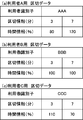
- the identifier “AAA” for identifying the user A, the first division information and the second division information, the first time information and the second time information are associated with each other. be registered.
- the third processing mode adopts a mode different from the second processing mode. That is, in the third processing mode, the basic time information is stored in the storage unit 208 in association with the delimiter table, and the ratio to the basic time information is registered as the delimiter table.
- the first processing time “60 minutes” and the second processing time “60 minutes” are stored as basic time information, and the ratios of the first processing time and the second processing time are registered in the partition table.
- the first time information “80%” is registered in association with the first delimiter information “3 minutes”.
- the CPU 202 controls the power supply controller 300 after 48 minutes (calculated by the product of the basic time information and the first time information) after detecting the first delimiter information, and supplies power to the image presentation device 114. To resume.
- second time information “120%” is registered in association with the second delimiter information “7 minutes”.
- the CPU 202 resumes the supply of power to the image presentation device 114 after 72 minutes (the calculation method is the same as the first time information).
- the registration of the first time information and the second time information is the same as that in FIG.
- the partition table of FIG. 9B is stored in the storage unit 208 for the user B, and the partition table of FIG.
- the manner of registration in these partition tables is the same as in FIG. 9A, and the description thereof is omitted.
- the CPU 202 determines whether or not the reproduction of specific content stored in the storage unit 208 (execution of reproduction processing for the content data 2082) is instructed via the operation unit 212 of the control box 200. (S300). As a result of the determination, if reproduction is not instructed (S300: No), the CPU 202 waits until a reproduction instruction is input via the operation unit 212. On the other hand, when the user instructs reproduction via the operation unit 212 (S300: Yes), the CPU 202 shifts the processing to S302.
- the CPU 202 sends, together with the reproduction instruction, the identification information of the user who has input the reproduction instruction, for example, from an IC card carried by the user via an identifier acquisition unit not drawn in FIG. Obtained on the RAM 206. For example, when the user C has instructed reproduction, the CPU 202 acquires identification information “CCC” for identifying the user C.
- the CPU 202 reads the partition table including the acquired identification information and the basic time information from the storage unit 208. For example, when the identification information “CCC” has been acquired in S300, the CPU 202 reads the delimiter table illustrated in FIG. 9C stored in the storage unit 208. The CPU 202 acquires the first break information and the first time information and the second break information and the second time information registered in the break table shown in FIG. Then, the CPU 202 executes each process of S304 to S310, and shifts the process to S312.
- each process of S304 to S310 is a process (see S102 to S108 of the first process form shown in FIG. 5) corresponding to each process of S204 to S210 (see FIG.
- the process of S308 includes the user delimiter table acquired in S302. Based on the above example, the first delimiter information and the second delimiter information registered in the delimiter table of user C and the time of the content data 2082 It is executed based on the stamp information.
- the CPU 202 calculates and acquires the resumption timing of the power supply to the image presentation device 114.
- the specific calculation method is as described in the description of FIG.
- the CPU 202 determines whether or not an instruction to resume playback is input via the operation unit of the control box 200 (S314).
- the reproduction restart operation is preferable in the following points.
- the user C performs the first step based on the viewing of the content image related to the first step after detecting the first break information, it is indicated by the first time information set in the break table shown in FIG. 9C.
- the designated time of the first step is 42 minutes (basic time information 60 minutes ⁇ time information 0.7 (70%)).
- the work may be completed in 40 minutes.
- the configuration in which the resumption of reproduction can be designated enables viewing of the content image related to the next second step on the condition that the work is completed, and allows the product assembly work to proceed efficiently.
- S314 If an instruction to resume playback is input in S314 (S314: Yes), the CPU 202 shifts the process to S318. On the other hand, if an instruction to resume playback has not been input (S314: No), the CPU 202 determines whether the designated time calculated based on the basic time information and the first time information or the second time information has elapsed in S312. It is determined whether or not (S316). Here, S316 is processing corresponding to S212 of the second processing mode shown in FIG. 7 (S110 of the first processing mode shown in FIG. 5), and description thereof is omitted. If the specified time has elapsed (S316: Yes), the CPU 202 shifts the process to S318.
- the CPU 202 sets the first time information or the second time information registered in the break table to the ratio of the time from the detection of the break information to the determination of the restart of playback with respect to the time indicated by the basic time information.
- Update (save overwriting). More specifically, when the resumption of reproduction is instructed in S314 (S314: Yes), the CPU 202 determines the ratio of the time from the detection of the break information to the input of the resumption instruction of reproduction with respect to the time indicated by the basic time information. Update and register as new time information. For example, if the user C finishes the assembly work related to the first process in 36 minutes and inputs an instruction to resume playback at that time, the CPU 202 registers the first process registered in the partition table for user C. 1 hour information is updated to “60%”. If the specified time has elapsed (S316: Yes), the CPU 202 overwrites the same value as the current registration. In this case, it is possible to adopt a configuration in which updating by overwriting is not performed.
- S320 is processing corresponding to S214 of the second processing mode shown in FIG. 7 (S112 of the first processing mode shown in FIG. 5), and a description thereof will be omitted. Note that the time chart when the process of FIG. 10 is executed (see FIG. 6B) is the same as that of the first processing mode described above, and thus the description thereof is omitted.
- a partition table (FIG. 9) is provided for each user wearing the HMD 100, and this partition table is stored in the storage unit 208 together with basic time information.
- the CPU 202 acquires user identification information together with a content reproduction instruction (S300 in FIG. 10).
- the CPU 202 calculates the specified time from the detection of the content break (S308: Yes in FIG. 10) to the restart of the power supply to the image presentation device 114 based on the obtained break table and basic time information. (S312 in FIG. 10). According to this, it is possible to set an appropriate designated time for each user. Based on the above-described example, it is possible to set the resumption of power supply to the image presentation device 114 and the resumption of presentation of the content image according to the skill level of the user's assembly work.
- the measurement start of the specified time which is a condition for restarting the supply of power to the image presentation device 114, is the time when the break information is detected.
- the measurement may be started on the condition that the reproduction processing for the content data 2082 is stopped or the power to the image presentation device 114 is shut off.
- the CPU 202 When the user instructs the reproduction of specific content stored in the storage unit 208 via the operation unit 212 of the control box 200, that is, the execution of the reproduction process for the content data 2082 (S100: Yes), the CPU 202 The content data 2082 is read out from the storage unit 208 onto the RAM 206. The CPU 202 executes a reproduction process on the content data 2082 read into the RAM 206 (S102), thereby generating a content image.
Landscapes
- Physics & Mathematics (AREA)
- General Physics & Mathematics (AREA)
- Optics & Photonics (AREA)
- Controls And Circuits For Display Device (AREA)
- Control Of Indicators Other Than Cathode Ray Tubes (AREA)
Abstract
利用者の眼に、画像を提示する画像提示手段と、コンテンツデータを再生し、再生によって得られた画像が画像提示手段から提示されるよう制御する制御手段と、画像提示手段への電源の供給及び遮断を管理する電源管理手段と、制御手段により再生されているコンテンツデータによって示されるコンテンツの区切りを検出する検出手段と、を備えるヘッドマウントディスプレイである。検出手段により区切りが検出された場合(S106:Yes)、制御手段はコンテンツデータの再生を停止し、電源管理手段は画像提示手段への電源を遮断する(S108)。
Description
本開示は、利用者の眼にコンテンツデータにより示される画像を視認可能に提示し、この利用者に画像を認識させるヘッドマウントディスプレイに関するものである。
利用者の眼にコンテンツデータにより示される画像を視認可能に提示し、この利用者に画像を認識させるヘッドマウントディスプレイに関する技術が提案されている。例えば、ヘッドマウントディスプレイに供給される電源を管理、具体的には、電源の切り忘れを防止可能な技術として、利用者が、ヘッドマウントディスプレイを外した後、所定時間経過後に、ヘッドマウントディスプレイと、ヘッドマウントディスプレイに対して映像を提供する映像再生装置との電源を自動的にオフとする技術が提案されている(例えば、特許文献1参照)。
ところで、ヘッドマウントディスプレイを、例えば、製品の生産現場において使用することが想定される。具体的には、ヘッドマウントディスプレイを用いて作業指示を、これを装着する利用者に提示し、この利用者が、製品を組み立てるような場合が想定される。このような用途の場合、画像の提示が停止されたとしても、利用者は、ヘッドマウントディスプレイを装着したまま作業を行い、その後、次の作業を開始するにあたり、再度、次の作業のための作業指図に関する画像の提示を開始すると考えられる。画像の提示が停止されている間は画像の送信のみが停止されており黒色の画像が提示されているので、ヘッドマウントディスプレイ各部に電源が供給されたままとなっている。
本開示は、従来とは異なる手法によって、ヘッドマウントディスプレイに供給される電源の管理を適切に行い得る、具体的には、ヘッドマウントディスプレイの電力消費を低減することができる、新たなヘッドマウントディスプレイを提供することを目的とする。
本開示のヘッドマウントディスプレイは、コンテンツデータを再生し、再生によって得られた画像が画像提示手段から提示される場合に、再生されているコンテンツの区切りを検出し、区切りが検出された場合、コンテンツデータの再生を停止するとともに、画像提示手段への電源を遮断することとしたものである。
本開示のヘッドマウントディスプレイによれば、従来とは異なる手法によって、ヘッドマウントディスプレイに供給される電源の管理を適切に行い得る、新たなヘッドマウントディスプレイを得ることができる。具体的には、電力消費量を低減することができるヘッドマウントディスプレイを得ることができる。
本開示の一側面によれば、利用者の眼に視認可能に画像を提示し、前記利用者に前記画像を認識させるヘッドマウントディスプレイであって、前記利用者の眼に、前記画像を提示する画像提示手段と、コンテンツデータを再生し、再生によって得られた画像が前記画像提示手段から提示されるよう制御する制御手段と、前記画像提示手段への電源の供給及び遮断を管理する電源管理手段と、前記制御手段により再生されている前記コンテンツデータによって示されるコンテンツの区切りを検出する検出手段と、を備え、前記制御手段は、前記検出手段により前記区切りが検出された場合、前記コンテンツデータの再生を停止し、前記電源管理手段は、前記検出手段により前記区切りが検出された場合、前記画像提示手段への電源を遮断することを特徴とするヘッドマウントディスプレイを得ることができる。
このようなヘッドマウントディスプレイでは、コンテンツの区切りでコンテンツデータの再生を停止し、コンテンツデータの再生によって得られた画像を提示する画像提示手段への電源を遮断することができる。すなわち、コンテンツデータの停止と、画像提示手段への電源の遮断とを連動させることができる。なお、ヘッドマウントディスプレイは、必ずしも1つの装置である必要はない。ヘッドマウントディスプレイは、例えば、2つの装置による構成であってもよい。例えば、制御手段等が別の装置に備えられ、ヘッドマウントディスプレイ本体と制御手段等とが、所定の信号ケーブルで接続されてもよい。
本開示の他の側面によれば、前記検出手段により前記区切りが検出された場合、前記区切り検出後の時間の経過を計測可能な計時手段を備え、前記電源管理手段は、前記コンテンツデータに含まれる前記画像提示手段への電源が遮断された場合において電源の供給を再開する時間に関する時間情報によって示される時間の経過が、前記計時手段により計測された場合、前記画像提示手段への電源の供給を再開し、前記制御手段は、前記電源管理手段により前記画像提示手段への電源の供給が再開された場合、前記コンテンツデータを、停止した位置から再生することを特徴とするヘッドマウントディスプレイを得ることができる。
このようなヘッドマウントディスプレイでは、時間情報によって示される時間が経過した場合、画像提示手段への電源供給が再開される。コンテンツデータは、停止した位置から再生される。すなわち、画像提示手段への電源の供給及び遮断と、コンテンツデータの再生とを連動させることができる。
本開示のさらに他の側面によれば、前記検出手段により前記区切りが検出された場合、前記区切り検出後の時間の経過を計測可能な計時手段と、前記利用者を識別可能な識別子を取得する識別子取得手段と、を備え、前記電源管理手段は、前記利用者各々の識別子と、前記画像提示手段への電源が遮断された場合において電源の供給を再開する時間に関する時間情報と、を関連付けて登録したテーブルから、前記識別子取得手段により取得された識別子に関連付けられた時間情報を取得可能で、前記計時手段により前記時間情報によって示される時間の経過が計測された場合、前記画像提示手段への電源の供給を再開し、前記制御手段は、前記電源管理手段により前記画像提示手段への電源の供給が再開された場合、前記コンテンツデータを、停止した位置から再生することを特徴とするヘッドマウントディスプレイを得ることができる。
このようなヘッドマウントディスプレイでは、各利用者に関連付けた時間が経過した場合、画像提示手段への電源供給が再開される。コンテンツデータは、停止した位置から再生される。すなわち、画像提示手段への電源の供給及び遮断と、コンテンツデータの再生とを連動させることができる。例えば、ヘッドマウントディスプレイが上述したような製品の生産現場で利用された場合、各利用者の作業時間に応じてコンテンツデータの再生を始めることができ、作業効率を向上させることができる。
本開示のさらに他の側面によれば、所定の指令の入力を受け付ける入力インターフェースと、前記検出手段により前記区切りが検出された場合において、前記入力インターフェースに入力される前記所定の指令を取得する指令取得手段と、を備え、前記電源管理手段は、前記指令取得手段により前記所定の指令が取得された場合、前記画像提示手段への電源の供給を再開し、前記制御手段は、前記電源管理手段により前記画像提示手段への電源の供給が再開された場合、前記コンテンツデータを、停止した位置から再生することを特徴とするヘッドマウントディスプレイを得ることができる。
このようなヘッドマウントディスプレイでは、所定の指令が入力され、これを取得した場合、画像提示手段への電源供給が再開される。コンテンツデータは、停止した位置から再生される。すなわち、画像提示手段への電源の供給及び遮断と、コンテンツデータの再生とを連動させることができる。例えば、ヘッドマウントディスプレイが上述したような製品の生産現場で利用された場合、各利用者の作業時間がコンテンツデータの再生を始める時間より短くても指令の入力により直ちに再生を行うことができ、作業効率を向上させることができる。
本開示のさらに他の側面によれば、前記検出手段により前記区切りが検出された場合、前記区切り検出後の時間の経過を計測可能な計時手段と、所定の指令の入力を受け付ける入力インターフェースと、前記検出手段により前記区切りが検出された場合において、前記入力インターフェースに入力される前記所定の指令を取得する指令取得手段と、前記利用者を識別可能な識別子を取得する識別子取得手段と、前記利用者各々の識別子と、前記画像提示手段への電源が遮断された場合において電源の供給を再開する時間に関する時間情報と、を関連付けて登録したテーブルと、前記識別子取得手段により前記識別子が取得され、前記指令取得手段により前記所定の指令が取得された場合において、前記テーブルに、前記指令取得手段が前記所定の指令を取得した時点で前記計時手段により計測されている経過した時間を、前記時間情報として、前記識別子取得手段により取得された前記識別子に関連付けて登録する登録手段と、を備え、前記電源管理手段は、前記テーブルから前記識別子取得手段により取得された識別子に関連付けて登録された時間情報を取得可能で、前記計時手段により前記時間情報によって示される時間の経過が計測された場合、及び、前記指令取得手段により前記所定の指令が取得された場合、前記画像提示手段への電源の供給を再開し、前記制御手段は、前記電源管理手段により前記画像提示手段への電源の供給が再開された場合、前記コンテンツデータを、停止した位置から再生することを特徴とするヘッドマウントディスプレイを得ることができる。
このようなヘッドマウントディスプレイでは、各利用者に関連付けた時間が経過した場合、及び、各利用者に関連付けた時間の経過を経ず、所定の指令が入力され、これを取得した場合、画像提示手段への電源供給が再開される。コンテンツデータは、停止した位置から再生される。すなわち、画像提示手段への電源の供給及び遮断と、コンテンツデータの再生とを連動させることができる。そして、所定の指令に基づき電源供給が再開された場合において、所定の指令が入力された時点で計測されていた経過時間が、識別子に関連付けて時間情報として新たに登録テーブルに登録される。そのため、各利用者に関連付けた電源供給のタイミングを適切に管理することができる。
本開示のさらに他の側面によれば、前記検出手段は、前記制御手段により再生されている前記コンテンツデータに含まれる、前記区切りを示す区切情報を検出可能で、前記区切情報を検出することにより、前記区切りを検出することを特徴とするヘッドマウントディスプレイを得ることができる。このようなヘッドマウントディスプレイでは、適切な処理を実行する上で、利用されるデータの数を少なくすることができる。
本開示のさらに他の側面によれば、前記検出手段は、前記制御手段による前記コンテンツデータに含まれる特定の画像を示す特定データの再生を検出可能で、前記特定データの再生を検出することにより、前記区切りを検出することを特徴とするヘッドマウントディスプレイを得ることができる。このようなヘッドマウントディスプレイでは、適切な処理を実行する上で、利用されるデータの数を少なくすることができる。
本開示のさらに他の側面によれば、前記検出手段は、前記区切りを示す区切情報を含む区切データから、前記区切情報を読み込み、読み込まれた前記区切情報にしたがい、前記区切りを検出することを特徴とするヘッドマウントディスプレイを得ることができる。このようなヘッドマウントディスプレイでは、区切情報を、コンテンツデータとは異なる区切データによって管理することができる。例えば、コンテンツデータが区切情報を含まない既存のデータである場合、特に有効である。
本開示のさらに他の側面によれば、前記ヘッドマウントディスプレイは、外光を透過し、外界像を視認可能なシースルー型であることを特徴とするヘッドマウントディスプレイを得ることができる。このようなヘッドマウントディスプレイでは、ヘッドマウントディスプレイを装着した状態で、外界像を視認し、認識することができる。例えば、ヘッドマウントディスプレイが上述したような製品の生産現場で利用された場合、利用者は、装着したまま、作業指示等のコンテンツの視認と外界像を見ながらの作業を交互に繰り返し行うことができる。
本開示を反映した実施形態について、図面を用いて以下に詳細に説明する。なお、本開示は、以下に記載の構成に限定されるものではなく、同一の技術的思想において種々の構成を採用することができる。例えば、以下の説明では、ヘッドマウントディスプレイ本体と、ヘッドマウントディスプレイ本体にコンテンツデータへの再生処理の実行により得られた画像(以下、「コンテンツ画像」という。)を提供する制御ボックスと、を接続して構成されたヘッドマウントディスプレイを例に説明するが、これら各装置を一体の装置として構成することもできる。なお、以下の説明において、ヘッドマウントディスプレイ本体を、単にヘッドマウントディスプレイ(Head Mounted Display/以下、「HMD」という。)という。
(ヘッドマウントディスプレイの概要)
図1に示されるように、HMD100は、テンプル104A,104Bと、ヨロイ106A,106Bと、フロントフレーム108と、を備える。テンプル104A,104Bの一端には、利用者の耳に当たるモダン102A,102Bが取り付けられる。テンプル104A,104Bの他端には、兆番112A,112Bが設けられる。テンプル104A,104Bとヨロイ106A,106Bとは、この兆番112A,112Bを介して連結される。フロントフレーム108は、ヨロイ106A,106Bを連結する。フロントフレーム108の中央部には、利用者の鼻に当接する鼻パッド110が取り付けられる。テンプル104A,104B、ヨロイ106A,106B、フロントフレーム108及び鼻パッド110によって、HMD100の骨格部が形成されている。ヨロイ106A,106Bに形成された兆番112A,112Bでテンプル104A,104Bを折りたたむことができる。HMD100の骨格部の構成は、例えば、通常の眼鏡と同様である。図2に示されるように、HMD100は、利用者に装着された状態において、モダン102A,102Bと、鼻パッド110と、により利用者の顔に支持される。なお、図1(b)において、モダン102A,102B及びテンプル104A,104Bの描画を省略している。
図1に示されるように、HMD100は、テンプル104A,104Bと、ヨロイ106A,106Bと、フロントフレーム108と、を備える。テンプル104A,104Bの一端には、利用者の耳に当たるモダン102A,102Bが取り付けられる。テンプル104A,104Bの他端には、兆番112A,112Bが設けられる。テンプル104A,104Bとヨロイ106A,106Bとは、この兆番112A,112Bを介して連結される。フロントフレーム108は、ヨロイ106A,106Bを連結する。フロントフレーム108の中央部には、利用者の鼻に当接する鼻パッド110が取り付けられる。テンプル104A,104B、ヨロイ106A,106B、フロントフレーム108及び鼻パッド110によって、HMD100の骨格部が形成されている。ヨロイ106A,106Bに形成された兆番112A,112Bでテンプル104A,104Bを折りたたむことができる。HMD100の骨格部の構成は、例えば、通常の眼鏡と同様である。図2に示されるように、HMD100は、利用者に装着された状態において、モダン102A,102Bと、鼻パッド110と、により利用者の顔に支持される。なお、図1(b)において、モダン102A,102B及びテンプル104A,104Bの描画を省略している。
HMD100の骨格部には、画像提示装置114が、ヨロイ106A付近に配設された取付部122を介して取り付けられている。ヨロイ106A付近に取付部122を介して取り付けられた状態において、画像提示装置114は、HMD100を装着した利用者の左眼118と略同一の高さとなる位置に配設される(設けられる)。画像提示装置114は、図2に示されるように、制御ボックス200と、所定の信号ケーブル250を介して接続されている。詳細は後述するが、制御ボックス200は、所定の領域に記憶されたコンテンツデータに対しレンダリング処理(再生処理)を実行する。制御ボックス200は、後述する図4に示す自装置が備える入出力インターフェース(以下、「I/F」という。)210を制御することで、レンダリング処理によって得られたコンテンツ画像を含むコンテンツ画像信号を、信号ケーブル250を介して画像提示装置114に出力する。画像提示装置114は、制御ボックス200が出力するコンテンツ画像信号を、後述する図3に示す入出力I/F650を介して受信し、これを取得する。そして、コンテンツ画像信号に基づくコンテンツ画像を、ハーフミラー116に向けて光学的に出射する。
画像提示装置114から出射されたコンテンツ画像(画像光120a,120b)は、ハーフミラー116で、反射し、利用者の左眼118に入射、換言すれば、視認可能に提示(投影)される。これにより、利用者はコンテンツ画像を認識する。ここで、図1(a)において符号120aは、画像提示装置114から出射されたコンテンツ画像に関する画像光を示し、符号120bは、ハーフミラー116を反射し、利用者の左眼118に入射する画像光を示す。なお、画像提示装置114は、取得したコンテンツ画像信号に応じた画像光120a,120bを2次元方向に走査し、その走査された画像光120a,120bを利用者の左眼118に導き網膜上にコンテンツ画像を形成する網膜走査型のディスプレイを用いて構成することができる他、液晶ディスプレイ、有機EL(Organic Electroluminescence)ディスプレイその他の装置を用いた構成とすることもできる。なお、HMD100は、電源コントローラ300に接続されたバッテリー400から、電源コントローラ300を介して電源の供給を受け、駆動する。
(HMDの構成)
図3に示されるように、HMD100は、制御部600を備える。制御部600は、HMD100の制御を司るCPU601と、各種プログラムを記憶する不揮発性メモリとしてのフラッシュメモリ602と、作業領域としてのRAM603とにより構成されている。ここで、CPU601が、制御ボックス200からの各種信号を受信し、取得したデータを用いて、フラッシュメモリ602に記憶された各種プログラムをRAM603上で実行することにより、各種機能手段が構成される。また、HMD100は、光走査部500を備える。光走査部500は、制御部600から供給される画像信号に基づいて生成したコンテンツ画像を示す画像光(図1に示す画像光120a、120b参照)を2次元方向に走査し、その走査された画像光120a,120bを利用者の左眼118に導き網膜上にコンテンツ画像を形成する。
図3に示されるように、HMD100は、制御部600を備える。制御部600は、HMD100の制御を司るCPU601と、各種プログラムを記憶する不揮発性メモリとしてのフラッシュメモリ602と、作業領域としてのRAM603とにより構成されている。ここで、CPU601が、制御ボックス200からの各種信号を受信し、取得したデータを用いて、フラッシュメモリ602に記憶された各種プログラムをRAM603上で実行することにより、各種機能手段が構成される。また、HMD100は、光走査部500を備える。光走査部500は、制御部600から供給される画像信号に基づいて生成したコンテンツ画像を示す画像光(図1に示す画像光120a、120b参照)を2次元方向に走査し、その走査された画像光120a,120bを利用者の左眼118に導き網膜上にコンテンツ画像を形成する。
光走査部500は、画像光生成部720を備える。画像光生成部720は、この制御部600から供給される画像信号をドットクロック毎に読み出し、読み出した映像信号に応じて強度変調された画像光を生成して出射する。この画像光生成部720と観察者Pの左眼118との間には、コリメート光学系761と、水平走査部770と、垂直走査部780と、リレー光学系775と、リレー光学系790と、が備えられている。コリメート光学系761は、画像光生成部720で生成され、光ファイバ800を介して出射されるレーザビーム(画像光)を平行光化する。水平走査部770は、このコリメート光学系761で平行光化された画像光を画像表示のために水平方向(第1方向)に往復走査する第1光走査部として機能する。垂直走査部780は、水平走査部770で水平方向に走査された画像光を垂直方向(第1方向と略直交する第2方向)に往復走査する第2光走査部として機能する。リレー光学系775は、水平走査部770と垂直走査部780との間に設けられる。リレー光学系790は、水平方向と垂直方向とに走査、すなわち2次元的に走査された画像光を瞳孔Eaへ出射する。
画像光生成部720は、信号処理回路721を備える。信号処理回路721は、入出力I/F650と制御部600とを介して入力された、制御ボックス200から送信されるコンテンツ画像信号を受信する。信号処理回路721は、コンテンツ画像信号に基づいてコンテンツ画像を合成するための要素となる各信号等を発生する。この信号処理回路721は、青(B)、緑(G)、赤(R)の各画像信号722a~722cを生成し、出力する。また、信号処理回路721は、水平走査部770で使用される水平駆動信号723と、垂直走査部780で使用される垂直駆動信号724とをそれぞれ出力する。
さらに、画像光生成部720は、光源部730と、光合成部740を備えている。光源部730は、信号処理回路721からドットクロック毎に出力される3つの画像信号(B,R,G)722a~722cをそれぞれ画像光にする画像光出力部として機能する。光合成部740は、任意の画像光を生成するために、これらの3つの画像光を1つの画像光に結合する。
光源部730は、青色の画像光を発生させるBレーザ734及びBレーザ734を駆動するBレーザドライバ731と、緑色の画像光を発生させるGレーザ735及びGレーザ735を駆動するGレーザドライバ732と、赤色の画像光を発生させるRレーザ736及びRレーザ736を駆動するRレーザドライバ733とを備えている。なお、各レーザ734,735,736は、例えば、半導体レーザや高調波発生機構付き固体レーザとして構成することが可能である。なお、半導体レーザが用いられる場合は駆動電流を直接変調して、画像光の強度変調を行うことができる。一方、固体レーザが用いられる場合は、各レーザそれぞれに外部変調器を備えて画像光の強度変調を行う必要がある。
光合成部740は、コリメート光学系741,742,743と、ダイクロイックミラー744,745,746と、結合光学系747とを備えている。コリメート光学系741,742,743は、光源部730から入射する画像光を平行光にコリメートする。ダイクロイックミラー744,745,746は、このコリメートされた画像光を合成する。結合光学系747は、この合成された画像光を光ファイバ800に導く。
各レーザ734,735,736から出射したレーザ光は、コリメート光学系741,742,743によってそれぞれ平行化された後に、ダイクロイックミラー744,745,746に入射される。その後、これらのダイクロイックミラー744,745,746により、各画像光が波長に関して選択的に反射・透過される。
具体的には、Bレーザ734から出射した青色画像光は、コリメート光学系741によって平行光化された後に、ダイクロイックミラー744に入射される。Gレーザ735から出射した緑色画像光は、コリメート光学系742を経てダイクロイックミラー745に入射される。Rレーザ736から出射した赤色画像光は、コリメート光学系743を経てダイクロイックミラー746に入射される。
それら3つのダイクロイックミラー744,745,746にそれぞれ入射した3原色の画像光は、波長選択的に反射又は透過して結合光学系747に達し、集光され光ファイバ800へ出力される。
水平走査部770及び垂直走査部780は、光ファイバ800から入射された画像光を画像として投影可能な状態にするために、水平方向と垂直方向に走査して走査画像光とするものである。
水平走査部770は、共振型偏向素子771と、水平走査制御回路772と、水平走査角検出回路773とを有している。共振型偏向素子771は、画像光を水平方向に走査するための反射面を有する。水平走査制御回路772は、この共振型偏向素子771を共振させ、共振型偏向素子771の反射面を揺動させる駆動信号を発生する駆動信号発生器として働く。水平走査角検出回路773は、共振型偏向素子771から出力される変位信号に基づいて、共振型偏向素子771の反射面の揺動範囲及び揺動周波数等の揺動状態を検出する。
本実施形態において、水平走査角検出回路773は、検出した共振型偏向素子771の揺動状態を示す信号を制御部600へ入力する。
垂直走査部780は、偏向素子781と、垂直走査制御回路782と、垂直走査角検出回路783とを備えている。偏向素子781は、画像光を垂直方向に走査する。垂直走査制御回路782は、偏向素子781を駆動させる。垂直走査角検出回路783は、反射面の揺動範囲及び揺動周波数等の揺動状態を検出する。
水平走査制御回路772と垂直走査制御回路782は、信号処理回路721から出力される水平駆動信号723と垂直駆動信号724に基づいてそれぞれ駆動する。垂直走査角検出回路783は、検出した偏向素子781の揺動状態を示す信号を制御部600へ入力する。
制御部600は、信号処理回路721の動作を制御することによって、これら水平駆動信号723と垂直駆動信号724とを調整する。この調整によって、制御部600は、水平走査部770と垂直走査部780に画像光の走査角を変更させて、表示する画像の輝度を調整する。
こうして変更された走査角度は水平走査角検出回路773及び垂直走査角検出回路783からの検出信号に基づいて制御部600により検出される。制御部600による走査角度の検出結果は、信号処理回路721と水平走査制御回路772とを介して水平駆動信号723にフィードバックされるとともに、信号処理回路721と垂直走査制御回路782とを介して垂直駆動信号724にフィードバックされる。
また、リレー光学系775は、水平走査部770と垂直走査部780との間での画像光を中継する。共振型偏向素子771によって水平方向に走査された光は、リレー光学系775によって偏向素子781の反射面に収束され、偏向素子781によって垂直方向に走査されて、2次元的に走査された走査画像光として、リレー光学系790へ出射される。
リレー光学系790は、正の屈折力を持つレンズ系791,794を有している。垂直走査部780から出射された表示用の走査画像光は、レンズ系791によって、それぞれの画像光がその画像光の中心線を相互に略平行にされ、かつそれぞれ収束画像光に変換される。そして、レンズ系794によってそれぞれほぼ平行な画像光となるとともに、これらの画像光の中心線が観察者の瞳孔Eaに収束するように変換される。
なお、本実施形態においては、光ファイバ800から入射された画像光は、水平走査部770で水平方向に走査した後、垂直走査部780によって垂直方向に走査される。しかし、水平走査部770と垂直走査部780との配置を入れ替え、垂直走査部780によって画像光が垂直方向に走査された後、水平走査部770で水平方向に走査されるようにしてもよい。
(制御ボックスの構成)
制御ボックス200は、例えば、利用者の腰等に取り付け、利用される。図4に示されるように、制御ボックス200は、自装置の制御を司るCPU202と、各種プログラムを記憶するROM204と、作業領域としてのRAM206と、コンテンツデータ2082を記憶する記憶部208と、HMD100及び制御ボックス200への電源(電力)の供給及び遮断を行う電源コントローラ300との間で各種信号の送受信を行う入出力I/F210と、利用者によって操作され、利用者からの指示を受け付ける操作部212と、時間経過を計測可能なタイマ214と、を備えている。
制御ボックス200は、例えば、利用者の腰等に取り付け、利用される。図4に示されるように、制御ボックス200は、自装置の制御を司るCPU202と、各種プログラムを記憶するROM204と、作業領域としてのRAM206と、コンテンツデータ2082を記憶する記憶部208と、HMD100及び制御ボックス200への電源(電力)の供給及び遮断を行う電源コントローラ300との間で各種信号の送受信を行う入出力I/F210と、利用者によって操作され、利用者からの指示を受け付ける操作部212と、時間経過を計測可能なタイマ214と、を備えている。
ここで、記憶部208は、例えば、ハードディスクにより構成されている。記憶部208に記憶されるコンテンツデータ2082は、例えば、所定の製品の組立方法について記載された作業指図書を内容とするものである。操作部212は、例えば、キーにより構成され、例えば、コンテンツデータ2082の再生開始及び再生終了の指示を受け付ける。
CPU202は、ROM204に記憶されているコンテンツデータ2082を再生(レンダリング)するためのプログラムをRAM206上で実行することで、コンテンツ画像を取得する。そして、CPU202は、ROM204に記憶されている入出力I/F210を制御するためのプログラムをRAM206上で実行し、コンテンツ画像を含むコンテンツ画像信号を、入出力I/F210からHMD100に出力する。また、CPU202は、再生されているコンテンツの区切りに関する区切情報に基づき、ROM204に記憶されている電源コントローラ300を制御するためのプログラムをRAM206上で実行することで、電源コントローラ300によるHMD100への電源の供給及び遮断を管理する。さらに、CPU202は、ROM204に記憶されているHMD100を制御するためのプログラムをRAM206上で実行し、操作部212によって指示されたHMD100の動作と、区切情報に基づいたHMD100の動作と、を制御する。したがって、CPU202が、コンテンツデータ2082等の各種データを用い、ROM204に記憶された各種プログラムをRAM206上で実行することにより、各種機能手段(例えば、制御手段、電源管理手段、検出手段)が構成される。
(制御ボックスによって実行される処理)
以下、制御ボックス200のCPU202がROM204に記憶されているプログラムを実行することで行われる処理について、3つの処理形態を個別に説明する。
以下、制御ボックス200のCPU202がROM204に記憶されているプログラムを実行することで行われる処理について、3つの処理形態を個別に説明する。
(第1処理形態)
第1処理形態は、コンテンツデータ2082によって示されるコンテンツの区切りを示す区切情報を、コンテンツデータ2082自身が含む場合に実行される処理形態である。図5に示される第1処理形態において、コンテンツデータ2082を動画データとして説明する。また、コンテンツデータ2082は、ヘッダ情報として、コンテンツデータ2082によって示されるコンテンツの区切りを示す区切情報を含むものとする。
第1処理形態は、コンテンツデータ2082によって示されるコンテンツの区切りを示す区切情報を、コンテンツデータ2082自身が含む場合に実行される処理形態である。図5に示される第1処理形態において、コンテンツデータ2082を動画データとして説明する。また、コンテンツデータ2082は、ヘッダ情報として、コンテンツデータ2082によって示されるコンテンツの区切りを示す区切情報を含むものとする。
先ず、CPU202は、制御ボックス200の操作部212を介して、記憶部208に記憶されている特定のコンテンツの再生(コンテンツデータ2082に対する再生処理の実行)が指示されたか否かを判断する(S100)。判断の結果、再生が指示されていない場合(S100:No)、CPU202は再生の指示が操作部212を介して入力されるまで待機する。これに対し、利用者が操作部212を介して再生を指示した場合(S100:Yes)、CPU202は、記憶部208からコンテンツデータ2082をRAM206上に読み出し、RAM206に読み出したコンテンツデータ2082に対し再生処理を開始(実行)する(S102)。具体的には、CPU202は、コンテンツデータ2082をレンダリングし、コンテンツ画像を生成し、コンテンツ画像を含むコンテンツ画像信号を、入出力I/F210からHMD100に出力する。
なお、HMD100の画像提示装置114は、制御ボックス200が出力するコンテンツ画像信号を、図3に示す入出力I/F650を介して受信し、これを取得する。そして、コンテンツ画像信号に基づくコンテンツ画像を、ハーフミラー116に向けて光学的に出射する。画像提示装置114から出射されたコンテンツ画像(画像光)は、ハーフミラー116で、反射し、利用者の左眼118に入射(図1参照)、換言すれば、視認可能に提示(投影)される。これにより、利用者はコンテンツ画像を認識する。
再生処理を実行しているCPU202は、コンテンツデータ2082の再生が終了したか否か、換言すれば、コンテンツデータ2082の終了位置まで再生(最後まで再生)したか否かを判断する(S104)。判断の結果、終了位置まで再生した場合(S104:Yes)、CPU202は、ROM204に記憶された電源コントローラ300を制御するためのプログラムをRAM206上に読み出し、これを実行することで、電源コントローラ300によるHMD100への電源の供給を遮断し、この処理を終了する。これに対し、終了位置まで再生していないと判断した場合(S104:No)、CPU202は、処理をS106に移行する。
S106でCPU202は、コンテンツデータ2082のヘッダ情報として含まれている区切情報に基づき、コンテンツデータ2082によって示されるコンテンツの区切りを検出したか否かを判断する。具体的には、CPU202は、区切情報によって示される部分まで再生が終了したか否かを判断する。判断の結果、区切りを検出していない場合(S106:No)、CPU202は、処理をS104に移行し、コンテンツデータ2082の再生処理を継続して実行する。これに対し、区切りを検出した場合(S106:Yes)、CPU202は、処理をS108に移行する。
S108でCPU202は、ROM204に記憶された電源コントローラ300を制御するためのプログラムをRAM206上に読み出し、これを実行する。これにより、CPU202は、電源コントローラ300によるHMD100への電源の供給、より詳細には、画像提示装置114への電源の供給を遮断する。遮断に際し、CPU202は、コンテンツデータ2082の再生処理を停止するとともに、停止した位置(再生処理が終了した位置)をRAM206に記憶する。なお、CPU202は、区切りの検出を条件として、タイマ214によって検出後の時間の経過の計測を開始する。
区切り検出後の時間の経過の計測を開始したCPU202は、S106で検出した区切りに対応付けてコンテンツデータ2082に含まれる再生再開に関する時間、具体的には、コンテンツデータ2082の再生処理を停止している時間、換言すれば、画像提示装置114への電源の遮断から再供給までの時間に関する時間情報によって示される指定時間が経過したか否かを判断する(S110)。判断の結果、指定時間が経過していない場合(S110:No)、CPU202は指定時間が経過するまで待機する。これに対し、指定時間が経過した場合(S110:Yes)、CPU202は、ROM204に記憶された電源コントローラ300を制御するためのプログラムをRAM206上で実行し、電源コントローラ300による画像提示装置114への電源の供給を再開する(S112)。そして、CPU202は、処理をS102に移行し、S108でRAM206上に記憶した再生処理を停止した位置から、コンテンツデータ2082の再生処理を再開する。
なお、上記説明では、CPU202が区切りを検出した場合(S106:Yes)、CPU202は、画像提示装置114に対する電源の供給を遮断する構成について説明したが、HMD100全体への電源の供給を遮断する構成とすることもできる。すなわち、画像提示装置114と、制御ボックス200を構成する所定の構成とへの電源の供給を遮断する構成とすることもできる。また、例えば、バッテリー400の残量に応じて、画像提示装置114への電源の供給を遮断とするか、HMD100への電源の供給を遮断とするかを決定する構成とすることもできる。具体的には、バッテリー400の残量が所定の残量より多い場合は、CPU202が画像提示装置114への電源の供給を遮断せず、少ない場合は、CPU202がHMD100への電源の供給を遮断するような構成とすることもできる。これによれば、再起動に要する時間短縮と、HMD100の長時間駆動とを両立することができる。
以下では、コンテンツデータ2082が、所定の製品の組立てに関する作業指図書に関する、全体として10分の動画データからなるコンテンツである場合を例として説明する。
図6(a)に示されるようにコンテンツデータ2082を構成するコンテンツデータ本体は、所定の製品を組み立てるための、第1工程(長さ:3分)と、第2工程(長さ:4分)と、第3工程(長さ:3分)の各々に区分されている。そして、第1工程と第2工程との区切りに、第1区切情報が、また、第2工程と第3工程との区切りに、第2区切情報がヘッダ情報として設定されている。なお、図6(a)には描画されていないが、コンテンツデータ2082は、第1区切情報と第2区切情報との各々に対応付けて、上述した指定時間各々を示す時間情報をヘッダ情報として含む。指定時間(時間情報)は、利用者等が、任意に設定できる構成を採用することができる。
図6(b)に示されるように、制御ボックス200の操作部212を介してコンテンツデータ2082の再生が指示された場合(図5のS100:Yes参照)、コンテンツデータ2082の再生処理が開始される。この再生処理の開始によって、HMD100を装着している利用者に対して、第1工程に関するコンテンツ画像が画像提示装置114(図1参照)から提示される。換言すれば、利用者は再生によって得られた第1工程に関するコンテンツ画像の視聴を開始する。その後、CPU202が、ヘッダ情報として設定されている第1区切情報を検出(図5のS106:Yes参照)すると、CPU202は、コンテンツデータ2082の再生処理を停止し、電源コントローラ300を制御し、画像提示装置114への電源供給を遮断する(図5のS108参照)。また、CPU202は、第1区切情報の検出を条件として、検出後の経過時間をタイマ214を用いて計測する。
利用者は、先に視聴した第1工程に関するコンテンツ画像にて得られた情報に基づき、第1工程を実施する。すなわち、第1区切情報に対応する指定時間は、利用者が第1工程を実施するために要する時間に合わせて、事前に設定されている。利用者は、この第1区切情報に対応する指定時間の間に視聴によって得られた情報に基づき第1工程に係る製品の組立作業を実施する。この際、利用者は、HMD100を装着した状態で、ハーフミラー116を介して外界を視認する。具体的には、利用者は、HMD100を装着した状態で、ハーフミラー116を介して手元にある組立対象の製品(部品)を、左眼118(図1参照)でも視認し、組立作業を実施する。
CPU202は、タイマ214によって第1区切情報に対応する指定時間の経過を計測したことを条件として(図5のS110:Yes参照)、再度、電源コントローラ300を制御し、画像提示装置114への電源の供給を再開させるとともに(図5のS112参照)、コンテンツデータ本体の第2工程に関する部分からの再生処理を再開する(図5のS102)。これによって、HMD100を装着している利用者に対して、第2工程に関するコンテンツ画像が画像提示装置114から提示される。換言すれば、利用者は再生によって得られた第2工程に関するコンテンツ画像の視聴を開始する。その後、CPU202が、第2区切情報を検出(コンテンツデータ本体の先頭から7分後のヘッダに設定されている第2区切情報を検出、図5のS106:Yes参照)すると、CPU202は、コンテンツデータ2082の再生処理を再度停止し、電源コントローラ300を制御し、画像提示装置114への電源供給を遮断する(図5のS108参照)。また、CPU202は、第2区切情報の検出を条件として、検出後の経過時間をタイマ214を用いて計測する。利用者は、先に視聴した第2工程に関するコンテンツ画像にて得られた情報に基づき、第2工程に係る製品の組立作業を実施する。すなわち、第1区切情報に対応する指定時間と同じく、第2区切情報に対応する指定時間も、利用者が第2工程を実施するために要する時間に合わせて、事前に設定される。
CPU202は、タイマ214によって第2区切情報に対応する指定時間の経過を計測したことを条件として(図5のS110:Yes参照)、再度、電源コントローラ300を制御し、画像提示装置114への電源の供給を再開させるとともに(図5のS112参照)、コンテンツデータ本体の第3工程に関する部分からの再生処理を再開する(図5のS102)。これによって、HMD100を装着している利用者に対して、第3工程に関するコンテンツ画像が画像提示装置114から提示される。換言すれば、利用者は再生によって得られた第3工程に関するコンテンツ画像の視聴を開始する。その後、CPU202は、コンテンツデータ2082の終了位置まで再生すると(図5のS104:Yes参照)、コンテンツデータ2082の再生処理を停止し、電源コントローラ300を制御し画像提示装置114への電源供給を遮断する。そして、CPU202は、この処理を終了する。利用者は、先に視聴した第3工程に関するコンテンツ画像にて得られた情報に基づき、第3工程に係る製品の組立作業を実施し、これによって、所定の製品の組立てが完了する。
なお、上記では、指定時間の経過を条件として、CPU202が、再生処理を再開する構成について説明した。例えば、操作部212を介しても再生再開の指示を入力可能な構成とすることもできる(後述する図10に示す第3処理形態のS314参照)。利用者の作業熟練度の向上にともない、予め設定した指定時間に対して極めて早く作業が終了する場合が想定されるとき、かかる構成は好適である。
(第1処理形態による有利な効果)
第1処理形態の構成によれば、次に記載の有利な効果を得ることができる。
第1処理形態の構成によれば、次に記載の有利な効果を得ることができる。
(1)コンテンツの区切りを、コンテンツデータ2082がヘッダ情報として含む区切情報に基づき検出し(図5のS106)、検出したことを条件として(図5のS106:Yes)、CPU202による再生処理を停止し、バッテリー400から画像提示装置114に供給される電源を遮断する(図5のS108)構成を採用した。これによれば、いずれのコンテンツ画像も利用者に提示されない状態、上記例に基づけば、HMD100を装着した利用者が、所定の製品の組立作業を行っている状態において、HMD100の消費電力を低減可能で、バッテリー400による長時間駆動を実現することができる。例えば、バッテリー駆動によって、間欠的あるいは断続的にコンテンツが視認される場合、特に有効である。また、画像提示装置114の電源が遮断されているため、ハーフミラー116を介して、容易に外界を視認することが可能であり、HMD100を装着していない場合と同程度の視界を確保することができる。さらに、利用者は、上記動作を実現するために、特別な操作をする必要がなく、この点において、利用者の操作負担を軽減することができる。
(2)コンテンツの区切りの検出から、予め設定した指定時間経過後に、画像提示装置114への電源の供給を再開し(図5のS112)、停止した位置からコンテンツデータ2082の再生処理を再開する(図5のS102)構成を採用した。これによれば、適切なタイミングで画像提示装置114への電源の供給を再開することができる。なお、この場合においても、上記動作を実現するために、特別な操作をする必要がなく、この点において、利用者の操作負担を軽減することができる。
(第2処理形態)
第1処理形態では、コンテンツデータ2082によって示されるコンテンツの区切りを示す区切情報と、区切情報に対応する時間情報(指定時間)とは、コンテンツデータ2082のヘッダ情報として含まれる構成とした。これに対し、第2処理形態では、これら区切情報及び時間情報は、コンテンツデータ2082とは異なる区切テーブルに含まれる。また、コンテンツデータ2082の本体部分であるコンテンツデータ本体(ヘッダ情報とともに、コンテンツデータ2082を構成する)は、タイムスタンプ情報を含む。タイムスタンプ情報は、コンテンツデータ本体の先頭からの位置(経過時間)を示すものであり、コンテンツデータ2082が再生されている場合において、再生されている位置をタイムスタンプ情報によって特定することができる。第2処理形態は、この点において第1処理形態と相違するものの、これ以外についての構成は一致する。以下の説明では、相違する点を中心に説明し、その他の共通する点については、第1処理形態との対応関係を説明し、詳細は省略する。なお、区切テーブルは、制御ボックス200がアクセス可能な領域に記憶されていればよい。以下の説明では、記憶部208に記憶されているものとする。
第1処理形態では、コンテンツデータ2082によって示されるコンテンツの区切りを示す区切情報と、区切情報に対応する時間情報(指定時間)とは、コンテンツデータ2082のヘッダ情報として含まれる構成とした。これに対し、第2処理形態では、これら区切情報及び時間情報は、コンテンツデータ2082とは異なる区切テーブルに含まれる。また、コンテンツデータ2082の本体部分であるコンテンツデータ本体(ヘッダ情報とともに、コンテンツデータ2082を構成する)は、タイムスタンプ情報を含む。タイムスタンプ情報は、コンテンツデータ本体の先頭からの位置(経過時間)を示すものであり、コンテンツデータ2082が再生されている場合において、再生されている位置をタイムスタンプ情報によって特定することができる。第2処理形態は、この点において第1処理形態と相違するものの、これ以外についての構成は一致する。以下の説明では、相違する点を中心に説明し、その他の共通する点については、第1処理形態との対応関係を説明し、詳細は省略する。なお、区切テーブルは、制御ボックス200がアクセス可能な領域に記憶されていればよい。以下の説明では、記憶部208に記憶されているものとする。
この処理を開始したCPU202は、先ず、S200を実行する。ここで、S200は、第1処理形態のS100(図5参照)に対応する処理であり、CPU202は、上述した処理を実行し、S200の判断が肯定された場合(S200:Yes)、処理をS202に移行する。S202でCPU202は、記憶部208に記憶され、かつS200で読み出したコンテンツデータ2082に対応する区切テーブルをRAM206上に読み出す。図8に示されるように、区切テーブルには、コンテンツデータ2082の区切りを示す区切情報と、区切情報に対応付けて時間情報とが対応付けて登録されている。コンテンツデータ2082を、上述した図6(a)として詳細に説明すると、区切テーブルには、第1工程及び第2工程の区切りを示す第1区切情報(3分)と、第1工程の作業時間となる時間情報(60分。以下、「第1時間情報」という。)とが対応付けられるとともに、第2工程及び第3工程の区切りを示す第2区切情報(7分)と、第2工程の作業時間となる時間情報(60分。以下、「第2時間情報」という。)とが対応付けて登録されている。
S202で、CPU202は、第1区切情報及び第1時間情報と、第2区切情報及び第2時間情報とをRAM206上に読み出す。そして、これら情報を取得したCPU202は、以下、これら情報に基づき、S204~S214を実行する。ここで、S204~S214各々は、図5に示す第1処理形態のS102~S112各々に対応する処理である。CPU202は、上述した各処理を実行し、実行後、処理を終了する。S208でCPU202は、S202でRAM206上に取得した第1区切情報及び第2区切情報と、コンテンツデータ2082のタイムスタンプ情報に基づき、コンテンツの区切りまでの再生処理を実行したか否かを判断する。例えば、CPU202は、コンテンツデータ本体のタイムスタンプ情報に基づき、第1区切情報に対応する3分経過を検出した場合、S208の判断を肯定する(S208:Yes)。同じく、CPU202は、第2区切情報に対応する7分経過を検出した場合、S208の判断を肯定する(S208:Yes)。なお、図7の処理を実行した場合のタイムチャートについては、上述した第1処理形態と同一(図6(b)参照)であるため、その説明を省略する。
(第2処理形態による有利な効果)
第2処理形態による構成によれば、上記第1処理形態によって得られる有利な効果の他、次に記載の効果を得ることができる。
区切情報及び時間情報をコンテンツデータ2082とは異なるデータである区切テーブルに登録した構成を採用し(図8)、CPU202は、この区切テーブルから区切情報及び時間情報を取得する(図7のS202)構成を採用した。これによれば、例えば、コンテンツの区切りの検出から画像提示装置114への電源の供給を再開するまでの時間(指定時間)を、コンテンツデータ2082を編集することなく、区切テーブルの時間情報を修正することで変更することができる。
第2処理形態による構成によれば、上記第1処理形態によって得られる有利な効果の他、次に記載の効果を得ることができる。
区切情報及び時間情報をコンテンツデータ2082とは異なるデータである区切テーブルに登録した構成を採用し(図8)、CPU202は、この区切テーブルから区切情報及び時間情報を取得する(図7のS202)構成を採用した。これによれば、例えば、コンテンツの区切りの検出から画像提示装置114への電源の供給を再開するまでの時間(指定時間)を、コンテンツデータ2082を編集することなく、区切テーブルの時間情報を修正することで変更することができる。
(第3処理形態)
第3処理形態は、区切テーブルを用いる点等において、第2処理形態と共通する。しかしながら、第3処理形態は、HMD100を装着している利用者を識別するとともに、利用者に応じて時間情報を設定している点、及び、区切テーブルにおける時間情報の登録形態において、第2処理形態と相違する構成を採用する。したがって、以下の説明では、これら第2処理形態と相違する点を中心に説明し、その他の共通する点については、第2処理形態との対応関係を説明し、詳細は省略する。
第3処理形態は、区切テーブルを用いる点等において、第2処理形態と共通する。しかしながら、第3処理形態は、HMD100を装着している利用者を識別するとともに、利用者に応じて時間情報を設定している点、及び、区切テーブルにおける時間情報の登録形態において、第2処理形態と相違する構成を採用する。したがって、以下の説明では、これら第2処理形態と相違する点を中心に説明し、その他の共通する点については、第2処理形態との対応関係を説明し、詳細は省略する。
第3処理形態の処理について説明する前に、先ず、第3処理形態で利用される区切テーブルについて、図9に基づき説明する。第3処理形態における区切テーブルは、HMD100を装着する利用者毎に記憶部208に記憶されている。例えば、図9(a)に示されるように、利用者Aを識別する識別子「AAA」と、第1区切情報及び第2区切情報と、第1時間情報及び第2時間情報と、が関連付けて登録される。ここで、時間情報の登録に関し、第3処理形態では第2処理形態とは異なる形態を採用している。すなわち、第3処理形態では、区切テーブルに関連付け、基本時間情報を記憶部208に記憶し、この基本時間情報に対する割合を区切テーブルとして登録している。詳細には、基本時間情報として、第1処理時間「60分」及び第2処理時間「60分」を記憶するとともに、この第1処理時間及び第2処理時間に対する割合が区切テーブルに登録されている。具体的に、図9(a)では、第1区切情報「3分」に対応付けて、第1時間情報「80%」が登録されている。この場合、CPU202は、第1区切情報を検出した後、48分(基本時間情報と第1時間情報との積により算出)経過後に電源コントローラ300を制御し、画像提示装置114への電源の供給を再開する。また、第2区切情報「7分」に対応付けて、第2時間情報「120%」が登録されている。この場合、CPU202は、第2区切情報を検出した後、72分(算出方法については、第1時間情報と同じ)経過後に画像提示装置114への電源の供給を再開する。なお、第1時間情報及び第2時間情報の登録については、上述した図8と同一であるため、その説明を省略する。
利用者Aと同様に、利用者Bに対して図9(b)の区切テーブルが、また、利用者Cに対して図9(c)の区切テーブルが記憶部208に記憶されている。これら区切テーブルへの登録態様については、図9(a)と同一であり、その説明を省略する。
次に、CPU202によって実行される第3処理形態の処理フローについて、図10に基づき説明する。この処理を開始したCPU202は、制御ボックス200の操作部212を介して、記憶部208に記憶されている特定のコンテンツの再生(コンテンツデータ2082に対する再生処理の実行)が指示されたか否かを判断する(S300)。判断の結果、再生が指示されていない場合(S300:No)、CPU202は再生の指示が操作部212を介して入力されるまで待機する。これに対し、利用者が操作部212を介して再生を指示した場合(S300:Yes)、CPU202は、処理をS302に移行する。ここで、CPU202は、再生の指示とともに、再生の指示を入力した利用者の識別情報を、例えば、利用者が携帯しているICカードから、図4において描画していない識別子取得部を介してRAM206上に取得する。例えば、利用者Cが再生の指示を行っていた場合、CPU202は、利用者Cを識別する識別情報「CCC」を取得する。
S302でCPU202は、取得した識別情報を含む区切テーブルと、基本時間情報とを記憶部208から読み出す。例えば、S300で識別情報「CCC」を取得していた場合、CPU202は、記憶部208に記憶された図9(c)に記載の区切テーブルを読み出す。CPU202は、図9(c)に記載の区切テーブルに登録された第1区切情報及び第1時間情報と、第2区切情報及び第2時間情報とをRAM206上に取得する。そして、CPU202は、S304~S310の各処理を実行し、処理をS312に移行する。ここで、S304~S310の各処理は、第2処理形態のS204~S210(図7参照)の各処理に対応する処理(図5に示す第1処理形態のS102~S108参照)であり、説明を省略する。なお、S308の処理は、S302で取得した利用者用の区切テーブル、上記例に基づけば、利用者Cの区切テーブルに登録された第1区切情報及び第2区切情報と、コンテンツデータ2082のタイムスタンプ情報に基づき実行される。
S312でCPU202は、画像提示装置114への電源の供給の再開のタイミングを算出し、取得する。具体的算出方法については、図9の説明において記載したとおりであり、省略する。続けて、CPU202は、制御ボックス200の操作部を介して、再生再開の指示が入力されたか否かを判断する(S314)。ここで、この再生再開の操作は、次の点において好適である。利用者Cが第1区切情報の検出後、第1工程に関するコンテンツ画像の視聴に基づき第1工程を実施した場合、図9(c)に示される区切テーブルで設定された第1時間情報によって示される第1工程の指定時間は42分(基本時間情報60分×時間情報0.7(70%))であるところ、例えば、40分で作業を終えることがあり得る。かかる状況において、再生の再開の指定が行い得る構成は、作業終了を条件として、次の第2工程に関するコンテンツ画像の視聴を可能とし、効率的に製品の組立作業を進めることができる。
S314で、再生の再開の指示が入力された場合(S314:Yes)、CPU202は処理をS318に移行する。一方、再生の再開の指示が入力されていない場合(S314:No)、CPU202は、S312で、基本時間情報と、第1時間情報又は第2時間情報とに基づき算出した指定時間が経過したか否かを判断する(S316)。ここで、S316は、図7に示す第2処理形態のS212(図5に示す第1処理形態のS110)に対応する処理であり、説明を省略する。なお、指定時間が経過した場合(S316:Yes)、CPU202は処理をS318に移行する。
S318でCPU202は、区切テーブルに登録されている第1時間情報又は第2時間情報を、基本時間情報によって示される時間に対する、区切情報の検出から再生の再開が決定されるまでの時間の割合に更新(上書保存)する。詳細に説明すると、S314で再生の再開が指示された場合(S314:Yes)、CPU202は、基本時間情報によって示される時間に対する、区切情報検出から再生の再開指示の入力までの時間の割合を、新たな時間情報として更新登録する。例えば、利用者Cが、第1工程に関する組立作業を36分で終了し、再生再開の指示をその時点で入力したとすれば、CPU202は、利用者C用の区切テーブルに登録されている第1時間情報を「60%」に更新する。なお、指定時間経過による場合(S316:Yes)、CPU202は、現在の登録と同一の値を上書きする。この場合、上書きによる更新を行わない構成とすることもできる。
S318を修了後、CPU202はS320を実行する。S320は、図7に示す第2処理形態のS214(図5に示す第1処理形態のS112)に対応する処理であり、説明を省略する。なお、図10の処理を実行した場合のタイムチャート(図6(b)参照)については、上述した第1処理形態と同様であるため、その説明を省略する。
(第3処理形態による有利な効果)
第3処理形態による構成によれば、上記第1及び第2処理形態によって得られる有利な効果の他、次に記載の効果を得ることができる。
第3処理形態による構成によれば、上記第1及び第2処理形態によって得られる有利な効果の他、次に記載の効果を得ることができる。
(1)HMD100を装着する利用者毎に区切テーブル(図9)が備えられ、この区切りテーブルが基本時間情報とともに記憶部208に記憶される。CPU202は、コンテンツの再生指示とともに利用者識別情報を取得する(図10のS300)。CPU202は、取得した利用者に対応する区切テーブル及び基本時間情報に基づき、コンテンツの区切り検出(図10のS308:Yes)から、画像提示装置114への電源の供給再開までの指定時間を算出し、取得する(図10のS312)。これによれば、利用者毎に適正な指定時間を設定することができる。上述した例に基づけば、利用者の組立作業の熟練度に応じ、画像提示装置114への電源の供給再開と、コンテンツ画像の提示再開とを設定することができる。
(2)指定時間内のコンテンツの再生の再開を可能とし、CPU202は、制御ボックス200の操作部212を介して、再生再開の指示が入力されたか否かを判断する(図10のS314)。そして、再生開始の指示が入力された場合(図10のS314:Yes)、CPU202は、コンテンツの区切りの検出から(図10のS308:Yes)、再生の再開指示の入力までに経過した時間を、新たに時間情報として区切テーブルに登録する(図10のS318)。これによれば、利用者毎に適切な指定時間を設定することができる。上述した例に基づけば、利用者の組立作業の熟練度に応じ、利用者に対応する区切テーブルに登録されている時間情報を適切な値に更新することができる。
上記第1処理形態から第3処理形態の説明では、画像提示装置114への電源の供給の再開の条件となる指定時間の計測開始を、区切情報を検出した時点とした。しかし、コンテンツデータ2082への再生処理の停止、又は、画像提示装置114への電源の遮断を条件として、計測を開始する構成とすることもできる。
(変形例)
上記第1~第3処理形態において、コンテンツの区切りの検出(例えば、図5に示す第1処理形態のS106)は、コンテンツデータ2082にヘッダ情報として含まれる区切情報、又は、区切テーブルに登録された区切情報とコンテンツデータ2082を構成するコンテンツデータ本体に含まれるタイムスタンプ情報とに基づき行った。しかしながら、これとは異なる他の構成とすることもできる。以下、第1処理形態における構成を例として、図5に基づきその概略を説明する。
上記第1~第3処理形態において、コンテンツの区切りの検出(例えば、図5に示す第1処理形態のS106)は、コンテンツデータ2082にヘッダ情報として含まれる区切情報、又は、区切テーブルに登録された区切情報とコンテンツデータ2082を構成するコンテンツデータ本体に含まれるタイムスタンプ情報とに基づき行った。しかしながら、これとは異なる他の構成とすることもできる。以下、第1処理形態における構成を例として、図5に基づきその概略を説明する。
利用者が制御ボックス200の操作部212を介して、記憶部208に記憶されている特定のコンテンツの再生、すなわちコンテンツデータ2082に対する再生処理の実行を指示した場合(S100:Yes)、CPU202は、記憶部208からコンテンツデータ2082をRAM206上に読み出す。CPU202は、RAM206に読み出したコンテンツデータ2082に対し再生処理を実行することで(S102)、コンテンツ画像を生成する。
ここで、コンテンツ画像が同一色である場合、これを区切りとして検出する構成とすることができる。詳細には、コンテンツ画像が、R(赤)G(緑)B(青)で表現されているとすれば、再生処理によるレンダリングによって「R=0,G=0,B=255」のコンテンツ画像が生成された場合、これをもってS106の判断を肯定(S106:Yes)する構成とすることができる。また、記憶部208に特定の画像を記憶しておき、これと同一(同等)のコンテンツ画像が再生処理によるレンダリングによって生成された場合、これをもってS106の判断を肯定(S106:Yes)する構成とすることができる。かかる構成によれば、コンテンツデータ2082に対応して区切情報を設定する必要がなくなる。
Claims (9)
- 利用者の眼に視認可能に画像を提示し、前記利用者に前記画像を認識させるヘッドマウントディスプレイであって、
前記利用者の眼に、前記画像を提示する画像提示手段と、
コンテンツデータを再生し、再生によって得られた画像が前記画像提示手段から提示されるよう制御する制御手段と、
前記画像提示手段への電源の供給及び遮断を管理する電源管理手段と、
前記制御手段により再生されている前記コンテンツデータによって示されるコンテンツの区切りを検出する検出手段と、を備え、
前記制御手段は、前記検出手段により前記区切りが検出された場合、前記コンテンツデータの再生を停止し、
前記電源管理手段は、前記検出手段により前記区切りが検出された場合、前記画像提示手段への電源を遮断することを特徴とするヘッドマウントディスプレイ。 - 前記検出手段により前記区切りが検出された場合、前記区切り検出後の時間の経過を計測可能な計時手段を備え、
前記電源管理手段は、前記コンテンツデータに含まれる前記画像提示手段への電源が遮断された場合において電源の供給を再開する時間に関する時間情報によって示される時間の経過が、前記計時手段により計測された場合、前記画像提示手段への電源の供給を再開し、
前記制御手段は、前記電源管理手段により前記画像提示手段への電源の供給が再開された場合、前記コンテンツデータを、停止した位置から再生することを特徴とする請求項1に記載のヘッドマウントディスプレイ。 - 前記検出手段により前記区切りが検出された場合、前記区切り検出後の時間の経過を計測可能な計時手段と、
前記利用者を識別可能な識別子を取得する識別子取得手段と、を備え、
前記電源管理手段は、前記利用者各々の識別子と、前記画像提示手段への電源が遮断された場合において電源の供給を再開する時間に関する時間情報と、を関連付けて登録したテーブルから、前記識別子取得手段により取得された識別子に関連付けられた時間情報を取得可能で、前記計時手段により前記時間情報によって示される時間の経過が計測された場合、前記画像提示手段への電源の供給を再開し、
前記制御手段は、前記電源管理手段により前記画像提示手段への電源の供給が再開された場合、前記コンテンツデータを、停止した位置から再生することを特徴とする請求項1に記載のヘッドマウントディスプレイ。 - 所定の指令の入力を受け付ける入力インターフェースと、
前記検出手段により前記区切りが検出された場合において、前記入力インターフェースに入力される前記所定の指令を取得する指令取得手段と、を備え、
前記電源管理手段は、前記指令取得手段により前記所定の指令が取得された場合、前記画像提示手段への電源の供給を再開し、
前記制御手段は、前記電源管理手段により前記画像提示手段への電源の供給が再開された場合、前記コンテンツデータを、停止した位置から再生することを特徴とする請求項1に記載のヘッドマウントディスプレイ。 - 前記検出手段により前記区切りが検出された場合、前記区切り検出後の時間の経過を計測可能な計時手段と、
所定の指令の入力を受け付ける入力インターフェースと、
前記検出手段により前記区切りが検出された場合において、前記入力インターフェースに入力される前記所定の指令を取得する指令取得手段と、
前記利用者を識別可能な識別子を取得する識別子取得手段と、
前記利用者各々の識別子と、前記画像提示手段への電源が遮断された場合において電源の供給を再開する時間に関する時間情報と、を関連付けて登録したテーブルと、
前記識別子取得手段により前記識別子が取得され、前記指令取得手段により前記所定の指令が取得された場合において、前記テーブルに、前記指令取得手段が前記所定の指令を取得した時点で前記計時手段により計測されている経過した時間を、前記時間情報として、前記識別子取得手段により取得された前記識別子に関連付けて登録する登録手段と、を備え、
前記電源管理手段は、前記テーブルから前記識別子取得手段により取得された識別子に関連付けて登録された時間情報を取得可能で、前記計時手段により前記時間情報によって示される時間の経過が計測された場合、及び、前記指令取得手段により前記所定の指令が取得された場合、前記画像提示手段への電源の供給を再開し、
前記制御手段は、前記電源管理手段により前記画像提示手段への電源の供給が再開された場合、前記コンテンツデータを、停止した位置から再生することを特徴とする請求項1に記載のヘッドマウントディスプレイ。 - 前記検出手段は、前記制御手段により再生されている前記コンテンツデータに含まれる、前記区切りを示す区切情報を検出可能で、前記区切情報を検出することにより、前記区切りを検出することを特徴とする請求項1乃至請求項5のいずれか1項に記載のヘッドマウントディスプレイ。
- 前記検出手段は、前記制御手段による前記コンテンツデータに含まれる特定の画像を示す特定データの再生を検出可能で、前記特定データの再生を検出することにより、前記区切りを検出することを特徴とする請求項1乃至請求項5のいずれか1項に記載のヘッドマウントディスプレイ。
- 前記検出手段は、前記区切りを示す区切情報を含む区切データから、前記区切情報を読み込み、読み込まれた前記区切情報にしたがい、前記区切りを検出することを特徴とする請求項1乃至請求項5のいずれか1項に記載のヘッドマウントディスプレイ。
- 前記ヘッドマウントディスプレイは、外光を透過し、外界像を視認可能なシースルー型であることを特徴とする請求項1乃至請求項5のいずれか1項に記載のヘッドマウントディスプレイ。
Priority Applications (1)
| Application Number | Priority Date | Filing Date | Title |
|---|---|---|---|
| US13/150,792 US20110227907A1 (en) | 2008-12-10 | 2011-06-01 | Head-mounted display |
Applications Claiming Priority (2)
| Application Number | Priority Date | Filing Date | Title |
|---|---|---|---|
| JP2008-313795 | 2008-12-10 | ||
| JP2008313795A JP2010139578A (ja) | 2008-12-10 | 2008-12-10 | ヘッドマウントディスプレイ |
Related Child Applications (1)
| Application Number | Title | Priority Date | Filing Date |
|---|---|---|---|
| US13/150,792 Continuation-In-Part US20110227907A1 (en) | 2008-12-10 | 2011-06-01 | Head-mounted display |
Publications (1)
| Publication Number | Publication Date |
|---|---|
| WO2010067552A1 true WO2010067552A1 (ja) | 2010-06-17 |
Family
ID=42242548
Family Applications (1)
| Application Number | Title | Priority Date | Filing Date |
|---|---|---|---|
| PCT/JP2009/006589 Ceased WO2010067552A1 (ja) | 2008-12-10 | 2009-12-03 | ヘッドマウントディスプレイ |
Country Status (3)
| Country | Link |
|---|---|
| US (1) | US20110227907A1 (ja) |
| JP (1) | JP2010139578A (ja) |
| WO (1) | WO2010067552A1 (ja) |
Families Citing this family (4)
| Publication number | Priority date | Publication date | Assignee | Title |
|---|---|---|---|---|
| US9860580B1 (en) * | 2012-09-21 | 2018-01-02 | Amazon Technologies, Inc. | Presentation of streaming content |
| DE102014010342B4 (de) | 2014-07-11 | 2017-11-23 | Audi Ag | Head-Mounted-Display für die Wiedergabe von filmischen Sequenzen |
| US10325560B1 (en) * | 2017-11-17 | 2019-06-18 | Rockwell Collins, Inc. | Head wearable display device |
| JP7431244B2 (ja) * | 2019-01-18 | 2024-02-14 | マジック リープ, インコーポレイテッド | 仮想、拡張、および複合現実システムおよび方法 |
Citations (5)
| Publication number | Priority date | Publication date | Assignee | Title |
|---|---|---|---|---|
| JP2007178638A (ja) * | 2005-12-27 | 2007-07-12 | Funai Electric Co Ltd | 投射型映像表示装置 |
| JP2007310003A (ja) * | 2006-05-16 | 2007-11-29 | Fuji Xerox Co Ltd | 電子看板用情報処理システム |
| JP2008141562A (ja) * | 2006-12-04 | 2008-06-19 | Sharp Corp | 映像表示装置,映像処理装置 |
| JP2008167373A (ja) * | 2007-01-05 | 2008-07-17 | Brother Ind Ltd | 情報呈示装置 |
| JP2008271413A (ja) * | 2007-04-24 | 2008-11-06 | Olympus Corp | 画像表示装置、撮像装置、処理プログラム、画像表示装置の制御方法 |
Family Cites Families (8)
| Publication number | Priority date | Publication date | Assignee | Title |
|---|---|---|---|---|
| JPH07294844A (ja) * | 1994-04-22 | 1995-11-10 | Canon Inc | 表示装置 |
| JPH0845255A (ja) * | 1994-08-03 | 1996-02-16 | Sony Corp | オーディオビデオシステムの制御方法 |
| JP4689029B2 (ja) * | 1999-11-29 | 2011-05-25 | キヤノン株式会社 | 頭部装着型表示装置及びその制御方法及び制御プログラム |
| US7447126B2 (en) * | 2003-05-12 | 2008-11-04 | Matsushita Electrical Industrial Co., Ltd. | Recording device, and related control method, computer program and system LSI |
| JP4426918B2 (ja) * | 2004-07-20 | 2010-03-03 | オリンパス株式会社 | 情報表示システム |
| JP4725196B2 (ja) * | 2005-05-31 | 2011-07-13 | 船井電機株式会社 | テレビ受像機 |
| JP4961984B2 (ja) * | 2006-12-07 | 2012-06-27 | ソニー株式会社 | 画像表示システム、表示装置、表示方法 |
| US8307287B2 (en) * | 2007-04-13 | 2012-11-06 | Apple Inc. | Heads-up-display for use in a media manipulation operation |
-
2008
- 2008-12-10 JP JP2008313795A patent/JP2010139578A/ja active Pending
-
2009
- 2009-12-03 WO PCT/JP2009/006589 patent/WO2010067552A1/ja not_active Ceased
-
2011
- 2011-06-01 US US13/150,792 patent/US20110227907A1/en not_active Abandoned
Patent Citations (5)
| Publication number | Priority date | Publication date | Assignee | Title |
|---|---|---|---|---|
| JP2007178638A (ja) * | 2005-12-27 | 2007-07-12 | Funai Electric Co Ltd | 投射型映像表示装置 |
| JP2007310003A (ja) * | 2006-05-16 | 2007-11-29 | Fuji Xerox Co Ltd | 電子看板用情報処理システム |
| JP2008141562A (ja) * | 2006-12-04 | 2008-06-19 | Sharp Corp | 映像表示装置,映像処理装置 |
| JP2008167373A (ja) * | 2007-01-05 | 2008-07-17 | Brother Ind Ltd | 情報呈示装置 |
| JP2008271413A (ja) * | 2007-04-24 | 2008-11-06 | Olympus Corp | 画像表示装置、撮像装置、処理プログラム、画像表示装置の制御方法 |
Also Published As
| Publication number | Publication date |
|---|---|
| JP2010139578A (ja) | 2010-06-24 |
| US20110227907A1 (en) | 2011-09-22 |
Similar Documents
| Publication | Publication Date | Title |
|---|---|---|
| US11536964B2 (en) | Head-mounted display apparatus, display control method, and computer program | |
| US20110267321A1 (en) | Head mounted display and drive method thereof | |
| JP6459711B2 (ja) | 表示装置、及び、表示装置の制御方法 | |
| JP5195537B2 (ja) | ヘッドマウントディスプレイ | |
| JP2010152443A (ja) | ヘッドマウントディスプレイ | |
| US20110234619A1 (en) | Head-mounted display | |
| JP2011091789A (ja) | ヘッドマウントディスプレイ | |
| US20110316763A1 (en) | Head-mounted display apparatus, image control method and image control program | |
| JP2010139901A (ja) | ヘッドマウントディスプレイ | |
| WO2019144634A1 (zh) | 增强现实装置、增强现实系统及其信息提示方法 | |
| US20210263321A1 (en) | Wearable smart optical system using hologram optical element | |
| JP5272813B2 (ja) | ヘッドマウントディスプレイ | |
| JP6075083B2 (ja) | 頭部装着型表示装置および頭部装着型表示装置の制御方法 | |
| JP2010187132A (ja) | ヘッドマウントディスプレイ | |
| JP2017116562A (ja) | 表示装置、表示装置の制御方法、及び、プログラム | |
| JP2010067154A (ja) | ヘッドマウントディスプレイ、情報閲覧システム及び管理サーバ | |
| JP2011067277A (ja) | ヘッドマウントディスプレイ | |
| JP2010139578A (ja) | ヘッドマウントディスプレイ | |
| JP4022921B2 (ja) | 網膜走査表示装置 | |
| JP5353361B2 (ja) | カラー画像表示装置 | |
| JP5163535B2 (ja) | ヘッドマウントディスプレイ | |
| JP2012118291A (ja) | 画像表示装置 | |
| JP4792970B2 (ja) | 画像表示装置、網膜走査型画像表示装置及びハーフミラー | |
| WO2010103995A1 (ja) | ヘッドマウントディスプレイ | |
| JP2011071884A (ja) | 作業支援システム |
Legal Events
| Date | Code | Title | Description |
|---|---|---|---|
| 121 | Ep: the epo has been informed by wipo that ep was designated in this application |
Ref document number: 09831660 Country of ref document: EP Kind code of ref document: A1 |
|
| NENP | Non-entry into the national phase |
Ref country code: DE |
|
| 122 | Ep: pct application non-entry in european phase |
Ref document number: 09831660 Country of ref document: EP Kind code of ref document: A1 |