WO2010064342A1 - 搬送用トレイ - Google Patents
搬送用トレイ Download PDFInfo
- Publication number
- WO2010064342A1 WO2010064342A1 PCT/JP2009/003525 JP2009003525W WO2010064342A1 WO 2010064342 A1 WO2010064342 A1 WO 2010064342A1 JP 2009003525 W JP2009003525 W JP 2009003525W WO 2010064342 A1 WO2010064342 A1 WO 2010064342A1
- Authority
- WO
- WIPO (PCT)
- Prior art keywords
- tray
- liquid crystal
- product
- crystal display
- products
- Prior art date
- Legal status (The legal status is an assumption and is not a legal conclusion. Google has not performed a legal analysis and makes no representation as to the accuracy of the status listed.)
- Ceased
Links
Images





Classifications
-
- H—ELECTRICITY
- H10—SEMICONDUCTOR DEVICES; ELECTRIC SOLID-STATE DEVICES NOT OTHERWISE PROVIDED FOR
- H10P—GENERIC PROCESSES OR APPARATUS FOR THE MANUFACTURE OR TREATMENT OF DEVICES COVERED BY CLASS H10
- H10P72/00—Handling or holding of wafers, substrates or devices during manufacture or treatment thereof
- H10P72/10—Handling or holding of wafers, substrates or devices during manufacture or treatment thereof using carriers specially adapted therefor, e.g. front opening unified pods [FOUP]
- H10P72/16—Trays for chips
-
- G—PHYSICS
- G02—OPTICS
- G02F—OPTICAL DEVICES OR ARRANGEMENTS FOR THE CONTROL OF LIGHT BY MODIFICATION OF THE OPTICAL PROPERTIES OF THE MEDIA OF THE ELEMENTS INVOLVED THEREIN; NON-LINEAR OPTICS; FREQUENCY-CHANGING OF LIGHT; OPTICAL LOGIC ELEMENTS; OPTICAL ANALOGUE/DIGITAL CONVERTERS
- G02F1/00—Devices or arrangements for the control of the intensity, colour, phase, polarisation or direction of light arriving from an independent light source, e.g. switching, gating or modulating; Non-linear optics
- G02F1/01—Devices or arrangements for the control of the intensity, colour, phase, polarisation or direction of light arriving from an independent light source, e.g. switching, gating or modulating; Non-linear optics for the control of the intensity, phase, polarisation or colour
- G02F1/13—Devices or arrangements for the control of the intensity, colour, phase, polarisation or direction of light arriving from an independent light source, e.g. switching, gating or modulating; Non-linear optics for the control of the intensity, phase, polarisation or colour based on liquid crystals, e.g. single liquid crystal display cells
- G02F1/1303—Apparatus specially adapted to the manufacture of LCDs
Definitions
- the present invention relates to a transfer tray.
- a storage recess for storing a product is used as a transfer tray used to move a plate-shaped product such as a display panel or a display module between processes.
- a tray that has a plurality, stores products one by one in each of these storage recesses, and is stacked and used in a plurality of stages (see, for example, Patent Document 1).
- each storage recess is formed in accordance with the size and shape of the product to be stored, and movement of the product during transport is restricted within each storage recess, so that the product is not affected by vibration or impact during transport work. Suppressing damage.
- each storage recess in order to limit the movement of the product during transport, it is necessary to form each storage recess according to the size and shape of the product to be stored.
- the shape of each storage recess for each product size or shape It is necessary to prepare a plurality of types of transfer trays with different sizes.
- the molding of each of these types of transport trays requires a dedicated die, and thus requires a large amount of money.
- management for each type of transfer tray is required, so inventory management becomes complicated, and the transfer for which the product to be stored has been produced has been completed. The tray becomes unusable and remains in stock.
- the present invention has been made in view of such a point, and an object of the present invention is to suppress the movement of each product at the time of transportation and to be shared for storing products of different sizes or shapes. is there.
- a surface-side mat having cushioning properties for placing a plurality of products is provided on the surface of the tray body, and placed on the lower tray body on the back surface of the tray body.
- a back surface mat having cushioning properties is provided to abut against a plurality of products and to suppress the movement of each product.
- the transport tray according to the present invention is a transport tray configured to have a tray body for storing a plurality of plate-shaped products side by side, and the tray body is stacked in a plurality of stages.
- the surface of the tray body is provided with a front surface mat having cushioning properties for placing the plurality of products, and the back surface of the tray body is provided with a plurality of products placed on the lower tray body.
- a back surface side mat having a cushioning property for abutting and suppressing movement of each product is provided.
- the back side mat provided in the upper tray body comes into contact with each product stored therein, so that each product is in contact with the front side mat and the back side of the upper tray body. It is held between the side mats.
- each product is fixed in the vertical direction and the movement in the direction parallel to the bottom surface of the tray body is suppressed, so there is no need to form a transport tray according to the size and shape of the product to be stored. .
- the products that can be stored are not limited by the size or shape, and even if the size or shape of each product to be stored is changed, each product can be stored appropriately.
- each product at the time of conveyance is suppressed, and it can be shared for storing products having different sizes or shapes. And by suppressing the movement of each product at the time of conveyance, it is suppressed that each product is damaged by the vibration and impact in conveyance work. Further, by being able to share the storage of each product having a different size or shape, it becomes possible to form a transport tray for each product having a different size or shape with a common mold. In addition, since management for each type of transport tray is not required, inventory management is facilitated, and there is no transport tray that cannot be used even after production of some products to be stored is completed. Is reduced.
- the tray body is provided with a positioning mark indicating a position for placing each product.
- each product when each product is stored, each product can be positioned and arranged at a predetermined position by each positioning mark, and quantity management of the products stored in the transfer tray is facilitated. It becomes possible.
- the tray body is provided with a positioning sheet on which the positioning marks are displayed between the tray and the surface side mat.
- the above products may be liquid crystal display modules.
- a surface-side mat having cushioning properties for placing a plurality of products is provided on the surface of the tray body, and a plurality of products placed on the lower tray body are provided on the back surface of the tray body. Since the back side mat having cushioning properties to suppress the movement of each product is provided in contact, the movement of the product at the time of transportation can be suppressed, and it is shared for storing products of different sizes and shapes. be able to.
- FIG. 1 is a perspective view schematically illustrating a transfer tray according to the first embodiment.
- FIG. 2 is a diagram schematically showing a cross section taken along line II-II in FIG.
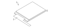
- FIG. 3 is a perspective view schematically showing the first liquid crystal display module.
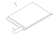
- FIG. 4 is a perspective view schematically showing the second liquid crystal display module.
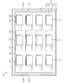
- FIG. 5 is a plan view schematically showing the transfer tray in a state in which the first liquid crystal display module is accommodated.
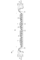
- FIG. 6 is a diagram schematically showing a cross section taken along line VI-VI in FIG.
- FIG. 7 is a cross-sectional view schematically showing a state in which the transfer trays of Embodiment 1 are stacked.
- FIG. 1 is a perspective view schematically illustrating a transfer tray according to the first embodiment.
- FIG. 2 is a diagram schematically showing a cross section taken along line II-II in FIG.
- FIG. 3 is a perspective view schematically showing the first liquid crystal display module.
- FIG. 8 is a plan view schematically showing the transfer tray in a state in which the second liquid crystal display module is accommodated.
- FIG. 9 is a plan view schematically showing the transfer tray of the second embodiment from the back side.
- FIG. 10 is a cross-sectional view schematically illustrating a state in which the transfer trays of Embodiment 2 are stacked.
- FIG. 1 is a perspective view schematically showing a transfer tray 10 of the present embodiment.
- FIG. 2 is a cross-sectional view schematically showing the transfer tray 10 along the line II-II in FIG.
- FIG. 3 is a perspective view schematically showing the first liquid crystal display module 1 housed in the transfer tray 10.
- FIG. 4 is a perspective view schematically showing the second liquid crystal display module 5 housed in the transfer tray 10.
- the transport tray 10 is a tray for storing and transporting plate-shaped products such as liquid crystal display panels and liquid crystal display modules.
- the first liquid crystal display module 1 and the second liquid crystal display module 5 will be described as examples of products stored in the transfer tray 10.
- the first liquid crystal display module 1 has a relatively flexible first liquid crystal display panel 2 in which a pair of substrates are bonded via a liquid crystal layer. 3) and the like are mounted.
- the second liquid crystal display module 5 is configured by mounting a second FPC 7 having a shape different from that of the first FPC 3 and the like on a second liquid crystal display panel 6 having a size larger than that of the first liquid crystal display panel 2. .
- the transport tray 10 is a so-called free tray that can store a plurality of products side by side. As shown in FIGS. 1 and 2, the transfer tray 10 includes a tray body 11 formed in a rectangular dish shape by molding with a mold.
- the tray body 11 is made of polypropylene resin or the like and is configured to be stacked in a plurality of stages. As shown in FIG. 2, the tray body 11 includes a bottom portion 12 having a flat bottom surface, and a side wall portion 13 provided so as to protrude upward on the peripheral edge of the bottom portion 12 over the entire circumference. A storage portion 14 for storing a plurality of products surrounded by the side wall portion 13 is provided.
- the side wall portion 13 includes an inner wall portion 15 provided to extend upward in a direction inclined outward with respect to the bottom portion 12, and a top portion provided to extend outward from the upper portion of the inner wall portion 15 in parallel to the bottom portion 12. 16, an outer wall portion 17 provided to extend downward from the outer end portion of the top portion 16 in a direction inclined outward with respect to the bottom portion 12, and projecting outward from the lower end portion of the outer wall portion 17. It is comprised by the collar part 18 which does.
- the positioning recessed part 19 divided by the inner wall part 15, the top part 16, and the outer wall part 17 is provided under the side wall part 13, and when stacking the conveyance trays 10 in a plurality of stages, the tray disposed in the lower stage By fitting the positioning concave portion 19 to the side wall portion 13 of the main body 11, the positional deviation between the transport trays 10 is suppressed.
- the side wall portion 13 is provided with a handle notch portion 20 on a pair of side portion portions 13a facing each other on both sides in the long side direction.
- Each notch portion 20 for a handle is partitioned by a flange 18 on the entire lower side.
- Each of these handle cutout portions 20 also has a function of preventing the tray body 11 from being distorted by an external impact. As a result, the load applied to each product due to the distortion of the tray body 11 is suppressed.
- a positioning sheet 23 on which a positioning mark indicating a position for placing each product is written.
- a predetermined number is written on each of the positioning sheets 23.
- an integral surface side mat 21 having cushioning properties for placing a plurality of products is provided so as to be disposed on substantially the entire surface of the bottom portion 12.
- a back surface side mat 22 having cushioning properties is attached to a position corresponding to the front surface side mat 21, that is, substantially the entire back surface of the bottom portion 12.
- the back surface side mat 22 is provided so as to abut on each product stored in the lower tray 10 when the transport trays 10 are stacked in a plurality of stages and to suppress the movement of each product.
- the mat having transparency includes, in addition to a colorless and transparent mat, a colored transparent mat and a slightly opaque semi-transparent mat.
- the transfer tray 10 stacks a plurality of products in a state in which the products are stored in the storage unit 14, whereby each product is sandwiched between the front surface side mat 21 and the back surface side mat 22 of the upper tray 10. It is configured to be retained.
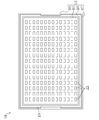
- FIG. 5 is a plan view schematically showing the transfer tray 10 in a state in which the first liquid crystal display module 1 is housed.
- FIG. 6 is a cross-sectional view schematically showing the transfer tray 10 along the line VI-VI in FIG.
- FIG. 7 is a cross-sectional view schematically showing the transport tray 10 in a stacked state.
- FIG. 8 is a plan view schematically showing the transfer tray 10 in a state where the second liquid crystal display module 5 is housed.
- the product is positioned in the storage unit 14 by the positioning marks 24 and 25 that are visible through the surface-side mat 21 and is arranged at a predetermined position.
- a predetermined number of products corresponding to the positioning marks are stored in the plurality of transfer trays 10.
- the peripheral portion of each first liquid crystal display module 1 is used as each first positioning mark 24.
- the first liquid crystal display modules 1 are placed on the front surface side mat 21 at intervals.
- the side wall portion 13 of the tray 10 in which the positioning recesses 19 of the tray 10 in which the plurality of transfer trays 10 in which the first liquid crystal display modules 1 are housed are arranged in the upper stage are arranged in the lower stage.
- the first liquid crystal display module 1 is ready to be transported by stacking so as to fit together and finally stacking empty trays 10.
- each first liquid crystal display module 1 housed in each transport tray 10 is held between the front surface side mat 21 and the back surface side mat 22 of the upper tray 10.
- each second liquid crystal display module is stored in the same manner as when the first liquid crystal display module 1 is stored.
- each second liquid crystal display module 5 stored in each transport tray 10 is connected to the front surface side mat 21 and the back surface side mat 22 of the upper tray 10. It will be in the state of being sandwiched and held.
- the first liquid crystal display module 1 and the second liquid crystal display module 5 are described as examples of products stored in the transport tray 10.
- the transport tray 10 includes the liquid crystal display modules 1 and 1.
- the liquid crystal display panels 2 and 6 constituting the liquid crystal display panels 5 and 6 and the substrates constituting the liquid crystal display panels 2 and 6 can be similarly housed and transported.
- Embodiment 1- when the transport trays 10 are stacked in a plurality of stages, the back surface side mat 22 provided on the upper tray body 11 comes into contact with the respective products stored therein. It is sandwiched and held between the side mat 21 and the back surface side mat 22 of the upper tray body 11. As a result, each product is fixed in the vertical direction and the movement in the direction parallel to the bottom surface of the storage unit 14 is suppressed. Therefore, it is necessary to form the transport tray 10 according to the size and shape of the product to be stored. There is no. For this reason, the products that can be stored are not limited by the size or shape, and each product can be stored appropriately even if the size or shape of each product to be stored changes.
- the movement of each product at the time of conveyance can be suppressed, and it can be shared for storing products having different sizes or shapes. And since the movement of each product at the time of conveyance can be suppressed, it can suppress that each product is damaged by the vibration and impact in conveyance work. Moreover, by being able to share the storage of each product having a different size or shape, the transport tray 10 for each product having a different size or shape can be formed with a common mold. Furthermore, since management for each type of transport tray 10 is not required, inventory management is facilitated, and there is no transport tray 10 that cannot be used even after the production of some products to be stored is completed. Cost can be reduced.
- the tray main body 11 is provided with positioning sheets 23 on which positioning marks 24 and 25 indicating positions for placing the respective products are provided between the tray body 11 and the surface side mat 21. Further, each product can be positioned and arranged at a predetermined position by the positioning marks 24 and 25, and the quantity management of the products stored in the transfer tray 10 can be facilitated. Further, even if a product of a new size or shape that cannot be positioned by each positioning mark 24, 25 is produced, a positioning mark suitable for the product is added to the positioning sheet 23, or A new size or shape product can be positioned and positioned at a predetermined position by replacing the positioning sheet with a positioning sheet displaying a positioning mark according to the product, etc., and stored in the transport tray 10 Can easily manage the quantity.
- FIG. 9 is a plan view schematically showing the transfer tray 10 of the present embodiment from the back side.
- FIG. 10 is a cross-sectional view schematically showing a state in which the transfer trays 10 of the present embodiment are stacked.
- the back surface side mat 22 is provided on substantially the entire back surface of the bottom portion 12 of the tray body 11, but the transport tray 10 of the present embodiment is configured as shown in FIG.
- a plurality of back surface side mats 22 are provided in a matrix on substantially the entire back surface of the bottom portion 12 of the tray body 11, and the configuration other than the back surface side mat 22 is the same as that of the first embodiment.
- the method of using the transport tray 10 is the same as in the first embodiment.
- the plurality of first liquid crystal display modules 1 are stored in the plurality of transfer trays 10 according to the first positioning marks 24, and FIG.
- a plurality of transfer trays 10 containing the first liquid crystal display modules 1 are stacked, and finally empty trays 10 are stacked.
- each first liquid crystal display module 1 housed in each transport tray 10 is held between the front surface side mat 21 and a part of the plurality of back surface side mats 22 of the upper tray 10. .
- each product has the front side mat 21 and the plurality of back side mats 22 of the upper tray 10.
- each product can be fixed in the vertical direction and the movement in the direction parallel to the bottom surface of the storage portion 14 can be suppressed, so that the movement of each product during transportation can be suppressed, Moreover, it can be shared for storing products of different sizes or shapes.
- the positioning marks 24 and 25 are displayed on the positioning sheet 23 disposed between the tray main body 11 and the surface side mat 21.
- the present invention is not limited to this, and each positioning mark 24 and 25 is displayed.
- the marks 24 and 25 may be displayed directly on the tray body 11. Even when the positioning marks 24 and 25 are displayed on the tray body 11 as described above, when storing the products, the products are positioned at predetermined positions by the positioning marks 24 and 25. And the quantity management of products stored in the transfer tray 10 can be facilitated.
- the first liquid crystal display module 1 and the second liquid crystal display module 5 will be described as examples of products stored in the transfer tray 10, and each liquid crystal display constituting the liquid crystal display modules 1 and 5 will be described.
- the panels 2 and 6 and the substrates constituting the liquid crystal display panels 2 and 6 can also be housed and transported, the present invention is not limited to this. It can also be used as a tray for storing and transporting display panels and display modules that make up other display devices such as electroluminescence display devices and plasma display devices. It can be applied as a tray.
- the present invention is useful for a transport tray, and in particular, transport that is desired to be able to be shared for storing products of different sizes and shapes while suppressing the movement of the product during transport. Suitable for trays.
Landscapes
- Packaging Frangible Articles (AREA)
Abstract
トレイ本体の表面には、複数の製品を載置するためのクッション性を有する表面側マットが設けられ、トレイ本体の裏面には、下段のトレイ本体に載置する複数の製品に当接して、各製品の移動を抑制するためのクッション性を有する裏面側マットが設けられている。
Description
本発明は、搬送用トレイに関するものである。
従来から、液晶表示装置等の表示装置の製造工場において、表示パネルや表示モジュール等の板状の製品を工程間で移動させるために用いられる搬送用トレイとして、製品を収納するための収納凹部を複数有し、これら各収納凹部に製品を1つずつ収納して、複数段に積み重ねて使用されるトレイが知られている(例えば、特許文献1参照)。このような搬送用トレイは、収納する製品のサイズ及び形状に合わせて各収納凹部が形成され、これら各収納凹部内で搬送時の製品の移動を制限して搬送作業における振動や衝撃によって製品が損傷することを抑制している。
しかし、上述の搬送用トレイにおいて、搬送時の製品の移動を制限するには収納する製品のサイズ及び形状に合わせて各収納凹部が形成されている必要があるため、液晶表示パネル等のように異なるサイズの規格を有するものや液晶表示モジュール等のように実装された配線基板の実装位置及び形状によって製品全体の形状が変わるものについては、各製品のサイズ又は形状毎に各収納凹部の形状や大きさを変えて複数種類の搬送用トレイを用意する必要がある。これら各種類の搬送用トレイの成形には、専用の金型がそれぞれ必要であるため、多額の費用がかかる。さらに、このように複数種類の搬送用トレイを用意する場合には、搬送用トレイの種類毎の管理が必要なために在庫管理が煩雑になり、且つ収納対象の製品の生産が終了した搬送用トレイは使用不可能となって在庫が残ってしまう。
本発明は、斯かる点に鑑みてなされたものであり、その目的とするところは、搬送時の各製品の移動を抑制し、且つサイズ又は形状の異なる製品の収納に共用可能にすることにある。
上記の目的を達成するために、この発明では、トレイ本体の表面に複数の製品を載置するためのクッション性を有する表面側マットを設け、トレイ本体の裏面に、下段のトレイ本体に載置する複数の製品に当接して、それら各製品の移動を抑制するためのクッション性を有する裏面側マットを設けるようにした。
具体的に、本発明に係る搬送用トレイは、複数の板状の製品を並べて収納するためのトレイ本体を有し、該トレイ本体が複数段に積み重なるように構成された搬送用トレイであって、上記トレイ本体の表面には、上記複数の製品を載置するためのクッション性を有する表面側マットが設けられ、上記トレイ本体の裏面には、下段のトレイ本体に載置する複数の製品に当接して、該各製品の移動を抑制するためのクッション性を有する裏面側マットが設けられていることを特徴とする。
この構成によると、トレイを複数段に積み重ねたときに、上段のトレイ本体に設けられた裏面側マットが収納した各製品に当接するため、それら各製品が表面側マットと上段のトレイ本体の裏面側マットとに挟まれて保持される。そのことにより、各製品は上下方向に固定されると共にトレイ本体の底面に平行な方向への移動が抑制されるので、収納する製品のサイズや形状に合わせて搬送用トレイを成形する必要がない。このため、収納可能な製品がそのサイズや形状によって制限されず、収納する各製品のサイズ又は形状が変わったとしても、各製品を適宜収納することが可能になる。したがって、搬送時の各製品の移動が抑制され、且つサイズ又は形状の異なる製品の収納に共用することが可能になる。そして、搬送時の各製品の移動が抑制されることにより、搬送作業における振動や衝撃によって各製品が損傷することが抑制される。また、サイズ又は形状の異なる各製品の収納に共用可能になることにより、それらサイズ又は形状が異なる各製品の搬送用トレイを共通の金型で成形することが可能になる。さらに、搬送用トレイの種類毎の管理が不要となるので在庫管理が容易になり、収納対象の一部の製品の生産が終了しても使用不可能になる搬送用トレイが発生しないので、コストが低減する。
上記トレイ本体には、上記各製品を載置する位置を示す位置決めマークがそれぞれ設けられていることが好ましい。
この構成によると、各製品を収納する際に、各位置決めマークによって各製品を所定の位置に位置決めして配置させることが可能になり、且つ搬送用トレイに収納する製品の数量管理を容易にすることが可能になる。
上記トレイ本体には、上記表面側マットとの間に上記各位置決めマークが表示された位置決めシートが設けられていることが好ましい。
この構成によると、各位置決めマークによって位置決めすることが不可能な新しいサイズ又は形状の製品が生産されることになったとしても、その製品に合わせた位置決めマークを位置決めシートに追加する、又はその製品に合わせた位置決めマークが表示された位置決めシートに位置決めシートを交換する等して、新しいサイズ又は形状の製品についても、所定の位置に位置決めして配置させることが可能になり、且つ搬送用トレイに収納する製品の数量管理を容易にすることが可能になる。
上記各製品は、液晶表示モジュールであってもよい。
この構成によると、搬送時の各液晶表示モジュールの移動が抑制され、且つサイズ又は形状の異なる液晶表示モジュールの収納に共用することが可能になる。
本発明によれば、トレイ本体の表面に、複数の製品を載置するためのクッション性を有する表面側マットが設けられ、トレイ本体の裏面に、下段のトレイ本体に載置する複数の製品に当接して、それら各製品の移動を抑制するためのクッション性を有する裏面側マットが設けられているので、搬送時の製品の移動を抑制でき、且つサイズや形状の異なる製品の収納に共用することができる。
以下、本発明の実施形態を図面に基づいて詳細に説明する。尚、本発明は、以下の各実施形態に限定されるものではない。
《発明の実施形態1》
図1~図8は、本発明の実施形態1を示している。図1は、本実施形態の搬送用トレイ10を概略的に示す斜視図である。図2は、図1のII-II線に沿って搬送用トレイ10を概略的に示す断面図である。図3は、搬送用トレイ10に収納する第1液晶表示モジュール1を概略的に示す斜視図である。図4は、搬送用トレイ10に収納する第2液晶表示モジュール5を概略的に示す斜視図である。
図1~図8は、本発明の実施形態1を示している。図1は、本実施形態の搬送用トレイ10を概略的に示す斜視図である。図2は、図1のII-II線に沿って搬送用トレイ10を概略的に示す断面図である。図3は、搬送用トレイ10に収納する第1液晶表示モジュール1を概略的に示す斜視図である。図4は、搬送用トレイ10に収納する第2液晶表示モジュール5を概略的に示す斜視図である。
搬送用トレイ10は、液晶表示パネル及び液晶表示モジュール等の板状の製品を収納して搬送するためのトレイである。本実施形態では、この搬送用トレイ10に収納する製品として、第1液晶表示モジュール1及び第2液晶表示モジュール5を例に挙げて説明する。第1液晶表示モジュール1は、図3に示すように、一対の基板が液晶層を介して貼り合わされた比較的小型の第1液晶表示パネル2に第1フレキシブルプリント配線基板(Flexible Printed Circuit:以下、FPCと称する)3等が実装されて構成されている。第2液晶表示モジュール5は、図4に示すように、第1液晶表示パネル2よりもサイズの大きな第2液晶表示パネル6に第1FPC3と形状の異なる第2FPC7等が実装されて構成されている。
搬送用トレイ10は、複数の製品を並べて収納することが可能ないわゆるフリートレイである。この搬送用トレイ10は、図1及び図2に示すように、金型による成形によって矩形皿状に形成されたトレイ本体11を備えている。
トレイ本体11は、ポリプロピレン樹脂等によって形成され、複数段に積み重なるように構成されている。このトレイ本体11は、図2に示すように、平坦な底面を有する底部12と、底部12の周縁部に全周に亘って上側に突出するように設けられた側壁部13とで構成され、側壁部13に囲まれた複数の製品を収納するための収納部14を有している。
側壁部13は、底部12に対して外側に傾斜する方向へ上側に延びるように設けられた内壁部15と、この内壁部15の上部から底部12に平行に外側に延びるように設けられた頂部16と、この頂部16における外側の端部から底部12に対して外側に傾斜する方向へ下側に延びるように設けられた外壁部17と、この外壁部17の下側端部から外側に突出する鍔部18とにより構成されている。そして、側壁部13の下側には内壁部15、頂部16及び外壁部17によって区画された位置決め用凹部19が設けられており、搬送用トレイ10を複数段に積み重ねるときには、下段に配置するトレイ本体11の側壁部13にこの位置決め用凹部19を嵌合させることにより、搬送用トレイ10同士の位置ずれが抑制されるようになっている。
この側壁部13には、図1に示すように、長辺方向の両側で互いに対向する一対の側辺部分13aに、把手用切欠き部20がそれぞれ設けられている。そして、各把手用切欠き部20は、下側全体が鍔部18によって区画されている。そのことにより、搬送用トレイ10の積み重ね作業及び離脱作業を容易にすることが可能になっている。これら各把手用切欠き部20は、外部からの衝撃によってトレイ本体11が歪むことを抑制する機能も有している。これにより、トレイ本体11が歪むことによって各製品に荷重が加わることが抑制されるようになっている。
底部12の表面には、各製品を載置する位置を示す位置決めマークが表記された位置決めシート23が設けられている。本実施形態では、位置決めマークとして、各第1液晶表示モジュール1を配置する位置を示す第1位置決めマーク24及び各第2液晶表示モジュール5を配置する位置を示す第2位置決めマーク25がマトリクス状に位置決めシート23にそれぞれ所定の個数表記されている。
そして、位置決めシート23上には、図2に示すように、底部12の略全面に配置するように複数の製品を載置するためのクッション性を有する一体の表面側マット21が設けられている。また、底部12の裏面には、表面側マット21に対応する位置、つまり底部12の裏面の略全面にクッション性を有する裏面側マット22が貼り付けられている。この裏面側マット22は、搬送用トレイ10を複数段に積み重ねたときに、下段のトレイ10に収納された各製品に当接して、それら各製品の移動を抑制するように設けられている。
これら表面側マット21及び裏面側マット22としては、透明性を有すると共に帯電防止処理が施された発泡ポリエチレン樹脂等からなるマット、例えばJSP社製の商品名「ミラマットA」等を用いることが可能である。ここで、透明性を有するマットには、無色透明なマットの他に、色付き透明のマット及び若干白濁した半透明のマットも含まれる。
このように、搬送用トレイ10は、複数の製品を収納部14の内部に収納した状態で積み重ねることにより、表面側マット21と上段のトレイ10の裏面側マット22とによって各製品が挟まれて保持されるように構成されている。
-使用方法-
次に、上記搬送用トレイ10の使用方法について、図5~図8を参照しながら説明する。図5は、第1液晶表示モジュール1を収納した状態の搬送用トレイ10を概略的に示す平面図である。図6は、図5のVI-VI線に沿って搬送用トレイ10を概略的に示す断面図である。図7は、積み重ねた状態の搬送用トレイ10を概略的に示す断面図である。図8は、第2液晶表示モジュール5を収納した状態の搬送用トレイ10を概略的に示す平面図である。
次に、上記搬送用トレイ10の使用方法について、図5~図8を参照しながら説明する。図5は、第1液晶表示モジュール1を収納した状態の搬送用トレイ10を概略的に示す平面図である。図6は、図5のVI-VI線に沿って搬送用トレイ10を概略的に示す断面図である。図7は、積み重ねた状態の搬送用トレイ10を概略的に示す断面図である。図8は、第2液晶表示モジュール5を収納した状態の搬送用トレイ10を概略的に示す平面図である。
搬送用トレイ10を用いて製品を搬送するには、まず、表面側マット21を透過して視認される各位置決めマーク24,25によって収納部14に製品を位置決めして所定の位置に配置させることにより、複数の搬送用トレイ10に位置決めマークに応じた所定の個数の製品を収納する。例えば、複数の第1液晶表示モジュール1を搬送用トレイ10に収納する場合には、図5及び図6に示すように、各第1液晶表示モジュール1の周縁部を各第1位置決めマーク24に合わせて互いに間隔をおいて各第1液晶表示モジュール1を表面側マット21に載置する。
次に、図7に示すように、各第1液晶表示モジュール1を収納した複数の搬送用トレイ10を、上段に配置させるトレイ10の位置決め用凹部19を下段に配置させるトレイ10の側壁部13に嵌合させるように積み重ねて、最後に空のトレイ10を積み重ねることにより、第1液晶表示モジュール1の搬送準備が完了する。このとき、各搬送用トレイ10に収納された各第1液晶表示モジュール1は表面側マット21と上段のトレイ10の裏面側マット22とに挟まれて保持された状態となる。
また、複数の第2液晶表示モジュール5を搬送用トレイ10に収納する場合には、図8に示すように、各第2液晶表示モジュール5の周縁部を各第2位置決めマーク25に合わせて互いに間隔をおいて各第2液晶表示モジュール5を表面側マット21に載置する。そして、複数の搬送用トレイ10に対して収納部14内に複数の第2液晶表示モジュール5を載置した後、第1液晶表示モジュール1を収納した場合と同様に、各第2液晶表示モジュール5を収納した複数の搬送用トレイ10を積み重ねて、最後に空のトレイ10を積み重ねることにより、第2液晶表示モジュール5の搬送準備が完了する。このとき、第1液晶表示モジュール1を収納した場合と同様に、各搬送用トレイ10に収納された各第2液晶表示モジュール5は表面側マット21と上段のトレイ10の裏面側マット22とに挟まれて保持された状態となる。
このように積み重ねた複数の搬送用トレイ10を搬送した後、これら複数の搬送用トレイ10から各製品を取り出すには、下段のトレイ10の一対の把手用切欠き部20に手を入れて上段のトレイ10の鍔部18を把持し、例えば複数の搬送用トレイ10を最上段から順に下段のトレイ10と離脱させる。そして、各搬送用トレイ10から各製品を取り出す。
尚、本実施形態では、搬送用トレイ10に収納する製品として第1液晶表示モジュール1及び第2液晶表示モジュール5を例に挙げて説明したが、搬送用トレイ10は、これら液晶表示モジュール1,5を構成する液晶表示パネル2,6、さらにそれら液晶表示パネル2,6を構成する各基板等についても同様に収納して搬送することが可能である。
-実施形態1の効果-
したがって、この実施形態1によると、搬送用トレイ10を複数段に積み重ねたときに、上段のトレイ本体11に設けられた裏面側マット22が収納した各製品に当接するため、それら各製品が表面側マット21と上段のトレイ本体11の裏面側マット22とに挟まれて保持される。そのことにより、各製品は上下方向に固定されると共に収納部14の底面に平行な方向への移動が抑制されるので、収納する製品のサイズや形状に合わせて搬送用トレイ10を成形する必要がない。このため、収納可能な製品がそのサイズや形状によって制限されず、収納する各製品のサイズ又は形状が変わったとしても、各製品を適宜収納することができる。したがって、搬送時の各製品の移動を抑制でき、且つサイズ又は形状の異なる製品の収納に共用することができる。そして、搬送時の各製品の移動を抑制できることにより搬送作業における振動や衝撃によって各製品が損傷することを抑制できる。また、サイズ又は形状の異なる各製品の収納に共用できることにより、それらサイズ又は形状が異なる各製品の搬送用トレイ10を共通の金型で成形できる。さらに、搬送用トレイ10の種類毎の管理が不要となるので在庫管理が容易になり、収納対象の一部の製品の生産が終了しても使用不可能になる搬送用トレイ10が発生しないので、コストを低減できる。
したがって、この実施形態1によると、搬送用トレイ10を複数段に積み重ねたときに、上段のトレイ本体11に設けられた裏面側マット22が収納した各製品に当接するため、それら各製品が表面側マット21と上段のトレイ本体11の裏面側マット22とに挟まれて保持される。そのことにより、各製品は上下方向に固定されると共に収納部14の底面に平行な方向への移動が抑制されるので、収納する製品のサイズや形状に合わせて搬送用トレイ10を成形する必要がない。このため、収納可能な製品がそのサイズや形状によって制限されず、収納する各製品のサイズ又は形状が変わったとしても、各製品を適宜収納することができる。したがって、搬送時の各製品の移動を抑制でき、且つサイズ又は形状の異なる製品の収納に共用することができる。そして、搬送時の各製品の移動を抑制できることにより搬送作業における振動や衝撃によって各製品が損傷することを抑制できる。また、サイズ又は形状の異なる各製品の収納に共用できることにより、それらサイズ又は形状が異なる各製品の搬送用トレイ10を共通の金型で成形できる。さらに、搬送用トレイ10の種類毎の管理が不要となるので在庫管理が容易になり、収納対象の一部の製品の生産が終了しても使用不可能になる搬送用トレイ10が発生しないので、コストを低減できる。
上記トレイ本体11には、表面側マット21との間に各製品を載置する位置を示す位置決めマーク24,25がそれぞれ表示された位置決めシート23が設けられているため、各製品を収納する際に、各位置決めマーク24,25によって各製品を所定の位置に位置決めして配置でき、且つ搬送用トレイ10に収納する製品の数量管理を容易にできる。さらに、各位置決めマーク24,25によって位置決めすることが不可能な新しいサイズ又は形状の製品が生産されることになったとしても、その製品に合わせた位置決めマークを位置決めシート23に追加する、又はその製品に合わせた位置決めマークが表示された位置決めシートに位置決めシートを交換する等して、新しいサイズ又は形状の製品についても、所定の位置に位置決めして配置でき、且つ搬送用トレイ10に収納する製品の数量管理を容易にできる。
《発明の実施形態2》
図9及び図10は、本発明の実施形態2を示している。尚、以降の各実施形態では、図1~図8と同じ部分については同じ符号を付して、その詳細な説明を省略する。図9は、本実施形態の搬送用トレイ10を裏面側から概略的に示す平面図である。図10は、本実施形態の搬送用トレイ10を積み重ねた状態を概略的に示す断面図である。
図9及び図10は、本発明の実施形態2を示している。尚、以降の各実施形態では、図1~図8と同じ部分については同じ符号を付して、その詳細な説明を省略する。図9は、本実施形態の搬送用トレイ10を裏面側から概略的に示す平面図である。図10は、本実施形態の搬送用トレイ10を積み重ねた状態を概略的に示す断面図である。
上記実施形態1では、トレイ本体11における底部12の裏面の略全体に一体の裏面側マット22が設けられているとしたが、本実施形態の搬送用トレイ10は、図9に示すように、裏面側マット22がトレイ本体11における底部12の裏面の略全体にマトリクス状に複数設けられており、この裏面側マット22以外の構成については上記実施形態1と同様である。
また、この搬送用トレイ10の使用方法についても上記第1実施形態と同様である。例えば、搬送用トレイ10に第1液晶表示モジュール1を収納する場合には、複数の搬送用トレイ10に各第1位置決めマーク24に合わせて複数の第1液晶表示モジュール1を収納し、図10に示すようにそれら第1液晶表示モジュール1を収納した複数の搬送用トレイ10を積み重ねて、最後に空のトレイ10を積み重ねる。このとき、各搬送用トレイ10に収納された各第1液晶表示モジュール1は表面側マット21と上段のトレイ10の複数の裏面側マット22の一部とに挟まれて保持された状態となる。
-実施形態2の効果-
したがって、この実施形態2によっても、上記実施形態1と同様に、搬送用トレイ10を複数段に積み重ねたときに、各製品が表面側マット21と上段のトレイ10の複数の裏面側マット22の一部とに挟まれて保持されることにより、各製品を上下方向に固定できると共に収納部14の底面に平行な方向への移動を抑制できるので、搬送時の各製品の移動を抑制でき、且つサイズ又は形状の異なる製品の収納に共用することができる。
したがって、この実施形態2によっても、上記実施形態1と同様に、搬送用トレイ10を複数段に積み重ねたときに、各製品が表面側マット21と上段のトレイ10の複数の裏面側マット22の一部とに挟まれて保持されることにより、各製品を上下方向に固定できると共に収納部14の底面に平行な方向への移動を抑制できるので、搬送時の各製品の移動を抑制でき、且つサイズ又は形状の異なる製品の収納に共用することができる。
《その他の実施形態》
上記実施形態1では、各位置決めマーク24,25がトレイ本体11と表面側マット21との間に配置された位置決めシート23に表示されているとしたが、本発明はこれに限られず、各位置決めマーク24,25は、トレイ本体11に直接に表示されていてもよい。このようにトレイ本体11に各位置決めマーク24,25が表示されている場合にも、各製品を収納する際に、各位置決めマーク24,25によって各製品を所定の位置に位置決めして配置することが可能になり、且つ搬送用トレイ10に収納する製品の数量管理を容易にすることが可能になる。
上記実施形態1では、各位置決めマーク24,25がトレイ本体11と表面側マット21との間に配置された位置決めシート23に表示されているとしたが、本発明はこれに限られず、各位置決めマーク24,25は、トレイ本体11に直接に表示されていてもよい。このようにトレイ本体11に各位置決めマーク24,25が表示されている場合にも、各製品を収納する際に、各位置決めマーク24,25によって各製品を所定の位置に位置決めして配置することが可能になり、且つ搬送用トレイ10に収納する製品の数量管理を容易にすることが可能になる。
上記実施形態1では、搬送用トレイ10に収納する製品として、第1液晶表示モジュール1及び第2液晶表示モジュール5を例に挙げて説明し、これら液晶表示モジュール1,5を構成する各液晶表示パネル2,6、さらにそれら各液晶表示パネル2,6を構成する各基板についても収納して搬送することが可能であるとしたが、本発明はこれに限られず、搬送用トレイ10は、有機エレクトロルミネッセンス表示装置やプラズマ表示装置等の他の表示装置を構成する表示パネルや表示モジュール等を収納して搬送するためのトレイとしても適用可能であり、その他にも板状の製品であれば搬送用のトレイとして適用可能である。
以上説明したように、本発明は、搬送用トレイについて有用であり、特に、搬送時の製品の移動を抑制し、且つサイズや形状の異なる製品の収納に共用可能にすることが要望される搬送用トレイに適している。
1 第1液晶表示モジュール
5 第2液晶表示モジュール
10 搬送用トレイ
14 収納部
21 表面側マット
22 裏面側マット
23 位置決めシート
24 第1位置決めマーク
25 第2位置決めマーク
5 第2液晶表示モジュール
10 搬送用トレイ
14 収納部
21 表面側マット
22 裏面側マット
23 位置決めシート
24 第1位置決めマーク
25 第2位置決めマーク
Claims (4)
- 複数の板状の製品を並べて収納するためのトレイ本体を有し、該トレイ本体が複数段に積み重なるように構成された搬送用トレイであって、
上記トレイ本体の表面には、上記複数の製品を載置するためのクッション性を有する表面側マットが設けられ、
上記トレイ本体の裏面には、下段のトレイ本体に載置する複数の製品に当接して、該各製品の移動を抑制するためのクッション性を有する裏面側マットが設けられている
ことを特徴とする搬送用トレイ。 - 請求項1に記載の搬送用トレイにおいて、
上記トレイ本体には、上記各製品を載置する位置を示す位置決めマークがそれぞれ設けられている
ことを特徴とする搬送用トレイ。 - 請求項2に記載の搬送用トレイにおいて、
上記トレイ本体には、上記表面側マットとの間に上記各位置決めマークが表示された位置決めシートが設けられている
ことを特徴とする搬送用トレイ。 - 請求項1に記載の搬送用トレイにおいて、
上記各製品は、液晶表示モジュールである
ことを特徴とする搬送用トレイ。
Priority Applications (1)
| Application Number | Priority Date | Filing Date | Title |
|---|---|---|---|
| US13/130,599 US20110226711A1 (en) | 2008-12-04 | 2009-07-27 | Transportation tray |
Applications Claiming Priority (2)
| Application Number | Priority Date | Filing Date | Title |
|---|---|---|---|
| JP2008310288 | 2008-12-04 | ||
| JP2008-310288 | 2008-12-04 |
Publications (1)
| Publication Number | Publication Date |
|---|---|
| WO2010064342A1 true WO2010064342A1 (ja) | 2010-06-10 |
Family
ID=42233002
Family Applications (1)
| Application Number | Title | Priority Date | Filing Date |
|---|---|---|---|
| PCT/JP2009/003525 Ceased WO2010064342A1 (ja) | 2008-12-04 | 2009-07-27 | 搬送用トレイ |
Country Status (2)
| Country | Link |
|---|---|
| US (1) | US20110226711A1 (ja) |
| WO (1) | WO2010064342A1 (ja) |
Cited By (5)
| Publication number | Priority date | Publication date | Assignee | Title |
|---|---|---|---|---|
| CN102931123A (zh) * | 2011-08-12 | 2013-02-13 | 英飞凌科技股份有限公司 | 在干燥和压力支撑组装过程中固定半导体管芯 |
| CN103010557A (zh) * | 2012-12-18 | 2013-04-03 | 杭州中亚机械股份有限公司 | 一种装箱托架及其摆放方法 |
| JP2014038947A (ja) * | 2012-08-17 | 2014-02-27 | Disco Abrasive Syst Ltd | 搬送トレイ |
| JP2014044279A (ja) * | 2012-08-27 | 2014-03-13 | Japan Display Inc | 表示パネル |
| CN103808983A (zh) * | 2012-11-08 | 2014-05-21 | 三星显示有限公司 | 用于检查面板的引导组件和具有引导组件的托盘 |
Families Citing this family (6)
| Publication number | Priority date | Publication date | Assignee | Title |
|---|---|---|---|---|
| JP2014518694A (ja) * | 2011-05-03 | 2014-08-07 | ロデリック・ウィリアム・フィリップス | 家具装置およびキット、システムならびにそれらの使用法 |
| CN102897436A (zh) * | 2012-11-13 | 2013-01-30 | 深圳市华星光电技术有限公司 | 一种液晶显示面板组件的包装盒 |
| US9533824B2 (en) | 2012-11-13 | 2017-01-03 | Shenzhen China Star Optoelectronics Technology Co., Ltd | Packaging box for LCD panel components |
| KR102069329B1 (ko) * | 2013-09-12 | 2020-01-23 | 삼성디스플레이 주식회사 | 디스플레이 장치 |
| JP6978710B1 (ja) * | 2020-07-06 | 2021-12-08 | 日亜化学工業株式会社 | トレイ及び梱包体 |
| CN115298100B (zh) * | 2021-03-03 | 2024-12-13 | 瑞仪(广州)光电子器件有限公司 | 承载盘及承载盘堆叠组件 |
Citations (6)
| Publication number | Priority date | Publication date | Assignee | Title |
|---|---|---|---|---|
| JPH05170275A (ja) * | 1991-12-16 | 1993-07-09 | Hitachi Ltd | 半導体装置用収納トレイ |
| JPH09328180A (ja) * | 1996-06-06 | 1997-12-22 | Nippon Dempa Kogyo Co Ltd | 光学素子収納具 |
| JPH11198938A (ja) * | 1997-11-14 | 1999-07-27 | Sharp Corp | 包装トレイ |
| JP2002337951A (ja) * | 2001-05-21 | 2002-11-27 | Hitachi Transport Syst Ltd | 板状易損品の搬送用トレイおよびそれを用いた梱包方法 |
| JP2005320033A (ja) * | 2004-05-10 | 2005-11-17 | Daiwa Shinku:Kk | リードピン付き液晶パネルの搬送容器 |
| JP2008091696A (ja) * | 2006-10-03 | 2008-04-17 | Seiko Instruments Inc | 半導体チップトレイ |
Family Cites Families (2)
| Publication number | Priority date | Publication date | Assignee | Title |
|---|---|---|---|---|
| DE3611704A1 (de) * | 1986-04-08 | 1987-10-22 | Basf Ag | Verfahren zur herstellung von schlagfestem poly(alkyl)styrol |
| JPS6346246A (ja) * | 1986-04-14 | 1988-02-27 | Sumitomo Chem Co Ltd | エチレン・α−オレフイン共重合系加硫ゴム組成物 |
-
2009
- 2009-07-27 US US13/130,599 patent/US20110226711A1/en not_active Abandoned
- 2009-07-27 WO PCT/JP2009/003525 patent/WO2010064342A1/ja not_active Ceased
Patent Citations (6)
| Publication number | Priority date | Publication date | Assignee | Title |
|---|---|---|---|---|
| JPH05170275A (ja) * | 1991-12-16 | 1993-07-09 | Hitachi Ltd | 半導体装置用収納トレイ |
| JPH09328180A (ja) * | 1996-06-06 | 1997-12-22 | Nippon Dempa Kogyo Co Ltd | 光学素子収納具 |
| JPH11198938A (ja) * | 1997-11-14 | 1999-07-27 | Sharp Corp | 包装トレイ |
| JP2002337951A (ja) * | 2001-05-21 | 2002-11-27 | Hitachi Transport Syst Ltd | 板状易損品の搬送用トレイおよびそれを用いた梱包方法 |
| JP2005320033A (ja) * | 2004-05-10 | 2005-11-17 | Daiwa Shinku:Kk | リードピン付き液晶パネルの搬送容器 |
| JP2008091696A (ja) * | 2006-10-03 | 2008-04-17 | Seiko Instruments Inc | 半導体チップトレイ |
Cited By (6)
| Publication number | Priority date | Publication date | Assignee | Title |
|---|---|---|---|---|
| CN102931123A (zh) * | 2011-08-12 | 2013-02-13 | 英飞凌科技股份有限公司 | 在干燥和压力支撑组装过程中固定半导体管芯 |
| US8999758B2 (en) | 2011-08-12 | 2015-04-07 | Infineon Technologies Ag | Fixing semiconductor die in dry and pressure supported assembly processes |
| JP2014038947A (ja) * | 2012-08-17 | 2014-02-27 | Disco Abrasive Syst Ltd | 搬送トレイ |
| JP2014044279A (ja) * | 2012-08-27 | 2014-03-13 | Japan Display Inc | 表示パネル |
| CN103808983A (zh) * | 2012-11-08 | 2014-05-21 | 三星显示有限公司 | 用于检查面板的引导组件和具有引导组件的托盘 |
| CN103010557A (zh) * | 2012-12-18 | 2013-04-03 | 杭州中亚机械股份有限公司 | 一种装箱托架及其摆放方法 |
Also Published As
| Publication number | Publication date |
|---|---|
| US20110226711A1 (en) | 2011-09-22 |
Similar Documents
| Publication | Publication Date | Title |
|---|---|---|
| WO2010064342A1 (ja) | 搬送用トレイ | |
| KR100615026B1 (ko) | 디스플레이용 기판 수납용 트레이, 및 그 디스플레이용기판을 제거하는 장치 및 방법 | |
| JP5983988B2 (ja) | 輸送用トレイ、それを用いた輸送資材及び輸送方法 | |
| CN201367197Y (zh) | 包装箱 | |
| JP2011073688A (ja) | ガラス基板収納用トレイ | |
| JP5186340B2 (ja) | 板材搬送用トレイの緩衝部材、およびその緩衝部材が取付けられた板材搬送用トレイ | |
| TW202106582A (zh) | 玻璃板包裝體 | |
| JP4106225B2 (ja) | 電子部品等の収納トレー | |
| WO2014194545A1 (zh) | 一种液晶模组前框包装装置 | |
| TW202009182A (zh) | 緩衝包裝裝置 | |
| US20250153919A1 (en) | Display device packaging assembly | |
| CN101717014B (zh) | 包装箱结构 | |
| JP4862614B2 (ja) | ガラス板梱包方法 | |
| JP5375442B2 (ja) | 基板搬送用パレット | |
| CN208616394U (zh) | 一种托盘 | |
| JP5357261B2 (ja) | 収納トレイ | |
| CN217836505U (zh) | 印刷板组装体及其与显示面板的移送用托架 | |
| JP6922894B2 (ja) | 梱包体および梱包体の製造方法 | |
| JP2007073871A (ja) | 薄形表示装置用基板の工程間搬送に使用するトレイ及びそれを使用した薄形表示装置用基板の出荷方法 | |
| JP4947543B2 (ja) | 緩衝包装体及び梱包方 | |
| JP2008100693A (ja) | 収納トレイ | |
| CN103879632B (zh) | 折叠托盘 | |
| TWI412475B (zh) | 偏光板用裝載箱 | |
| CN207293106U (zh) | 玻璃板包装体 | |
| JP3242645U (ja) | トレイ |
Legal Events
| Date | Code | Title | Description |
|---|---|---|---|
| 121 | Ep: the epo has been informed by wipo that ep was designated in this application |
Ref document number: 09830113 Country of ref document: EP Kind code of ref document: A1 |
|
| WWE | Wipo information: entry into national phase |
Ref document number: 13130599 Country of ref document: US |
|
| NENP | Non-entry into the national phase |
Ref country code: DE |
|
| 122 | Ep: pct application non-entry in european phase |
Ref document number: 09830113 Country of ref document: EP Kind code of ref document: A1 |
|
| NENP | Non-entry into the national phase |
Ref country code: JP |