WO2010061572A1 - 燃料電池用圧力調整バルブおよび燃料電池 - Google Patents
燃料電池用圧力調整バルブおよび燃料電池 Download PDFInfo
- Publication number
- WO2010061572A1 WO2010061572A1 PCT/JP2009/006309 JP2009006309W WO2010061572A1 WO 2010061572 A1 WO2010061572 A1 WO 2010061572A1 JP 2009006309 W JP2009006309 W JP 2009006309W WO 2010061572 A1 WO2010061572 A1 WO 2010061572A1
- Authority
- WO
- WIPO (PCT)
- Prior art keywords
- fuel
- valve
- fuel cell
- pressure regulating
- pressure
- Prior art date
- Legal status (The legal status is an assumption and is not a legal conclusion. Google has not performed a legal analysis and makes no representation as to the accuracy of the status listed.)
- Ceased
Links
Images










Classifications
-
- F—MECHANICAL ENGINEERING; LIGHTING; HEATING; WEAPONS; BLASTING
- F16—ENGINEERING ELEMENTS AND UNITS; GENERAL MEASURES FOR PRODUCING AND MAINTAINING EFFECTIVE FUNCTIONING OF MACHINES OR INSTALLATIONS; THERMAL INSULATION IN GENERAL
- F16K—VALVES; TAPS; COCKS; ACTUATING-FLOATS; DEVICES FOR VENTING OR AERATING
- F16K17/00—Safety valves; Equalising valves, e.g. pressure relief valves
- F16K17/02—Safety valves; Equalising valves, e.g. pressure relief valves opening on surplus pressure on one side; closing on insufficient pressure on one side
-
- F—MECHANICAL ENGINEERING; LIGHTING; HEATING; WEAPONS; BLASTING
- F16—ENGINEERING ELEMENTS AND UNITS; GENERAL MEASURES FOR PRODUCING AND MAINTAINING EFFECTIVE FUNCTIONING OF MACHINES OR INSTALLATIONS; THERMAL INSULATION IN GENERAL
- F16K—VALVES; TAPS; COCKS; ACTUATING-FLOATS; DEVICES FOR VENTING OR AERATING
- F16K17/00—Safety valves; Equalising valves, e.g. pressure relief valves
- F16K17/02—Safety valves; Equalising valves, e.g. pressure relief valves opening on surplus pressure on one side; closing on insufficient pressure on one side
- F16K17/04—Safety valves; Equalising valves, e.g. pressure relief valves opening on surplus pressure on one side; closing on insufficient pressure on one side spring-loaded
-
- H—ELECTRICITY
- H01—ELECTRIC ELEMENTS
- H01M—PROCESSES OR MEANS, e.g. BATTERIES, FOR THE DIRECT CONVERSION OF CHEMICAL ENERGY INTO ELECTRICAL ENERGY
- H01M8/00—Fuel cells; Manufacture thereof
- H01M8/04—Auxiliary arrangements, e.g. for control of pressure or for circulation of fluids
- H01M8/04082—Arrangements for control of reactant parameters, e.g. pressure or concentration
- H01M8/04186—Arrangements for control of reactant parameters, e.g. pressure or concentration of liquid-charged or electrolyte-charged reactants
-
- H—ELECTRICITY
- H01—ELECTRIC ELEMENTS
- H01M—PROCESSES OR MEANS, e.g. BATTERIES, FOR THE DIRECT CONVERSION OF CHEMICAL ENERGY INTO ELECTRICAL ENERGY
- H01M8/00—Fuel cells; Manufacture thereof
- H01M8/04—Auxiliary arrangements, e.g. for control of pressure or for circulation of fluids
- H01M8/04082—Arrangements for control of reactant parameters, e.g. pressure or concentration
- H01M8/04201—Reactant storage and supply, e.g. means for feeding, pipes
-
- H—ELECTRICITY
- H01—ELECTRIC ELEMENTS
- H01M—PROCESSES OR MEANS, e.g. BATTERIES, FOR THE DIRECT CONVERSION OF CHEMICAL ENERGY INTO ELECTRICAL ENERGY
- H01M8/00—Fuel cells; Manufacture thereof
- H01M8/04—Auxiliary arrangements, e.g. for control of pressure or for circulation of fluids
- H01M8/04082—Arrangements for control of reactant parameters, e.g. pressure or concentration
- H01M8/04201—Reactant storage and supply, e.g. means for feeding, pipes
- H01M8/04208—Cartridges, cryogenic media or cryogenic reservoirs
-
- H—ELECTRICITY
- H01—ELECTRIC ELEMENTS
- H01M—PROCESSES OR MEANS, e.g. BATTERIES, FOR THE DIRECT CONVERSION OF CHEMICAL ENERGY INTO ELECTRICAL ENERGY
- H01M8/00—Fuel cells; Manufacture thereof
- H01M8/10—Fuel cells with solid electrolytes
- H01M8/1009—Fuel cells with solid electrolytes with one of the reactants being liquid, solid or liquid-charged
-
- Y—GENERAL TAGGING OF NEW TECHNOLOGICAL DEVELOPMENTS; GENERAL TAGGING OF CROSS-SECTIONAL TECHNOLOGIES SPANNING OVER SEVERAL SECTIONS OF THE IPC; TECHNICAL SUBJECTS COVERED BY FORMER USPC CROSS-REFERENCE ART COLLECTIONS [XRACs] AND DIGESTS
- Y02—TECHNOLOGIES OR APPLICATIONS FOR MITIGATION OR ADAPTATION AGAINST CLIMATE CHANGE
- Y02E—REDUCTION OF GREENHOUSE GAS [GHG] EMISSIONS, RELATED TO ENERGY GENERATION, TRANSMISSION OR DISTRIBUTION
- Y02E60/00—Enabling technologies; Technologies with a potential or indirect contribution to GHG emissions mitigation
- Y02E60/30—Hydrogen technology
- Y02E60/50—Fuel cells
Definitions
- the present invention relates to a fuel cell pressure adjusting valve used for adjusting an internal pressure of a fuel storage portion in which liquid fuel of a fuel cell is stored, and a fuel cell using the fuel cell pressure adjusting valve.
- a fuel cell can generate electric power simply by supplying fuel and air, and can generate electric power continuously for a long time by replenishing fuel. For this reason, if the fuel cell can be reduced in size, it becomes a very advantageous system as a power source for portable electronic devices.
- Direct methanol fuel cells are promising as power sources for portable electronic devices because they can be miniaturized and the fuel can be easily handled.
- a liquid fuel supply method in the DMFC an active method such as a gas supply type or a liquid supply type, or an internal vaporization type passive method in which the liquid fuel in the fuel container is vaporized inside the cell and supplied to the fuel electrode is known. ing.
- the internal vaporization type passive method is particularly advantageous for downsizing of the DMFC.
- a passive DMFC for example, a structure is proposed in which a membrane electrode assembly (fuel cell) having a fuel electrode, an electrolyte membrane, and an air electrode is disposed on a fuel containing portion made of a resin box-like container. (For example, refer to Patent Document 1).
- a membrane electrode assembly fuel cell
- an electrolyte membrane electrolyte membrane
- an air electrode is disposed on a fuel containing portion made of a resin box-like container.
- a pressure adjusting valve that introduces air from the outside to the inside of the fuel storage portion and raises the internal pressure to about atmospheric pressure. It is being considered to provide In the following description, the internal pressure of the fuel storage unit when air is introduced from the outside to the inside of the fuel storage unit will be referred to as a valve opening pressure.
- the release agent contained in the member elutes due to the contact of the liquid fuel such as methanol accommodated in the fuel accommodating portion, and the eluted release agent or the like
- the opening / closing part may stick due to adhesion.
- the opening / closing part adheres, the opening / closing part does not open even when the valve opening pressure is set in advance, and the internal pressure of the fuel storage part excessively decreases.
- the substantial liquid feeding capacity of the pump is lowered, it is difficult to supply fuel appropriately to the fuel cell, and the output characteristics of the fuel cell are lowered.
- An object of the present invention is to reliably open the opening / closing portion when the internal pressure of the fuel storage portion reaches a predetermined negative pressure state with respect to the atmospheric pressure, and to prevent the internal pressure of the fuel storage portion from excessively decreasing.
- An object of the present invention is to provide a pressure regulating valve for a fuel cell that can be used.
- Another object of the present invention is to provide a fuel cell having such a fuel cell pressure regulating valve and having excellent output characteristics.
- the pressure adjustment valve for a fuel cell according to the present invention is provided in a fuel storage portion of the fuel cell, and from the outside of the fuel storage portion when the internal pressure of the fuel storage portion becomes a predetermined negative pressure state with respect to atmospheric pressure.
- the fuel cell of the present invention includes a membrane electrode assembly having a fuel electrode, an air electrode, an electrolyte membrane sandwiched between the fuel electrode and the air electrode, and a liquid fuel supplied to the membrane electrode assembly. And a fuel cell pressure regulating valve provided in the fuel housing portion, wherein the fuel cell pressure regulating valve is the above-described fuel cell pressure regulating valve of the present invention. It is characterized by being.
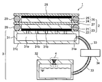
- Sectional drawing which shows an example of the fuel cell which has the pressure regulation valve for fuel cells of this invention.
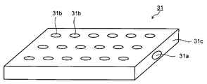
- the external view which shows an example of a fuel distribution mechanism.
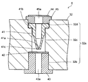
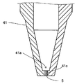
- Sectional drawing which shows an example of the pressure regulation valve for fuel cells which has a duckbill valve.
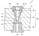
- Sectional drawing which shows the state which the opening-and-closing part of the pressure regulation valve for fuel cells shown in FIG. 3 opened.
- Sectional drawing which shows an example which provided the coating film which consists of a lubricant as an adhesion suppression means in a duckbill valve.
- Sectional drawing which shows an example which made the duck bill valve contain resin which has lubricity as an adhesion suppression means.
- Sectional drawing which shows the example which provided the pressure regulation valve for fuel cells above the liquid level of the liquid fuel.
- Sectional drawing which shows the example which provided the pressure regulation valve for fuel cells below the liquid level of the liquid fuel.
- Sectional drawing which shows an example of the pressure regulation valve for fuel cells which has an umbrella valve.
- Sectional drawing which shows the state which the opening-and-closing part of the pressure regulation valve for fuel cells shown in FIG. 9 opened.
- Sectional drawing which shows an example which provided the coating film which consists of a lubricant as an adhesion suppression means in the pressure regulation valve for fuel cells shown in FIG.
- Sectional drawing which shows the other example which provided the coating film which consists of a lubricant as an adhesion suppression means in the pressure regulation valve for fuel cells shown in FIG.
- FIG. 10 is a cross-sectional view showing an example in which a resin having lubricity is contained as an adhesion suppressing means in the pressure adjustment valve for a fuel cell shown in FIG. 9.
- Sectional drawing which shows the other example which made the pressure regulation valve for fuel cells shown in FIG. 9 contain resin which has lubricity as an adhesion suppression means.
- FIG. 16 is a cross-sectional view showing a state in which an opening / closing part of the fuel cell pressure regulating valve shown in FIG. 15 is opened.
- FIG. 16 is a cross-sectional view illustrating an example in which a resin having lubricity is contained as an adhesion suppressing unit in the fuel cell pressure regulating valve illustrated in FIG. 15.
- Sectional drawing which shows the other example which made the pressure regulation valve for fuel cells shown in FIG. 15 contain resin which has lubricity as an adhesion suppression means.
- FIG. 23 is a cross-sectional view showing a state where an opening / closing part of the umbrella valve unit shown in FIG. 22 is opened.
- Sectional drawing which shows an example of the pressure regulation valve which has two umbrella valve units.
- Sectional drawing which shows an example of the pressure control valve which has a duckbill valve and an umbrella valve.
- FIG. 26 is a cross-sectional view showing a state where an opening / closing part of the pressure regulating valve shown in FIG. 25 is opened.
- FIG. 28 is a cross-sectional view showing a state where an opening / closing part of the pressure regulating valve shown in FIG. 27 is opened.
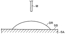
- the figure for demonstrating the measuring method of a contact angle The figure for demonstrating one process for measuring a contact angle.
- the figure for demonstrating one process for measuring a contact angle The figure for demonstrating one process for measuring a contact angle.
- the figure for demonstrating one process for measuring a contact angle. The
- FIG. 1 is a cross-sectional view showing an example of a fuel cell provided with a pressure regulating valve for a fuel cell of the present invention.
- the fuel cell 1 includes a fuel cell 2 that constitutes an electromotive unit, and a fuel supply mechanism 3 that supplies fuel to the fuel cell 2.
- the fuel supply mechanism 3 includes, for example, a fuel distribution mechanism 31 as shown in FIG. 2, a fuel storage portion 32 that stores liquid fuel, a flow path 33 that connects the fuel distribution mechanism 31 and the fuel storage portion 32, and And a pump 34 disposed in the flow path 33.
- the fuel cell pressure regulating valve 4 of the present invention (hereinafter simply referred to as the pressure regulating valve 4) is provided in the fuel accommodating portion 32 of the fuel supply mechanism 3.
- the pressure adjustment valve 4 suppresses leakage of liquid fuel from the inside of the fuel storage portion 32 to the outside, and from the outside to the inside when the internal pressure of the fuel storage portion 32 becomes a predetermined negative pressure state with respect to atmospheric pressure. It is provided in order to prevent air from being excessively reduced by introducing air into the head.
- Such a pressure regulating valve 4 is an openable / closable opening / closing part that suppresses leakage of liquid fuel from the inside of the fuel storage part 32 to the outside and enables introduction of air from the outside to the inside of the fuel storage part 32. have.
- the leakage of liquid fuel from the inside to the outside is suppressed by closing the opening / closing portion until the internal pressure of the fuel storage portion 32 reaches a predetermined negative pressure state with respect to the atmospheric pressure.
- the open / close portion is opened to introduce air from the outside to the inside.
- the internal pressure of the fuel storage portion 32 when the opening / closing portion is opened will be referred to as a valve opening pressure.
- the valve opening pressure can be arbitrarily set from pressures lower than the atmospheric pressure, but is preferably an arbitrary pressure up to about 0.1 MPa lower than the atmospheric pressure. That is, when the internal pressure of the fuel storage portion 32 becomes excessively low such that it exceeds 0.1 MPa with respect to the atmospheric pressure, the substantial liquid feeding capacity of the pump 34 is reduced, and the liquid fuel to the fuel cell 2 is reduced. It becomes difficult to adjust the supply amount appropriately, and the output characteristics of the fuel cell 1 are significantly deteriorated.
- the opening / closing portion is reliably opened when the internal pressure of the fuel storage portion 32 reaches the valve opening pressure. It is possible to suppress the internal pressure from excessively decreasing. As a result, the substantial liquid feeding capability of the pump 34 can be maintained, and the output characteristics of the fuel cell 1 can be improved by appropriately adjusting the amount of liquid fuel supplied to the fuel cell 2. .
- the adhesion suppressing means is not limited to the contact part of the opening / closing part, and may be provided in other parts including the contact part, for example, the entire members constituting the opening / closing part. Further, the adhesion suppressing means may be formed on the surface of the contact part of the opening / closing part, that is, the surface of the member constituting the opening / closing part, such as a coating film made of a lubricant or a coating made of resin or metal. Alternatively, for example, it may be a resin having lubricity contained in the contact portion of the opening / closing portion, that is, in the member constituting the opening / closing portion.
- FIG. 3 is a cross-sectional view showing an example of a pressure regulating valve 4 having a duckbill valve.
- the pressure regulating valve 4 includes a through hole 32a provided in the outer wall of the fuel storage portion 32, a duckbill valve 41 disposed in the through hole 32a, and a filter 42 fitted in each of the inner side and the outer side of the through hole 32a. And an outer side fixing member 45 having a filter 44.
- the through hole 32a is formed so as to penetrate the outer wall of the fuel storage portion 32.
- the inner side hole portion 32b provided on the inner side
- the outer side hole portion 32d provided on the outer side, and a gap therebetween. It is provided and has an intermediate hole 32c having a smaller diameter than these.
- An inner side fixing member 43 having a filter 42 and an outer side fixing member 45 having a filter 44 are fixed to the inner side holes 32b and 32d, respectively.
- the inner side fixing member 43 has a hole 43a for introducing air into the axial center, and the filter 42 is disposed on the outer side of the hole 43a.
- the external fixing member 45 also has a hole 45a for introducing air into the axial center, and the filter 44 is also arranged outside the hole 45a.
- the filter 42 and the filter 44 are provided in order to prevent foreign matter from entering the fuel storage portion 32 and to prevent the foreign matter from being completely closed by being sandwiched by the duckbill valve 41.
- Such a fuel storage portion 32 is preferably made of a resin material having resistance to liquid fuel, particularly methanol resistance.
- a resin material having resistance to liquid fuel particularly methanol resistance.
- PP polypropylene
- PPS polyphenylene sulfide
- HDPE high density polyethylene
- PS polystyrene
- PEEK Polyether ether ketone
- LCP liquid crystal polymer
- PBT polybutylene terephthalate
- POM polyacetal
- Phthalate polyethylene terephthalate (PET), cyclic olefin copolymer (COC), cycloolefin polymer (COP), polymethylpentene (TPX), polyphenylsulfone (PPSU), polyethersulfur It is preferably made of emissions (PES) and the like.
- the inner side fixing member 43 and the outer side fixing member 45 are also preferably made of a resin material having resistance to liquid fuel, particularly methanol resistance, such as polypropylene (PP), polyphenylene sulfide (PPS), and high density polyethylene. (HDPE), polystyrene (PS), polyetheretherketone (PEEK: trademark of Victorex), liquid crystal polymer (LCP), polybutylene terephthalate (PBT), polyacetal (POM), etc.
- PP polypropylene
- PPS polyphenylene sulfide
- HDPE polystyrene
- PEEK polyetheretherketone
- LCP liquid crystal polymer
- PBT polybutylene terephthalate
- POM polyacetal
- the resin material having polyethylene naphthalate (PEN), polyethylene terephthalate (PET), cyclic olefin copolymer (COC), cycloolefin polymer (COP), polymethylpentene (TPX), polyphenylsulfone ( PSU), preferably made of polyether sulfone (PES) and the like.
- PEN polyethylene naphthalate
- PET polyethylene terephthalate
- COC cyclic olefin copolymer
- COP cycloolefin polymer
- TPX polymethylpentene
- PSU polyphenylsulfone
- the inner side fixing member 43 and the outer side fixing member 45 are preferably made of the same material as that of the fuel storage portion 32, so that the fixing to the fuel storage portion 32 by ultrasonic bonding or the like becomes favorable.
- a gas-liquid separator that transmits only gas and does not transmit liquid is preferably used.
- LDPE low density polyethylene
- HDPE high density polyethylene
- PP Olefin resins such as (polypropylene)
- polyester resins such as PET (polyethylene terephthalate)
- fluororesins such as PTFE (polytetrafluoroethylene)
- porous bodies, membranes, or foams of urethane resins such as polyurethane.
- urethane resins such as polyurethane.
- the filter 42 and the filter 44 are made of a gas-liquid separator that allows only such gas to pass therethrough and does not allow liquid to pass therethrough, the liquid fuel can be prevented from leaking outside in the liquid state, and more safe. It can be made excellent.
- the filter 42 that is on the inner side of the opening / closing part such as the duckbill valve 41 is made of the gas-liquid separator described above, so that the liquid fuel is prevented from coming into direct contact with the opening / closing part. Deterioration due to adhesion or swelling of the opening / closing part due to contact can be suppressed.
- the duckbill valve 41 has an end that opens to the outside, and an end that closes and closes gradually toward the inside.
- a slit portion 41a having a negative (-) shape as viewed from the axial direction is formed at the closing end portion disposed on the inner side.
- a flange portion 41b is formed around the open end portion disposed on the outside side, a step portion formed between the intermediate hole portion 32c and the external side hole portion 32d, and an external side fixing member 45 and is fixed by being sandwiched between them.
- the duckbill valve 41 is made of an elastic material and is preferably made of ethylene-propylene-diene rubber (EPDM) having resistance to liquid fuel, particularly methanol resistance.
- EPDM ethylene-propylene-diene rubber
- silicone rubber VMQ
- FVMQ fluorosilicone rubber
- FKM fluorine rubber
- NBR nitrile rubber
- HNBR hydrogenated nitrile rubber
- the slit portion 41 a of the duckbill valve 41 is closed, so that the liquid fuel is transferred from the inside of the fuel storage portion 32 to the outside. Leakage is suppressed.
- the slit part 41a is opened as shown in FIG.
- the slit portion 41a of the duckbill valve 41 corresponds to an opening / closing portion
- the inner surface 41c of the slit portion 41a corresponds to a contact portion of the opening / closing portion.
- the adhesion suppression means 5 is provided in the inner surface 41c of the slit part 41a corresponded to the contact part of an opening-and-closing part.
- the adhesion suppressing means 5 may be provided on the inner surface 41c of the slit portion 41a, for example, as shown in FIG. 5, it may be provided as a coating film made of a lubricant on the surface of the inner surface 41c, or for example, as shown in FIG. You may provide by making it contain in 41c as resin which has lubricity. As shown in FIG. 6, when a resin having lubricity is contained, it is usually contained in a granular form.
- the adhesion suppressing means 5 In the case where a coating film made of a lubricant is provided as the adhesion suppressing means 5, for example, as shown in FIG. 5, it is provided only on the inner surface 41c of the slit portion 41a, and although not shown, for example, the entire inner surface and outer surface of the duckbill valve 41 May be provided. Further, in the case where a resin having lubricity is contained as the adhesion suppressing means 5, for example, it is contained in the entire duckbill valve 41 as shown in FIG. 6, but it is contained only in the peripheral portion of the inner surface 41c of the slit portion 41a although not shown. You may let them.
- the slit portion 41a can be surely opened when the internal pressure of the fuel storage portion 32 reaches the valve opening pressure, and the air from the outside to the inside It can suppress that an internal pressure falls excessively by introduce
- the slit portion 41a can be reliably closed even when such an adhesion suppressing means 5 is provided, and when the internal pressure of the fuel storage portion 32 has not reached the valve opening pressure, the liquid fuel leaks from the inside to the outside. Can be suppressed.
- lubricant used for forming the coating film as the adhesion suppressing means 5 include at least one lubricant selected from, for example, a fluorine-based lubricant, a silicone-based lubricant, and an olefin-based lubricant. Are mentioned as preferred.
- fluorine-based lubricant examples include known fluorine oils.
- perfluoropolyether represented by the following chemical formula (1) or ethylene trifluoride chloride low polymer represented by the following chemical formula (2) is suitable. As mentioned.
- R and R ′ are perfluoroalkyl groups or oxyperfluoroalkyl groups
- p, q and r are positive integers, and up to two of them may be 0.
- p + q + r is liquid or normal temperature. (To be greased.)
- n is determined to be liquid or grease-like at normal temperature.
- silicone-based lubricant examples include known silicone oils, such as dimethyl silicone oil, methylphenyl silicone oil, methyl hydrogen silicone oil, and modified products thereof (for example, amino-modified and alkyl-modified). .
- examples of the olefinic lubricant include known olefinic oils such as polyethylene, polypropylene, ethylene-propylene copolymer, ethylene-butene copolymer, ethyleneoctene copolymer, polypropylene-butene copolymer, Liquid or grease at room temperature comprising polybutene, ethylene-acrylic acid ester copolymer, ethylene-methacrylic acid ester copolymer, ethylene-acrylic acid copolymer, ethylene-vinyl acetate copolymer, etc., or modified products thereof It is a shape.
- known olefinic oils such as polyethylene, polypropylene, ethylene-propylene copolymer, ethylene-butene copolymer, ethyleneoctene copolymer, polypropylene-butene copolymer, Liquid or grease at room temperature comprising polybutene, ethylene-acrylic acid ester copolymer, ethylene-me
- the lubricant in order to suppress a decrease in output characteristics due to mixing of impurities such as metal ions into the fuel battery cell 2, refined oil purified so as to suppress elution of impurities, or such A diluted purified oil obtained by diluting a purified oil with an organic solvent is preferred.
- refined oil include refined oils obtained by purifying the above-described fluorine oil, silicone oil, and olefin oil.
- Such a coating film can be formed by applying a lubricant to the inner surface 41c of the slit portion 41a by applying a known method such as a dipping method, a brush coating method, or a spray coating method.
- the coating amount of the lubricant is preferably, for example, 0.001 mg / cm 2 or more 0.100 mg / cm 2 or less. When the application amount of the lubricant is less than 0.001 mg / cm 2 , the adhesion of the slit portion 41a may not be sufficiently suppressed.
- the coating amount of the lubricant is about 0.100 mg / cm 2 , the durability of the coating film can be secured, and if it exceeds that, the lubricant may flow out and be mixed into the fuel storage portion 32, which is not preferable.
- examples of the resin having lubricity to be contained as the adhesion suppressing means 5 include a fluorine resin, a silicone resin, an olefin resin, and a urethane resin.
- fluorine resins include tetrafluoroethylene resin, tetrafluoroethylene-perfluoroalkoxyethylene copolymer resin, tetrafluoroethylene-hexafluoropropylene copolymer resin, tetrafluoroethylene-hexafluoropropylene-per Examples thereof include fluoroalkoxyethylene copolymer resins, ethylene tetrafluoride-ethylene copolymer resins, ethylene trifluoride chloride resins, ethylene trifluoride chloride-ethylene copolymer resins, vinylidene fluoride resins, and vinyl fluoride resins.
- silicone-based resin examples include resins such as dimethylpolysiloxane having a siloxane skeleton and methylphenylpolysiloxane, and modified products thereof (for example, amino-modified and alkyl-modified).
- the olefin resin examples include polyethylene resin, polypropylene resin, ethylene-propylene copolymer resin, ethylene-butene copolymer resin, ethylene octene copolymer resin, polypropylene-butene copolymer resin, polybutene resin, ethylene-acrylic ester copolymer.
- examples thereof include resins, ethylene-methacrylic acid ester copolymer resins, ethylene-acrylic acid copolymer resins, ethylene-vinyl acetate copolymer resins, and modified products thereof.
- examples of the urethane resin include polyurethane resins obtained by copolymerizing monomers with urethane bonds formed mainly by condensation of isocyanate groups and alcohol groups, or modified products thereof.
- a method of adding a resin having lubricity for example, a method of adding a resin having lubricity when manufacturing the duckbill valve 41, that is, adding a resin having lubricity to the raw material used for manufacturing the duckbill valve 41 The method of manufacturing by shape
- the inner surface 41c of the slit portion 41a provided with such an adhesion suppressing means 5 has low wettability with respect to the liquid fuel stored in the fuel storage portion 32.
- the inner surface 41c of the slit part 41a provided with the adhesion suppression means 5 means the surface of the coating film made of this lubricant when a coating film made of a lubricant is provided as the adhesion suppression means 5.
- a resin having lubricity is contained as the adhesion suppressing means 5, it means the inner surface 41c of the slit portion 41a containing the resin having lubricity.
- the sticking of the slit portion 41a is caused by a release agent or the like flowing out from the inside.
- a release agent or the like flowing out from the inside.
- the contact area can be reduced, and the outflow itself of the release agent or the like causing the adhesion can be suppressed.
- the liquid fuel can be substantially spherical, and the contact area can be further reduced.
- the contact angle generally means the angle between the tangent to the liquid layer surface and the solid-liquid contact surface at the three-layer contact point of the solid-liquid gas when the liquid layer is in contact with the surface of the solid layer.
- the inner surface 41c of the slit portion 41a having the adhesion suppressing means 5 corresponds to a solid layer, and the liquid fuel corresponds to a liquid layer.
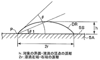
- the specific method for measuring the contact angle is as follows. That is, as shown in FIG. 29, the contact angle ⁇ of the droplet DR made of liquid fuel with respect to the member to be measured 5A (the member provided with the adhesion suppressing means 5) is the point at which the droplet DR and the member to be measured 5A contact each other. This is the angle formed by the tangent to the surface curve of the droplet DR at P and the surface 5S of the member to be measured 5A.
- a contact angle meter (DropMaster 100), a solid-liquid interface analyzing device (DropMaster 500), and a measurement analysis integrated system software (FAMAS: 2004/7) manufactured by Kyowa Interface Science Co., Ltd. are used.
- FAMAS measurement analysis integrated system software
- a liquid fuel droplet DR is formed with a microsyringe M (Teflon (registered trademark) coated needle 28G ( ⁇ 0.1 mm)).
- the droplet DR is about 0.5 microliter, for example.
- the bottom of the droplet DR is brought into contact with the surface 5S of the measurement target member 5A.
- a droplet DR as shown in FIG. 32 adheres to the surface 5S of the member to be measured 5A.
- the height h of the droplet DR and the radius r of the droplet DR are measured.
- Such wettability is adjusted by selecting the type of lubricant from the above-mentioned lubricants and adjusting the coating amount when the adhesion suppressing means 5 is a coating film made of a lubricant.
- the type of resin having lubricity is selected from the resins having lubricity and the content is adjusted. Can do.
- the pressure adjustment valve 4 whose opening / closing portion is the duckbill valve 41 has been described.
- the pressure adjustment valve 4 is disposed in any part of the fuel storage portion 32.
- it may be arranged mainly at a position above the liquid level of the liquid fuel, or it may be arranged at a position mainly below the liquid level although not shown.
- a filter 42 made of a gas-liquid separator that allows only gas to permeate to the inner side (liquid fuel side) of the opening / closing part (for example, the duckbill valve 41) of the pressure regulating valve 4 and does not permeate liquid. If arranged, even if the pressure regulating valve 4 is arranged below the liquid level, air can be introduced when necessary while suppressing leakage of the liquid fuel.
- the pressure regulating valve 4 is not necessarily provided with the filter 42 or the filter 44 made of a gas-liquid separator, and in such a case, it is mainly above or below the liquid level of the liquid fuel. It can arrange
- the pressure regulating valve 4 when the pressure regulating valve 4 is disposed mainly at a position above the liquid level of the liquid fuel, air can be directly introduced to the pressure regulating valve 4 as well as air can be introduced when necessary. Therefore, the liquid fuel can be prevented from leaking in the liquid state even without the filter 42 made of the gas-liquid separator as shown in FIG. 3, and the pressure regulating valve 4 by the contact of the liquid fuel can be suppressed. Deterioration due to adhesion or swelling of the opening / closing part can also be suppressed.
- the slit portion 41a is provided with a lubricant, particularly a liquid-repellent material that repels liquid fuel, so that only air can be effectively suppressed while suppressing leakage of liquid fuel. Can be introduced.
- a lubricant particularly a liquid-repellent material that repels liquid fuel
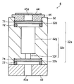
- FIG. 9 is a cross-sectional view showing the pressure adjustment valve 4 using the umbrella valve 51.
- This pressure regulating valve 4 is also similar to the pressure regulating valve 4 using the duckbill valve 41 shown in FIG. 3, and includes a through hole 32a having an inner side hole 32b, an intermediate hole 32c, and an outer side hole 32d.
- the inner side fixing member 43 having the filter 42 and the outer side fixing member 45 having the filter 44 are provided.
- the inner side fixing member 43 is fitted so that a space remains in the inner side hole 32b, and the outer side fixing member 45 is also fitted so that a space remains in the outer side hole 32d.
- the umbrella valve 51 is disposed inside the through-hole 32a, and an umbrella-shaped main body 51a is disposed in a space formed by the inner-side hole 32b and the inner-side fixing member 43.
- a shaft portion 51b extending in the middle is inserted into the intermediate hole portion 32c.
- a flange 51c is formed on the shaft 51b so as to overlap at least a part of the intermediate hole 32c, and the umbrella valve 51 is fixed by press-fitting and fixing the flange 51c into the intermediate hole 32c.
- an air flow path that is a groove portion along the axial direction is formed in the side surface portion of the flange portion 51c, and air is supplied from between the intermediate hole portion 32c press-fitted and fixed through the air flow channel and the flange portion 51c. It can be introduced.
- the umbrella valve 51 is made of, for example, an elastic material, and as such, it is preferably made of ethylene-propylene-diene rubber (EPDM) having resistance to liquid fuel, particularly methanol resistance.
- EPDM ethylene-propylene-diene rubber
- VMQ fluorosilicone rubber
- FKM fluorine rubber
- NBR nitrile rubber
- HNBR hydrogenated nitrile rubber
- the step part 32e formed between the internal side hole part 32b and the intermediate hole part 32c of the through-hole 32a, the umbrella valve 51, specifically the umbrella-shaped main-body part 51a,
- the opening / closing part is constituted by the contact part of the step part 32e and the umbrella-shaped main body part 51a.
- the step portion 32e serves as a valve seat
- the intermediate hole portion 32c serves as a passage hole for the valve seat.
- the adhesion suppression means 5 is provided in at least one chosen from the contact part of the step part 32e equivalent to the contact part of an opening-and-closing part and the umbrella-shaped main-body part 51a.
- a coating film made of a lubricant may be provided on the surface of the stepped portion 32e as shown in FIG. 11, or the surface of the umbrella-shaped main body portion 51a as shown in FIG.
- a coating film made of a lubricant may be provided on the surface of the outer edge.
- a resin having lubricity may be contained in the step portion 32e, and for example, a resin having lubricity is contained in the inside of the umbrella-shaped main body 51a as shown in FIG. You may make it contain.
- the coating film which consists of lubricants as the adhesion suppression means 5, for example, as shown to FIG. 11, 12, other than providing in the surface part which actually contacts the step part 32e and the umbrella-shaped main-body part 51a, although not shown in figure.
- it may be provided on the entire inner surface of the through hole 32 a or the entire surface of the umbrella valve 51.
- a resin having lubricity is included as the adhesion suppressing means 5, for example, as shown in FIGS. 13 and 14, the step 32e and the umbrella-shaped main body 51a are contained in the entire interior. 32e and the umbrella-like main body 51a may be contained only in the vicinity of the surface.
- the umbrella valve 51 can be reliably secured when the internal pressure of the fuel storage portion 32 reaches the valve opening pressure.
- Umbrella-shaped main body 51a in particular, the outer peripheral portion can be deformed so as to be slightly lifted from stepped portion 32e to open intermediate hole portion 32c, and the internal pressure is excessively reduced by introducing air from the outside to the inside. This can be suppressed.
- the intermediate hole portion 32c opened to the step portion 32e can be reliably closed by the umbrella-shaped main body portion 51a, and the internal pressure of the fuel storage portion 32 reaches the valve opening pressure. When not, leakage of the liquid fuel from the inside of the fuel storage portion 32 to the outside can be suppressed.
- Such a coating film made of a lubricant as the adhesion suppressing means 5 and a resin having lubricity are the same as the coating film made of a lubricant provided on the duckbill valve 41 and a resin having lubricity.
- the forming method can be the same.
- a resin coating or a metal coating may be used instead of a coating film made of a lubricant.
- Suitable examples of the resin coating include those made of at least one resin selected from a fluorine resin, a silicone resin, an olefin resin, and a urethane resin.
- fluorine resins include tetrafluoroethylene resin, tetrafluoroethylene-perfluoroalkoxyethylene copolymer resin, tetrafluoroethylene-hexafluoropropylene copolymer resin, tetrafluoroethylene-hexafluoropropylene-per Examples thereof include fluoroalkoxyethylene copolymer resins, ethylene tetrafluoride-ethylene copolymer resins, ethylene trifluoride chloride resins, ethylene trifluoride chloride-ethylene copolymer resins, vinylidene fluoride resins, and vinyl fluoride resins.
- silicone-based resin examples include resins such as dimethylpolysiloxane having a siloxane skeleton and methylphenylpolysiloxane, and modified products thereof (for example, amino-modified and alkyl-modified).
- the olefin resin examples include polyethylene resin, polypropylene resin, ethylene-propylene copolymer resin, ethylene-butene copolymer resin, ethylene octene copolymer resin, polypropylene-butene copolymer resin, polybutene resin, ethylene-acrylic ester copolymer.
- examples thereof include resins, ethylene-methacrylic acid ester copolymer resins, ethylene-acrylic acid copolymer resins, ethylene-vinyl acetate copolymer resins, and modified products thereof.
- examples of the urethane resin include polyurethane resins obtained by copolymerizing monomers with urethane bonds formed mainly by condensation of isocyanate groups and alcohol groups, or modified products thereof.
- the resin coating can be formed, for example, by applying a liquid material of the resin material to the surface of the stepped portion 32e and curing it by heat treatment.
- the method for applying the liquid material is not particularly limited, and a known method such as a brush coating method or a spray coating method can be employed.
- the heat treatment is preferably performed at a temperature commensurate with the resin material, and is generally preferably performed at 100 ° C. or higher and 450 ° C. or lower.
- the liquid material application and the heat treatment may be performed only once, or may be repeated a plurality of times.
- the thickness of the resin coating is not necessarily limited, but is preferably 10 nm or more and 500 ⁇ m or less, and more preferably 50 nm or more and 100 ⁇ m or less.
- the thickness of the resin coating is less than 10 nm, the adhesion between the stepped portion 32e and the umbrella-shaped main body portion 51a may not be sufficiently suppressed.
- the thickness of the resin coating is about 500 ⁇ m, the adhesion between the stepped portion 32e and the umbrella-shaped main body 51a can be sufficiently suppressed, and if it exceeds that, it takes time to form the resin coating. This is not preferable because the properties are lowered.
- the metal coating is preferably made of gold or a gold alloy, or titanium or a titanium alloy because of excellent lubricity.
- the thickness of a metal coating is not necessarily limited, Preferably it is 10 nm or more and 500 micrometers or less, More preferably, it is 50 nm or more and 100 micrometers or less.
- the metal coating can be formed using, for example, a sputtering method, a vapor deposition method, an electrolytic or electroless plating method, or the like.
- At least one resin selected from a fluorine resin, a silicone resin, an olefin resin, and a urethane resin is added to at least one metal selected from gold or a gold alloy, or titanium or a titanium alloy.
- a resin coating, a metal coating or the like it is preferable to perform a polishing process on the surface of the stepped portion 32e, and it is particularly preferable to perform a polishing process so that the surface roughness Ra is 3.2 ⁇ m or less.
- polishing the surface of the stepped portion 32e in particular, polishing so that the surface roughness Ra is within the above range, the surface of the resin coating or metal coating to be formed thereafter is smoothed and further adhered. It can be difficult.
- Such a polishing process is not particularly limited, and various polishing processes such as a buff polishing process, a barrel polishing process, an electrolytic polishing process, a chemical polishing process, and a magnetic polishing process can be applied.
- the surface roughness Ra is the arithmetic average roughness Ra, and the value of the arithmetic average roughness Ra is represented by 3 “Definition and display of defined arithmetic average roughness” of JIS: B0601 (1994). It has been done.
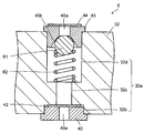
- FIG. 15 is a cross-sectional view showing the pressure regulating valve 4 using the ball valve 61.
- the pressure regulating valve 4 also has a through hole 32a having an inner side hole 32b, an intermediate hole 32c, and an outer side hole 32d in substantially the same manner as the pressure regulating valve 4 using the umbrella valve 51 shown in FIG.
- the inner side fixing member 43 having the filter 42 and the outer side fixing member 45 having the filter 44 are provided.
- the outer side hole 32d and the outer side fixing member 45 are shaped such that a space is left in the outer side hole 32d.
- the hole 45a of the outer side fixing member 45 has, for example, a diameter-expanded portion 45b that gradually increases in diameter toward the inner side.
- the ball valve 61 is disposed in a space formed by the outer hole portion 32d and the outer fixing member 45, and is pressed by the enlarged diameter portion 45b of the outer fixing member 45 by an elastic body 62 such as a compression spring. Yes.
- the ball valve 61 is made of, for example, an elastic material, and as such, the ball valve 61 is preferably made of ethylene-propylene-diene rubber (EPDM) having resistance to liquid fuel, particularly methanol resistance.
- EPDM ethylene-propylene-diene rubber
- VMQ fluorosilicone rubber
- FKM fluorine rubber
- NBR nitrile rubber
- HNBR hydrogenated nitrile rubber
- the elastic body 62 is also preferably subjected to a surface treatment in order to have excellent methanol resistance, and specifically, a passivation treatment is performed on a stainless steel compression spring, Those having excellent corrosion resistance are preferred.
- the surface treatment is not limited to the passivation treatment, and a precious metal plating such as gold or a resin coating such as a fluorine-based resin is also preferably used. Also, a spring using carbon as a material can be used.
- the opening / closing portion 4a is constituted by the enlarged diameter portion 45b of the external fixing member 45 and the ball valve 61, and the ball valve 61 of the enlarged diameter portion 45b is in contact therewith, that is, the enlarged diameter portion 45b.
- the surface portion in contact with the surface portion of the ball valve 61 in contact with the enlarged diameter portion 45b is a contact portion of the opening / closing portion.
- the enlarged diameter portion 45b is a valve seat closed by the ball valve 61, and the hole 45a of the external fixing member 45 is a flow passage hole of the valve seat.
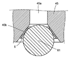
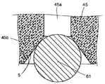
- the adhesion suppression means 5 is provided in at least one chosen from the contact parts of the enlarged diameter part 45b and the ball valve 61 corresponded to the contact part of an opening-and-closing part.
- a coating film made of a lubricant may be provided on the surface of the enlarged diameter portion 45b as shown in FIG. 17, or the surface of the ball valve 61 is lubricated as shown in FIG. You may provide the coating film which consists of an agent.
- a resin having lubricity may be contained in the enlarged diameter portion 45b as shown in FIG. 19, or a resin having lubricity is contained in the ball valve 61 as shown in FIG. You may let them.
- the adhesion suppressing means 5 When a coating film made of a lubricant is provided as the adhesion suppressing means 5, for example, as shown in FIG. 17, it is provided only on the surface portion of the enlarged diameter portion 45b that actually contacts the ball valve 61. You may provide in the whole surface of the diameter part 45b. Further, when a resin having lubricity is contained as the adhesion suppressing means 5, for example, the resin may be contained in the entire enlarged diameter portion 45 b or the outer side fixing member 45, and although not shown, for example, near the surface of the enlarged diameter portion 45 b. You may make it contain only inside. Moreover, as the adhesion suppression means 5 provided in the surface of the enlarged diameter part 45b, it is good also as a resin coating or a metal coating instead of the coating film consisting of a lubricant.
- the ball valve 61 By providing the adhesion suppressing means 5 in at least one selected from the contact portions between the enlarged diameter portion 45b and the ball valve 61, the ball valve 61 can be reliably moved when the internal pressure of the fuel storage portion 32 reaches the valve opening pressure. It can be moved to the inner side to open the enlarged diameter portion 45b, and the introduction of air from the outside to the inside can prevent the internal pressure from excessively decreasing. On the other hand, even when such adhesion suppressing means 5 is provided, the enlarged diameter portion 45b can be reliably closed by the ball valve 61, and when the internal pressure of the fuel storage portion 32 has not reached the valve opening pressure, the fuel storage portion 32 is provided. The leakage of the liquid fuel from the inside to the outside can be suppressed.
- the coating film made of the lubricant as the adhesion suppressing means 5 and the resin having lubricity are the same as the coating film made of the lubricant provided on the duckbill valve 41 and the resin having lubricity.
- the formation method can be the same.
- the resin coating or metal coating as the adhesion suppressing means 5 can be the same as the resin coating or metal coating provided on the step portion 32e of the pressure regulating valve 4 using the umbrella valve 51 described above.
- the formation method can also be the same.
- the pressure regulating valve 4 of the present invention has been described by taking as an example one having one valve body, that is, one having an opening / closing portion.
- air is introduced.
- What has two or more valve bodies in series with respect to a direction ie, what should be called a balance valve unit which has two or more opening-closing parts, may be used.
- the adhesion suppressing means 5 may be provided in an opening / closing part related to either the internal or external valve body, but since the liquid fuel in the fuel storage part 32 comes into contact and easily adheres, at least the internal It is preferable that it is provided in the opening / closing part which concerns on the side valve body.
- the pressure regulating valve 4 having two or more valve bodies will be specifically described.
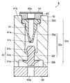
- FIG. 21 is a cross-sectional view showing the pressure regulating valve 4 having the duckbill valve 41 and the umbrella valve unit 71.
- This pressure adjustment valve 4 is substantially the same as the pressure adjustment valve 4 shown in FIG. 3 except that an umbrella valve unit 71 is further arranged inside the duckbill valve 41.
- the intermediate hole portion 32c is composed of a small diameter portion 32f and a large diameter portion 32g disposed on the outside side.
- the inner side fixing member 43 is not fitted into the inner side hole portion 32b, and is fixed to the periphery thereof by ultrasonic welding or the like.
- the umbrella valve unit 71 has, for example, a flat outer shape, and is fixed to the inner side hole 32b so as to be pressed against the inner side fixing member 43 via a rubber O-ring 72.
- FIG. 22 is an enlarged sectional view showing the umbrella valve unit 71.
- the umbrella valve unit 71 includes, for example, an umbrella valve 51 and a holding member 72 that holds the umbrella valve 51 inside.
- the umbrella valve unit 71 has a laminated structure in which a space forming material 75 made of the same PET or the like is arranged in a frame shape between a pair of plate materials 73 and 74 made of, for example, PET (polyethylene terephthalate). It has a space 76 inside.
- Such an umbrella valve unit 71 is preferably made of a resin material having resistance to liquid fuel, particularly methanol resistance.
- polypropylene PP
- polyphenylene sulfide PPS
- high density polyethylene HDPE
- polystyrene PS
- Polyetheretherketone PEEK: trademark of Victorex
- liquid crystal polymer LCP
- PBT polybutylene terephthalate
- POM polyacetal
- Phthalate polyethylene terephthalate (PET), cyclic olefin copolymer (COC), cycloolefin polymer (COP), polymethylpentene (TPX), polyphenylsulfone (PPSU), polyether Preferably consists Rusaruhon (PES) and the like.
- An introduction hole 74 a for introducing air from the outside to the space 76 is provided in the plate member 74 that is on the outside.
- plate material 73 used as an inner side is provided with the discharge hole 73a for discharging
- a pair of recessed parts 73b and 74b are formed in the substantially center part of the main surface which becomes the space part 76 side of each board
- the umbrella valve 51 has substantially the same structure as that of the umbrella valve 51 as shown in FIG. 9, although the specific shape and size are different.
- the umbrella valve 51 has an umbrella-shaped main body 51a and a shaft 51b.
- the whole is made of silicone rubber or the like.
- the umbrella valve 51 is disposed in the space portion 76 with both end portions of the shaft portion 51b inserted into the pair of recess portions 73b and 74b so that the concave portion side of the umbrella-shaped main body portion 51a faces the outer plate member 74. Yes.
- an opening / closing portion is configured by a plate material 74 having an introduction hole 74 a, an umbrella valve 51, specifically, an umbrella-shaped main body portion 51 a, and the plate material 74 and the umbrella valve 51 include The part which contacts is the contact part of the opening / closing part.
- the surface of the plate member 74 on the space 76 side is a valve seat, and the introduction hole 74a is a flow hole for the valve seat.
- the adhesion suppression means 5 is provided in at least one selected from the contact part of the board
- the method of providing the adhesion suppression means 5 it can carry out like the case of the pressure regulation valve 4 which has the umbrella valve 51 as shown in FIG.
- the introduction hole 74a is closed by the umbrella-shaped main body portion 51a, so that liquid fuel leaks to the outside. It is suppressed.
- the introduction hole 74a is opened by deforming the umbrella-shaped main body 51a, particularly the outer peripheral portion, to slightly lift from the plate member 74 as shown in FIG.
- air is introduced into the space portion 73 from the outside through the introduction hole 74a, and air is discharged from the space portion 73 to the inside through the discharge hole 73a.
- the opening / closing part can be appropriately opened and closed in response to a slight pressure change between the outside and the inside. For this reason, by using together with the duckbill valve 41 etc., the leakage of liquid fuel can be suppressed more appropriately.
- the duckbill valve 41 since the pressure from the outside is basically applied so as to close the slit portion 41a, for example, even if the internal pressure of the fuel storage portion 32 is higher than the atmospheric pressure, It can be made safe by suppressing fuel leakage.
- the slit portion 41a when the slit portion 41a is changed from the open state to the closed state, the slit portion 41a may not necessarily close enough to use its own elastic deformation force, and the liquid fuel may leak. For this reason, leakage of liquid fuel can be more appropriately suppressed by using the umbrella valve unit 71 that can appropriately open and close the opening / closing portion in response to a slight pressure change.
- the umbrella valve unit 71 having a valve opening pressure of 0 to ⁇ 2 kPa is used.
- a valve having a valve opening pressure of ⁇ 2 to ⁇ 5 kPa can be used as the duckbill valve 41.
- FIG. 24 is a cross-sectional view showing the pressure regulating valve 4 using the two umbrella valve units 71 described above.
- This pressure regulating valve 4 uses an umbrella valve unit 71 in place of the duckbill valve 41 in the pressure regulating valve 4 shown in FIG. 21.
- a rubber O-ring 72 is provided in the outer side hole 32d.
- the umbrella valve unit 71 is disposed via the outer fixing member 45 and is fixed so as to be pressed by the external fixing member 45.
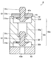
- FIG. 25 is a cross-sectional view showing the pressure regulating valve 4 having the duckbill valve 41 and the umbrella valve 51.
- This pressure adjusting valve 4 uses an umbrella valve 51 as shown in FIG. 9 instead of the umbrella valve unit 71 in the pressure adjusting valve 4 shown in FIG.
- the umbrella valve 51 also has an umbrella-shaped main body 51a, a shaft 51b, a flange 51c, and an air flow path (not shown) formed in the side surface along the axial direction.
- the shaft portion 51b is arranged so as to be inserted into the small diameter portion 32f so as to be on the inner side.
- the pressure adjusting valve 4 when the internal pressure of the fuel storage portion 32 does not reach the valve opening pressure, the small diameter portion 32 f is closed mainly by the umbrella valve 51 disposed on the inner side, whereby the liquid fuel to the outside is supplied. Leakage is suppressed. Further, by closing the slit portion 41a of the duckbill valve 41, leakage of liquid fuel to the outside is additionally suppressed.
- the umbrella valve 51 is deformed and the small diameter portion 32f is opened as shown in FIG. 26, so that the small diameter portion 32f is opened through the small diameter portion 32f. Air is introduced into the side hole 32b. In the small diameter portion 32f, air is introduced through an air flow path (not shown) formed on the side surface portion of the umbrella valve 51, for example. Further, when the slit portion 41a of the duckbill valve 41 is opened, air is introduced into the large diameter portion 32g from the outside, and a series of air introduction paths is formed.
- FIG. 27 is a cross-sectional view showing the pressure regulating valve 4 having two umbrella valves 51.
- This pressure regulating valve 4 uses an umbrella valve 51 as shown in FIG. 9 in place of the duckbill valve 41 in the pressure regulating valve 4 shown in FIG.
- the umbrella valve 51 disposed on the outer side also has an umbrella-shaped main body 51a, a shaft 51b, a collar 51c, and an air flow path (not shown) formed along the axial direction on the side surface.
- the umbrella-shaped main body 51a is arranged on the inner side, and the shaft 51b is inserted into the hole 45a of the outer fixing member 45.
- the pressure adjusting valve 4 when the internal pressure of the fuel storage portion 32 does not reach the valve opening pressure, the small diameter portion 32 f is closed mainly by the umbrella valve 51 disposed on the inner side, whereby the liquid fuel to the outside is supplied. Leakage is suppressed. Further, the hole 45a is closed by the umbrella valve 51 arranged on the outside side, so that leakage of liquid fuel to the outside side is additionally suppressed.
- the outer umbrella valve 51 is deformed and the hole 45a is opened as shown in FIG. Air is introduced into the external hole 32d. Further, when the umbrella valve 51 on the inner side is deformed and the small diameter portion 32f is opened, air is introduced from the large diameter portion 32g to the inner side hole portion 32b through the small diameter portion 32f. In the hole 45a and the small diameter portion 32f, air is introduced through an air flow path (not shown) formed on the side surface of the umbrella valve 51.
- the pressure regulating valve 4 having two or more valve bodies has been described above.
- the type of the valve body to be used is not particularly limited.
- valve elements to be arranged on the inner side and the outer side are not necessarily limited, but for those arranged on the inner side, the opening / closing part can be opened and closed appropriately in response to slight pressure changes.
- the above-described umbrella valve 51, ball valve 61, umbrella valve unit 71, etc. are preferable, and those arranged on the outside side have a strong force to suppress leakage of liquid fuel, that is, a strong check force
- an umbrella valve 51, a ball valve 61, an umbrella valve unit 71, and the like can be used, but the duckbill valve 41 is particularly preferable.
- liquid fuel may enter between the opening / closing parts. Depending on the case, this may leak to the outside. For this reason, it is preferable to increase the valve opening pressure of the opening / closing part disposed on the inner side, block the liquid fuel from entering between the opening / closing parts, and suppress leakage to the outside.
- the external opening and closing part can be opened almost simultaneously with the opening of the internal opening and closing, and at the end of the introduction,
- the internal opening / closing part can be closed first, and in any case, the ingress of liquid fuel can be reliably blocked by the internal opening / closing part, and leakage of the liquid fuel to the outside can be suppressed.
- valve opening pressure means the valve opening pressure for each opening / closing part
- the high valve opening pressure means that the valve does not open / close unless the pressure difference between both sides is relatively large. Specifically, it means that it is difficult to open at the start of air introduction and close easily at the end of introduction.
- the fuel cell 2 includes an anode 23 (fuel electrode) having an anode catalyst layer 21 and an anode gas diffusion layer 22, and a cathode 26 (with a cathode catalyst layer 24 and a cathode gas diffusion layer 25).
- Air electrode / oxidant electrode and a membrane electrode assembly (Mebrane Electrode Assembly: MEA) composed of a proton (hydrogen ion) conductive electrolyte membrane 27 sandwiched between the anode catalyst layer 21 and the cathode catalyst layer 24.
- MEA Membrne Electrode Assembly
- Examples of the catalyst contained in the anode catalyst layer 21 and the cathode catalyst layer 24 include simple substances of platinum group elements such as Pt, Ru, Rh, Ir, Os, and Pd, alloys containing the platinum group elements, and the like.
- the anode catalyst layer 21 is preferably made of Pt—Ru, Pt—Mo, or the like that has strong resistance to methanol, carbon monoxide, or the like.
- Pt, Pt—Ni or the like is preferably used for the cathode catalyst layer 24.
- the catalyst is not limited to these, and various substances having catalytic activity can be used.
- the catalyst may be either a supported catalyst using a conductive support such as a carbon material or an unsupported catalyst.
- Examples of the proton conductive material constituting the electrolyte membrane 27 include a fluorine-based resin such as a perfluorosulfonic acid polymer having a sulfonic acid group (Nafion (trade name, manufactured by DuPont) or Flemion (trade name, manufactured by Asahi Glass Co., Ltd.). Etc.), organic materials such as hydrocarbon resins having sulfonic acid groups, or inorganic materials such as tungstic acid and phosphotungstic acid.
- a fluorine-based resin such as a perfluorosulfonic acid polymer having a sulfonic acid group (Nafion (trade name, manufactured by DuPont) or Flemion (trade name, manufactured by Asahi Glass Co., Ltd.). Etc.
- organic materials such as hydrocarbon resins having sulfonic acid groups
- inorganic materials such as tungstic acid and phosphotungstic acid.
- the proton conductive electrolyte membrane 27
- the anode gas diffusion layer 22 laminated on the anode catalyst layer 21 serves to uniformly supply fuel to the anode catalyst layer 21 and also serves as a current collector for the anode catalyst layer 21.
- the cathode gas diffusion layer 25 laminated on the cathode catalyst layer 24 serves to uniformly supply an oxidant to the cathode catalyst layer 24 and also serves as a current collector for the cathode catalyst layer 24.
- the anode gas diffusion layer 22 and the cathode gas diffusion layer 25 are made of a porous substrate.
- a conductive layer is laminated on the anode gas diffusion layer 22 and the cathode gas diffusion layer 25 as necessary.
- these conductive layers for example, a porous layer (for example, a mesh) made of a conductive metal material such as Au or Ni, a thin film or a foil, or a conductive metal material such as stainless steel (SUS) or a highly conductive material such as Au.
- SUS stainless steel
- a metal-coated composite material or the like is used. Rubber O-rings 29 are interposed between the electrolyte membrane 27, the fuel distribution mechanism 31 and the cover plate 28, thereby preventing fuel leakage and oxidant leakage from the fuel cell (MEA) 2. is doing.
- the cover plate 28 has an opening for taking in air as an oxidant.
- a moisture retaining layer and a surface layer are disposed between the cover plate 28 and the cathode 26 as necessary.
- the moisturizing layer is impregnated with a part of the water generated in the cathode catalyst layer 24 to suppress the transpiration of water and promote uniform diffusion of air to the cathode catalyst layer 24.
- the surface layer adjusts the amount of air taken in, and has a plurality of air inlets whose number, size, etc. are adjusted according to the amount of air taken in.
- the fuel storage unit 32 stores liquid fuel corresponding to the fuel battery cell 2.
- the liquid fuel include methanol fuels such as aqueous methanol solutions of various concentrations and pure methanol.
- the liquid fuel is not necessarily limited to methanol fuel.
- the liquid fuel may be, for example, an ethanol fuel such as an ethanol aqueous solution or pure ethanol, a propanol fuel such as a propanol aqueous solution or pure propanol, a glycol fuel such as a glycol aqueous solution or pure glycol, dimethyl ether, formic acid, or other liquid fuel.
- the liquid fuel corresponding to the fuel battery cell 2 is stored in the fuel storage portion 32.
- a fuel distribution mechanism 31 is disposed on the anode 23 side of the fuel battery cell 2.
- the fuel distribution mechanism 31 is connected to the fuel storage portion 32 via a liquid fuel flow path 33 such as a pipe provided with a pump 34 in the middle. Liquid fuel is introduced into the fuel distribution mechanism 31 from the fuel storage portion 32 through such a flow path 33.
- the flow path 33 is not limited to piping independent of the fuel distribution mechanism 31 and the fuel storage portion 32. For example, when the fuel distribution mechanism 31 and the fuel storage portion 32 are stacked and integrated, a liquid fuel flow path connecting them may be used.
- the fuel distribution mechanism 31 only needs to be connected to the fuel storage portion 32 via the flow path 33.
- the fuel distribution mechanism 31 includes at least one fuel injection port 31a through which liquid fuel flows in via a flow path 33, and a plurality of fuel discharge ports 31b through which the liquid fuel and its vaporized components are discharged.
- the fuel distribution plate 31c having Inside the fuel distribution plate 31c, as shown in FIG. 1, there is provided a gap portion 31e serving as a liquid fuel passage guided from the fuel injection port 31a.
- the plurality of fuel discharge ports 31b are directly connected to gaps 31e that function as fuel passages.
- the liquid fuel introduced into the fuel distribution plate 31c from the fuel inlet 31a enters the gap 31e, and is guided to the plurality of fuel discharge ports 31b via the gap 31e functioning as the fuel passage.
- a gas-liquid separator (not shown) that transmits only the vaporized component of the liquid fuel and does not transmit the liquid component may be disposed in the plurality of fuel discharge ports 31b.
- the gas-liquid separator may be installed as a gas-liquid separation membrane or the like between the fuel distribution mechanism 31 and the anode 23.
- the vaporized component of the liquid fuel is discharged from a plurality of fuel discharge ports 31b toward a plurality of locations of the anode 23.
- a plurality of fuel discharge ports 31b are provided on the surface of the fuel distribution plate 31c in contact with the anode 23 so that fuel can be supplied to the entire fuel cell 2.
- the number of the fuel discharge ports 31b may be one or more, but there is a fuel discharge port 31b of 0.1 to 10 / cm 2 in order to equalize the fuel supply amount in the surface of the fuel cell 2. It is preferable to form so as to. If the number of fuel discharge ports 31b is less than 0.1 / cm 2 , the amount of fuel supplied to the fuel cells 2 cannot be made sufficiently uniform. Even if the number of the fuel discharge ports 31b exceeds 10 / cm 2 , no further effect can be obtained.
- the fuel released from the fuel distribution mechanism 31 is supplied to the anode 23 of the fuel cell 2 as described above.
- the fuel diffuses through the anode gas diffusion layer 22 and is supplied to the anode catalyst layer 21.
- an internal reforming reaction of methanol shown in the following formula (1) occurs in the anode catalyst layer 21.
- pure methanol is used as the methanol fuel
- the water generated in the cathode catalyst layer 24 or the water in the electrolyte membrane 27 is reacted with methanol to cause the internal reforming reaction of the formula (1).
- the internal reforming reaction is caused by another reaction mechanism that does not require water.
- Electrons (e ⁇ ) generated by this reaction are led to the outside via a current collector, and are led to the cathode 26 after operating a portable electronic device or the like as so-called electricity.
- protons (H + ) generated by the internal reforming reaction of the formula (1) are guided to the cathode 26 through the electrolyte membrane 27. Air is supplied to the cathode 26 as an oxidant.
- Electrons (e ⁇ ) and protons (H + ) that have reached the cathode 26 react with oxygen in the air in the cathode catalyst layer 24 according to the following formula (2), and water is generated in accordance with this reaction. 6e ⁇ + 6H + + (3/2) O 2 ⁇ 3H 2 O (2)
- the pump 34 is not a circulation pump that circulates fuel, but is a fuel supply pump that sends liquid fuel from the fuel storage portion 32 to the fuel distribution mechanism 31 to the last. By supplying liquid fuel with such a pump 34 when necessary, the controllability of the fuel supply amount can be improved.
- the fuel supplied from the fuel distribution mechanism 31 to the fuel cells 2 is used for the power generation reaction, and is not circulated thereafter and returned to the fuel storage unit 32. Since the fuel cell 1 shown in FIG. 1 does not circulate the fuel, the fuel cell 1 is different from the conventional active method and does not impair the downsizing of the apparatus. Further, the pump 34 is used to supply the liquid fuel, which is different from a pure passive method such as a conventional internal vaporization type, and is therefore called, for example, a semi-passive method.
- the type of the pump 34 is not particularly limited, but a rotary vane pump, an electroosmotic flow pump, a diaphragm pump, from the viewpoint that a small amount of liquid fuel can be sent with good controllability and can be reduced in size and weight. It is preferable to use an ironing pump or the like.
- a rotary vane pump feeds liquid by rotating a wing with a motor.
- the electroosmotic flow pump uses a sintered porous material such as silica that causes an electroosmotic flow phenomenon.
- the diaphragm pump is a pump that feeds liquid by driving the diaphragm with an electromagnet or piezoelectric ceramics.
- the squeezing pump presses a part of the flexible fuel flow path and squeezes the fuel.
- the liquid feeding capacity of the pump 34 is preferably in the range of 10 ⁇ L / min to 1 mL / min since the main object of the fuel cell 1 is a small electronic device.
- the liquid feeding capacity exceeds 1 mL / min, the amount of liquid fuel fed at a time becomes too large, and the stop time of the pump 34 in the entire operation period becomes long. For this reason, the fluctuation in the amount of fuel supplied to the fuel battery cell 2 increases, and as a result, the fluctuation in output increases.
- a reservoir for preventing this may be provided between the pump 34 and the fuel distribution mechanism 31. However, even if such a configuration is applied, fluctuations in the fuel supply amount cannot be sufficiently suppressed. This will increase the size of the device.
- the liquid feeding capacity of the pump 34 is less than 10 ⁇ L / min, there is a risk of insufficient supply capacity when the amount of fuel consumption increases, such as when the apparatus is started up. As a result, the starting characteristics of the fuel cell 1 are deteriorated. From such a point, it is preferable to use the pump 34 having a liquid feeding capacity in the range of 10 ⁇ L / min to 1 mL / min.
- the liquid feeding capacity of the pump 34 is more preferably in the range of 10 to 200 ⁇ L / min. In order to stably realize such a liquid feeding amount, it is preferable to apply an electroosmotic flow pump or a diaphragm pump to the pump 34.
- the pressure regulating valve for a fuel cell according to the present invention has an opening / closing part, and it is sufficient that the opening / closing part may not be opened due to adhesion with a release agent or the like.
- the shape of the valve seat and the valve body, the method of pressing the valve body against the valve seat, and the like are not particularly limited.
- the liquid fuel supplied to the fuel cell may be all liquid fuel vapor, or a part of the liquid fuel may be supplied in a liquid state.
- the pressure regulating valve for a fuel cell of the present invention has an adhesion suppressing means for suppressing adhesion at least at the contact part of the opening / closing part.
Landscapes
- Engineering & Computer Science (AREA)
- Chemical Kinetics & Catalysis (AREA)
- Manufacturing & Machinery (AREA)
- Sustainable Development (AREA)
- Sustainable Energy (AREA)
- Chemical & Material Sciences (AREA)
- Life Sciences & Earth Sciences (AREA)
- Electrochemistry (AREA)
- General Chemical & Material Sciences (AREA)
- General Engineering & Computer Science (AREA)
- Mechanical Engineering (AREA)
- Fuel Cell (AREA)
- Self-Closing Valves And Venting Or Aerating Valves (AREA)
Abstract
本発明は、燃料電池の燃料収容部(32)に設けられ、前記燃料収容部の内圧が大気圧に対して所定の負圧状態となったときに前記燃料収容部の外部から内部へと空気を導入するために開く開閉部を有する燃料電池用圧力調整バルブ(4)、および、前記バルブを用いた燃料電池(1)に関する。 近年、携帯用電子機器の電源に燃料電池を用いることが検討されており、前記バルブを備えた燃料収容部に収容された液体燃料をポンプ(34)で燃料電池に供給することが有望視されているが、前記バルブは液体燃料との接触等によって前記開閉部が粘着することで、燃料収容部の内圧が過度に低下する等の問題があった。 本発明は、前記開閉部における少なくとも接触部に粘着を抑制するための粘着抑制手段を設けることによって、上記問題の解決を図ったものである。
Description
本発明は、燃料電池の液体燃料が収容される燃料収容部の内圧を調整するために用いられる燃料電池用圧力調整バルブおよびこの燃料電池用圧力調整バルブを用いた燃料電池に関する。
近年、ノートパソコンや携帯電話等の各種携帯用電子機器を長時間充電なしで使用可能とするために、これら携帯用電子機器の電源に燃料電池を用いることが検討されている。燃料電池は燃料と空気を供給するだけで発電することができ、燃料を補給することで連続して長時間発電することができる。このため、燃料電池を小型化することができれば、携帯用電子機器の電源として極めて有利なシステムとなる。
直接メタノール型燃料電池(Direct Methanol Fuel Cell:DMFC)は小型化が可能であり、さらに燃料の取り扱いも容易であることから、携帯用電子機器の電源として有望視されている。DMFCにおける液体燃料の供給方式としては、気体供給型や液体供給型等のアクティブ方式、また燃料収容部内の液体燃料を電池内部で気化させて燃料極に供給する内部気化型のパッシブ方式が知られている。
これらのうち、内部気化型のパッシブ方式はDMFCの小型化に対して特に有利である。パッシブ方式のDMFCとしては、例えば燃料極、電解質膜および空気極を有する膜電極接合体(燃料電池セル)を、樹脂製の箱状容器からなる燃料収容部上に配置した構造が提案されている(例えば特許文献1参照)。このように燃料収容部から気化する燃料を直接燃料電池セルに供給するものについては、出力制御性を高めることが重要となるが、現状では必ずしも十分な出力制御性が得られていない。
一方、DMFCの燃料電池セルと燃料収容部とを流路を介して接続することが検討されている(特許文献2~4参照)。燃料収容部に収容された液体燃料を流路を介して燃料電池セルに供給することで、流路の形状や径等に基づいて液体燃料の供給量を調整することができる。また、流路中にポンプを配置することで、液体燃料の供給量をより適切に調整することができる。
しかしながら、燃料を循環させる構造の燃料電池ではポンプを設けることが有効であるものの、パッシブ方式のDMFCのように燃料を循環させない構造の燃料電池の場合、単にポンプを適用しても燃料消費量が増加するだけで、必ずしも十分に出力特性を向上させることができない。
すなわち、燃料収容部に収容された液体燃料をポンプによって燃料電池セルに供給する場合、発電に伴う液体燃料の減少により燃料収容部の内圧が低下する。このように燃料収容部の内圧が低下すると、燃料電池セル側がほぼ大気圧となっているため、ポンプの実質的な送液能力が低下し、これにより燃料電池セルへの適切な燃料供給が困難となり、必ずしも十分に出力特性を向上させることができない。
このため、燃料収容部の内圧が大気圧に対して所定の負圧状態に達したときに、燃料収容部の外部から内部へと空気を導入し、内圧を大気圧程度まで上昇させる圧力調整バルブを設けることが検討されている。なお、以下では、燃料収容部の外部から内部へと空気を導入させるときの燃料収容部の内圧を開弁圧と呼んで説明する。
しかしながら、このような圧力調整バルブについては、燃料収容部に収容されるメタノール等の液体燃料が接触することより部材に含まれている離型剤等が溶出し、この溶出した離型剤等が付着することにより開閉部が粘着することがある。開閉部が粘着した場合、予め設定された開弁圧となっても開閉部が開かなくなり、燃料収容部の内圧が過度に低下する。結果として、ポンプの実質的な送液能力が低下し、燃料電池セルへの適切な燃料供給が困難となり、燃料電池の出力特性が低下する。
本発明の目的は、燃料収容部の内圧が大気圧に対して所定の負圧状態に達したときに確実に開閉部を開くことができ、燃料収容部の内圧が過度に低下することを抑制することのできる燃料電池用圧力調整バルブを提供することにある。また、本発明の目的は、このような燃料電池用圧力調整バルブを有し、出力特性に優れる燃料電池を提供することにある。
本発明の燃料電池用圧力調整バルブは、燃料電池の燃料収容部に設けられ、前記燃料収容部の内圧が大気圧に対して所定の負圧状態となったときに前記燃料収容部の外部から内部へと空気を導入するために開く開閉部を有する燃料電池用圧力調整バルブであって、前記開閉部における少なくとも接触部に粘着を抑制するための粘着抑制手段が設けられていることを特徴とする。
また、本発明の燃料電池は、燃料極と、空気極と、前記燃料極と前記空気極とに挟持される電解質膜とを有する膜電極接合体と、前記膜電極接合体に供給する液体燃料を収容する燃料収容部と、前記燃料収容部に設けられる燃料電池用圧力調整バルブとを有する燃料電池であって、前記燃料電池用圧力調整バルブが上記した本発明の燃料電池用圧力調整バルブであることを特徴とする。
以下、本発明を実施するための形態について、図面を参照して説明する。
図1は、本発明の燃料電池用圧力調整バルブが設けられた燃料電池の一例を示す断面図である。燃料電池1は、起電部を構成する燃料電池セル2と、この燃料電池セル2に燃料を供給する燃料供給機構3とを有している。燃料供給機構3は、例えば図2にも示すような燃料分配機構31と、液体燃料を収容する燃料収容部32と、これら燃料分配機構31と燃料収容部32とを接続する流路33と、この流路33中に配置されるポンプ34とを有している。本発明の燃料電池用圧力調整バルブ4(以下、単に圧力調整バルブ4と呼ぶ)は、このような燃料供給機構3の燃料収容部32に設けられている。
図1は、本発明の燃料電池用圧力調整バルブが設けられた燃料電池の一例を示す断面図である。燃料電池1は、起電部を構成する燃料電池セル2と、この燃料電池セル2に燃料を供給する燃料供給機構3とを有している。燃料供給機構3は、例えば図2にも示すような燃料分配機構31と、液体燃料を収容する燃料収容部32と、これら燃料分配機構31と燃料収容部32とを接続する流路33と、この流路33中に配置されるポンプ34とを有している。本発明の燃料電池用圧力調整バルブ4(以下、単に圧力調整バルブ4と呼ぶ)は、このような燃料供給機構3の燃料収容部32に設けられている。
圧力調整バルブ4は、燃料収容部32の内部から外部への液体燃料の漏れを抑制すると共に、燃料収容部32の内圧が大気圧に対して所定の負圧状態となったときに外部から内部へと空気を導入し、内圧が過度に低下することを抑制するために設けられている。このような圧力調整バルブ4は、燃料収容部32の内部から外部への液体燃料の漏れを抑制すると共に、燃料収容部32の外部から内部への空気の導入を可能とする開閉可能な開閉部を有している。
そして、このような圧力調整バルブ4では、燃料収容部32の内圧が大気圧に対して所定の負圧状態に達するまでは開閉部を閉じることにより内部から外部への液体燃料の漏れを抑制し、また燃料収容部32の内圧が大気圧に対して所定の負圧状態に達したときには開閉部を開いて外部から内部へと空気を導入する。なお、既に説明したように、この開閉部を開くときの燃料収容部32の内圧を開弁圧と呼んで説明する。
開弁圧は、大気圧より低い圧力の中から任意に設定することができるが、好ましくは大気圧に対して0.1MPa程度低くなるときまでの任意の圧力とすることが好ましい。すなわち、燃料収容部32の内圧が大気圧に対して0.1MPaを超えるような過度に低い圧力となると、ポンプ34の実質的な送液能力が低下し、燃料電池セル2への液体燃料の供給量を適切に調整することが困難となり、燃料電池1の出力特性の低下が顕著となる。
本発明では、このような圧力調整バルブ4の開閉部における少なくとも接触部に粘着抑制手段を設けることで、燃料収容部32の内圧が開弁圧に達したときに確実に開閉部を開かせることができ、内圧が過度に低下することを抑制することができる。結果として、ポンプ34の実質的な送液能力を維持することができ、燃料電池セル2への液体燃料の供給量を適切に調整することで、燃料電池1の出力特性を向上させることができる。
なお、粘着抑制手段は、開閉部の接触部のみに限られるものではなく、接触部を含めたその他の部分、例えば開閉部を構成する部材の全体に設けられていてもよい。また、粘着抑制手段は、例えば潤滑剤からなる塗膜や樹脂あるいは金属からなるコーティングのように開閉部の接触部の表面、すなわち開閉部を構成する部材の表面に形成されるものであってもよいし、また例えば開閉部の接触部の内部、すなわち開閉部を構成する部材の内部に含有される潤滑性を有する樹脂のようなものであってもよい。
以下、圧力調整バルブ4に粘着抑制手段を設ける具体例に説明する。なお、以下の圧力調整バルブ4を示す各図については、いずれも図中上側が燃料収容部32の外部側、図中下側が燃料収容部32の内部側となるように図示している。また、以下の説明において「外部側」とは燃料収容部32の外部側を意味し、「内部側」とは燃料収容部32の内部側を意味するものとする。
図3は、ダックビル弁を有する圧力調整バルブ4の一例を示す断面図である。
この圧力調整バルブ4は、燃料収容部32の外壁に設けられる貫通孔32aと、この貫通孔32aに配置されるダックビル弁41と、貫通孔32aの内部側、外部側のそれぞれに嵌め込まれるフィルター42を有する内部側固定部材43およびフィルター44を有する外部側固定部材45とから構成されている。
この圧力調整バルブ4は、燃料収容部32の外壁に設けられる貫通孔32aと、この貫通孔32aに配置されるダックビル弁41と、貫通孔32aの内部側、外部側のそれぞれに嵌め込まれるフィルター42を有する内部側固定部材43およびフィルター44を有する外部側固定部材45とから構成されている。
貫通孔32aは、燃料収容部32の外壁を貫通するように形成されており、例えば内部側に設けられる内部側孔部32bと、外部側に設けられる外部側孔部32dと、これらの間に設けられ、これらに比べて小径な中間孔部32cとを有している。内部側孔部32b、32dには、それぞれフィルター42を有する内部側固定部材43、フィルター44を有する外部側固定部材45が嵌め込まれるようにして固定されている。
内部側固定部材43は、軸心部に空気を導入するための孔部43aを有しており、フィルター42は孔部43aの外部側に配置されている。また、外部側固定部材45も、軸心部に空気を導入するための孔部45aを有しており、フィルター44も孔部45aの外部側に配置されている。フィルター42、フィルター44は、燃料収容部32の内部への異物の混入を抑制する他、異物がダックビル弁41に挟まって完全に閉じなくなることを抑制するために設けられている。
このような燃料収容部32は、液体燃料に対する耐性、特に耐メタノール性を有する樹脂材料からなることが好ましく、例えばポリプロピレン(PP)、ポリフェニレンサルファイド(PPS)、高密度ポリエチレン(HDPE)、ポリスチレン(PS)、ポリエーテルエーテルケトン(PEEK:ヴィクトレックス社商標)、液晶ポリマー(LCP)、ポリブチレンテレフタレート(PBT)、ポリアセタール(POM)等、さらには耐メタノール性と透明性を有する樹脂材料として、ポリエチレンナフタレート(PEN)、ポリエチレンテレフタレート(PET)、環状オレフィンコポリマー(COC)、シクロオレフィンポリマー(COP)、ポリメチルペンテン(TPX)、ポリフェニルサルホン(PPSU)、ポリエーテルサルホン(PES)等からなることが好ましい。
また、内部側固定部材43、外部側固定部材45についても、液体燃料に対する耐性、特に耐メタノール性を有する樹脂材料からなることが好ましく、例えばポリプロピレン(PP)、ポリフェニレンサルファイド(PPS)、高密度ポリエチレン(HDPE)、ポリスチレン(PS)、ポリエーテルエーテルケトン(PEEK:ヴィクトレックス社商標)、液晶ポリマー(LCP)、ポリブチレンテレフタレート(PBT)、ポリアセタール(POM)等、さらには耐メタノール性と透明性を有する樹脂材料として、ポリエチレンナフタレート(PEN)、ポリエチレンテレフタレート(PET)、環状オレフィンコポリマー(COC)、シクロオレフィンポリマー(COP)、ポリメチルペンテン(TPX)、ポリフェニルサルホン(PPSU)、ポリエーテルサルホン(PES)等からなることが好ましい。特に、内部側固定部材43、外部側固定部材45は、燃料収容部32と同様の材料からなることで、燃料収容部32への超音波接合等による固定が良好となるため好ましい。
一方、フィルター42、フィルター44は、例えば気体のみを透過させ、液体は透過させない気液分離体等が好適に用いられ、具体的にはLDPE(低密度ポリエチレン)、HDPE(高密度ポリエチレン)、PP(ポリプロピレン)等のオレフィン系樹脂、PET(ポリエチレンテレフタレート)等のポリエステル系樹脂、PTFE(ポリテトラフルオロエチレン)等のフッ素系樹脂、ポリウレタン等のウレタン系樹脂の多孔体、膜、あるいは発泡体等が好適に用いられる。
フィルター42やフィルター44をこのような気体のみを透過させ、液体は透過させない気液分離体からなるものとすることで、液体燃料が液体状態のままで外部に漏れることを抑制し、より安全性に優れたものとすることができる。また、特にダックビル弁41等の開閉部よりも内部側となるフィルター42を上記した気液分離体からなるものとすることで、開閉部に液体燃料が直接接触することを抑制し、液体燃料の接触による開閉部の粘着や、膨潤等による劣化を抑制することができる。
ダックビル弁41は、外部側に開口する端部が配置され、内部側に徐々に縮径して閉塞する端部が配置されている。内部側に配置される閉塞する端部には、例えば軸方向から見た形状が-(マイナス)字状のスリット部41aが形成されている。また、外部側に配置される開口する端部の周囲にはフランジ部41bが形成されており、中間孔部32cと外部側孔部32dとの間に形成される段部と、外部側固定部材45とによって挟み込まれるようにして固定されている。
ダックビル弁41は、弾性材料からなるものであり、液体燃料に対する耐性、特に耐メタノール性を有するエチレン-プロピレン-ジエンゴム(EPDM)からなることが好ましいが、例えばシリコーンゴム(VMQ)、フロロシリコーンゴム(FVMQ)、フッ素ゴム(FKM)、ニトリルゴム(NBR)、水素化ニトリルゴム(HNBR)からなるものであっても構わない。
このような圧力調整バルブ4では、燃料収容部32の内圧が開弁圧に達していない場合、ダックビル弁41のスリット部41aが閉じることにより、燃料収容部32の内部から外部への液体燃料の漏れが抑制される。一方、燃料収容部32の内圧が開弁圧に達したときには、図4に示すようにスリット部41aが開くことにより、燃料収容部32の外部から内部へと空気を導入する。なお、この圧力調整バルブ4については、ダックビル弁41のスリット部41aが開閉部に相当し、またスリット部41aの内面41cが開閉部の接触部に相当する。
そして、このような圧力調整バルブ4については、開閉部の接触部に相当するスリット部41aの内面41cに少なくとも粘着抑制手段5が設けられる。スリット部41aの内面41cに粘着抑制手段5を設ける場合、例えば図5に示すように内面41cの表面上に潤滑剤からなる塗膜として設けてもよいし、また例えば図6に示すように内面41cの内部に潤滑性を有する樹脂として含有させることにより設けてもよい。図6に示すように潤滑性を有する樹脂を含有させる場合、通常、粒状として含有させる。
なお、粘着抑制手段5として潤滑剤からなる塗膜を設ける場合、例えば図5に示すようにスリット部41aの内面41cのみに設ける他、図示しないが例えばダックビル弁41の内側表面および外側表面の全面に設けてもよい。また、粘着抑制手段5として潤滑性を有する樹脂を含有させる場合、例えば図6に示すようにダックビル弁41の全体に含有させる他、図示しないが例えばスリット部41aの内面41cの周辺部分のみに含有させてもよい。
少なくともスリット部41aの内面41cに粘着抑制手段5を設けることで、燃料収容部32の内圧が開弁圧に達したときにスリット部41aを確実に開かせることができ、外部から内部へと空気を導入することで内圧が過度に低下することを抑制することができる。一方、このような粘着抑制手段5を設けてもスリット部41aは確実に閉じることができ、燃料収容部32の内圧が開弁圧に達していないときには、内部から外部への液体燃料の漏れを抑制することができる。
このような粘着抑制手段5としての塗膜を形成するために用いられる潤滑剤としては、例えばフッ素系潤滑剤、シリコーン系潤滑剤、およびオレフィン系潤滑剤の中から選ばれる少なくとも1種の潤滑剤が好適なものとして挙げられる。
フッ素系潤滑剤としては、公知のフッ素オイルが挙げられ、例えば下記化学式(1)に示されるパーフルオロポリエーテルまたは下記化学式(2)に示される三フッ化塩化エチレン低重合体等が好適なものとして挙げられる。


また、シリコーン系潤滑剤としては、公知のシリコーンオイルが挙げられ、例えばジメチルシリコーンオイル 、メチルフェニルシリコーンオイル 、メチルハイドロジエンシリコーンオイル、またはそれらの変性物(例えば、アミノ変性、アルキル変性)が挙げられる。
さらに、オレフィン系潤滑剤としては、公知のオレフィン系オイルが挙げられ、例えばポリエチレン、ポリプロピレン、エチレン-プロピレン共重合体、エチレン-ブテン共重合体、エチレンオクテン共重合体、ポリプロピレン-ブテン共重合体、ポリブテン、エチレン-アクリル酸エステル共重合体、エチレン-メタアクリル酸エステル共重合体、エチレン-アクリル酸共重合体、エチレン-酢酸ビニル共重合体等、またはそれらの変性物からなる常温で液状もしくはグリース状のものである。
また、潤滑剤としては、燃料電池セル2への金属イオン等の不純物の混入による出力特性の低下を抑制するために、不純物の溶出が抑制されるように精製された精製オイル、またはこのような精製オイルを有機溶剤で希釈した希釈精製オイルが好ましい。このような精製オイルとしては、例えば上記したフッ素オイル、シリコーンオイル、オレフィン系オイルを精製した精製オイルが挙げられる。
このような塗膜は、例えばディッピング法、ハケ塗り法、スプレーコート法等の公知の方法を適用して、スリット部41aの内面41cに潤滑剤を塗布することにより形成することができる。潤滑剤の塗布量は、例えば0.001mg/cm2以上0.100mg/cm2以下とすることが好ましい。潤滑剤の塗布量が0.001mg/cm2未満の場合、スリット部41aの粘着を十分に抑制することができないおそれがある。また、潤滑剤の塗布量は0.100mg/cm2程度であれば塗膜の耐久性を確保でき、それを超えると潤滑剤が流れ出し、燃料収容部32に混入するおそれがあるため好ましくない。
また、粘着抑制手段5として含有させる潤滑性を有する樹脂としては、例えばフッ素系樹脂、シリコーン系樹脂、オレフィン系樹脂、ウレタン系樹脂等が挙げられる。
フッ素系樹脂としては、例えば四フッ化エチレン樹脂、四フッ化エチレン-パーフルオロアルコキシエチレン共重合樹脂、四フッ化エチレン-六フッ化プロピレン共重合樹脂、四フッ化エチレン-六フッ化プロピレン-パーフルオロアルコキシエチレン共重合樹脂、四フッ化エチレン-エチレン共重合樹脂、三フッ化塩化エチレン樹脂、三フッ化塩化エチレン-エチレン共重合樹脂、フッ化ビニリデン樹脂、フッ化ビニル樹脂等が挙げられる。
シリコーン系樹脂としては、シロキサン骨格を有するジメチルポリシロキサン、メチルフェニルポリシロキサン等の樹脂、またはそれらの変性物(例えば、アミノ変性、アルキル変性)が挙げられる。
オレフィン系樹脂としては、例えばポリエチレン樹脂、ポリプロピレン樹脂、エチレン-プロピレン共重合樹脂、エチレン-ブテン共重合樹脂、エチレンオクテン共重合樹脂、ポリプロピレン-ブテン共重合樹脂、ポリブテン樹脂、エチレン-アクリル酸エステル共重合樹脂、エチレン-メタアクリル酸エステル共重合樹脂、エチレン-アクリル酸共重合樹脂、エチレン-酢酸ビニル共重合樹脂等、またはそれらの変性物が挙げられる。
さらに、ウレタン系樹脂としては、主としてイソシアネート基とアルコール基が縮合してできるウレタン結合でモノマーを共重合させたポリウレタン樹脂、またはそれらの変性物が挙げられる。
潤滑性を有する樹脂を含有させる方法としては、例えばダックビル弁41を製造する際に潤滑性を有する樹脂を加える方法、すなわちダックビル弁41の製造に用いられる原材料に潤滑性を有する樹脂を加えてダックビル弁41を成形等することにより製造する方法が挙げられる。
また、このような粘着抑制手段5が設けられたスリット部41aの内面41cは、燃料収容部32に収容される液体燃料に対する濡れ性が低いことが好ましい。なお、粘着抑制手段5が設けられたスリット部41aの内面41cは、粘着抑制手段5として潤滑剤からなる塗膜を設けた場合には、この潤滑剤からなる塗膜の表面を意味し、また粘着抑制手段5として潤滑性を有する樹脂を含有させた場合には、この潤滑性を有する樹脂を含有させたスリット部41aの内面41cを意味する。
スリット部41aの粘着は内部から流出する離型剤等が原因となっているが、そもそもこのような離型剤等の流出は燃料収容部32に収容されている液体燃料が接触することにより起こっている。このため、燃料収容部32に収容される液体燃料に対する濡れ性を低くすることで、接触面積を少なくして、粘着の原因となる離型剤等の流出自体を抑制することができる。特に、JIS K 2396-2006に従って測定される燃料収容部32に収容される液体燃料の接触角が90度以上となるようにすることで、燃料収容部32に収容される液体燃料が接触したときに、この液体燃料を略球状とすることができ、接触面積をより少なくすることができる。
なお、接触角とは、一般に固層の表面上に液層が接触している場合において、固液気の3層の接点における液層表面に対する接線と固液接触面との間の角度を意味し、大きくなるほど液層が略球状となるために濡れにくくなる。ここで、粘着抑制手段5を有するスリット部41aの内面41cが固層に相当し、液体燃料が液層に相当する。
接触角の具体的な測定方法は下記の通りである。すなわち、図29に示すように被測定部材5A(粘着抑制手段5が設けられた部材)に対する液体燃料からなる液滴DRの接触角θは、液滴DRと被測定部材5Aとが接触する点Pにおける液滴DRの表面カーブに対する接線と被測定部材5Aの表面5Sとが成す角である。
測定装置は、例えば協和界面科学株式会社製の、接触角計(DropMaster 100)、固液界面解析装置(DropMaster 500)、測定解析統合システムソフトウェア(FAMAS:2004/7)を使用する。
最初に、図30に示すように、マイクロシリンジM(テフロン(登録商標)コート針 28G(φ0.1mm))で、液体燃料の液滴DRを形成する。液滴DRは、例えば約0.5マイクロリットルである。
次に、図31に示すように、液滴DRの底を測定対象である被測定部材5Aの表面5Sに接触させる。そして、マイクロシリンジMを被測定部材5Aから離すと、被測定部材5Aの表面5Sに図32に示すような液滴DRが付着する。この状態で、3000ms後に、液滴DRの高さhと、液滴DRの半径r(あるいは図29に示した液滴DRの両端間の距離もしくは液滴DRの直径2r)を測定する。
接触角θは、図29に示すθ1(=arctan(r/h))の2倍に等しいことから、測定された液滴DRの高さh及び半径rから、下記の式(A)を用いて接触角θの値が算出される。
θ= 2 arctan(r/h) ・・・式(A)
上記のように算出された接触角θは、その値が大きいほど、測定対象の疎水性が高いことを示し、その値が小さいほど測定対象の疎水性が低いことを示している。
上記のように算出された接触角θは、その値が大きいほど、測定対象の疎水性が高いことを示し、その値が小さいほど測定対象の疎水性が低いことを示している。
このような濡れ性の調整は、粘着抑制手段5を潤滑剤からなる塗膜とする場合には、上記した潤滑剤の中から潤滑剤の種類を選択すると共に、その塗布量を調整することにより行うことができ、また潤滑性を有する樹脂を含有させる場合には、上記した潤滑性を有する樹脂の中から潤滑性を有する樹脂の種類を選択すると共に、その含有量を調整することによって行うことができる。
以上、開閉部がダックビル弁41からなる圧力調整バルブ4について説明したが、開閉部がダックビル弁41であるかどうかに係わらず、圧力調整バルブ4は燃料収容部32のいずれの部分に配置してもよく、例えば図1に示されるように主として液体燃料の液面よりも上側となる位置に配置してもよいし、また図示しないが主として液面よりも下側となる位置に配置してもよい。例えば図3に示されるように圧力調整バルブ4の開閉部(例えばダックビル弁41)よりも内部側(液体燃料側)に気体のみを透過させ、液体を透過させない気液分離体からなるフィルター42が配置されていれば、仮に液面よりも下側に圧力調整バルブ4を配置したとしても、液体燃料の漏れを抑制しつつ、必要時には空気を導入することができる。
なお、圧力調整バルブ4については、必ずしも気液分離体からなるフィルター42やフィルター44が設けられている必要はなく、このような場合についても主として液体燃料の液面よりも上側あるいは下側となるいずれの部分にも配置することができ、配置場所に応じた効果を得ることができる。
例えば図7に示すように主として液体燃料の液面よりも上側となる位置に圧力調整バルブ4を配置した場合、必要時に空気を導入できることは勿論のこと、圧力調整バルブ4に液体燃料が直接接触しないために、図3に示されるような気液分離体からなるフィルター42が無くても液体燃料が液体状態のまま漏れることを抑制することができ、また液体燃料の接触による圧力調整バルブ4の開閉部の粘着や、膨潤等による劣化も抑制することができる。
一方、例えば図8に示すように主として液体燃料の液面よりも下側となる位置に圧力調整バルブ4を配置した場合、特に開閉部がダックビル弁41である場合には、図中矢印で示すように液体燃料の重量によりダックビル弁41の先端部であるスリット部41aに液圧が加わり、これによりスリット部41aを確実に閉じることができ、図3に示されるような気液分離体からなるフィルター42が無くても液体燃料の漏れを有効に抑制することができ、また必要時にはスリット部41aが僅かに開閉することにより液体燃料の漏れを抑制しつつ空気のみを導入することができる。この際、スリット部41a、具体的にはその内面41cに潤滑剤、特に液体燃料を弾く撥液性を有するものが設けられていることで、より有効に液体燃料の漏れを抑制しつつ空気のみを導入することができる。
次に、アンブレラ弁を用いた圧力調整バルブ4について説明する。
図9は、アンブレラ弁51を用いた圧力調整バルブ4を示す断面図である。この圧力調整バルブ4についても、図3に示されるダックビル弁41を用いた圧力調整バルブ4と略同様、内部側孔部32b、中間孔部32c、および外部側孔部32dを有する貫通孔32aと、フィルター42を有する内部側固定部材43と、フィルター44を有する外部側固定部材45とを有している。なお、内部側固定部材43は内部側孔部32bに空間が残されるように嵌め込まれており、外部側固定部材45についても外部側孔部32dに空間が残されるように嵌め込まれている。
アンブレラ弁51は、貫通孔32aの内部に配置され、内部側孔部32bと内部側固定部材43とによって形成される空間に傘状本体部51aが配置され、この傘状本体部51aから外部側に延びる軸部51bが中間孔部32cに挿入されている。軸部51bには中間孔部32cの少なくとも一部に重なるように鍔部51cが形成されており、アンブレラ弁51は鍔部51cが中間孔部32cに圧入固定されることによって固定されている。なお、鍔部51cの側面部には軸方向に沿った溝部である空気流路が形成されており、この空気流路を通して圧入固定された中間孔部32cと鍔部51cとの間から空気を導入することができるようになっている。
アンブレラ弁51は、例えば弾性材料からなるものであり、このようなものとしては液体燃料に対する耐性、特に耐メタノール性を有するエチレン-プロピレン-ジエンゴム(EPDM)からなることが好ましいが、例えばシリコーンゴム(VMQ)、フロロシリコーンゴム(FVMQ)、フッ素ゴム(FKM)、ニトリルゴム(NBR)、水素化ニトリルゴム(HNBR)からなるものであっても構わない。
このような圧力調整バルブ4については、貫通孔32aの内部側孔部32bと中間孔部32cとの間に形成される段部32eと、アンブレラ弁51、具体的には傘状本体部51aとから開閉部が構成されており、段部32eと傘状本体部51aとの接触する部分が開閉部の接触部となっている。また、このような圧力調整バルブ4については、段部32eが弁座となり、中間孔部32cが弁座の流路孔となっている。
このような圧力調整バルブ4では、燃料収容部32の内圧が開弁圧に達していない場合、段部32eに開口する中間孔部32cが傘状本体部51aにより閉じられることにより、燃料収容部32の内部から外部への液体燃料の漏れが抑制される。一方、燃料収容部32の内圧が開弁圧に達したときには、図10に示すようにアンブレラ弁51の傘状本体部51a、特に外周部が段部32eから若干浮き上がるように変形することで中間孔部32cが開かれ、燃料収容部32の外部から内部へと空気を導入する。
そして、このような圧力調整バルブ4については、開閉部の接触部に相当する段部32eと傘状本体部51aとの接触部分の中から選ばれる少なくとも一方に粘着抑制手段5が設けられる。粘着抑制手段5を設ける場合、例えば図11に示すように段部32eの表面に潤滑剤からなる塗膜を設けてもよいし、また例えば図12に示すように傘状本体部51aの表面、具体的には外部側の縁部の表面に潤滑剤からなる塗膜を設けてもよい。また、例えば図13に示すように段部32eの内部に潤滑性を有する樹脂を含有させてもよいし、また例えば図14に示すように傘状本体部51aの内部に潤滑性を有する樹脂を含有させてもよい。
なお、粘着抑制手段5として潤滑剤からなる塗膜を設ける場合、例えば図11、12に示すように段部32eや傘状本体部51aの実際に接触する表面部分のみに設ける他、図示しないが例えば貫通孔32aの全内面やアンブレラ弁51の全表面に設けてもよい。また、粘着抑制手段5として潤滑性を有する樹脂を含有させる場合、例えば図13、14に示すように段部32eや傘状本体部51aの内部の全体に含有させる他、図示しないが例えば段部32eや傘状本体部51aの表面付近の内部のみに含有させてもよい。
段部32eと傘状本体部51aとの接触部分の中から選ばれる少なくとも一方に粘着抑制手段5を設けることで、燃料収容部32の内圧が開弁圧に達したときに確実にアンブレラ弁51の傘状本体部51a、特に外周部を段部32eから若干浮き上がるように変形させて中間孔部32cを開かせることができ、外部から内部へと空気を導入することで内圧が過度に低下することを抑制することができる。一方、このような粘着抑制手段5を設けても、段部32eに開口する中間孔部32cを傘状本体部51aにより確実に閉じることができ、燃料収容部32の内圧が開弁圧に達していないときには、燃料収容部32の内部から外部への液体燃料の漏れを抑制することができる。
このような粘着抑制手段5としての潤滑剤からなる塗膜や潤滑性を有する樹脂としては、上記したダックビル弁41に設けられる潤滑剤からなる塗膜や潤滑性を有する樹脂と同様なものとすることができ、またその形成方法についても同様なものとすることができる。
なお、段部32eの表面に設けられる粘着抑制手段5としては、潤滑剤からなる塗膜の代わりに、樹脂コーティングや金属コーティングとしてもよい。
樹脂コーティングとしては、例えばフッ素系樹脂、シリコーン系樹脂、オレフィン系樹脂およびウレタン系樹脂から選ばれる少なくとも1種の樹脂からなるものが好適なものとして挙げられる。
フッ素系樹脂としては、例えば四フッ化エチレン樹脂、四フッ化エチレン-パーフルオロアルコキシエチレン共重合樹脂、四フッ化エチレン-六フッ化プロピレン共重合樹脂、四フッ化エチレン-六フッ化プロピレン-パーフルオロアルコキシエチレン共重合樹脂、四フッ化エチレン-エチレン共重合樹脂、三フッ化塩化エチレン樹脂、三フッ化塩化エチレン-エチレン共重合樹脂、フッ化ビニリデン樹脂、フッ化ビニル樹脂等が挙げられる。
シリコーン系樹脂としては、シロキサン骨格を有するジメチルポリシロキサン、メチルフェニルポリシロキサン等の樹脂、またはそれらの変性物(例えば、アミノ変性、アルキル変性)が挙げられる。
オレフィン系樹脂としては、例えばポリエチレン樹脂、ポリプロピレン樹脂、エチレン-プロピレン共重合樹脂、エチレン-ブテン共重合樹脂、エチレンオクテン共重合樹脂、ポリプロピレン-ブテン共重合樹脂、ポリブテン樹脂、エチレン-アクリル酸エステル共重合樹脂、エチレン-メタアクリル酸エステル共重合樹脂、エチレン-アクリル酸共重合樹脂、エチレン-酢酸ビニル共重合樹脂等、またはそれらの変性物が挙げられる。
さらに、ウレタン系樹脂としては、主としてイソシアネート基とアルコール基が縮合してできるウレタン結合でモノマーを共重合させたポリウレタン樹脂、またはそれらの変性物が挙げられる。
樹脂コーティングの形成は、例えば上記樹脂材料の液状物を段部32eの表面に塗布し、熱処理して硬化させることにより行うことができる。液状物の塗布方法は特に限定されるものではなく、ハケ塗り法、スプレーコート法等の公知の方法を採用することができる。また、熱処理は樹脂材料に見合った温度で行うことが好ましく、一般的には100℃以上450℃以下で行うことが好ましい。なお、液状物の塗布と熱処理とは、1回のみ行うこととしてもよいし、複数回繰り返して行うものとしてもよい。
樹脂コーティングの厚さは、必ずしも限定されるものではないが、好ましくは10nm以上500μm以下であり、より好ましくは50nm以上100μm以下である。樹脂コーティングの厚さが10nm未満の場合、段部32eと傘状本体部51aとの粘着を十分に抑制することができないおそれがある。また、樹脂コーティングの厚さは500μm程度であれば、段部32eと傘状本体部51aとの粘着を十分に抑制することができ、それを超えると樹脂コーティングの形成に時間がかかるために生産性が低下するため好ましくない。
一方、金属コーティングとしては、潤滑性に優れることから、金もしくは金合金、またはチタンもしくはチタン合金からなるものが好ましい。金属コーティングの厚さは、必ずしも限定されるものではないが、好ましくは10nm以上500μm以下であり、より好ましくは50nm以上100μm以下である。金属コーティングの形成は、例えばスパッタリング法、蒸着法、または、電解もしくは無電解メッキ法等を用いて行うことができる。
また、金もしくは金合金、またはチタンもしくはチタン合金から選ばれる少なくとも1種の金属にフッ素系樹脂、シリコーン系樹脂、オレフィン系樹脂、およびウレタン系樹脂の中から選ばれる少なくとも1種の樹脂を添加した複合コーティングとすることで、一層潤滑性に優れるコーティングが可能となる。
また、樹脂コーティング、金属コーティング等を設ける場合、段部32eの表面に研磨処理を行うことが好ましく、特に表面粗さRaが3.2μm以下となるように研磨処理を行うことが好ましい。段部32eの表面に研磨処理、特に表面粗さRaが上記範囲内となるような研磨処理を行うことで、その後に形成される樹脂コーティングや金属コーティングの表面を平滑なものとし、さらに粘着しにくいものとすることができる。
このような研磨処理としては、特に限定されるものではなく、例えばバフ研磨処理、バレル研磨処理、電解研磨処理、化学研磨処理、あるいは磁気研磨処理等の各種の研磨処理を適用することができる。なお、表面粗さRaは算術平均粗さRaのことであり、算術平均粗さRaの値は、JIS:B0601(1994年)の3「定義された算術平均粗さの定義及び表示」によって表されたものである。
次に、ボール弁を用いた圧力調整バルブ4について説明する。
図15は、ボール弁61を用いた圧力調整バルブ4を示す断面図である。この圧力調整バルブ4についても、図9に示されるアンブレラ弁51を用いた圧力調整バルブ4と略同様、内部側孔部32b、中間孔部32c、および外部側孔部32dを有する貫通孔32aと、フィルター42を有する内部側固定部材43と、フィルター44を有する外部側固定部材45とを有している。なお、外部側孔部32dと外部側固定部材45とは、外部側孔部32dに空間が残されるような形状とされている。また、外部側固定部材45の孔部45aは、例えば内部側に向けて徐々に拡径する拡径部45bを有している。
ボール弁61は、外部側孔部32dと外部側固定部材45とによって形成される空間に配置されており、圧縮スプリング等の弾性体62によって外部側固定部材45の拡径部45bに押圧されている。
ボール弁61は、例えば弾性材料からなるものであり、このようなものとしては液体燃料に対する耐性、特に耐メタノール性を有するエチレン-プロピレン-ジエンゴム(EPDM)からなることが好ましいが、例えばシリコーンゴム(VMQ)、フロロシリコーンゴム(FVMQ)、フッ素ゴム(FKM)、ニトリルゴム(NBR)、水素化ニトリルゴム(HNBR)からなるものであっても構わない。
また、弾性体62についても、耐メタノール性に優れたものするために表面処理が施されたものであることが好ましく、具体的にはステンレス系の圧縮スプリングに対し不動態化処理が行われ、耐食性に優れるものが好ましい。表面処理に関しては不動態化処理に限らず、金等の貴金属めっきやフッ素系樹脂等の樹脂コーティングも好適に用いられる。また、素材としてカーボンを用いたバネを使用することもできる。
この圧力調整バルブ4については、外部側固定部材45の拡径部45bとボール弁61とによって開閉部4aが構成されており、これらが接触する部分、すなわち拡径部45bのうちボール弁61が接触する表面部分、およびこの拡径部45bに接触するボール弁61の表面部分とが開閉部の接触部となっている。なお、この圧力調整バルブ4では、拡径部45bが、ボール弁61によって閉塞される弁座となっており、外部側固定部材45の孔部45aが弁座の流路孔となっている。
このような圧力調整バルブ4では、燃料収容部32の内圧が開弁圧に達していない場合、拡径部45bがボール弁61により閉じられることにより、燃料収容部32の内部から外部への液体燃料の漏れが抑制される。一方、燃料収容部32の内圧が開弁圧に達したときには、図16に示すように弾性体62の反発力に抗してボール弁61が内部側へと移動することにより拡径部45bが開かれ、燃料収容部32の外部から内部へと空気を導入する。
そして、このような圧力調整バルブ4については、開閉部の接触部に相当する拡径部45bとボール弁61との接触部分の中から選ばれる少なくとも一方に粘着抑制手段5が設けられる。粘着抑制手段5を設ける場合、例えば図17に示すように拡径部45bの表面に潤滑剤からなる塗膜を設けてもよいし、また例えば図18に示すようにボール弁61の表面に潤滑剤からなる塗膜を設けてもよい。また、例えば図19に示すように拡径部45bの内部に潤滑性を有する樹脂を含有させてもよいし、また例えば図20に示すようにボール弁61の内部に潤滑性を有する樹脂を含有させてもよい。
なお、粘着抑制手段5として潤滑剤からなる塗膜を設ける場合、例えば図17に示すように拡径部45bのうち実際にボール弁61に接触する表面部分のみに設ける他、図示しないが例えば拡径部45bの全面に設けてもよい。また、粘着抑制手段5として潤滑性を有する樹脂を含有させる場合、例えば拡径部45bあるいは外部側固定部材45の全体に含有させてもよいし、図示しないが例えば拡径部45bの表面付近の内部のみに含有させてもよい。また、拡径部45bの表面に設けられる粘着抑制手段5としては、潤滑剤からなる塗膜の代わりに、樹脂コーティングや金属コーティングとしてもよい。
拡径部45bとボール弁61との接触部分の中から選ばれる少なくとも一方に粘着抑制手段5を設けることで、燃料収容部32の内圧が開弁圧に達したときに確実にボール弁61を内部側へと移動させて拡径部45bを開かせることができ、外部から内部へと空気を導入することで内圧が過度に低下することを抑制することができる。一方、このような粘着抑制手段5を設けても、拡径部45bをボール弁61により確実に閉じることができ、燃料収容部32の内圧が開弁圧に達していないときには、燃料収容部32の内部から外部への液体燃料の漏れを抑制することができる。
このような粘着抑制手段5としての潤滑剤からなる塗膜や潤滑性を有する樹脂については、上記したダックビル弁41に設けられる潤滑剤からなる塗膜や潤滑性を有する樹脂と同様なものとすることができ、またその形成方法についても同様なものとすることができる。また、粘着抑制手段5としての樹脂コーティングや金属コーティングについては、上記したアンブレラ弁51を用いた圧力調整バルブ4の段部32eに設けられる樹脂コーティングや金属コーティングと同様なものとすることができ、またその形成方法についても同様なものとすることができる。
以上、本発明の圧力調整バルブ4について、弁体が1つであるもの、すなわち開閉部が1つであるものを例に挙げて説明したが、本発明の圧力調整バルブ4としては空気の導入方向に対して直列に2以上の弁体を有するもの、すなわち2以上の開閉部を有するバランスバルブユニットと呼ぶべきものであってもよい。2以上の弁体を有するものとすることで、仮に1つの弁体に係る開閉部が何らかの理由により閉じなくなった場合でも、残りの弁体に係る開閉部により液体燃料の外部への漏れを抑制し、より安全性に優れたものとすることができる。
このように2以上の弁体を有するものとする場合、全てを同種の弁体からなるものとしてもよいし、異種の弁体からなるものとしてもよい。また、粘着抑制手段5は、内部側または外部側のいずれの弁体に係る開閉部に設けられていてもよいが、燃料収容部32の液体燃料が接触し、粘着しやすいことから、少なくとも内部側の弁体に係る開閉部に設けられていることが好ましい。以下、2以上の弁体を有する圧力調整バルブ4について具体的に説明する。
図21は、ダックビル弁41とアンブレラ弁ユニット71とを有する圧力調整バルブ4を示す断面図である。この圧力調整バルブ4は、実質的に図3に示す圧力調整バルブ4においてダックビル弁41の内部側にさらにアンブレラ弁ユニット71を配置したものである。なお、図3に示す圧力調整バルブ4と異なり、中間孔部32cは、小径部32fと、この外部側に配置される大径部32gとから構成されている。また、内部側固定部材43は、内部側孔部32bに嵌め込まれず、その周囲に超音波溶着等により固定されている。
ダックビル弁41の構造およびその固定方法は、図3に示す圧力調整バルブ4におけるダックビル弁41と同様である。一方、アンブレラ弁ユニット71は、例えば外形が平板状のものであり、ゴム製のOリング72を介して内部側固定部材43に押圧されるようにして内部側孔部32bに固定されている。
図22は、アンブレラ弁ユニット71を拡大して示す断面図である。アンブレラ弁ユニット71は、例えばアンブレラ弁51と、このアンブレラ弁51を内部に保持する保持部材72とを有している。
アンブレラ弁ユニット71は、例えばPET(ポリエチレンテレフタレート)等からなる一対の板材73、74の間に、同様なPET等からなる空間形成材75が枠状に配置された積層構造を有するものであり、内部に空間部76を有するものである。このようなアンブレラ弁ユニット71は、液体燃料に対する耐性、特に耐メタノール性を有する樹脂材料からなることが好ましく、例えばポリプロピレン(PP)、ポリフェニレンサルファイド(PPS)、高密度ポリエチレン(HDPE)、ポリスチレン(PS)、ポリエーテルエーテルケトン(PEEK:ヴィクトレックス社商標)、液晶ポリマー(LCP)、ポリブチレンテレフタレート(PBT)、ポリアセタール(POM)等、さらには耐メタノール性と透明性を有する樹脂材料として、ポリエチレンナフタレート(PEN)、ポリエチレンテレフタレート(PET)、環状オレフィンコポリマー(COC)、シクロオレフィンポリマー(COP)、ポリメチルペンテン(TPX)、ポリフェニルサルホン(PPSU)、ポリエーテルサルホン(PES)等からなることが好ましい。
外部側となる板材74には、外部側から空間部76へと空気を導入するための導入孔74aが設けられている。また、内部側となる板材73には、空間部73に導入された空気を内部側へと排出するための排出孔73aが設けられている。さらに、板材73、74のそれぞれの空間部76側となる主面の略中央部には、一対の凹部73b、74bが形成されている。
アンブレラ弁51は、具体的な形状、大きさは異なるものの、実質的に図9に示すようなアンブレラ弁51と同様の構造を有するものであり、傘状本体部51a、および軸部51bを有し、例えば全体がシリコーンゴム等から構成されている。このアンブレラ弁51は、傘状本体部51aの凹部側が外部側となる板材74に向くようにして、軸部51bの両端部が一対の凹部73b、74bに挿入されて空間部76に配置されている。
ここで、アンブレラ弁ユニット71については、導入孔74aを有する板材74と、アンブレラ弁51、具体的には傘状本体部51aとから開閉部が構成されており、板材74とアンブレラ弁51とが接触する部分が開閉部の接触部となっている。また、板材74の空間部76側の表面が弁座となり、導入孔74aが弁座の流通孔となっている。
そして、粘着抑制手段5は、接触部となる板材74とアンブレラ弁51との接触部分の中から選ばれる少なくとも一方に設けられる。粘着抑制手段5を設ける方法については、図9に示すようなアンブレラ弁51を有する圧力調整バルブ4の場合と略同様にして行うことができる。
このようなアンブレラ弁ユニット71については、燃料収容部32の内圧が開弁圧に達していない場合、傘状本体部51aにより導入孔74aが閉じられることにより、外部側への液体燃料の漏れが抑制される。一方、燃料収容部32の内圧が開弁圧に達したときには、図23に示すように傘状本体部51a、特に外周部が板材74から若干浮き上がるように変形することで導入孔74aが開かれ、外部側から導入孔74aを通して空間部73に空気が導入されると共に、排出孔73aを通して空間部73から内部側へと空気が排出される。
そして、このようなダックビル弁41とアンブレラ弁ユニット71とを有す圧力調整バルブ4については、燃料収容部32の内圧が開弁圧に達していない場合、図21に示すように主として内部側となるアンブレラ弁ユニット71の導入孔74aがアンブレラ弁51により閉じられることにより、外部側への液体燃料の漏れが抑制される。また、ダックビル弁41のスリット部41aが閉じられることにより、追加的に外部側への液体燃料の漏れが抑制される。
一方、燃料収容部32の内圧が開弁圧に達したときには、アンブレラ弁ユニット71におけるアンブレラ弁51が変形して導入孔74aが開かれることにより、このアンブレラ弁ユニット71を通して小径部32fから内部側孔部32bへと空気が導入される。さらに、ダックビル弁41のスリット部41aが開くことにより、外部側から大径部32gに空気が導入され、一連の空気の導入路が形成される。
アンブレラ弁ユニット71は、その構造、特にアンブレラ弁51の大きさが極めて小さいために、外部側と内部側との僅かな圧力変化に対応して開閉部を適切に開閉することができる。このため、ダックビル弁41等と併用することで、より適切に液体燃料の漏れを抑制することができる。
すなわち、ダックビル弁41については、基本的に外側からの圧力がスリット部41aを閉じるように加わるために、例えば燃料収容部32の内圧が大気圧よりも高くなるような場合であっても、液体燃料の漏れを抑制して安全なものとすることができる。しかし、スリット部41aを開いた状態から閉じた状態にする際、それ自体の弾性変形力を利用するために必ずしも十分に閉じないことがあり、液体燃料が漏れるおそれがある。このため、僅かな圧力変化にも対応して開閉部を適切に開閉することのできるアンブレラ弁ユニット71を併用することで、より適切に液体燃料の漏れを抑制することができる。
このようにダックビル弁41とアンブレラ弁ユニット71とを併用する場合、必ずしも限定されるものではないものの、例えばアンブレラ弁ユニット71として、それ自体の開弁圧が0~-2kPaであるものを用いることができ、またダックビル弁41として、それ自体の開弁圧が-2~-5kPaであるものを用いることができる。
図24は、上記したアンブレラ弁ユニット71を2つ用いた圧力調整バルブ4を示す断面図である。この圧力調整バルブ4は、図21に示す圧力調整バルブ4においてダックビル弁41の代わりにアンブレラ弁ユニット71を用いたものであり、具体的には外部側孔部32dにゴム製のOリング72を介してアンブレラ弁ユニット71を配置すると共に、これを外部側固定部材45で押圧するようにして固定したものである。
このようにアンブレラ弁ユニット71を2つ用いたものについても、燃料収容部32の内圧が開弁圧に達していない場合、主として内部側となるアンブレラ弁ユニット71により外部側への液体燃料の漏れが抑制され、追加的に外部側となるアンブレラ弁ユニット71により外部側への液体燃料の漏れが抑制される。また、燃料収容部32の内圧が開弁圧に達したときには、内部側および外部側の双方のアンブレラ弁ユニット71におけるアンブレラ弁51が変形して導入孔74aが開かれることにより、全体として外部側から内部側へと空気が導入される。
また、図25は、ダックビル弁41とアンブレラ弁51とを有する圧力調整バルブ4を示す断面図である。この圧力調整バルブ4は、図21に示す圧力調整バルブ4においてアンブレラ弁ユニット71の代わりに、図9に示されるようなアンブレラ弁51を用いたものである。このアンブレラ弁51についても、傘状本体部51a、軸部51b、鍔部51c、および側面部に軸方向に沿って形成される図示しない空気流路を有するものであり、傘状本体部51aが内部側となるようにして、軸部51bが小径部32fに挿入されるようにして配置されている。
この圧力調整バルブ4については、燃料収容部32の内圧が開弁圧に達していない場合、主として内部側に配置されるアンブレラ弁51により小径部32fが閉じられることにより、外部側への液体燃料の漏れが抑制される。また、ダックビル弁41のスリット部41aが閉じられることにより、追加的に外部側への液体燃料の漏れが抑制される。
一方、燃料収容部32の内圧が開弁圧に達したときには、図26に示すようにアンブレラ弁51が変形して小径部32fが開かれることにより、この小径部32fを通して大径部32gから内部側孔部32bへと空気が導入される。なお、小径部32f内においては、例えばアンブレラ弁51の側面部に形成される図示しない空気流路を通して空気が導入される。さらに、ダックビル弁41のスリット部41aが開くことにより、外部側から大径部32gに空気が導入され、一連の空気の導入路が形成される。
また、図27は、2つのアンブレラ弁51を有する圧力調整バルブ4を示す断面図である。この圧力調整バルブ4は、図25に示す圧力調整バルブ4においてダックビル弁41の代わりに、図9に示されるようなアンブレラ弁51を用いたものである。この外部側に配置されるアンブレラ弁51についても、傘状本体部51a、軸部51b、鍔部51c、および側面部に軸方向に沿って形成される図示しない空気流路を有するものであり、傘状本体部51aが内部側となるようにして、外部側固定部材45の孔部45aに軸部51bが挿入されるようにして配置されている。
この圧力調整バルブ4については、燃料収容部32の内圧が開弁圧に達していない場合、主として内部側に配置されるアンブレラ弁51により小径部32fが閉じられることにより、外部側への液体燃料の漏れが抑制される。また、外部側に配置されるアンブレラ弁51により孔部45aが閉じられることにより、追加的に外部側への液体燃料の漏れが抑制される。
一方、燃料収容部32の内圧が開弁圧に達したときには、図28に示すように外部側のアンブレラ弁51が変形して孔部45aが開かれることにより、この孔部45aを通して外部側から外部側孔部32dに空気が導入される。さらに、内部側のアンブレラ弁51が変形して小径部32fが開かれることにより、この小径部32fを通して大径部32gから内部側孔部32bへと空気が導入される。なお、孔部45a、小径部32f内においては、アンブレラ弁51の側面部に形成される図示しない空気流路を通して空気が導入される。
以上、2以上の弁体を有する圧力調整バルブ4について説明したが、使用する弁体の種類としては特に制限されるものではなく、例えば図15に示されるようなボール弁61等であってもよい。
また、内部側、外部側に配置する弁体の種類についても、必ずしも制限されるものではないものの、内部側に配置するものについては、僅かな圧力変化にも対応して開閉部を適切に開閉することができるもの、例えば上記したアンブレラ弁51、ボール弁61、アンブレラ弁ユニット71等が好ましく、外部側に配置するものについては、液体燃料の漏れを抑制する力、すなわち逆止力が強いものが好ましく、例えばアンブレラ弁51、ボール弁61、アンブレラ弁ユニット71等を用いることもできるが、特にダックビル弁41が好ましい。
さらに、2以上の開閉部を有するものについては、空気の導入開始時あるいは導入終了時における個々の開閉部の開閉順序、開閉のしやすさによっては、開閉部間に液体燃料が侵入し、場合によってはこれが外部へと漏れるおそれがある。このため、内部側に配置する開閉部の開弁圧を高くし、開閉部間への液体燃料の侵入を遮断し、外部への漏れを抑制することが好ましい。
すなわち、内部側の開閉部の開弁圧を高くすることで、空気の導入開始時には、内部側の開閉部が開くとほぼ同時に外部側の開閉部を開かせることができ、また導入終了時には、内部側の開閉部を先に閉じることができ、いずれの場合にも内部側の開閉部で液体燃料の侵入を確実に遮断し、外部側への液体燃料の漏れを抑制することができる。
なお、ここでの開弁圧とは個々の開閉部についての開弁圧を意味し、開弁圧が高いとは相対的にその両側における圧力差が大きくならないと開閉しないことを意味し、具体的には空気の導入開始時には開きにくく、また導入終了時には閉じやすくなることを意味する。
次に、燃料電池1のその他の部分について具体的に説明する。
図1に示すように、燃料電池セル2は、アノード触媒層21とアノードガス拡散層22とを有するアノード23(燃料極)と、カソード触媒層24とカソードガス拡散層25とを有するカソード26(空気極/酸化剤極)と、アノード触媒層21とカソード触媒層24とで挟持されたプロトン(水素イオン)伝導性の電解質膜27とから構成される膜電極接合体(Membrane Electrode Assembly:MEA)を有している。
アノード触媒層21やカソード触媒層24に含有される触媒としては、例えばPt、Ru、Rh、Ir、Os、Pd等の白金族元素の単体、白金族元素を含有する合金等が挙げられる。アノード触媒層21にはメタノールや一酸化炭素等に対して強い耐性を有するPt-RuやPt-Mo等を用いることが好ましい。カソード触媒層24にはPtやPt-Ni等を用いることが好ましい。ただし、触媒はこれらに限定されるものではなく、触媒活性を有する各種の物質を使用することができる。触媒は炭素材料のような導電性担持体を使用した担持触媒、あるいは無担持触媒のいずれであってもよい。
電解質膜27を構成するプロトン伝導性材料としては、例えばスルホン酸基を有するパーフルオロスルホン酸重合体のようなフッ素系樹脂(ナフィオン(商品名、デュポン社製)やフレミオン(商品名、旭硝子社製)等)、スルホン酸基を有する炭化水素系樹脂等の有機系材料、あるいはタングステン酸やリンタングステン酸等の無機系材料が挙げられる。ただし、プロトン伝導性の電解質膜27はこれらに限られるものではない。
アノード触媒層21に積層されるアノードガス拡散層22は、アノード触媒層21に燃料を均一に供給する役割を果たすと同時に、アノード触媒層21の集電体も兼ねている。カソード触媒層24に積層されるカソードガス拡散層25は、カソード触媒層24に酸化剤を均一に供給する役割を果たすと同時に、カソード触媒層24の集電体も兼ねている。アノードガス拡散層22およびカソードガス拡散層25は多孔質基材で構成されている。
アノードガス拡散層22やカソードガス拡散層25には、必要に応じて導電層が積層される。これら導電層としては、例えばAu、Ni等の導電性金属材料からなる多孔質層(例えばメッシュ)、薄膜または箔体、あるいはステンレス鋼(SUS)等の導電性金属材料にAu等の良導電性金属を被覆した複合材等が用いられる。電解質膜27と燃料分配機構31およびカバープレート28との間には、それぞれゴム製のOリング29が介在されており、これらによって燃料電池セル(MEA)2からの燃料漏れや酸化剤漏れを防止している。
図示を省略したが、カバープレート28は酸化剤である空気を取入れるための開口を有している。カバープレート28とカソード26との間には、必要に応じて保湿層や表面層が配置される。保湿層はカソード触媒層24で生成された水の一部が含浸されて、水の蒸散を抑制すると共に、カソード触媒層24への空気の均一拡散を促進するものである。表面層は空気の取入れ量を調整するものであり、空気の取入れ量に応じて個数や大きさ等が調整された複数の空気導入口を有している。
燃料収容部32には、燃料電池セル2に対応した液体燃料が収容されている。液体燃料としては、各種濃度のメタノール水溶液や純メタノール等のメタノール燃料が挙げられる。液体燃料は必ずしもメタノール燃料に限られるものではない。液体燃料は、例えばエタノール水溶液や純エタノール等のエタノール燃料、プロパノール水溶液や純プロパノール等のプロパノール燃料、グリコール水溶液や純グリコール等のグリコール燃料、ジメチルエーテル、ギ酸、その他の液体燃料であってもよい。いずれにしても、燃料収容部32には燃料電池セル2に応じた液体燃料が収容される。
燃料電池セル2のアノード23側には、燃料分配機構31が配置されている。燃料分配機構31は途中にポンプ34が設けられた配管のような液体燃料の流路33を介して燃料収容部32と接続されている。燃料分配機構31にはこのような流路33を通して液体燃料が燃料収容部32から導入される。流路33は燃料分配機構31や燃料収容部32と独立した配管に限られるものではない。例えば、燃料分配機構31と燃料収容部32とを積層して一体化する場合、これらを繋ぐ液体燃料の流路であってもよい。燃料分配機構31は流路33を介して燃料収容部32と接続されていればよい。
燃料分配機構31は、例えば図2に示すように液体燃料が流路33を介して流入する少なくとも1個の燃料注入口31aと、液体燃料やその気化成分を排出する複数個の燃料排出口31bとを有する燃料分配板31cである。燃料分配板31cの内部には図1に示すように燃料注入口31aから導かれた液体燃料の通路となる空隙部31eが設けられている。複数の燃料排出口31bは燃料通路として機能する空隙部31eにそれぞれ直接接続されている。
燃料注入口31aから燃料分配板31cに導入された液体燃料は空隙部31eに入り、この燃料通路として機能する空隙部31eを介して複数の燃料排出口31bにそれぞれ導かれる。複数の燃料排出口31bには、例えば液体燃料の気化成分のみを透過し、液体成分は透過させない気液分離体(図示せず)を配置してもよい。これによって、燃料電池セル2のアノード(燃料極)23には液体燃料の気化成分が供給される。なお、気液分離体は燃料分配機構31とアノード23との間に気液分離膜等として設置してもよい。液体燃料の気化成分は複数の燃料排出口31bからアノード23の複数個所に向けて排出される。
燃料排出口31bは燃料電池セル2の全体に燃料を供給することが可能なように、燃料分配板31cのアノード23と接する面に複数設けられている。燃料排出口31bの個数は1個以上であればよいが、燃料電池セル2の面内における燃料供給量を均一化する上で、0.1~10個/cm2の燃料排出口31bが存在するように形成することが好ましい。燃料排出口31bの個数が0.1個/cm2未満であると、燃料電池セル2に対する燃料供給量を十分に均一化することができない。燃料排出口31bの個数を10個/cm2を超えて形成しても、それ以上の効果が得られない。
燃料分配機構31から放出された燃料は、上述したように燃料電池セル2のアノード23に供給される。燃料電池セル2内において、燃料はアノードガス拡散層22を拡散してアノード触媒層21に供給される。液体燃料としてメタノール燃料を用いた場合、アノード触媒層21で下記の(1)式に示すメタノールの内部改質反応が生じる。なお、メタノール燃料として純メタノールを使用した場合には、カソード触媒層24で生成した水や電解質膜27中の水をメタノールと反応させて(1)式の内部改質反応を生起させる。あるいは、水を必要としない他の反応機構により内部改質反応を生じさせる。
CH3OH+H2O → CO2+6H++6e- …(1)
CH3OH+H2O → CO2+6H++6e- …(1)
この反応で生成した電子(e-)は集電体を経由して外部に導かれ、いわゆる電気として携帯用電子機器等を動作させた後、カソード26に導かれる。また、(1)式の内部改質反応で生成したプロトン(H+)は電解質膜27を経てカソード26に導かれる。カソード26には酸化剤として空気が供給される。カソード26に到達した電子(e-)とプロトン(H+)は、カソード触媒層24で空気中の酸素と下記の(2)式にしたがって反応し、この反応に伴って水が生成する。
6e-+6H++(3/2)O2 → 3H2O …(2)
6e-+6H++(3/2)O2 → 3H2O …(2)
ポンプ34は燃料を循環させる循環ポンプではなく、あくまでも燃料収容部32から燃料分配機構31に液体燃料を送液する燃料供給ポンプである。このようなポンプ34で必要時に液体燃料を送液することによって、燃料供給量の制御性を高めることができる。燃料分配機構31から燃料電池セル2に供給された燃料は発電反応に使用され、その後に循環して燃料収容部32に戻されることはない。図1に示す燃料電池1は燃料を循環させないことから、従来のアクティブ方式とは異なるものであり、装置の小型化等を損なうものではない。また、液体燃料の供給にポンプ34を使用しており、従来の内部気化型のような純パッシブ方式とも異なるため、例えばセミパッシブ方式と呼称されるものである。
ポンプ34の種類は特に限定されるものではないが、少量の液体燃料を制御性よく送液することができ、さらに小型軽量化が可能という観点から、ロータリーベーンポンプ、電気浸透流ポンプ、ダイアフラムポンプ、しごきポンプ等を使用することが好ましい。ロータリーベーンポンプはモータで羽を回転させて送液するものである。電気浸透流ポンプは電気浸透流現象を起こすシリカ等の焼結多孔体を用いたものである。ダイアフラムポンプは電磁石や圧電セラミックスによりダイアフラムを駆動して送液するものである。しごきポンプは柔軟性を有する燃料流路の一部を圧迫し、燃料をしごき送るものである。これらのうち、駆動電力や大きさ等の観点から、電気浸透流ポンプや圧電セラミックスを有するダイアフラムポンプを使用することがより好ましい。
ポンプ34の送液能力は燃料電池1の主たる対象物が小型電子機器であることから、10μL/分~1mL/分の範囲とすることが好ましい。送液能力が1mL/分を超えると一度に送液される液体燃料の量が多くなりすぎて、全運転期間に占めるポンプ34の停止時間が長くなる。このため、燃料電池セル2への燃料の供給量の変動が大きくなり、その結果として出力の変動が大きくなる。これを防止するためのリザーバをポンプ34と燃料分配機構31との間に設けてもよいが、そのような構成を適用しても燃料供給量の変動を十分に抑制することはできず、さらに装置サイズの大型化等を招いてしまう。
一方、ポンプ34の送液能力が10μL/分未満であると、装置立ち上げ時のように燃料の消費量が増える際に供給能力不足を招くおそれがある。これによって、燃料電池1の起動特性等が低下する。このような点から、10μL/分~1mL/分の範囲の送液能力を有するポンプ34を使用することが好ましい。ポンプ34の送液能力は10~200μL/分の範囲とすることがより好ましい。このような送液量を安定して実現する上でも、ポンプ34には電気浸透流ポンプやダイアフラムポンプを適用することが好ましい。
以上、本発明について説明したが、本発明は上記実施形態そのままに限定されるものではなく、実施段階ではその要旨を逸脱しない範囲で構成要素を変形して具体化できる。また、上記実施形態に開示されている複数の構成要素の適宜な組み合わせにより、種々の発明を形成できる。さらに、異なる実施形態にわたる構成要素を適宜組み合わせてもよい。
例えば、本発明の燃料電池用圧力調整バルブとしては、開閉部を有するものであって、この開閉部が離型剤等により粘着して開かなくなるおそれがあればよく、上記した実施形態以外の構造、具体的には弁座や弁体の形状、また弁座に対する弁体の押圧方法等は特に制限されるものではない。また、本発明の燃料電池としては、燃料電池セルへ供給される液体燃料が全て液体燃料の蒸気であってもよいし、一部が液体状態で供給されるものであってもよい。
本発明の燃料電池用圧力調整バルブは、開閉部の少なくとも接触部に粘着を抑制するための粘着抑制手段を有している。このようなものとすることで、燃料収容部の内圧が大気圧に対して所定の負圧状態に達したときに確実に開閉部を開くことができ、燃料収容部の内圧が過度に低下することを抑制することができる。結果として、ポンプの実質的な送液能力を維持し、燃料電池セルへの液体燃料の供給量を適切に調整することができ、燃料電池に有効利用することができる。また、本発明の燃料電池は、このような燃料電池用圧力調整バルブを有しており、携帯用電子機器等の電源として有効利用することができる。
1…燃料電池、2…燃料電池セル、4…燃料電池用圧力調整バルブ、5…粘着抑制手段、21…アノード触媒層、22…アノードガス拡散層、23…アノード、24…カソード触媒層、25…カソードガス拡散層、26…カソード、27…電解質膜、32…燃料収容部、41…ダックビル弁、51…アンブレラ弁、61…ボール弁
Claims (16)
- 燃料電池の燃料収容部に設けられ、前記燃料収容部の内圧が大気圧に対して所定の負圧状態となったときに前記燃料収容部の外部から内部へと空気を導入するために開く開閉部を有する燃料電池用圧力調整バルブであって、
前記開閉部における少なくとも接触部に粘着を抑制するための粘着抑制手段が設けられていることを特徴とする燃料電池用圧力調整バルブ。 - 前記粘着抑制手段は、前記接触部の表面に形成された潤滑剤からなる塗膜であることを特徴とする請求項1記載の燃料電池用圧力調整バルブ。
- 前記潤滑剤は、フッ素系潤滑剤、シリコーン系潤滑剤、およびオレフィン系潤滑剤の中から選ばれる少なくとも1種の潤滑剤であることを特徴とする請求項2記載の燃料電池用圧力調整バルブ。
- 前記潤滑剤は、不純物の溶出が抑制されるように精製された精製オイルまたは前記精製オイルを有機溶剤で希釈した希釈精製オイルであることを特徴とする請求項2記載の燃料電池用圧力調整バルブ。
- 前記精製オイルは、精製されたフッ素オイルまたは精製されたシリコーンオイルであることを特徴とする請求項4記載の燃料電池用圧力調整バルブ。
- 前記粘着抑制手段は、前記接触部の内部に含有される潤滑性を有する樹脂であることを特徴とする請求項1記載の燃料電池用圧力調整バルブ。
- 前記粘着抑制手段は、フッ素系樹脂、シリコーン系樹脂、オレフィン系樹脂、およびウレタン系樹脂の中から選ばれる少なくとも1種の樹脂からなる樹脂コーティング、金もしくは金合金、またはチタンもしくはチタン合金から選ばれる少なくとも1種の金属からなる金属コーティング、あるいは金もしくは金合金、またはチタンもしくはチタン合金から選ばれる少なくとも1種の金属にフッ素系樹脂、シリコーン系樹脂、オレフィン系樹脂、およびウレタン系樹脂の中から選ばれる少なくとも1種の樹脂を添加した複合コーティングであることを特徴とする請求項1記載の燃料電池用圧力調整バルブ。
- 前記粘着抑制手段が設けられた前記接触部は、前記燃料収容部に収容される液体燃料に対する濡れ性が低いことを特徴とする請求項1記載の燃料電池用圧力調整バルブ。
- 前記粘着抑制手段が設けられた前記接触部は、JIS K 2396-2006に従って測定される前記燃料収容部に収容される液体燃料の接触角が90度以上であることを特徴とする請求項8記載の燃料電池用圧力調整バルブ。
- 前記開閉部が前記空気の導入方向に直列して2以上設けられたものであって、前記2以上の開閉部のうち少なくとも1つの開閉部に前記粘着抑制手段が設けられていることを特徴とする請求項1記載の燃料電池用圧力調整バルブ。
- 前記燃料電池用圧力調整バルブは、スリット部を有するダックビル弁を有するものであって、少なくとも前記スリット部に前記粘着抑制手段が設けられていることを特徴とする請求項1記載の燃料電池用圧力調整バルブ。
- 前記燃料電池用圧力調整バルブは、流路孔を有する弁座と、前記流路孔を閉塞させる弁体とを有するものであって、前記弁座と前記弁体との接触部のうち、前記弁座側の接触部または前記弁体側の接触部の少なくとも一方に前記粘着抑制手段が設けられていることを特徴とする請求項1記載の燃料電池用圧力調整バルブ。
- 前記弁体は、アンブレラ弁またはボール弁であることを特徴とする請求項12記載の燃料電池用圧力調整バルブ。
- 前記弁座側の接触部に前記粘着抑制手段が設けられるものであって、前記粘着抑制手段が設けられる前の前記弁座側の接触部には、研磨処理が施されていることを特徴とする請求項12記載の燃料電池用圧力調整バルブ。
- 前記研磨処理は、バフ研磨、バレル研磨、電解研磨、化学研磨および磁気研磨の中から選ばれる少なくとも1種の研磨処理であることを特徴とする請求項14記載の燃料電池用圧力調整バルブ。
- 燃料極と、空気極と、前記燃料極と前記空気極とに挟持される電解質膜とを有する膜電極接合体と、前記膜電極接合体に供給する液体燃料を収容する燃料収容部と、前記燃料収容部に設けられる燃料電池用圧力調整バルブとを有する燃料電池であって、
前記燃料電池用圧力調整バルブが請求項1記載の燃料電池用圧力調整バルブであることを特徴とする燃料電池。
Applications Claiming Priority (4)
| Application Number | Priority Date | Filing Date | Title |
|---|---|---|---|
| JP2008299601 | 2008-11-25 | ||
| JP2008-299601 | 2008-11-25 | ||
| JP2009182735A JP2010153356A (ja) | 2008-11-25 | 2009-08-05 | 燃料電池用圧力調整バルブおよび燃料電池 |
| JP2009-182735 | 2009-08-05 |
Publications (1)
| Publication Number | Publication Date |
|---|---|
| WO2010061572A1 true WO2010061572A1 (ja) | 2010-06-03 |
Family
ID=42225459
Family Applications (1)
| Application Number | Title | Priority Date | Filing Date |
|---|---|---|---|
| PCT/JP2009/006309 Ceased WO2010061572A1 (ja) | 2008-11-25 | 2009-11-24 | 燃料電池用圧力調整バルブおよび燃料電池 |
Country Status (3)
| Country | Link |
|---|---|
| JP (1) | JP2010153356A (ja) |
| TW (1) | TW201037194A (ja) |
| WO (1) | WO2010061572A1 (ja) |
Cited By (3)
| Publication number | Priority date | Publication date | Assignee | Title |
|---|---|---|---|---|
| JPWO2021172581A1 (ja) * | 2020-02-27 | 2021-09-02 | ||
| EP3726109A4 (en) * | 2017-12-11 | 2022-03-02 | Seiko Epson Corporation | DUCKBILL VALVE, DIAPHRAGM PUMP AND PRINTING DEVICE |
| US20230235826A1 (en) * | 2020-09-01 | 2023-07-27 | Neoperl Gmbh | Check valve with integrated pressure relied valve |
Families Citing this family (2)
| Publication number | Priority date | Publication date | Assignee | Title |
|---|---|---|---|---|
| JP5225357B2 (ja) * | 2010-10-25 | 2013-07-03 | 楊登任 | 樹脂成形充気用ノズル |
| KR102807656B1 (ko) * | 2020-05-13 | 2025-05-14 | 주식회사 엘지에너지솔루션 | 이차전지 |
Citations (5)
| Publication number | Priority date | Publication date | Assignee | Title |
|---|---|---|---|---|
| JPS5861372A (ja) * | 1981-10-03 | 1983-04-12 | Daikin Ind Ltd | 非粘着弾性バルブ |
| US5474099A (en) * | 1994-12-23 | 1995-12-12 | Vernay Laboratories, Inc. | Non-stick treatment for elastomeric slit valves |
| JP2006266414A (ja) * | 2005-03-24 | 2006-10-05 | Fujikura Rubber Ltd | アンブレラバルブ、エアポンプ用逆止弁装置およびエアポンプ |
| JP2007205476A (ja) * | 2006-02-02 | 2007-08-16 | Mitsubishi Pencil Co Ltd | 逆止弁 |
| JP2007257870A (ja) * | 2006-03-20 | 2007-10-04 | Casio Comput Co Ltd | 燃料電池システム |
-
2009
- 2009-08-05 JP JP2009182735A patent/JP2010153356A/ja not_active Withdrawn
- 2009-11-24 WO PCT/JP2009/006309 patent/WO2010061572A1/ja not_active Ceased
- 2009-11-25 TW TW098140113A patent/TW201037194A/zh unknown
Patent Citations (5)
| Publication number | Priority date | Publication date | Assignee | Title |
|---|---|---|---|---|
| JPS5861372A (ja) * | 1981-10-03 | 1983-04-12 | Daikin Ind Ltd | 非粘着弾性バルブ |
| US5474099A (en) * | 1994-12-23 | 1995-12-12 | Vernay Laboratories, Inc. | Non-stick treatment for elastomeric slit valves |
| JP2006266414A (ja) * | 2005-03-24 | 2006-10-05 | Fujikura Rubber Ltd | アンブレラバルブ、エアポンプ用逆止弁装置およびエアポンプ |
| JP2007205476A (ja) * | 2006-02-02 | 2007-08-16 | Mitsubishi Pencil Co Ltd | 逆止弁 |
| JP2007257870A (ja) * | 2006-03-20 | 2007-10-04 | Casio Comput Co Ltd | 燃料電池システム |
Cited By (5)
| Publication number | Priority date | Publication date | Assignee | Title |
|---|---|---|---|---|
| EP3726109A4 (en) * | 2017-12-11 | 2022-03-02 | Seiko Epson Corporation | DUCKBILL VALVE, DIAPHRAGM PUMP AND PRINTING DEVICE |
| JPWO2021172581A1 (ja) * | 2020-02-27 | 2021-09-02 | ||
| JP7730310B2 (ja) | 2020-02-27 | 2025-08-27 | テルモ株式会社 | 注液キャップおよび方法 |
| US20230235826A1 (en) * | 2020-09-01 | 2023-07-27 | Neoperl Gmbh | Check valve with integrated pressure relied valve |
| US12560250B2 (en) * | 2020-09-01 | 2026-02-24 | Neoperl Gmbh | Check valve with integrated pressure relief valve |
Also Published As
| Publication number | Publication date |
|---|---|
| TW201037194A (en) | 2010-10-16 |
| JP2010153356A (ja) | 2010-07-08 |
Similar Documents
| Publication | Publication Date | Title |
|---|---|---|
| CN101755360A (zh) | 燃料电池 | |
| JP2010153356A (ja) | 燃料電池用圧力調整バルブおよび燃料電池 | |
| KR20080077686A (ko) | 연료 전지용 연료 카트리지, 연료 전지 및 커플러 | |
| KR20090042311A (ko) | 연료 전지용 소켓과 그것을 사용한 연료 전지 | |
| JP2011117588A (ja) | ジョイント部材及び燃料電池 | |
| JP2010086663A (ja) | 燃料電池 | |
| JP2009295390A (ja) | 膜電極接合体及び燃料電池 | |
| WO2007083515A1 (ja) | 燃料電池用燃料カートリッジとそれを用いた燃料電池 | |
| JP2010251225A (ja) | 燃料電池用燃料タンクおよび燃料電池 | |
| JP2009289620A (ja) | 燃料電池 | |
| JP2010060003A (ja) | 燃料電池用圧力調整バルブとそれを用いた燃料電池 | |
| JPWO2008068886A1 (ja) | 燃料電池 | |
| JPWO2008068887A1 (ja) | 燃料電池 | |
| JP2008243797A (ja) | 燃料電池 | |
| CN101853948B (zh) | 液体槽和燃料电池 | |
| JP2010003562A (ja) | 膜電極接合体及び燃料電池 | |
| JP2009129830A (ja) | 燃料電池 | |
| WO2010035868A1 (ja) | 燃料電池 | |
| US20100266933A1 (en) | Coupler for fuel cell and fuel cell | |
| JP2010102902A (ja) | 燃料電池 | |
| JP2008218012A (ja) | 燃料電池 | |
| JP2010153306A (ja) | 燃料収容部の内圧調整装置および燃料電池 | |
| JP2009117184A (ja) | 燃料電池 | |
| JP2008218048A (ja) | 燃料電池セル及び燃料電池 | |
| JP2010140856A (ja) | 燃料電池用ソケットと、それを用いた燃料電池用カップラーおよび燃料電池 |
Legal Events
| Date | Code | Title | Description |
|---|---|---|---|
| 121 | Ep: the epo has been informed by wipo that ep was designated in this application |
Ref document number: 09828822 Country of ref document: EP Kind code of ref document: A1 |
|
| NENP | Non-entry into the national phase |
Ref country code: DE |
|
| 122 | Ep: pct application non-entry in european phase |
Ref document number: 09828822 Country of ref document: EP Kind code of ref document: A1 |