WO2010053113A1 - 自動車用ホイール - Google Patents
自動車用ホイール Download PDFInfo
- Publication number
- WO2010053113A1 WO2010053113A1 PCT/JP2009/068890 JP2009068890W WO2010053113A1 WO 2010053113 A1 WO2010053113 A1 WO 2010053113A1 JP 2009068890 W JP2009068890 W JP 2009068890W WO 2010053113 A1 WO2010053113 A1 WO 2010053113A1
- Authority
- WO
- WIPO (PCT)
- Prior art keywords
- wheel
- spoke
- radial direction
- bottom wall
- axial direction
- Prior art date
- Legal status (The legal status is an assumption and is not a legal conclusion. Google has not performed a legal analysis and makes no representation as to the accuracy of the status listed.)
- Ceased
Links
Images


Classifications
-
- B—PERFORMING OPERATIONS; TRANSPORTING
- B60—VEHICLES IN GENERAL
- B60B—VEHICLE WHEELS; CASTORS; AXLES FOR WHEELS OR CASTORS; INCREASING WHEEL ADHESION
- B60B3/00—Disc wheels, i.e. wheels with load-supporting disc body
- B60B3/04—Disc wheels, i.e. wheels with load-supporting disc body with a single disc body not integral with rim, i.e. disc body and rim being manufactured independently and then permanently attached to each other in a second step, e.g. by welding
- B60B3/041—Disc wheels, i.e. wheels with load-supporting disc body with a single disc body not integral with rim, i.e. disc body and rim being manufactured independently and then permanently attached to each other in a second step, e.g. by welding characterised by the attachment of rim to wheel disc
- B60B3/044—Disc wheels, i.e. wheels with load-supporting disc body with a single disc body not integral with rim, i.e. disc body and rim being manufactured independently and then permanently attached to each other in a second step, e.g. by welding characterised by the attachment of rim to wheel disc characterised by cross-sectional details of the attachment, e.g. the profile
-
- B—PERFORMING OPERATIONS; TRANSPORTING
- B60—VEHICLES IN GENERAL
- B60B—VEHICLE WHEELS; CASTORS; AXLES FOR WHEELS OR CASTORS; INCREASING WHEEL ADHESION
- B60B3/00—Disc wheels, i.e. wheels with load-supporting disc body
- B60B3/002—Disc wheels, i.e. wheels with load-supporting disc body characterised by the shape of the disc
- B60B3/007—Disc wheels, i.e. wheels with load-supporting disc body characterised by the shape of the disc in the intermediate section
-
- B—PERFORMING OPERATIONS; TRANSPORTING
- B60—VEHICLES IN GENERAL
- B60B—VEHICLE WHEELS; CASTORS; AXLES FOR WHEELS OR CASTORS; INCREASING WHEEL ADHESION
- B60B3/00—Disc wheels, i.e. wheels with load-supporting disc body
- B60B3/10—Disc wheels, i.e. wheels with load-supporting disc body apertured to simulate spoked wheels
-
- B—PERFORMING OPERATIONS; TRANSPORTING
- B60—VEHICLES IN GENERAL
- B60B—VEHICLE WHEELS; CASTORS; AXLES FOR WHEELS OR CASTORS; INCREASING WHEEL ADHESION
- B60B3/00—Disc wheels, i.e. wheels with load-supporting disc body
- B60B3/12—Means of reinforcing disc bodies
Definitions
- the present invention relates to an automobile wheel.
- Patent Document 1 discloses an automobile wheel in which ribs (protrusions) are provided between hub mounting bolt holes adjacent on the inner side in the wheel radial direction of a decorative hole between adjacent spoke portions.
- the conventional vehicle wheel disc has the following problems. Since ribs (protrusions) are provided between the adjacent spokes on the inner side in the wheel radial direction of the decorative hole between the adjacent spoke parts, the hub mounting bolt hole can be provided only on the inner side in the wheel radial direction of the spoke part. The positional relationship between the spoke portion and the hub mounting bolt hole cannot be fixed. In addition, the number of spoke portions and the number of hub mounting bolt holes must be matched, and the number of hub mounting bolt holes relative to the number of spoke portions is fixed. Therefore, the design of the automobile wheel is fixed.
- An object of the present invention is to provide an automobile wheel that can ensure the durability of the wheel even if a rib (projection) between adjacent spokes is eliminated or reduced.
- the present invention for achieving the above object is as follows.
- Hub mounting part A plurality of spokes extending radially outward from the hub attachment in the radial direction of the wheel; A decorative hole located between the plurality of spoke portions; A disc outer peripheral portion located at a disc radial direction outer end portion and connecting a disc radial direction outer end portion of the plurality of spoke portions in a wheel circumferential direction;
- the spoke portion includes a spoke bottom wall extending in the wheel circumferential direction, and a pair of spoke sidewalls rising in the wheel axial direction from both wheel circumferential direction end portions of the spoke bottom wall,
- the spoke portion includes a spoke bottom wall extending in a wheel circumferential direction, a pair of spoke side walls rising in a wheel axial direction from both wheel circumferential direction end portions of the spoke bottom wall, and a rising direction front end portion of the pair of spoke side walls.
- a part of the spoke part in the wheel radial direction is orthogonal to the wheel axis in the cross section when cut by a plane orthogonal to the wheel radial direction of the spoke part and the spoke part Since the corrugated part that reduces the section modulus around the axis perpendicular to the wheel radial direction is provided, the rigidity of the part where the corrugated part of the spoke part is provided is reduced compared to the case where the corrugated part is not provided. be able to. Therefore, even if the ribs (projections) provided in the past are eliminated, the stress concentrated on the end of the spoke on the hub mounting part side (inner curved surface connecting part) is also applied to the corrugated part.
- the stress applied to the end of the spoke portion on the hub mounting portion side can be relaxed. Therefore, the durability of the wheel can be ensured even if the conventionally provided ribs (projections) are eliminated or reduced.
- the vehicle wheel of (2) above it is possible to provide a corrugated portion that effectively reduces the section modulus by displacing the spoke bottom wall of the spoke portion in the wheel axial direction.
- the vehicle wheel of (3) above it is possible to provide a corrugated portion that effectively reduces the section modulus by displacing the spoke reinforcing plate of the spoke portion in the wheel axial direction.
- the rigidity of the outer periphery of the disk can be improved, and further, the assembly with the rim of the wheel disk is facilitated.
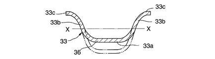
- FIG. 2 is a cross-sectional view taken along a plane perpendicular to the wheel radial direction of the spoke portion of the disk portion of the disk of the vehicle wheel according to the embodiment of the present invention (cross-sectional view taken along the line II in FIG. 2). It is. However, in order to compare the case where the wavy portion is not provided with the case where the wavy portion is provided, both are indicated by a two-dot chain line.
- the shape of the wavy portion is a shape in which only one wave of one cycle is provided. It is sectional drawing.
- the shape of the wavy portion is a shape in which only one half-cycle wave is provided. It is sectional drawing.
- the shape of the corrugated portion is a shape in which only one wave of one cycle is provided. It is sectional drawing.
- the shape of the wavy portion is a shape in which only one half-cycle wave is provided. It is sectional drawing.
- the disk of the vehicle wheel according to the embodiment of the present invention is a case where the wavy portion is provided on both the spoke bottom wall and the spoke reinforcing plate of the spoke portion, and the shape of the wavy portion is one cycle on the spoke bottom wall and the spoke reinforcing plate. It is a half sectional view in the case of having a shape in which one wave is provided. It is explanatory drawing of the shape of a wave. It is a fragmentary sectional view at the time of providing the step-shaped transition part between the decoration hole and the disk outer peripheral part of the wheel for motor vehicles of this invention Example. It is a fragmentary sectional view at the time of providing the step-shaped transition part between the decoration hole and the disk outer peripheral part of the wheel for motor vehicles of this invention Example.
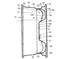
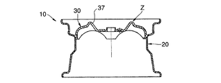
- an automobile wheel (hereinafter also simply referred to as a wheel) according to an embodiment of the present invention includes a rim 20 and a disk 30 manufactured from a plate material.
- the wheel 10 is made of steel, for example. However, the wheel 10 may not be made of steel, and may be made of aluminum alloy, titanium alloy, or the like as long as it has a disk 30 formed (for example, press-molded) from a plate material.
- the wheel 10 is a two-piece wheel in which the rim 20 and the disk 30 are manufactured separately and integrated by welding or using a joining member such as a rivet (not shown).
- the rim 20 includes an inner flange portion 21, an inner bead seat portion 22, an inner sidewall portion 23, a drop portion 24, an outer sidewall portion 25, an outer bead seat portion 26, an outer flange portion 27, Is provided.
- the inner flange portion 21, the inner bead seat portion 22, and the inner sidewall portion 23 are arranged in the wheel axial direction when the wheel 10 is mounted on the vehicle, rather than the outer sidewall portion 25, the outer bead seat portion 26, and the outer flange portion 27. Located near the inside of the vehicle.
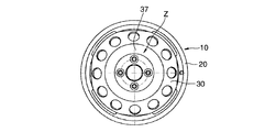
- the disk 30 has a hub hole 31, a hub mounting part 32, a spoke part 33, a disk outer peripheral part 34, a decorative hole 35, a corrugated part 36, and an inclined part 37.
- the disc 30 is an annular protrusion that is used in a general automobile wheel disc as shown in FIGS. 15 and 16 and that is continuous with the outer side in the disc radial direction of the inclined portion 37 in the circumferential direction and protrudes in the wheel axial direction. It does not have the part Z.
- the hub hole 31 is provided in the central portion in the wheel radial direction of the disk 30.
- the hub attachment portion 32 is provided around the hub hole 31.
- the hub attachment portion 32 has a flat plate shape or a substantially flat plate shape, and is in a plane orthogonal to or substantially orthogonal to the wheel axial direction (the axis of the disk 30).
- the hub mounting portion 32 is provided with a plurality of hub mounting bolt holes 32a. For example, five hub mounting bolt holes 32a are provided at equal intervals in the circumferential direction of the wheel. However, the number of hub mounting bolt holes 32a is not limited to five, but may be three, four, or six or more.
- the disk 30 (wheel 10) is fixed to the hub by inserting hub mounting bolts (both not shown) extending from the hub into the hub mounting bolt holes 32a and screwing hub nuts (not shown) into the hub mounting bolts.
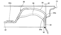
- the hub attachment portion 32 has a discontinuous annular shape that connects the hub attachment bolt holes 32a to each other in order to improve rigidity and durability of the hub attachment portion 32, and slightly ( An arch band 32b that bulges outward in the wheel axial direction and a bulge outwardly in the wheel axial direction (sub-rib 37a) that connects the inclined portion 37 and the hub mounting bolt hole 32a. It has been. As shown in FIG.
- the outer peripheral portion 32c of the hub mounting portion 32 (boundary portion with the inclined portion 37 of the hub mounting portion 32) has a circular shape except for the sub-ribs 37a. It does not enter the wheel radial direction inner side than the outermost diameter of the portion 32. However, as shown in FIG. 18, the connecting wall 38 enters the inner side in the wheel radial direction from the outermost diameter of the hub mounting portion 32, and the outer peripheral portion 32c of the hub mounting portion 32 does not form a circle in the portion other than the sub-rib 37a. May be. As shown in FIG. 2, the surface on the inner side in the wheel axial direction of the hub attachment portion 32 is between the outer side in the wheel axial direction and the inner side in the wheel axial direction of the disk outer peripheral portion 34 in the wheel axial direction.
- the spoke portion 33 extends radially from the inclined portion 37 to the outer periphery of the disk 34 in the wheel radial direction.
- a plurality of spoke portions 33 are provided.
- five spoke portions 33 are provided at equal intervals in the circumferential direction of the wheel.
- the number of spoke portions 33 is not limited to five, and may be three, four, or six or more as long as a plurality of spoke portions 33 are provided.
- the outer end of the spoke portion 33 in the radial direction of the wheel (the outer end of the disc in the radial direction) is folded back inward in the axial direction of the wheel to form the outer peripheral curved surface connecting portion R that connects to the outer peripheral portion 34. is doing.
- the inner end portion in the wheel radial direction (the inner end portion in the disk radial direction) of the spoke portion 33 forms an inner circumferential curved surface connection portion r that is folded back inward in the wheel axial direction and connected to the inclined portion 37.
- An intermediate portion in the wheel radial direction of the spoke portion 33 (between the outer peripheral curved surface connection portion R and the inner peripheral curved surface connection portion r in the wheel radial direction) is a direction orthogonal to the wheel axial direction (a direction substantially orthogonal to the wheel axial direction).
- the radial end portions of the spoke portion 33 in the wheel radial direction intermediate portion are substantially at the same position in the wheel axial direction.
- the spoke portion 33 Since the wheel radial direction intermediate portion of the spoke portion 33 extends in a direction perpendicular to the wheel axial direction, a large bending moment acts on the spoke portion 33 when a lateral load acts on the tire (rim 20) during vehicle travel. .
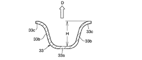
- the spoke portion 33 includes a spoke bottom wall 33a, a spoke side wall 33b, and spoke reinforcement, as shown in FIGS. A plate 33c.
- the spoke bottom wall 33a extends radially from the inclined portion 37 outward in the wheel radial direction.
- the spoke bottom wall 33a extends in the wheel circumferential direction (width direction of the spoke portion 33) in a cross-sectional view when cut along a plane orthogonal to the wheel radial direction.
- the spoke side wall 33b extends (rises) from both ends of the spoke bottom wall 33a in the wheel circumferential direction in a direction away from the spoke bottom wall 33a and in the wheel axial direction. As shown in FIG. 13, the spoke side wall 33b may extend outward from the spoke bottom wall 33a in the wheel axial direction, and may extend from the spoke bottom wall 33a inward in the wheel axial direction as shown in FIG. . In FIG. 13 and FIG. 14, D indicates the outer side in the wheel axial direction. In the embodiment of the present invention and the illustrated example, the case where the spoke side wall 33b extends outward from the spoke bottom wall 33a in the wheel axial direction will be described unless otherwise specified. As shown in FIGS.
- the spoke reinforcing plate 33 c is curved from the wheel axial direction end on the opposite side of the spoke bottom wall 33 a of the spoke side wall 33 b to the wheel circumferential direction from the wheel axial direction.
- the wheel extends in the wheel circumferential direction in the direction of increasing the wheel circumferential width.
- the spoke portion 33 is located on the outer side in the wheel axial direction from the hub mounting portion 32 and the disc outer peripheral portion 34. Therefore, when the wheel 10 is attached to the vehicle and the vehicle weight is applied, the grounded spoke portion 33 to which the load is applied is bent inward in the wheel axial direction. At this time, when the spoke side wall 33b extends outward from the spoke bottom wall 33a in the wheel axial direction, a tensile stress acts on the spoke reinforcing plate 33c in the wheel radial direction to support the load, so that it is easy to ensure rigidity. In addition, when the spoke side wall 33b extends from the spoke bottom wall 33a inward in the wheel axial direction, a compression stress acts on the spoke reinforcing plate 33c in the wheel radial direction. Less susceptible to cracks, improving durability.
- the wheel axial direction width H including the spoke reinforcing plate 33c of the spoke side wall 33b is in the vicinity of the inner end of the decorative hole 35 in the radial direction of the wheel as shown in FIG. The largest in the part.
- the maximum width of the wheel axial direction width H including the spoke reinforcing plate 33c of the spoke side wall 33b is in the range of 2 to 20 times the plate thickness of the spoke bottom wall 33a.
- it is desirable that the maximum width of the wheel axial direction width H including the spoke reinforcing plate 33c of the spoke side wall 33b is in a range of 4 to 10 times the plate thickness of the spoke bottom wall 33a. The reason is that the rigidity of the wheel 10 is high and the moldability of the disk 30 is also good.
- the wheel axial direction width H including the spoke reinforcing plate 33 c of the spoke side wall 33 b becomes narrower from the maximum portion toward the outer side in the wheel radial direction, but may be partially widened.
- a decorative window 35 is located between the spoke portions 33, 33 adjacent in the wheel circumferential direction.
- the width of the spoke portion 33 in the wheel circumferential direction is the narrowest at a portion corresponding to the wheel circumferential direction maximum inner diameter portion of the decorative window 35 on both sides of the wheel circumferential direction.
- the disc outer peripheral portion 34 is located at the outer end portion (including the vicinity thereof) in the wheel radial direction of the disc 30.
- the disk outer peripheral portion 34 has a ring shape, and connects the outer ends in the wheel radial direction of the plurality of spoke portions 33 in the wheel circumferential direction.
- the disk outer peripheral part 34 is cylindrical and has the same or substantially the same diameter over the entire length in the wheel axis direction.
- the disk outer peripheral portion 34 is fitted to the rim 20 at the drop portion 24 of the rim 20 and is fixed (joined) to the rim 20 by welding or the like.
- the fitting part with the rim 20 may be a part other than the drop part 24 such as the inner bead sheet part 22 or the outer bead sheet part 26.
- the disk outer peripheral portion 34 may be joined to the rim 20 only at the circumferential position W1 (see FIG. 1) on the inner side in the wheel axial direction adjacent to the decorative hole 35, and the wheel adjacent to the outer side in the wheel radial direction of the spoke portion 33. It may be joined to the rim 20 only at the axially inner circumferential position W2 (see FIG. 1), and is adjacent to the wheel axially inner circumferential direction between the decorative hole 35 and the spoke portion 33 outside the wheel radial direction. It may be joined to the rim 20 only at the position W3 (see FIG.
- any two positions (W1 and W2, W1 and W3, or W1 and W3, or circumferential positions W1, W2 and W3 inside the wheel axis direction) , W2 and W3) may be joined to the rim 20 or may be joined to the rim 20 at all the circumferential positions W1, W2, W3 on the inner side in the wheel axis direction.
- the disk outer peripheral part 34 is joined to the rim 20 by welding only at the circumferential position W1, it is welded at a position having a lower rigidity than the circumferential position W2, and the stress concentration in the welded part is alleviated, The fatigue durability of the wheel 10 is improved.
- the disk outer peripheral portion 34 When the disk outer peripheral portion 34 is joined to the rim 20 by welding only at the circumferential position W2, the force from the rim 20 is reliably transmitted to the hub mounting portion 32 through the spoke portion 33. Even when the disk outer circumferential portion 34 is joined to the rim 20 by welding only at the circumferential position W3, the circumferential position can be obtained even when the decorative hole 35 is formed prior to the press forming of the portion that becomes the disk outer circumferential portion 34. The position in the wheel axial direction after the press forming of W3 is stable, and welding can be reliably performed.
- the wheel axial direction position W of welding may be the wheel axial direction inner side of the disk outer peripheral portion 34 (see FIGS. 2, 11, and 12). It may be on the outer side (not shown) of the disk outer peripheral part 34 in the wheel axis direction, or may be both on the inner side in the wheel axis direction and on the outer side in the wheel axis direction of the disk outer peripheral part 34.
- the same number of decoration holes 35 as the number of spoke portions 33 are provided between adjacent spoke portions 33, 33 at equal intervals in the wheel circumferential direction.
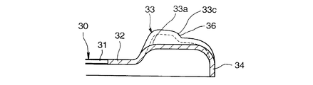
- the wheel radial direction outer end portion 35 a of the decoration hole 35 is the innermost in the disk axial direction of the decoration hole 35. 2 and 17, the wheel radial direction outer end portion 35 a of the decorative hole 35 reaches the disc outer peripheral portion 34 and is directly connected to the disc outer peripheral portion 34.
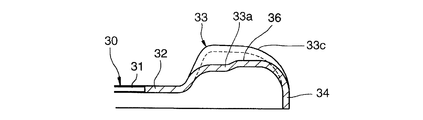
- the transition portion 34 a has a stepped shape, the diameter of the transition portion 34 a on the decorative hole 35 side is larger than the diameter on the disc outer peripheral portion 34 side, and the wheel radial outer end portion 35 a of the outer peripheral portion of the decorative hole 35 is formed.
- the outer circumferential surface of the disk 34 is located radially outward.
- the radius difference (stepped amount) d1 between the outer peripheral surface of the disk outer peripheral portion 34 and the outer peripheral surface of the transition portion 34a is the thickness of the disk outer peripheral portion 34 (for example, 5 mm, more generally 2.5 mm to 8 mm). It is desirable to be smaller. More preferably, the stepped amount d1 is 0.5 mm or more and less than the plate thickness of the disk outer peripheral portion 34.
- the stepped amount d1 is 0.5 mm or more and less than the plate thickness of the disk outer peripheral portion 34, the rigidity of the disk outer peripheral portion 34 is improved, and as a result, the durability of the wheel 10 is improved. Further, the stepped portion of the transition portion 34a facilitates positioning of the rim 20 and the disk 30 in the wheel axis direction when the rim 20 and the disk 30 are assembled. If the stepped amount d1 is smaller than 0.5 mm, the effect of positioning in the wheel axis direction is reduced. The stepped amount d1 may be larger than the plate thickness of the disk outer peripheral portion 34, but the moldability of the disk 30 deteriorates.
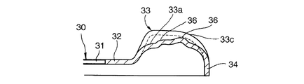
- the transition portion 34 a has a stepped shape, the diameter of the transition portion 34 a on the decorative hole 35 side is smaller than the diameter on the disk outer peripheral portion 34 side, and the outer peripheral portion of the outer peripheral portion of the decorative hole 35 in the wheel radial direction. 35 a is located radially inward from the outer peripheral surface of the disk outer peripheral portion 34.
- the difference in radius (stepped amount) d2 between the outer peripheral surface of the disk outer peripheral portion 34 and the outer peripheral surface of the transition portion 34a is the plate thickness (for example, 5 mm, more generally 2.5 mm to 8 mm) of the disk outer peripheral portion 34. It is desirable to be smaller.
- the stepped amount d2 is 0.5 mm or more and not more than the plate thickness of the disk outer peripheral portion 34.
- the stepped amount d2 is 0.5 mm or more and not more than the plate thickness of the disk outer peripheral portion 34, the rigidity of the disk outer peripheral portion 34 is improved, and as a result, the durability of the wheel 10 is improved.
- the diameter of the transition portion 34a is smaller than the diameter of the disc outer peripheral portion 34, the rim 20 and the disc 30 can be easily fitted together when the rim 20 and the disc 30 are assembled.
- the stepped amount d2 is smaller than 0.5 mm, the fitting between the rim 20 and the disc 30 is an interference fit, so that the disc 30 is deformed so that the stepped portion is reduced, so that the stepped effect is obtained. Less.
- the stepped amount d2 may be larger than the plate thickness of the disk outer peripheral portion 34, but the moldability of the disk 30 is deteriorated, and the decorative hole 35 is reduced to deteriorate the design.
- the wheel radial inner ends of the pair of spoke portions 33 located on both sides in the wheel circumferential direction of the decorative hole 35 are portions on the inner side in the wheel radial direction from the decorative hole 35, and the wheel circumferential cross-sectional shape.
- a flat (including substantially flat) connecting wall 38 By doing in this way, the stress concerning the connection wall 38 can be made small and durability of the disk 30 can be ensured. If the connecting wall 38 is flat in the vicinity of the boundary with the inclined portion 37, the stress at the boundary between the inclined portion 37 and the connecting wall 38 can be reduced, and the connecting wall 38 is separated from the inclined portion 37 outward in the wheel axis direction.
- the part may not be flat.
- the inclined portion 37 is a substantially cylindrical portion (conical frustum shape, tapered shape) on the outer periphery of the hub mounting portion 32.
- the inclined portion 37 connects the spoke bottom wall 33 a and the hub mounting portion 32.
- the inclined portion 37 extends from the outer peripheral portion 12c of the hub attachment portion 32 to the wheel radial direction outer side and the wheel axial direction outer side.
- the wavy portion 36 is compared with the case where the wavy portion 36 is not provided (two-dot chain line in FIG. 3).
- This is a part for reducing the section modulus around an axis (neutral axis) XX that is orthogonal to the wheel axis in the cross section when cut by a plane orthogonal to the wheel radial direction of the wheel and that is orthogonal to the wheel radial direction of each spoke portion 33. is there.
- the corrugated portion 36 reduces the bending rigidity around the axis XX perpendicular to the wheel axis of the spoke portion 33 and perpendicular to the wheel radial direction of each spoke portion 33. It is provided for.
- the wavy portion 36 is a portion in which a part of the spoke portion 33 has a wavy shape (wavy shape).
- the wavy portion 36 is provided on a part (not all) of the spoke portion 33 in the wheel radial direction.
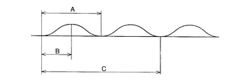
- the undulating portion 36 reduces the bending rigidity around the axis XX perpendicular to the wheel axis of the spoke portion 33 and perpendicular to the wheel radial direction of the spoke portion 33 while preventing the overall rigidity of the wheel 10 from being lowered. For this reason, the position of the minimum portion of the section modulus due to the wave shape is provided on the outer side in the wheel radial direction of the spoke portion 33 with respect to the wheel radial direction center.
- a part of the spoke bottom wall 33a of the spoke portion 33 in the wheel radial direction is part of the wheel radial direction. It may be provided only by being displaced outward (in a direction in which the rising amount of the pair of spoke side walls 33b is reduced and in a direction in which the length of the spoke portion 33 in the wheel axial direction is reduced). 7. As shown in FIG. 8, a part of the spoke reinforcing plate 33c of the spoke part 33 in the wheel radial direction is partly inward in the wheel axial direction (in a direction to reduce the rising amount of the pair of spoke side walls 33b).
- the waving portion 36 is a one-cycle wave as shown in FIG. 10A in a cross-sectional view taken along a plane orthogonal to the wheel circumferential direction of the spoke portion 33.
- FIG. 5 and FIG. 8 it is a shape in which only one half-cycle wave that is half of one cycle wave is provided as shown in FIG.
- FIG. 6 it may have a shape provided with a plurality of waves as shown in FIG.
- the corrugated portion 36 has a plurality of curved portions so as to be advantageous in fatigue strength and the like by suppressing local stress from being seen in a cross-sectional view when cut along a plane orthogonal to the wheel circumferential direction of the spoke portion 33. Or a plurality of curved portions and straight portions.
- the hub mounting bolt hole of the hub mounting portion is provided from the decorative hole peripheral curved portion that curves inward in the wheel axial direction inside the decorative hole in the wheel radial direction. No protrusions extending in the wheel radial direction from the wheel radial direction position to the inner side in the wheel radial direction are provided. Therefore, unlike the conventional wheel, the positional relationship and the number of the spoke portion and the hub mounting bolt hole are not restricted by the projection portion. However, if it is accepted that the positional relationship and the number of the spoke portions 33 and the hub mounting bolt holes 32a are restricted, the outermost diameter portion of the outer peripheral portion 32c of the hub mounting portion 32 as in the embodiment shown in FIG.
- a connecting wall 38 (rib, protrusion) is provided in which a portion of the connecting wall 38 that is located on the innermost side in the wheel radial direction (a portion of the connecting wall 38 that is located on the innermost side in the wheel axial direction) protrudes inwardly in the wheel radial direction. There is no problem. In the example of FIG. 18, the connecting wall 38 is directly connected to the hub mounting portion 32.
- a portion of the spoke portion 33 in the wheel radial direction is provided with a corrugated portion 36 that reduces the cross-sectional coefficient in the cross section when the spoke portion 33 is cut by a plane orthogonal to the wheel radial direction.
- the bending rigidity in the wheel radial direction of the portion of the spoke portion 33 where the wavy portion 36 is provided can be reduced. Therefore, even when the ribs (projections) provided in the past are eliminated, the stress concentrated on the end portion of the spoke portion 33 on the hub mounting portion 32 side can be distributed to the corrugated portion 36 as well.
- the corrugated portion 36 is provided in any one of the above (a), (b), and (c), the corrugated portion 36 having an effectively reduced section modulus is disposed on the spoke bottom wall 33a of the spoke portion 33 along the wheel axis direction. And / or the spoke reinforcing plate 33c of the spoke portion 33 can be provided by displacing in the wheel axial direction. Since the corrugated portion 36 is provided on the spoke bottom wall 33a, the rigidity of the spoke portion 33 in the disk circumferential direction is increased, and the surface rigidity of the wheel 10 is improved.
Landscapes
- Engineering & Computer Science (AREA)
- Mechanical Engineering (AREA)
- Rolling Contact Bearings (AREA)
- Tires In General (AREA)
Priority Applications (2)
| Application Number | Priority Date | Filing Date | Title |
|---|---|---|---|
| DE112009002642T DE112009002642T5 (de) | 2008-11-06 | 2009-11-05 | Fahrzeugrad |
| US13/099,402 US8491062B2 (en) | 2008-11-06 | 2011-05-03 | Vehicle wheel |
Applications Claiming Priority (4)
| Application Number | Priority Date | Filing Date | Title |
|---|---|---|---|
| JP2008285398 | 2008-11-06 | ||
| JP2008-285398 | 2008-11-06 | ||
| JP2009-253740 | 2009-11-05 | ||
| JP2009253740A JP5167226B2 (ja) | 2008-11-06 | 2009-11-05 | 自動車用ホイール |
Related Child Applications (1)
| Application Number | Title | Priority Date | Filing Date |
|---|---|---|---|
| US13/099,402 Continuation US8491062B2 (en) | 2008-11-06 | 2011-05-03 | Vehicle wheel |
Publications (1)
| Publication Number | Publication Date |
|---|---|
| WO2010053113A1 true WO2010053113A1 (ja) | 2010-05-14 |
Family
ID=42152921
Family Applications (1)
| Application Number | Title | Priority Date | Filing Date |
|---|---|---|---|
| PCT/JP2009/068890 Ceased WO2010053113A1 (ja) | 2008-11-06 | 2009-11-05 | 自動車用ホイール |
Country Status (4)
| Country | Link |
|---|---|
| US (1) | US8491062B2 (enExample) |
| JP (1) | JP5167226B2 (enExample) |
| DE (1) | DE112009002642T5 (enExample) |
| WO (1) | WO2010053113A1 (enExample) |
Cited By (1)
| Publication number | Priority date | Publication date | Assignee | Title |
|---|---|---|---|---|
| WO2012153577A1 (ja) * | 2011-05-09 | 2012-11-15 | トピー工業株式会社 | 車両用ホイールディスク |
Families Citing this family (8)
| Publication number | Priority date | Publication date | Assignee | Title |
|---|---|---|---|---|
| JP5548566B2 (ja) * | 2010-09-16 | 2014-07-16 | トピー工業株式会社 | 自動車用ホイールディスクの製造方法 |
| US9283805B2 (en) | 2011-02-07 | 2016-03-15 | Central Motor Wheel Co., Ltd. | Automobile wheel |
| DE102012107018B4 (de) * | 2012-08-01 | 2023-04-27 | Dr. Ing. H.C. F. Porsche Aktiengesellschaft | Fahrzeugfelge |
| JP2021194965A (ja) * | 2020-06-11 | 2021-12-27 | 中央精機株式会社 | 車両用ホイール、および、車両用ホイールの製造方法 |
| IT202200009545A1 (it) * | 2022-05-10 | 2023-11-10 | Mw Italia S R L | Ruota per veicoli con irrigidimenti in direzione circonferenziale |
| CN115891497A (zh) * | 2022-10-24 | 2023-04-04 | 滨州盟威戴卡轮毂有限公司 | 一种一体成型新能源铝车轮 |
| USD1037125S1 (en) | 2022-12-22 | 2024-07-30 | Moveero Inc. | Vehicle wheel |
| USD1037124S1 (en) | 2022-12-22 | 2024-07-30 | Moveero Inc. | Vehicle wheel |
Citations (7)
| Publication number | Priority date | Publication date | Assignee | Title |
|---|---|---|---|---|
| JPH10211801A (ja) * | 1997-01-30 | 1998-08-11 | Topy Ind Ltd | 不均板厚ディスク |
| JP2004536739A (ja) * | 2001-07-25 | 2004-12-09 | カール ウィールズ, リミテッド ライビリティ カンパニー | ホイール支持集成体とハブ |
| JP2005035330A (ja) * | 2003-07-16 | 2005-02-10 | Chuo Motor Wheel Co Ltd | 自動車用スチールホイールディスクの製造方法 |
| JP2005507334A (ja) * | 2001-10-30 | 2005-03-17 | ヘイズ・レマーズ・インターナショナル,インコーポレイテッド | 組立式車両ホイールおよびその製造方法 |
| JP2005509552A (ja) * | 2001-11-23 | 2005-04-14 | ソシエテ ド テクノロジー ミシュラン | 特に乗用車用のモータ車両ホイールディスク |
| JP2005511371A (ja) * | 2001-12-03 | 2005-04-28 | ソシエテ ド テクノロジー ミシュラン | 特に乗用車用のモータ車両ホイールディスク |
| JP2006347476A (ja) * | 2005-06-20 | 2006-12-28 | Bridgestone Corp | 車両用ホイール |
Family Cites Families (10)
| Publication number | Priority date | Publication date | Assignee | Title |
|---|---|---|---|---|
| US4610482A (en) * | 1985-03-07 | 1986-09-09 | Motor Wheel Corporation | Vehicle wheel with disc forming outer tire retaining flange |
| JP4702584B2 (ja) * | 2001-07-13 | 2011-06-15 | 株式会社アドヴィックス | 車両用ブレーキ液圧発生装置、及び該液圧発生装置を備えた液圧ブレーキ装置 |
| US6754957B2 (en) * | 2001-10-30 | 2004-06-29 | Hayes Lemmerz International, Inc. | Fabricated vehicle wheel and method for producing the same |
| US6629736B2 (en) * | 2001-10-30 | 2003-10-07 | Hayes Lemmerz International, Inc. | Fabricated vehicle wheel |
| US6655748B2 (en) * | 2001-10-30 | 2003-12-02 | Hayes Lemmerz International, Inc. | Fabricated vehicle wheel |
| US6626503B2 (en) * | 2001-10-30 | 2003-09-30 | Hayes Lemmerz International, Inc. | Fabricated vehicle wheel |
| JP2005507810A (ja) * | 2001-10-31 | 2005-03-24 | ヘイズ・レマーズ・インターナショナル,インコーポレイテッド | フルフェース組立式車両ホイール及びその製造方法 |
| US7464995B2 (en) | 2002-05-31 | 2008-12-16 | Hayes Lemmerz International, Inc. | Fabricated vehicle wheel having spokes and stiffening ribs |
| BRPI0508844B1 (pt) * | 2004-03-18 | 2018-01-30 | Hayes Lemmerz International, Inc. | Roda de veículo fabricada, disco de roda fabricado, método para produzir os mesmos |
| US7469973B2 (en) | 2005-03-04 | 2008-12-30 | Hayes Lemmerz International, Inc. | Fabricated vehicle wheel having a disc with a plurality of strengthening ribs |
-
2009
- 2009-11-05 WO PCT/JP2009/068890 patent/WO2010053113A1/ja not_active Ceased
- 2009-11-05 DE DE112009002642T patent/DE112009002642T5/de not_active Ceased
- 2009-11-05 JP JP2009253740A patent/JP5167226B2/ja active Active
-
2011
- 2011-05-03 US US13/099,402 patent/US8491062B2/en active Active
Patent Citations (7)
| Publication number | Priority date | Publication date | Assignee | Title |
|---|---|---|---|---|
| JPH10211801A (ja) * | 1997-01-30 | 1998-08-11 | Topy Ind Ltd | 不均板厚ディスク |
| JP2004536739A (ja) * | 2001-07-25 | 2004-12-09 | カール ウィールズ, リミテッド ライビリティ カンパニー | ホイール支持集成体とハブ |
| JP2005507334A (ja) * | 2001-10-30 | 2005-03-17 | ヘイズ・レマーズ・インターナショナル,インコーポレイテッド | 組立式車両ホイールおよびその製造方法 |
| JP2005509552A (ja) * | 2001-11-23 | 2005-04-14 | ソシエテ ド テクノロジー ミシュラン | 特に乗用車用のモータ車両ホイールディスク |
| JP2005511371A (ja) * | 2001-12-03 | 2005-04-28 | ソシエテ ド テクノロジー ミシュラン | 特に乗用車用のモータ車両ホイールディスク |
| JP2005035330A (ja) * | 2003-07-16 | 2005-02-10 | Chuo Motor Wheel Co Ltd | 自動車用スチールホイールディスクの製造方法 |
| JP2006347476A (ja) * | 2005-06-20 | 2006-12-28 | Bridgestone Corp | 車両用ホイール |
Cited By (5)
| Publication number | Priority date | Publication date | Assignee | Title |
|---|---|---|---|---|
| WO2012153577A1 (ja) * | 2011-05-09 | 2012-11-15 | トピー工業株式会社 | 車両用ホイールディスク |
| CN103492194A (zh) * | 2011-05-09 | 2014-01-01 | 都美工业株式会社 | 车辆用轮辐 |
| JPWO2012153577A1 (ja) * | 2011-05-09 | 2014-07-31 | トピー工業株式会社 | 車両用ホイールディスク |
| US9327547B2 (en) | 2011-05-09 | 2016-05-03 | Topy Kogyo Kabushiki Kaisha | Vehicle wheel disk |
| CN103492194B (zh) * | 2011-05-09 | 2016-08-17 | 都美工业株式会社 | 车辆用轮辐 |
Also Published As
| Publication number | Publication date |
|---|---|
| DE112009002642T5 (de) | 2013-04-04 |
| US8491062B2 (en) | 2013-07-23 |
| US20110210603A1 (en) | 2011-09-01 |
| JP5167226B2 (ja) | 2013-03-21 |
| JP2010132278A (ja) | 2010-06-17 |
Similar Documents
| Publication | Publication Date | Title |
|---|---|---|
| JP5394197B2 (ja) | 自動車用ホイールディスク | |
| JP5612339B2 (ja) | 自動車用ホイール | |
| JP5167226B2 (ja) | 自動車用ホイール | |
| JP4669064B2 (ja) | 自動車用ホイールディスク | |
| JP5057602B2 (ja) | 車両用ホイール | |
| US8454099B2 (en) | Wheel for vehicle | |
| JP5670316B2 (ja) | 自動車用ホイール | |
| CN102596589B (zh) | 汽车用轮辐 | |
| JP5770212B2 (ja) | 自動車用ホイール | |
| JP6125998B2 (ja) | 車両用ホイールディスク | |
| JP2010132277A5 (enExample) | ||
| US9139039B2 (en) | Automobile wheel | |
| JP5495808B2 (ja) | 自動車用ホイールディスク | |
| JP2012040947A (ja) | 車両用ホイール | |
| JP5592197B2 (ja) | 自動車用ホイール | |
| EP2327565B1 (en) | An improved semi full face steel wheel | |
| JP2009292322A (ja) | 自動車用ホイール | |
| US20050269865A1 (en) | Wheel and a wheel disc |
Legal Events
| Date | Code | Title | Description |
|---|---|---|---|
| 121 | Ep: the epo has been informed by wipo that ep was designated in this application |
Ref document number: 09824812 Country of ref document: EP Kind code of ref document: A1 |
|
| DPE2 | Request for preliminary examination filed before expiration of 19th month from priority date (pct application filed from 20040101) | ||
| WWE | Wipo information: entry into national phase |
Ref document number: 1120090026427 Country of ref document: DE |
|
| 122 | Ep: pct application non-entry in european phase |
Ref document number: 09824812 Country of ref document: EP Kind code of ref document: A1 |