WO2010052834A1 - ピラーガーニッシュの取付構造 - Google Patents
ピラーガーニッシュの取付構造 Download PDFInfo
- Publication number
- WO2010052834A1 WO2010052834A1 PCT/JP2009/005424 JP2009005424W WO2010052834A1 WO 2010052834 A1 WO2010052834 A1 WO 2010052834A1 JP 2009005424 W JP2009005424 W JP 2009005424W WO 2010052834 A1 WO2010052834 A1 WO 2010052834A1
- Authority
- WO
- WIPO (PCT)
- Prior art keywords
- garnish
- grip
- pillar
- vehicle
- opening
- Prior art date
- Legal status (The legal status is an assumption and is not a legal conclusion. Google has not performed a legal analysis and makes no representation as to the accuracy of the status listed.)
- Ceased
Links
Images


Classifications
-
- B—PERFORMING OPERATIONS; TRANSPORTING
- B60—VEHICLES IN GENERAL
- B60R—VEHICLES, VEHICLE FITTINGS, OR VEHICLE PARTS, NOT OTHERWISE PROVIDED FOR
- B60R13/00—Elements for body-finishing, identifying, or decorating; Arrangements or adaptations for advertising purposes
- B60R13/02—Internal Trim mouldings ; Internal Ledges; Wall liners for passenger compartments; Roof liners
- B60R13/0237—Side or rear panels
- B60R13/025—Pillars; Roof rails
-
- B—PERFORMING OPERATIONS; TRANSPORTING
- B60—VEHICLES IN GENERAL
- B60N—SEATS SPECIALLY ADAPTED FOR VEHICLES; VEHICLE PASSENGER ACCOMMODATION NOT OTHERWISE PROVIDED FOR
- B60N3/00—Arrangements or adaptations of other passenger fittings, not otherwise provided for
- B60N3/02—Arrangements or adaptations of other passenger fittings, not otherwise provided for of hand grips or straps
- B60N3/026—Arrangements or adaptations of other passenger fittings, not otherwise provided for of hand grips or straps characterised by the fixing means
-
- B—PERFORMING OPERATIONS; TRANSPORTING
- B60—VEHICLES IN GENERAL
- B60R—VEHICLES, VEHICLE FITTINGS, OR VEHICLE PARTS, NOT OTHERWISE PROVIDED FOR
- B60R13/00—Elements for body-finishing, identifying, or decorating; Arrangements or adaptations for advertising purposes
- B60R13/02—Internal Trim mouldings ; Internal Ledges; Wall liners for passenger compartments; Roof liners
- B60R13/0206—Arrangements of fasteners and clips specially adapted for attaching inner vehicle liners or mouldings
Definitions
- the present invention relates to a mounting structure of a pillar garnish provided so as to cover a passenger compartment side of a pillar of a vehicle body.
- a vehicle body pillar provided with a grip that can be gripped when getting on and off, for example, a center pillar provided with a grip for getting on and off the rear seat.
- a center pillar provided with a grip for getting on and off the rear seat.
- the gap between the grip and the garnish or the boundary between the garnish and the pillar may be conspicuous due to the influence of the alignment accuracy, and in that case, a separate cover member needs to be attached. For example, the number of parts increases.
- the vehicle body (1 ) Garnish (3) provided so as to cover the passenger compartment side of the pillar (2, 5a), and a grip (4) provided on the passenger compartment side of the pillar (2, 5a) so as to be gripped when getting on and off.
- the grip (4) is formed integrally with the garnish (3), and the garnish (3) fixes the garnish (3) to the pillar (2.5a).
- a fixing bracket portion (3a) provided integrally near the base of the vehicle and outside the vehicle, and an opening (3b) for enabling access to the fixing bracket portion (3a), and the garnish (3) It was assumed that the lid for closing the opening (3b) (10) are assembled.
- the grip (4) is formed in an arch shape protruding in one of the garnish (3) in the vehicle front-rear direction, and an edge (11) on the grip (4) side of the opening (3b), It should be in a position that does not overlap the grip (4) when viewed from the access direction, and the edge on the pillar (2, 5a) side of the lid (10) is attached to the pillar (2, 5a). It is good to be in the position covered with the trim body (12).
- the grip is integrally formed with the garnish provided on the pillar, it is not necessary to adjust the alignment between both members, and the fixing bracket portion is provided near the base of the grip in the garnish. Since it is provided, fixing strength of the grip is also secured by fixing the garnish to the pillar. Since the grip is integrally provided on the garnish, alignment between both members is not necessary, and the number of parts can be reduced. Since the fixing bracket is provided on the outside of the grip, the opening for fixing work, that is, the lid that closes the opening is hidden from the passenger compartment by the grip. Can be taken widely, and thereby the workability for fixing can be improved.
- the grip is formed in an arch shape that protrudes in one of the front and rear directions of the garnish, and the grip side edge of the opening is in a position that does not overlap with the grip when viewed from the front and rear direction of the vehicle.
- the drawing direction of the mold for forming the fixing bracket portion can be made coincident, and the manufacturing process of the garnish integrated with the grip can be simplified.
- the outer edge of the vehicle in the lid is in a position covered by the trim body attached to the pillar, the gap between the lid and the pillar is covered by the trim body, and the edge of the lid is not noticeable. It looks better.
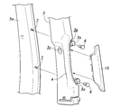
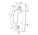
- FIG. 1 is a schematic overall view showing a car body of an automobile to which the present invention is applied. It is a disassembled perspective view which shows the garnish based on this invention. It is the principal part perspective view which looked at the garnish from the back side (vehicle body outer side). It is the front view which looked at the garnish from the front side (vehicle compartment side).
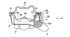
- FIG. 5 is a cross-sectional view taken along line VV in FIG.
- FIG. 1 is a schematic overall view showing a vehicle body 1 of an automobile to which the present invention is applied.
- FIG. 1 shows a portion of the center pillar 2 viewed from the vehicle interior side with a part broken away.
- the center pillar 2 of a four-door vehicle will be described, but the present invention can also be applied to other pillars.
- a garnish 3 made of a synthetic resin material is provided on the upper half side of the center pillar 2 on the vehicle interior side.
- the upper end portion of the garnish 3 is engaged with the decorative member on the ceiling side, and the lower end portion is engaged with the decorative member on the lower half side of the center pillar 2 so that the positional relationship between the garnish 3 and each member is maintained. It has become.
- the garnish 3 is integrally provided with an arch-shaped grip 4 that draws an arc along the center pillar 2 so as to be able to get on and off while gripping when getting on and off the rear seat.
- the grip 4 is formed integrally with the garnish 3 as described above, the positioning between the garnish 3 and the grip 4 is performed as in the case where the garnish 3 is made of a separate member and assembled separately to the pillar. There is no problem. In addition, the number of parts can be reduced.
- the garnish 3 has a pair of upper and lower tongue-shaped bracket portions 3a having bolt insertion holes for fixing to the inner panel 5a constituting the center pillar 2, and bolts 6 via the bracket portions 3a. And an opening 3b for performing an operation of screwing the inner panel 5a into the inner panel 5a.
- bolt 6 is provided in the side surface which faces the vehicle rear side of the inner panel 5a.
- each bracket portion 3 a is provided in the vicinity of a portion that becomes the base portion 4 a of the arch-shaped grip 4, and extends in a direction along the side surface of the inner panel 5 a with the garnish 3 attached.
- the garnish 3 can be applied even if a large load is applied to the grip 4. A large load is not transmitted to the other parts, and the garnish 3 is not deformed.
- a through anchor 8 through which a seat belt is passed is arranged on the surface of the garnish 3 facing the passenger compartment.
- the through anchor 8 is fixed by screwing a bolt 9b into a nut member 9a fixed to the back surface of the inner panel 5a at a predetermined position.
- the garnish 3 is formed with a bolt insertion hole 3c through which the bolt 9b is inserted. Since the garnish 3 is sandwiched between the bolt 9b fastened to the nut member 9a and the inner panel 5a, the garnish 3 is fixed to the inner panel 5a more firmly together with the screwing of the bracket portion 3a. It will be something.
- the opening 3b of the garnish 3 is closed by fitting a lid 10 made of a synthetic resin material as a separate member after the fixing operation with the bolt 6 is completed.
- the lid body 10 is provided with a plurality of engaging claws 10 a that can engage with the inner portion of the edge 11 of the opening 3 b.
- the bracket portion 3 a and the opening 3 b are provided on the vehicle outer side with respect to the grip 4.
- the garnish 3 is formed by resin molding as described above. As shown in FIG. 5, the garnish 3 protrudes toward the vehicle rear side, which is one of the vehicle front and rear directions, and the grip of the opening 3b. 4 side edge 11 exists in the position which does not overlap with the grip 4 seeing from the vehicle front-back direction (For example, the access direction from the vehicle rear shown by the arrow A of FIG. 5). Thereby, as shown by the arrow A with respect to the opening 3b in the assembly of the lid 10, the lid 10 can be fitted linearly without avoiding the grip 4, and the workability is good. Furthermore, the die-cutting direction of the die that forms the opening 3b and the die-cutting direction of the die that forms the grip 4 can be matched as the reverse direction of the arrow A in the figure, and the manufacturing process can be simplified.
- a frame having a known closed cross-sectional structure is formed by the inner panel 5a and the outer panel 5b, and a molding member 12 as a trim body is formed at the flange fitting portion of both the panels 5a and 5b. It is fitted and assembled.
- the molding member 12 can hide the flange-matching portions of both the panels 5a and 5b, but can also hide the gap between the edge of the garnish 3 and the inner panel 5a. Further, the outer side of the lid 10, that is, the edge on the inner panel 5 a side is in a position hidden by the molding member 12.
Landscapes
- Engineering & Computer Science (AREA)
- Mechanical Engineering (AREA)
- Transportation (AREA)
- Vehicle Interior And Exterior Ornaments, Soundproofing, And Insulation (AREA)
- Passenger Equipment (AREA)
Abstract
Description
2 センターピラー
3 ガーニッシュ
3b 開口部
3a ブラケット部(固定用ブラケット部)
4 グリップ
5a インナパネル(ピラー)
10 蓋体
10b 縁
11 縁
12 モール部材(トリム体)
Claims (3)
- 車体のピラーの車室側を覆うように設けられたガーニッシュと、乗降時に把持可能に前記ピラーの前記車室側に設けられたグリップとを有し、
前記ガーニッシュに前記グリップが一体成形され、
前記ガーニッシュが、前記ガーニッシュを前記ピラーに固定するべく前記グリップの基部近傍かつ車外側に一体に設けられた固定用ブラケット部と、前記固定用ブラケット部へのアクセスを可能にするための開口部とを有し、
前記ガーニッシュに、前記開口部を塞ぐ蓋体が組み付けられることを特徴とするピラーガーニッシュの取付構造。 - 前記グリップが、前記ガーニッシュの車両前後方向の一方に突出するアーチ状に形成され、
前記開口部の前記グリップ側となる縁が、前記アクセス方向から見て前記グリップと重ならない位置にあることを特徴とする請求項1に記載のピラーガーニッシュの取付構造。 - 前記蓋体における前記車外側の縁が、前記ピラーに取り付けられたトリム体により覆われる位置にあることを特徴とする請求項1に記載のピラーガーニッシュの取付構造。
Priority Applications (3)
| Application Number | Priority Date | Filing Date | Title |
|---|---|---|---|
| JP2010536645A JP5303569B2 (ja) | 2008-11-05 | 2009-10-16 | ピラーガーニッシュの取付構造 |
| CN200980141433.6A CN102186700B (zh) | 2008-11-05 | 2009-10-16 | 柱装饰件的安装构造 |
| US13/122,008 US8371632B2 (en) | 2008-11-05 | 2009-10-16 | Mounting structure for a pillar garnish |
Applications Claiming Priority (2)
| Application Number | Priority Date | Filing Date | Title |
|---|---|---|---|
| JP2008284771 | 2008-11-05 | ||
| JP2008-284771 | 2008-11-05 |
Publications (1)
| Publication Number | Publication Date |
|---|---|
| WO2010052834A1 true WO2010052834A1 (ja) | 2010-05-14 |
Family
ID=42152648
Family Applications (1)
| Application Number | Title | Priority Date | Filing Date |
|---|---|---|---|
| PCT/JP2009/005424 Ceased WO2010052834A1 (ja) | 2008-11-05 | 2009-10-16 | ピラーガーニッシュの取付構造 |
Country Status (4)
| Country | Link |
|---|---|
| US (1) | US8371632B2 (ja) |
| JP (1) | JP5303569B2 (ja) |
| CN (1) | CN102186700B (ja) |
| WO (1) | WO2010052834A1 (ja) |
Families Citing this family (7)
| Publication number | Priority date | Publication date | Assignee | Title |
|---|---|---|---|---|
| JP5327290B2 (ja) * | 2011-07-20 | 2013-10-30 | 株式会社ホンダアクセス | 車両用アシストグリップ |
| US8973941B2 (en) * | 2013-04-22 | 2015-03-10 | Nissan North America, Inc. | Vehicle interior trim panel |
| US9010841B1 (en) | 2013-12-03 | 2015-04-21 | Toyota Motor Engineering & Manufacturing North America, Inc. | Vehicle door trim panel assembly |
| US9925931B2 (en) | 2015-10-19 | 2018-03-27 | Ford Global Technologies, Llc | Reversible bracket for vehicle b-pillar trim |
| USD835555S1 (en) * | 2017-04-21 | 2018-12-11 | Jaguar Land Rover Limited | Front door casing |
| US11332082B1 (en) * | 2020-12-07 | 2022-05-17 | Ford Global Technologies, Llc | Vehicle trim panel assembly |
| US12024080B2 (en) | 2022-02-15 | 2024-07-02 | Toyota Motor Engineering & Manufacturing North America, Inc. | System for an assist pocket |
Citations (3)
| Publication number | Priority date | Publication date | Assignee | Title |
|---|---|---|---|---|
| JPS5732529U (ja) * | 1980-07-31 | 1982-02-20 | ||
| JPS6348642U (ja) * | 1986-09-19 | 1988-04-02 | ||
| JP2008155710A (ja) * | 2006-12-21 | 2008-07-10 | Toyota Auto Body Co Ltd | 乗降支援部を有する車両用内装部材及びそれを備えた車両 |
Family Cites Families (3)
| Publication number | Priority date | Publication date | Assignee | Title |
|---|---|---|---|---|
| US6037038A (en) * | 1998-03-30 | 2000-03-14 | Textron Automotive Company Inc. | Vehicle interior trim member having integrally molded hollow assist handle |
| JP3980315B2 (ja) | 2001-10-02 | 2007-09-26 | トヨタ車体株式会社 | アシストグリップの取付構造 |
| JP5023538B2 (ja) * | 2006-04-11 | 2012-09-12 | 日産自動車株式会社 | 自動車用室内トリム |
-
2009
- 2009-10-16 JP JP2010536645A patent/JP5303569B2/ja not_active Expired - Fee Related
- 2009-10-16 WO PCT/JP2009/005424 patent/WO2010052834A1/ja not_active Ceased
- 2009-10-16 CN CN200980141433.6A patent/CN102186700B/zh not_active Expired - Fee Related
- 2009-10-16 US US13/122,008 patent/US8371632B2/en not_active Expired - Fee Related
Patent Citations (3)
| Publication number | Priority date | Publication date | Assignee | Title |
|---|---|---|---|---|
| JPS5732529U (ja) * | 1980-07-31 | 1982-02-20 | ||
| JPS6348642U (ja) * | 1986-09-19 | 1988-04-02 | ||
| JP2008155710A (ja) * | 2006-12-21 | 2008-07-10 | Toyota Auto Body Co Ltd | 乗降支援部を有する車両用内装部材及びそれを備えた車両 |
Also Published As
| Publication number | Publication date |
|---|---|
| JPWO2010052834A1 (ja) | 2012-03-29 |
| US8371632B2 (en) | 2013-02-12 |
| CN102186700A (zh) | 2011-09-14 |
| JP5303569B2 (ja) | 2013-10-02 |
| US20110175386A1 (en) | 2011-07-21 |
| CN102186700B (zh) | 2014-06-25 |
Similar Documents
| Publication | Publication Date | Title |
|---|---|---|
| JP5303569B2 (ja) | ピラーガーニッシュの取付構造 | |
| US8408611B2 (en) | Vehicle door handle device | |
| US8443552B2 (en) | Mounting structure of door guard bar | |
| US7338076B2 (en) | Roll bar assembly and method for mounting the same | |
| EP2805876A1 (en) | Fender panel mounting structure for vehicle | |
| CN112140970B (zh) | 车厢结构 | |
| US20150368936A1 (en) | Distortion free door handle | |
| US8011709B2 (en) | Trim panel attachment assembly with anti-rotation flange | |
| US9649917B2 (en) | Vehicle resin back door structure | |
| KR101637303B1 (ko) | 자동차용 도어구조 | |
| CN106476573B (zh) | 用于固定车辆三角玻璃的结构 | |
| JP2013163441A (ja) | 車両用ドア | |
| US7234764B2 (en) | Mounting structure for sensor covered with step garnish | |
| CN110072721B (zh) | 车门构造 | |
| WO2016076012A1 (ja) | 車両のシートベルト取り付け部の補強構造 | |
| CN109383406B (zh) | 车门装饰件结构 | |
| JP2018512523A (ja) | 自動車ドア用ラッチ | |
| JP5313631B2 (ja) | 内装部材の取付構造 | |
| CN115071838B (zh) | 一种汽车尾门及汽车 | |
| JP2010023749A (ja) | 車両用インストルメントパネル上面部支持構造 | |
| JP4363913B2 (ja) | 自動車のドア構造 | |
| KR100897332B1 (ko) | 차량용 펜더 인슐레이터 | |
| JP5287141B2 (ja) | インサイドハンドルの取付構造 | |
| JP2010036682A (ja) | 車両用ドアインナハンドル装置の取付構造 | |
| JP6520522B2 (ja) | アーチモール取付構造 |
Legal Events
| Date | Code | Title | Description |
|---|---|---|---|
| WWE | Wipo information: entry into national phase |
Ref document number: 200980141433.6 Country of ref document: CN |
|
| 121 | Ep: the epo has been informed by wipo that ep was designated in this application |
Ref document number: 09824535 Country of ref document: EP Kind code of ref document: A1 |
|
| WWE | Wipo information: entry into national phase |
Ref document number: 2010536645 Country of ref document: JP |
|
| WWE | Wipo information: entry into national phase |
Ref document number: 13122008 Country of ref document: US |
|
| NENP | Non-entry into the national phase |
Ref country code: DE |
|
| 122 | Ep: pct application non-entry in european phase |
Ref document number: 09824535 Country of ref document: EP Kind code of ref document: A1 |