WO2010050481A1 - エンジン発電機 - Google Patents
エンジン発電機 Download PDFInfo
- Publication number
- WO2010050481A1 WO2010050481A1 PCT/JP2009/068432 JP2009068432W WO2010050481A1 WO 2010050481 A1 WO2010050481 A1 WO 2010050481A1 JP 2009068432 W JP2009068432 W JP 2009068432W WO 2010050481 A1 WO2010050481 A1 WO 2010050481A1
- Authority
- WO
- WIPO (PCT)
- Prior art keywords
- engine
- fuel
- housing
- air cleaner
- casing
- Prior art date
- Legal status (The legal status is an assumption and is not a legal conclusion. Google has not performed a legal analysis and makes no representation as to the accuracy of the status listed.)
- Ceased
Links
Images


Classifications
-
- F—MECHANICAL ENGINEERING; LIGHTING; HEATING; WEAPONS; BLASTING
- F02—COMBUSTION ENGINES; HOT-GAS OR COMBUSTION-PRODUCT ENGINE PLANTS
- F02B—INTERNAL-COMBUSTION PISTON ENGINES; COMBUSTION ENGINES IN GENERAL
- F02B63/00—Adaptations of engines for driving pumps, hand-held tools or electric generators; Portable combinations of engines with engine-driven devices
- F02B63/04—Adaptations of engines for driving pumps, hand-held tools or electric generators; Portable combinations of engines with engine-driven devices for electric generators
-
- F—MECHANICAL ENGINEERING; LIGHTING; HEATING; WEAPONS; BLASTING
- F02—COMBUSTION ENGINES; HOT-GAS OR COMBUSTION-PRODUCT ENGINE PLANTS
- F02B—INTERNAL-COMBUSTION PISTON ENGINES; COMBUSTION ENGINES IN GENERAL
- F02B63/00—Adaptations of engines for driving pumps, hand-held tools or electric generators; Portable combinations of engines with engine-driven devices
- F02B63/04—Adaptations of engines for driving pumps, hand-held tools or electric generators; Portable combinations of engines with engine-driven devices for electric generators
- F02B63/044—Adaptations of engines for driving pumps, hand-held tools or electric generators; Portable combinations of engines with engine-driven devices for electric generators the engine-generator unit being placed on a frame or in an housing
Definitions
- the present invention relates to the technology of an engine generator.
- an engine generator in which an engine, a generator, a control device, an air cleaner, and the like are provided in a housing is known.
- the air cleaner is disposed above the engine inside the housing, with its longitudinal direction being horizontal, i.e., sideways, and is fixed to the upper surface of the engine via a connecting member (for example, (See Patent Document 1).
- a maintenance space for replacing the element of the air cleaner is provided on the side of the air cleaner.
- the size of the housing can be reduced by making the air cleaner maintenance space as small as possible.
- the size of the casing is reduced at the expense of the maintenance space for the air cleaner as described above, the maintenance work for the air cleaner and thus the entire engine generator becomes difficult.
- an object of the present invention is to provide an engine generator capable of easily performing maintenance work of an air cleaner while reducing the size of a casing.
- an engine In the engine generator according to the present invention, an engine, a generator driven by the engine to generate power, an inverter that converts electric power generated by the generator into alternating current, and the engine and the power generator
- an engine generator comprising a control device for controlling the machine, an air cleaner for purifying air supplied to the engine, and a housing in which these members are provided
- the longitudinal direction of the air cleaner is vertical. As described above, it is arranged so as to face the exterior member of the control device on the upper side inside the casing, and a part of the facing side of the exterior member is recessed inside the control device. In this case, at least a part of the air cleaner is arranged in the part.
- fuel is supplied to the engine via a fuel pipe from an internal fuel tank provided inside the casing or an external fuel tank provided outside the casing.
- the fuel supply switching means is provided in the middle of the fuel pipe, and the fuel supply switching means allows the fuel supply source to the engine to be either the internal fuel tank or the external fuel tank. It is configured to be switchable.
- At least two channel-shaped fitting members that open downward are integrated into the bottom portion of the housing, and these fitting members are respectively extended in the lateral direction. They are arranged in parallel at a predetermined interval.
- a plurality of housing fixing holes are opened sideways in the fitting member.
- a maintenance space is formed below the air cleaner, and the maintenance work of the air cleaner can be performed from below. Therefore, maintenance work of the air cleaner can be easily performed.
- the engine generator according to the present invention it is possible to perform maintenance work of the air cleaner from the outside of the housing through the opening. Furthermore, the maintenance member through such an opening is not caught by the support member as compared with the support member having a corner. Therefore, maintenance work of the air cleaner can be easily performed.
- the engine generator it is possible to select either the fuel tank inside or outside the housing and supply the fuel to the engine. Therefore, the operating time of the engine generator can be arbitrarily extended by supplying fuel to the engine from an external fuel tank having a larger capacity than the internal fuel tank. Further, the fuel supply source to the engine can be easily switched using the fuel supply switching means.
- the fork of the forklift can be fitted to the fitting member. Therefore, the forklift can move the casing, and thus the entire engine generator. Further, it is possible to use the fitting member forming a part of the bottom of the housing as the fork hole without separately providing another member having a fork hole for fitting the fork of the forklift to the housing. . Therefore, it is possible to reduce the number of parts and reduce the cost.
- the hole formed in the fitting member forming a part of the bottom portion of the housing is used as the housing fixing means without separately providing other members in the housing. Is possible. Therefore, it is possible to reduce the number of parts and reduce the cost.
- other members are separately provided in the casing as means for fixing the casing and are fixed to the bottom of the casing by welding, there may be a problem that cracks occur when a load is applied to the welded portion. Trouble can be eliminated.
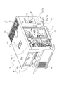
- FIG. 1 is a perspective view showing an external configuration of a casing in an engine generator
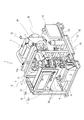
- FIG. 2 is a perspective view showing a configuration of the engine generator in a state where an opening / closing door of the casing is opened
- FIG. 3 is a casing in the engine generator.
- FIG. 4 is a perspective view showing an air cleaner mounting configuration
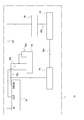
- FIG. 5 is a diagram explaining the configuration of the fuel system
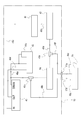
- FIG. 6 is a diagram explaining the configuration of another embodiment of the fuel system
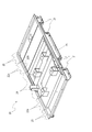
- FIG. 7 is a perspective view showing the configuration of the base of the housing.
- the engine generator 1 is an inverter type engine generator.
- the engine generator 1 includes a casing 10, a battery 2, an engine 3, a generator 4, an inverter 5, a cooling fan, a radiator 7, an air cleaner 8, an internal fuel tank 9a, and a muffler 50.
- the housing 10 is an exterior member of the engine generator 1, and each device such as the engine 3 and the generator 4 described above is provided inside the housing 10.
- the housing 10 includes a base 20 provided at the bottom and a cover 19 provided at the top.
- the battery 2 supplies power to a starter (not shown), a control unit of the inverter 5, a control panel 30 (to be described later), and the like when the engine 3 is started.
- the battery 2 is disposed in the front portion of the base 20 inside the housing 10.
- the engine 3 is a drive source for the engine generator 1.
- the engine 3 is disposed at a substantially central portion inside the housing 10 and is supported on the upper surface of the base 20 via a vibration isolation member (not shown).
- the generator 4 is driven by the power of the engine 3 to generate power.
- the generator 4 is disposed in front of the engine 3 and behind the battery 2.
- the inverter 5 rectifies the electric power generated by the generator 4 and then converts it into AC power having a predetermined frequency and outputs it.
- the inverter 5 is disposed in front of the engine 3 and is disposed on the right side of the casing 10, that is, in the vicinity of the front side of the right side surface of the cover 19.
- the cooling fan takes outside air into the housing 10.
- the cooling fan is disposed behind the engine 3 and in front of the radiator 7 and is driven by the power of the engine 3.
- the radiator 7 cools the cooling water that circulates in the engine 3.
- the radiator 7 is disposed behind the cooling fan and in the vicinity of the upper portion of the internal fuel tank 9a, and is connected to the engine via a communication pipe.
- the air cleaner 8 purifies outside air and supplies it to the engine 3.
- the air cleaner 8 is disposed behind the battery 2 inside the housing 10 and above the inside of the housing 10.
- the internal fuel tank 9 a is provided inside the housing 10 for supplying fuel to the engine 3.
- the internal fuel tank 9 a is disposed near the lower side of the radiator 7.
- the muffler 50 mutes the exhaust sound of the engine 3.
- the muffler 50 is disposed behind the radiator 7 and above the internal fuel tank 9a, and is connected to the engine 3 via an exhaust pipe.
- the tail pipe 3a extends upward to the ceiling portion of the casing 10, that is, near the upper plate 10e of the cover, and is opened so as to face the outside at the extended end portion. Then, the exhaust gas from the engine 3 can be discharged from the tail pipe 3a to the outside of the housing 10 via the exhaust pipe and the muffler 50.
- the control device controls the engine and generator.
- the control device is disposed in front of the generator 4 of the housing 10 and above the battery 2, and is disposed in the front side of the housing 10, that is, in the vicinity of the front plate 10 a of the cover 19.
- the control panel 30 performs operations such as starting the engine generator 1 and displays the operating state.
- the control panel 30 is disposed in front of the control device and is exposed to the outside at the upper part of the front side plate 10 a of the cover 19.
- each device is provided inside the housing 10. Then, fuel is supplied from the internal fuel tank 9a, air is supplied from the air cleaner 8, and the engine 3 is started.
- the generator 4 is driven by the power of the engine 3 to generate power.
- the electric power generated by the generator 4 is rectified by the inverter 5 and then converted into AC power having a predetermined frequency and output.
- the housing 10 is provided with the battery 2, the engine 3, and the like disposed above the base 20 inside the housing 10.
- the housing 10 is formed of a base 20 that forms the bottom and a cover 19 that forms the upper side.
- the cover 19 is configured such that the front side plate 10 a, the left side plate 10 b, the right side surface and the rear side surface are substantially perpendicular to the front, left and right and rear end portions of the base 20, respectively, and the upper plate 10 e is a box lid shape at the upper end portion of the housing 10. Configured.
- the upper frame 11 the cooling air inlet 14, the cooling air outlet 15, the oil supply port 16, the connection ports 17a and 17b, the control panel 30 and the like
- a control box 31 and the like are provided.
- the upper frame 11 has a horizontal direction between an upper end portion of the center beam 13 erected from the left side at the center portion in the front-rear direction of the base 20 and an upper end portion of the center frame 18 erected from the right side in the center portion in the front-rear direction of the base 20.
- the upper plate 10e is supported from below.
- the upper frame 11 is formed to be bent in a substantially U shape when viewed in cross section, and a locking tool 11a for lifting and moving the engine generator 1 is provided at a substantially central portion on the left and right sides. It can be locked to the stopper 11a and lifted.
- the cooling air inlet 14 serves as an inlet for taking outside air for cooling the battery 2, the engine 3, and the like into the housing 10 by driving the cooling fan.
- the cooling air inlet 14 is provided on the front side plate 10a from the substantially vertical center to the lower part.
- the cooling air outlet 15 serves as an outlet for exhausting outside air taken into the housing 10 from the cooling air inlet 14 to the outside of the housing 10 after cooling the battery 2, the engine 3, and the like. Further, the exhaust gas of the engine 3 discharged from the tail pipe 3 a is exhausted from the cooling air discharge port 15.
- the cooling air discharge port 15 is provided in a mesh shape at the rear portion of the upper plate 10e.
- the fuel filler port 16 communicates with the internal fuel tank 9a and supplies fuel from the fuel filler port 16.
- the fuel filler port 16 is covered with a fuel filler cap 16a.
- the oil filler port 16 is provided outside the left side plate 10 b and behind the opening 12.
- connection port 17a communicates an external fuel tank 9b provided outside the housing 10 and the housing 10 via a fuel pipe in order to supply fuel to the engine 3 from the outside of the housing 10.
- the connection port 17b allows the external fuel tank 9b and the housing 10 to communicate with each other via a fuel pipe in order to return the fuel supplied from the external fuel tank 9b and drained inside the housing 10 to the external fuel tank 9b. It is something to be made.
- the connection ports 17 a and 17 b are provided between the opening 12 and the fuel supply port 16 on the outside of the left side plate 10 b in the vicinity of the fuel supply port 16.
- a connection port cap 17c is detachably placed on each of the connection ports 17a and 17b.
- the control panel 30 performs operations such as starting the engine generator 1 and displays the operating state.
- the control panel 30 includes switches 30a and a monitor 30b.
- the control panel 30 is disposed at the upper part of the front plate 10 a and above the cooling air inlet 14.
- the switches 30a perform operations such as starting the engine generator 1, and are provided with a plurality of operation switches 34, 34,.
- the monitor 30b is for displaying an operation state or the like.
- the control box 31 is an exterior member that stores a control device (not shown) that controls the engine 3 and the generator 4.
- the control device is electrically connected to the operation switches 34, 34.
- the control box 31 is disposed at the rear side of the control panel 30 on the inner side of the housing 10 via the front side plate 10a.
- the control box 31 is provided on the outer peripheral portion of the control device in a substantially box shape by combining plate-like members.
- the air cleaner 8 is a structure that houses an element (not shown) in the main body of the air cleaner 8 and holds it with a lid 8a.
- the lid portion 8a can be removed, and the element can be removed from the air cleaner 8 main body and replaced by removing the lid portion 8a.
- the air cleaner 8 is arranged on the upper side inside the housing 10 so as to face the control box 31 that is an exterior member of the control device, with the longitudinal direction being the vertical direction.
- the air cleaner 8 is disposed in the recess 33 of the control box 31.
- the recess 33 is formed by a part of the control box 31 on the side facing the air cleaner 8 being recessed inward (side for housing each member of the control device).
- the concave portion 33 is formed by denting the corner (corner portion 31a) where the left side surface and the rear surface of the conventional control box 31 intersect.
- the engine generator 1 can be configured to include a left side plate 10b which is a side portion of the housing 10 and at least one opening 12 on the right side surface.
- the opening 12 is disposed on the left side plate 10b.
- the opening 12 is for an operator to perform internal maintenance work from outside the housing 10.
- the opening 12 is provided with an opening / closing door 12 a, and a center beam 13 is provided as a cylindrical support member facing the opening 12.
- the door 12a is a door that is opened when an operator performs maintenance work on the inside of the housing 10, and is configured to be openable and closable.
- the open / close door 12a is configured to cover the entire opening 12 with the open / close door 12a closed.
- the center beam 13 is configured to stand substantially vertically in order to increase the vertical rigidity of the opening 12.
- the center beam 13 is interposed between the base 20 which is the bottom of the casing 10 and the upper frame 10 which supports the ceiling of the casing 10, that is, the upper plate 10e of the cover 19, here the upper plate 19e. Established.
- the joint between the center beam 13 and the base 20 is disposed inside the housing 10 and in the vicinity of the opening 12.
- the air cleaner 8 can be attached to the upper side of the center beam 13. That is, the air cleaner 8 is connected and fixed via the center beam 13 and the fixing member 8b.
- the fixing member 8b is formed by bending a plate or the like, fixing one end of the front and rear to the upper portion of the center beam 13 by welding or the like, and attaching the air cleaner 8 to the other end of the front and rear.
- the maintenance work of the air cleaner 8 can be performed from the outside of the housing 10 through the opening 12. Further, during the maintenance work through the opening 12, the center beam 13, which is a cylindrical support member, is not caught as compared with the support member having a corner. Therefore, the maintenance work of the air cleaner 8 can be easily performed.
- the center beam 13 can be formed by a round pipe-like member.
- the upper end of the center beam 13, which is a round pipe-shaped member is opened in the recess of the upper frame 11, and the lower end is opened downward by the base 20.
- the rainwater that has entered the recesses of the upper frame 11 from the recesses 11b provided on the upper plate 10e of the cover 19 passes through the center beam 13 and flows downward to be discharged. In this way, it is possible to drain rain water without providing a gutter or the like and without polluting the side plate.
- the fuel path for supplying fuel from the internal fuel tank 9a to the engine 3 is mainly composed of the internal fuel tank 9a, the water separator 43, the feed pump 44, the fuel filter 45, and the fuel injection pump 46.
- the internal fuel tank 9a is provided inside the housing 10 for supplying fuel to the engine 3 as described above.
- the fuel in the internal fuel tank 9a is sent to the water separator 43 via a fuel supply hose 49a which is a fuel pipe for supplying fuel.
- the water separator 43 removes moisture contained in the fuel.
- the fuel sent to the water separator 43 is sent to the feed pump 44 through the fuel supply hose 49b.
- the feed pump 44 sucks fuel from the internal fuel tank 9a and supplies it to the engine 3.
- the fuel sent to the feed pump 44 is sent to the fuel filter 45 via the fuel supply hose 49c.
- the fuel filter 45 removes foreign matters in the fuel with a filter.
- the fuel sent to the fuel filter 45 is sent to a fuel injection pump 46 provided in the engine 3 through a fuel supply hose 49d.
- the fuel injection pump 46 pressurizes the fuel to a high pressure.
- the fuel pressurized to a high pressure is sent to the fuel injection nozzle 46a, injected into the cylinder, and burned.
- the external fuel tank 9b is a fuel tank provided outside the housing 10, and is capable of supplying fuel to the engine 3 via a fuel pipe.
- the external fuel tank 9b and the internal fuel tank 9a are configured so that the fuel supply source to the engine 3 can be switched to one of the fuel tanks by three-way cocks 40a and 40b as fuel supply switching means. .
- the external fuel tank 9b is provided with one end of a fuel supply hose 49e as a fuel pipe for supplying fuel and one end of a drain hose 48c as a fuel pipe for returning fuel.
- the other ends of the fuel supply hose 49e and the drain hose 48c are connected to a connection port 17a and a connection port 17b provided on the side surface of the housing 10, respectively.
- a three-way cock 40a and a three-way cock 40b serving as fuel supply switching means are respectively arranged in the middle of the fuel supply hose 49a and the drain hose 48a in the fuel pipe that connects the internal fuel tank 9a and the engine 3. Is done.
- the three-way cocks 40a and 40b switch the fuel path from the internal fuel tank 9a to the external fuel tank 9b.
- the operation of the three-way cocks 40a and 40b can be performed manually by an operator by opening the opening / closing door 12a of the opening 12 from the outside of the housing 10. Therefore, the three-way cocks 40 a and 40 b are arranged at positions where the operator can operate from the opening 12 of the housing 10.
- the three-way cocks 40a and 40b can be constituted by electromagnetic valves, and in this case, they can be switched electrically by an operation of a switch or the like.
- One end of the fuel supply hose 49f is connected to the three-way cock 40a, and the other end of the fuel supply hose 49f is connected to the connection port 17a.
- One end of the drain hose 48b is connected to the three-way cock 40b, and the other end of the drain hose 48b is connected to the connection port 17b.
- the fuel supplied to the engine 3 is the external fuel tank 9b, the fuel supply hose 49e, the connection port 17a, the fuel supply hose 49f, the three-way cock 40a, and the fuel supply hose 49a.
- Water separator 43 (hereinafter, the same as when the internal fuel tank 9a is used).
- the fuel drained from the engine 3 is the fuel injection pump 46, fuel injection nozzle 46a, drain hose 48a, three-way cock 40b, drain hose 48b, connection port 17b, drain hose 48c, external fuel.
- the tanks 9b are sent in this order.
- the operating time of the engine generator 1 can be arbitrarily extended by supplying fuel to the engine 3 from the external fuel tank 9b having a larger capacity than the internal fuel tank 9a. Further, the fuel supply source to the engine 3 can be easily switched using the three-way cocks 40a and 40b which are fuel supply switching means.
- the base 20 that is the bottom of the housing 10 integrally incorporates at least two channel-shaped fitting members that open downward into the base 20, and these fitting members extend in the lateral direction, that is, in the left-right direction, respectively.
- a configuration may be adopted in which they are arranged in parallel at a predetermined interval.
- channel members 22a and 22b having a U-shaped cross-sectional view are integrally incorporated in the base 20 as the fitting members. That is, the base 20 is mainly composed of channel members 22a and 22b, a front member 23, an intermediate member 24, a rear member 25, and frames 26L and 26R.
- the front member 23 is a front portion of the base 20
- the middle member 24 is a substantially central portion in the front and rear of the base 20
- the rear member 25 is a bottom portion of the base 20 constituting the rear portion of the base 20.
- the base 20 is arranged in the order of the front member 23, the channel member 22a, the middle member 24, the channel member 22b, and the rear member 25 from the front side of the base 20, and is interposed between the channel member 22a and the channel member 22b.
- a desired distance can be set between the channel member 22a and the channel member 22b.
- the channel members 22a and 22b are substantially U-shaped in a cross-sectional view, and are arranged with the opening facing downward.
- the channel members 22a and 22b, the front member 23, the middle member 24, and the rear member 25 are arranged in parallel in the left-right direction and are integrally configured by being coupled.
- the frames 26L and 26R are frame members that are arranged from the front end portion to the rear end portion of the base 20 at the left and right edge portions of the base 20, respectively.
- the side ends of the channel members 22a and 22b are fixed in the middle in the longitudinal direction of the frames 26L and 26R, respectively, and the forks of the forklift can be inserted from the side openings of the channel members 22a and 22b.
- the fork of the forklift can be fitted into the channel members 22a and 22b which are fitting members. Therefore, the forklift can move the casing 10, and thus the engine generator 1 as a whole. Further, a channel member 22a that is a fitting member that forms a part of the base 20 that is the bottom of the housing 10 without separately providing the housing 10 with another member having a fork hole for fitting the fork of the forklift. -22b can be used as a fork hole. Therefore, it is possible to reduce the number of parts and reduce the cost.
- a plurality of fixing holes 21, 21... Which are housing fixing holes can be horizontally opened in the channel members 22 a and 22 b which are fitting members.
- fixing holes 21, 21... are opened in the front-rear direction on the vertical surfaces of the left and right end portions of the channel members 22 a, 22 b constituting the base 20.
- the holes formed in the channel members 22a and 22b which are fitting members forming a part of the bottom portion of the casing 10, are provided for fixing the casing without separately providing other members to the casing 10. It can be used as a means. Therefore, it is possible to reduce the number of parts and reduce the cost.
- other members are separately provided in the casing 10 as means for fixing the casing and are fixed to the bottom of the casing 10 by welding, there may be a problem that cracks occur when a load is applied to the welded portion. Such problems can be eliminated.
- an engine generator 1 that includes a control device that performs control, an air cleaner 8 that purifies air supplied to the engine 3, and a housing 10 in which these members are provided
- the air cleaner 8 is moved up and down in the longitudinal direction. As a direction, it arrange
- the maintenance cleaner is disposed below the air cleaner 8. To form over scan, it is possible to perform maintenance work of the air cleaner 8 from below. Therefore, the maintenance work of the air cleaner 8 can be easily performed. Moreover, it is not necessary to take a maintenance space for the air cleaner 8 in the lateral direction inside the housing 10, and the housing 10 can be downsized.
- fuel can be supplied from the internal fuel tank 9a provided inside the housing 10 or the external fuel tank 9b provided outside the housing 10 to the engine 3 through the fuel pipe, and the fuel pipe is in the middle.
- Three-way cocks 40a and 40b are provided as fuel supply switching means in the section, and the fuel supply switching means can switch the fuel supply source to the engine 3 to either the internal fuel tank 9a or the external fuel tank 9b. Therefore, it is possible to supply fuel to the engine 3 by selecting one of the fuel tanks inside or outside the housing 10. Therefore, the operating time of the engine generator 1 can be arbitrarily extended by supplying fuel to the engine 3 from the external fuel tank 9b having a larger capacity than the internal fuel tank 9a. Further, the fuel supply source to the engine 3 can be easily switched using the three-way cocks 40a and 40b as fuel supply switching means.
- channel members 22a and 22b which are channel-shaped fitting members that open downward at the bottom of the housing 10, are integrally incorporated, and these channel members 22a and 22b are respectively laterally, that is, horizontally. Since they are extended and arranged in parallel at a predetermined interval, the fork of the forklift can be fitted to the fitting member. Therefore, the forklift can move the casing 10, and thus the engine generator 1 as a whole. Further, without providing another member having a fork hole for fitting a fork of a forklift to the housing 10, a fitting member that forms a part of the base 20 that is the bottom of the housing 10 is used as the fork hole. It becomes possible to do. Therefore, it is possible to reduce the number of parts and reduce the cost.
- the bottom portion of the housing 10 is not provided separately in the housing 10. It becomes possible to utilize the hole formed in the fitting member which makes a part of as a means for fixing the housing. Therefore, it is possible to reduce the number of parts and reduce the cost.
- other members are separately provided in the casing 10 as means for fixing the casing and are fixed to the bottom of the casing 10 by welding, there may be a problem that cracks occur when a load is applied to the welded portion. Such problems can be eliminated.
- the present invention is applicable to an engine generator.
Landscapes
- Engineering & Computer Science (AREA)
- Chemical & Material Sciences (AREA)
- Combustion & Propulsion (AREA)
- Mechanical Engineering (AREA)
- General Engineering & Computer Science (AREA)
- Motor Or Generator Frames (AREA)
Abstract
筐体の小型化を図りながら、エアクリーナのメンテナンス作業を容易に行うことができるエンジン発電機を提供すべく、エアクリーナ8をその長手方向を上下方向として、筐体10の内部の上側で前記制御装置の外装部材である制御ボックス31と対向するように配置するとともに、外装部材である制御ボックス31の対向側の一部が前記制御装置の内側に凹むように形成して、この凹んだ部分(凹部33)にエアクリーナ8の少なくとも一部を配置した。
Description
本発明は、エンジン発電機の技術に関する。
従来、エンジン、発電機、制御装置、エアクリーナ等を筐体に内部に設けたエンジン発電機は公知となっている。このようなエンジン発電機において、エアクリーナはその長手方向を水平方向、即ち横向きとして、筐体の内部でエンジンの上方に配置され、前記エンジンの上面に接続部材を介して固定されている(例えば、特許文献1参照。)。そして、前記エアクリーナのエレメントの交換を行うためのメンテナンス用スペースが、エアクリーナの横側方に設けられている。
特開2008-14164号公報
従来のようなエンジン発電機において、エアクリーナのメンテナンス用スペースをできるだけ小さくすれば、筐体の小型化を図ることができる。しかし、このようにエアクリーナのメンテナンス用スペースを犠牲にして、筐体の小型化を図った場合、エアクリーナ、ひいてはエンジン発電機全体のメンテナンス作業が困難となる。
そこで本発明は、筐体の小型化を図りながら、エアクリーナのメンテナンス作業を容易に行うことができるエンジン発電機を提供することを目的とする。
本発明の解決しようとする課題は以上の如くであり、次にこの課題を解決するための手段を説明する。
本発明に係るエンジン発電機においては、エンジンと、前記エンジンにより駆動されて発電を行う発電機と、前記発電機により発電された電力を交流に変換して出力するインバータと、前記エンジンと前記発電機の制御を行う制御装置と、前記エンジンに供給される空気を浄化処理するエアクリーナと、これらの部材を内部に設ける筐体とを備えたエンジン発電機において、前記エアクリーナをその長手方向を上下方向として、前記筐体の内部の上側で前記制御装置の外装部材と対向するように配置するとともに、前記外装部材の対向側の一部が前記制御装置の内側に凹むように形成して、この凹んだ部分に前記エアクリーナの少なくとも一部を配置したものである。
また、本発明に係るエンジン発電機においては、前記筐体の側部に、少なくとも一つの開口部と、この開口部を開閉可能な開閉扉と、この開口部に臨み当該筐体の底部と天井部との間に介設される円柱形状の支持部材とを備え、前記エアクリーナを前記支持部材の上側に取り付けたものである。
また、本発明に係るエンジン発電機においては、前記筐体の内部に設けられた内部燃料タンク、または前記筐体の外部に設けられた外部燃料タンクから燃料配管を介して前記エンジンへ燃料を供給可能とし、前記燃料配管の中途部に燃料供給切換手段を設けて、この燃料供給切換手段により、前記エンジンへの燃料の供給元を前記内部燃料タンクと、前記外部燃料タンクとのいずれか一方に切換可能に構成したものである。
また、本発明に係るエンジン発電機においては、前記筐体の底部に下向きに開口するチャンネル形状の嵌合部材を少なくとも二つ一体的に組み込み、これらの嵌合部材をそれぞれ横方向に延長して互いに所定間隔をとって平行に配置したものである。
また、本発明に係るエンジン発電機においては、前記嵌合部材に複数の筐体固定用孔を横向きに開口したものである。
本発明の効果として、以下に示すような効果を奏する。
本発明に係るエンジン発電機においては、エアクリーナの下方にそのメンテナンス用スペースを形成して、エアクリーナのメンテナンス作業を下方から行うことが可能となる。したがって、エアクリーナのメンテナンス作業を容易に行うことができる。しかも、筐体の内部でエアクリーナのメンテナンス用スペースを横方向にとる必要がなくなり、筐体の小型化を図ることができる。
また、本発明に係るエンジン発電機においては、エアクリーナのメンテナンス作業を筐体の外部から開口部を通じて行うことが可能となる。さらに、このような開口部を通じたメンテナンス作業時に、角部を有する支持部材に比べて、支持部材に引っかかることがなくなる。したがって、エアクリーナのメンテナンス作業を容易に行うことができる。
また、本発明に係るエンジン発電機においては、筐体の内部または外部の燃料タンクのいずれか一方を選択して、燃料をエンジンへ供給することが可能となる。したがって、内部燃料タンクに比べて容量の大きい外部燃料タンクから燃料をエンジンへ供給するなどして、エンジン発電機の運転時間を任意に延長することができる。また、エンジンへの燃料の供給元を燃料供給切換手段を用いて容易に切り換えることができる。
また、本発明に係るエンジン発電機においては、フォークリフトのフォークを嵌合部材に嵌合させることが可能となる。したがって、このフォークリフトにより筐体、ひいてはエンジン発電機全体を移動させることができる。また、フォークリフトのフォークを嵌合させるためのフォーク孔を有する他の部材を筐体に別途設けることなく、筐体の底部の一部をなす嵌合部材をフォーク孔として利用することが可能となる。したがって、部品点数を削減して、コストの低減化を図ることができる。
また、本発明に係るエンジン発電機においては、他の部材を筐体に別途設けることなく、筐体の底部の一部をなす嵌合部材に形成した孔を筐体固定用手段として利用することが可能となる。したがって、部品点数を削減して、コストの低減化を図ることができる。また、他の部材を筐体固定用手段として筐体に別途設けて当該筐体の底部に溶接により固定した場合、溶接部分に負荷がかかると亀裂が入る不具合が発生することあるが、このような不具合をなくすことができる。
1 エンジン発電機
3 エンジン
8 エアクリーナ
9a 内部燃料タンク
9b 外部燃料タンク
10 筐体
12 開口部
13 センタービーム
20 ベース
21 固定孔
30 コントロールパネル
33 凹部
40a 三方コック
40b 三方コック
3 エンジン
8 エアクリーナ
9a 内部燃料タンク
9b 外部燃料タンク
10 筐体
12 開口部
13 センタービーム
20 ベース
21 固定孔
30 コントロールパネル
33 凹部
40a 三方コック
40b 三方コック
次に、発明の実施の例を説明する。
図1はエンジン発電機における筐体の外部の構成を示す斜視図、図2はエンジン発電機における筐体の開閉扉を開けた状態の構成を示す斜視図、図3はエンジン発電機における筐体の内部の構成を示す斜視図、図4はエアクリーナの取付構成を示す斜視図、図5は燃料系統の構成を説明する図、図6は燃料系統の別実施例の構成を説明する図、図7は筐体のベースの構成を示す斜視図である。
図1はエンジン発電機における筐体の外部の構成を示す斜視図、図2はエンジン発電機における筐体の開閉扉を開けた状態の構成を示す斜視図、図3はエンジン発電機における筐体の内部の構成を示す斜視図、図4はエアクリーナの取付構成を示す斜視図、図5は燃料系統の構成を説明する図、図6は燃料系統の別実施例の構成を説明する図、図7は筐体のベースの構成を示す斜視図である。
以下では、図1、図2および図3を用いて本発明に係るエンジン発電機の実施の一例であるエンジン発電機1について説明する。
なお、図1に示す矢印Dの方向を前方向として、前後および左右方向を規定する。
なお、図1に示す矢印Dの方向を前方向として、前後および左右方向を規定する。
エンジン発電機1は、インバータ式エンジン発電機である。エンジン発電機1には、筐体10、バッテリ2、エンジン3、発電機4、インバータ5、冷却ファン、ラジエータ7、エアクリーナ8、内部燃料タンク9aおよびマフラー50が備えられる。
筐体10は、エンジン発電機1の外装部材であり、筐体10の内部に前述のエンジン3や発電機4等の各機器を設けるものである。筐体10は、底部に備えるベース20と、上部に備えるカバー19とで構成される。
バッテリ2は、エンジン3の始動時に図示せぬスタータ、インバータ5の制御部、後述するコントロールパネル30等に電力を供給するものである。バッテリ2は、筐体10の内部でベース20の前部に配置される。
エンジン3は、エンジン発電機1の駆動源となるものである。エンジン3は、筐体10の内部の略中央部に配置され、ベース20の上面上に図示せぬ防振部材を介して支持される。
発電機4は、エンジン3の動力によって駆動され、発電するものである。発電機4は、エンジン3の前方であって、バッテリ2の後方に配置される。
インバータ5は、発電機4により発電された電力を整流した後に、所定の周波数の交流電力に変換して出力するものである。インバータ5は、エンジン3の右前方に配置されるとともに、筐体10の右側部、即ちカバー19の右側面の前側近傍に配置される。
前記冷却ファンは、筐体10の内部に外気を取り込むものである。前記冷却ファンは、エンジン3の後方であって、ラジエータ7の前方に配置され、エンジン3の動力によって駆動される。
ラジエータ7は、エンジン3内を循環させる冷却水を冷却するものである。ラジエータ7は、前記冷却ファンの後方であって、内部燃料タンク9aの上方付近に配置され、連通管を介してエンジンと接続される。
エアクリーナ8は、外気を浄化してエンジン3に供給するものである。エアクリーナ8は、筐体10の内部でバッテリ2の後方であって、筐体10の内部の上方に配置される。
内部燃料タンク9aは、エンジン3に燃料を供給するために筐体10の内部に設けられるものである。内部燃料タンク9aは、ラジエータ7の下方付近に配置される。
マフラー50は、エンジン3の排気音を消音するものである。マフラー50は、ラジエータ7の後方であって、内部燃料タンク9aの上方に配置され、排気管を介してエンジン3と接続される。
マフラー50からはテールパイプ3aが筐体10の天井部、即ちカバーの上板10e付近までは上方へ向けて延出され、その延出端部で外部に臨むように開口される。そして、エンジン3からの排気ガスが、前記排気管を介してマフラー50を経由し、テールパイプ3aから筐体10の外部へ排出可能とされる。
制御装置はエンジンや発電機等の制御を行うものである。前記制御装置は筐体10の発電機4の前方であって、バッテリ2の上方に配置されるとともに、筐体10の前側部、即ちカバー19の前側板10a近傍に配置される。
コントロールパネル30は、エンジン発電機1の起動等の操作や運転状態等の表示を行うものである。コントロールパネル30は、前記制御装置の前方に配置され、カバー19の前側板10aの上部において外部に露出される。
このようにして、エンジン発電機1においては、各機器が筐体10の内部に設けられる。そして、内部燃料タンク9aから燃料が供給され、エアクリーナ8から空気が供給されて、エンジン3が始動される。エンジン3の動力により発電機4が駆動され、発電が行われる。発電機4により発電された電力が、インバータ5により整流された後、所定の周波数の交流電力に変換されて出力される。
次に、前述した筐体10についてさらに詳しく説明する。
筐体10は、筐体10の内部でベース20の上側にバッテリ2やエンジン3等を配置するものである。筐体10は、その底部を構成するベース20とその上側を構成するカバー19から形成される。カバー19は、前側板10a、左側板10b、右側面および後側面がそれぞれベース20の前、左右および後端部より略垂直に構成され、上板10eが筐体10の上端部で箱蓋状に構成される。
筐体10では、その内部にバッテリ2やエンジン3等が設けられるほかに、上部フレーム11、冷却風導入口14、冷却風排出口15、給油口16、連結口17a・17b、コントロールパネル30および制御ボックス31等が設けられる。
筐体10は、筐体10の内部でベース20の上側にバッテリ2やエンジン3等を配置するものである。筐体10は、その底部を構成するベース20とその上側を構成するカバー19から形成される。カバー19は、前側板10a、左側板10b、右側面および後側面がそれぞれベース20の前、左右および後端部より略垂直に構成され、上板10eが筐体10の上端部で箱蓋状に構成される。
筐体10では、その内部にバッテリ2やエンジン3等が設けられるほかに、上部フレーム11、冷却風導入口14、冷却風排出口15、給油口16、連結口17a・17b、コントロールパネル30および制御ボックス31等が設けられる。
上部フレーム11は、ベース20の前後方向中央部で左側から立設したセンタービーム13上端部と、ベース20の前後方向中央部で右側から立設したセンターフレーム18の上端部との間に左右方向に架設され、上板10eを下方から支持するものである。上部フレーム11は、断面視略U字状に折り曲げ形成され、左右略中央部にはエンジン発電機1を吊り上げて移動するための係止具11aが設けられ、移動する時にはクレーン等のフックを係止具11aに係止して持ち上げることができる。
冷却風導入口14は、バッテリ2やエンジン3等を冷却するための外気を前記冷却ファンの駆動により筐体10の内部へ取り込む入口となるものである。冷却風導入口14は、前側板10aに上下方向略中央部から下部に渡って設けられる。
冷却風排出口15は、冷却風導入口14から筐体10の内部に取り込んだ外気を、バッテリ2やエンジン3等を冷却した後に筐体10外部へ排気する出口となるものである。また、テールパイプ3aから排出されるエンジン3の排気ガスが冷却風排出口15から排気される。冷却風排出口15は、上板10eの後部に網目状に設けられる。
給油口16は、内部燃料タンク9aに連通され、前記給油口16から燃料を給油するものである。給油口16には、給油口キャップ16aが被せられる。給油口16は、左側板10bの外側であって、開口部12の後方に設けられる。
連結口17aは、筐体10外部からエンジン3に燃料を供給するために、筐体10外部に設けられる外部燃料タンク9bと筐体10とを燃料配管を介して連通させるものである。
連結口17bは、外部燃料タンク9bから供給され筐体10の内部でドレン等される燃料を前記外部燃料タンク9bに戻すために、外部燃料タンク9bと筐体10とを燃料配管を介して連通させるものである。
連結口17a・17bは、給油口16近傍の左側板10bの外側で、開口部12と給油口16との間に設けられる。連結口17a・17bには、それぞれ連結口キャップ17cが着脱可能に被せられる。
連結口17bは、外部燃料タンク9bから供給され筐体10の内部でドレン等される燃料を前記外部燃料タンク9bに戻すために、外部燃料タンク9bと筐体10とを燃料配管を介して連通させるものである。
連結口17a・17bは、給油口16近傍の左側板10bの外側で、開口部12と給油口16との間に設けられる。連結口17a・17bには、それぞれ連結口キャップ17cが着脱可能に被せられる。
コントロールパネル30は、エンジン発電機1の起動等の操作や運転状態等の表示を行うものである。コントロールパネル30は、スイッチ類30aやモニター30b等で構成される。コントロールパネル30は、前側板10aの上部であって、冷却風導入口14の上方に配置される。
スイッチ類30aは、エンジン発電機1の起動等の操作を行うものであり、たとえば複数の操作スイッチ34・34・・・が設けられる。モニター30bは、運転状態等を表示するためのものである。
スイッチ類30aは、エンジン発電機1の起動等の操作を行うものであり、たとえば複数の操作スイッチ34・34・・・が設けられる。モニター30bは、運転状態等を表示するためのものである。
制御ボックス31は、エンジン3と発電機4の制御を行う図示せぬ制御装置等を格納する外装部材である。前記制御装置は、操作スイッチ34・34・・・と電気的に接続される。制御ボックス31は、コントロールパネル30の後部に、前側板10aを介して筐体10の内部側に配置される。制御ボックス31は、板状の部材が組み合わさり略箱状に前記制御装置の外周部に備えられる。
次に図3および図4を用いて、エアクリーナ8の配置構成について詳しく説明する。
エアクリーナ8は、エアクリーナ8本体に図示せぬエレメントをその内部に収納し蓋部8aで抑える構造物である。蓋部8aは取り外し可能であり、蓋部8aを取り外すことで前記エレメントをエアクリーナ8本体から取り出して交換可能に構成される。
図2に示す如く、エアクリーナ8は、長手方向を上下方向として、筐体10の内部の上側で、前記制御装置の外装部材である制御ボックス31に対向するように配置される。
また、エアクリーナ8は、制御ボックス31の凹部33に配置される。
凹部33とは、制御ボックス31においてエアクリーナ8に対向する側の一部が内側(前記制御装置の各部材を収納する側)に凹むことにより形成されるものである。本実施例の制御ボックス31においては、従来制御ボックス31の左側面と後面とが交わる角(角部31a)を凹ますことで、凹部33が形成される。凹部33にエアクリーナ8の少なくとも一部を配置することで、エアクリーナ8および制御ボックス31の配置スペースをコンパクトにすることができる。
凹部33とは、制御ボックス31においてエアクリーナ8に対向する側の一部が内側(前記制御装置の各部材を収納する側)に凹むことにより形成されるものである。本実施例の制御ボックス31においては、従来制御ボックス31の左側面と後面とが交わる角(角部31a)を凹ますことで、凹部33が形成される。凹部33にエアクリーナ8の少なくとも一部を配置することで、エアクリーナ8および制御ボックス31の配置スペースをコンパクトにすることができる。
以上の如く構成することにより、エアクリーナ8の下方にそのメンテナンス用スペースを形成して、エアクリーナ8のメンテナンス作業を下方から行うことが可能となる。したがって、エアクリーナ8のメンテナンス作業を容易に行うことができる。しかも、筐体10の内部でエアクリーナ8のメンテナンス用スペースを横方向にとる必要がなくなり、筐体10の小型化を図ることができる。
また、エンジン発電機1は、筐体10の側部である左側板10bおよび前記右側面に少なくとも一つの開口部12を備える構成とすることができる。本実施例においては、左側板10bに開口部12が配置される。
開口部12は、作業者が筐体10外部から内部のメンテナンス作業を行うものである。開口部12には開閉扉12aが設けられ、開口部12を臨んで円柱形状の支持部材としてセンタービーム13が設けられる。
開閉扉12aは作業者が筐体10の内部をメンテナンス作業する際に開ける扉であり、開閉可能に構成される。開閉扉12aは、開閉扉12aを閉じた状態で開口部12の全部を覆うように構成される。
センタービーム13は、開口部12の上下方向の剛性を高めるために略垂直に立設して構成される。センタービーム13は、筐体10の底部であるベース20と、筐体10の天井部、即ちカバー19の上板10e、ここでは上板19eを下側から支持する上部フレーム11との間に介設される。センタービーム13とベース20との接合部は、筐体10内側であって、開口部12の近傍に配置される。
また、センタービーム13の上側に、エアクリーナ8を取り付けることができる。即ち、エアクリーナ8は、センタービーム13と固定部材8bを介して連結固定される。固定部材8bはプレート等を折り曲げて、前後一端をセンタービーム13の上部に溶接等により固設し、前後他端にエアクリーナ8を取り付けるのである。
以上の如く構成することにより、エアクリーナ8のメンテナンス作業を筐体10の外部から開口部12を通じて行うことが可能となる。さらに、このような開口部12を通じたメンテナンス作業時に、角部を有する支持部材に比べて、円柱形状の支持部材であるセンタービーム13に引っかかることがなくなる。したがって、エアクリーナ8のメンテナンス作業を容易に行うことができる。
また、センタービーム13は、丸パイプ状の部材で形成される構成とすることができる。本実施例において丸パイプ状の部材であるセンタービーム13の上端は上部フレーム11の凹部内で開口され、下端はベース20で下方に開口されている。こうして、カバー19の上板10eに備える凹部11bから上部フレーム11の凹部に入り溜まった雨水は、センタービーム13内を通り、下方に流れて排出される構成としている。こうして、竪樋等を設けることなく、また、側板を汚すことなく雨水を排水することができるのである。
次に図5を用いて、エンジン発電機1に係る燃料の経路を説明する。
内部燃料タンク9aからエンジン3に燃料を供給するための燃料の経路は、主として内部燃料タンク9a、ウォータセパレータ43、フィードポンプ44、燃料フィルタ45および燃料噴射ポンプ46から構成される。
内部燃料タンク9aは、前述の如くエンジン3に燃料を供給するために筐体10の内部に設けられるものである。内部燃料タンク9aの燃料は、燃料を供給する燃料配管である燃料供給ホース49aを介してウォータセパレータ43に送られる。
ウォータセパレータ43は、燃料に含まれる水分を取り除くものである。ウォータセパレータ43に送られた燃料は、燃料供給ホース49bを介してフィードポンプ44に送られる。
フィードポンプ44は、燃料を内部燃料タンク9aから吸入してエンジン3へ供給するものである。フィードポンプ44に送られた燃料は、燃料供給ホース49cを介して燃料フィルタ45に送られる。
燃料フィルタ45は、フィルタにより燃料中の異物を取り除くものである。燃料フィルタ45に送られた燃料は、燃料供給ホース49dを介してエンジン3に設けられる燃料噴射ポンプ46に送られる。
燃料噴射ポンプ46は、燃料を高圧に加圧するものである。高圧に加圧された燃料は、燃料噴射ノズル46aへ送油され、シリンダ内に噴射され、燃焼される。
次に、エンジン3から内部燃料タンク9aへ戻る燃料の経路を説明する。
エンジン3、即ちエンジン3に設けられる燃料噴射ポンプ46や燃料噴射ノズル46aで使用されなかった燃料、所謂、余剰燃料を、燃料を戻す燃料配管であるドレンホース48aを介して燃料フィルタ45または内部燃料タンク9aにドレンされる。
エンジン3、即ちエンジン3に設けられる燃料噴射ポンプ46や燃料噴射ノズル46aで使用されなかった燃料、所謂、余剰燃料を、燃料を戻す燃料配管であるドレンホース48aを介して燃料フィルタ45または内部燃料タンク9aにドレンされる。
次に図6を用いて、内部燃料タンク9aに替えて、外部燃料タンク9bを使用する場合の燃料の経路を説明する。
外部燃料タンク9bとは、筐体10外部に設けられる燃料用のタンクであって、燃料配管を介してエンジン3に燃料を供給可能とするものである。外部燃料タンク9bと内部燃料タンク9aとは、燃料供給切換手段としての三方コック40a・40bにてエンジン3への燃料の供給元をいずれか一方の燃料タンクに切換可能に構成されるものである。
外部燃料タンク9bは、燃料を供給する燃料配管として燃料供給ホース49eおよび燃料を戻す燃料配管としてドレンホース48cの一端がそれぞれ連通して設けられる。燃料供給ホース49eおよびドレンホース48cの他端は筐体10の側面に設けられる連結口17aおよび連結口17bにそれぞれ連結される。
本実施例においては、内部燃料タンク9aとエンジン3とを連通する燃料配管のうち、燃料供給ホース49aおよびドレンホース48aの中途部に燃料供給切換手段としての三方コック40aおよび三方コック40bがそれぞれ配置される。
三方コック40a・40bは、燃料の経路を内部燃料タンク9aから外部燃料タンク9bに切り換えるものである。三方コック40a・40bの操作は、筐体10外部から開口部12の開閉扉12aを開け、作業者の手動で行うことができる。したがって、三方コック40a・40bは、筐体10の開口部12から作業者が操作可能な位置に配置される。ただし、三方コック40a・40bは電磁弁で構成することも可能であり、この場合、スイッチ等の操作で電気的に切り換えることが可能である。
三方コック40aは燃料供給ホース49fの一端が連結され、燃料供給ホース49fの他端は連結口17aと連結される。三方コック40bはドレンホース48bの一端が連結され、ドレンホース48bの他端は連結口17bと連結される。
即ち、三方コック40aを外部供給側に切り換え操作すると、エンジン3に供給される燃料は、外部燃料タンク9b、燃料供給ホース49e、連結口17a、燃料供給ホース49f、三方コック40a、燃料供給ホース49a、ウォータセパレータ43・・・(以下、内部燃料タンク9aの使用時と同じ)、の順番で送られるものである。
また、三方コック40bを切り換え操作すると、エンジン3からドレンする燃料は、燃料噴射ポンプ46・燃料噴射ノズル46a、ドレンホース48a、三方コック40b、ドレンホース48b、連結口17b、ドレンホース48c、外部燃料タンク9b、の順番で送られるものである。
以上の如く構成することにより、筐体10の内部の内部燃料タンク9aまたは外部の外部燃料タンク9bのいずれか一方を選択して、燃料をエンジン3へ供給することが可能となる。したがって、内部燃料タンク9aに比べて容量の大きい外部燃料タンク9bから燃料をエンジン3へ供給するなどして、エンジン発電機1の運転時間を任意に延長することができる。また、エンジン3への燃料の供給元を燃料供給切換手段である三方コック40a・40bを用いて容易に切り換えることができる。
次に図7を用いて、筐体10の底部を構成するベース20について詳しく説明する。
筐体10の底部であるベース20は、ベース20に下向きに開口するチャンネル形状の嵌合部材を少なくとも二つ一体的に組み込み、これらの嵌合部材は、それぞれ横方向、即ち左右方向に延長して互いに所定間隔をとって平行に配置される構成とすることができる。
本実施例においては、前記嵌合部材として断面視コの字状のチャンネル部材22a・22bがベース20に一体的に組み込まれる。即ちベース20は、主としてチャンネル部材22a・22b、前部材23、中部材24、後部材25およびフレーム26L・26Rから構成される。前部材23はベース20の前部分、中部材24はベース20の前後略中央部分、後部材25はベース20の後部分を構成するそれぞれベース20の底部となるものである。
ベース20は、ベース20の前側から前部材23、チャンネル部材22a、中部材24、チャンネル部材22b、後部材25の順番で配置され、チャンネル部材22aとチャンネル部材22bとの間に介装される中部材24の前後方向の長さを変更することにより、チャンネル部材22aとチャンネル部材22bとの間を所望の間隔にすることができる。
チャンネル部材22a・22bは、断面視で略コの字状であり、開口部を下側に向けて配置される。チャンネル部材22a・22b、前部材23、中部材24および後部材25はそれぞれ左右方向に平行に配置され、結合されることで一体的に構成される。
フレーム26L・26Rは、それぞれベース20の左右縁部にて、ベース20の前端部から後端部に渡って配置される枠材である。フレーム26L・26Rは、それぞれ長手方向中途にてチャンネル部材22a・22bの側端部が固設され、チャンネル部材22a・22bの側部開口からフォークリフトのフォークを挿入可能に構成される。
以上の如く構成することにより、フォークリフトのフォークを嵌合部材であるチャンネル部材22a・22bに嵌合させることが可能となる。したがって、このフォークリフトにより筐体10、ひいてはエンジン発電機1全体を移動させることができる。また、フォークリフトのフォークを嵌合させるためのフォーク孔を有する他の部材を筐体10に別途設けることなく、筐体10の底部であるベース20の一部をなす嵌合部材であるチャンネル部材22a・22bをフォーク孔として利用することが可能となる。したがって、部品点数を削減して、コストの低減化を図ることができる。
また、嵌合部材であるチャンネル部材22a・22bに複数の筐体固定用孔である固定孔21・21・・・を横向きに開口した構成とすることができる。
本実施例においては、ベース20を構成するチャンネル部材22a・22bの左右両側端部の縦面に固定孔21・21・・・が前後方向に開口される。
以上の如く構成することにより、他の部材を筐体10に別途設けることなく、筐体10の底部の一部をなす嵌合部材であるチャンネル部材22a・22bに形成した孔を筐体固定用手段として利用することが可能となる。したがって、部品点数を削減して、コストの低減化を図ることができる。また、他の部材を筐体固定用手段として筐体10に別途設けて筐体10の底部に溶接により固定した場合、溶接部分に負荷がかかると亀裂が入る不具合が発生することあるが、このような不具合をなくすことができる。
以上のように、エンジン3と、エンジン3により駆動されて発電を行う発電機4と、発電機4により発電された電力を交流に変換して出力するインバータ5と、エンジン3と発電機4の制御を行う制御装置と、エンジン3に供給される空気を浄化処理するエアクリーナ8と、これらの部材を内部に設ける筐体10とを備えたエンジン発電機1において、エアクリーナ8をその長手方向を上下方向として、筐体10の内部の上側で前記制御装置の外装部材である制御ボックス31と対向するように配置するとともに、外装部材である制御ボックス31の対向側の一部が前記制御装置の内側に凹むように形成して、この凹んだ部分(凹部33)にエアクリーナ8の少なくとも一部を配置したので、エアクリーナ8の下方にそのメンテナンス用スペースを形成して、エアクリーナ8のメンテナンス作業を下方から行うことが可能となる。したがって、エアクリーナ8のメンテナンス作業を容易に行うことができる。しかも、筐体10の内部でエアクリーナ8のメンテナンス用スペースを横方向にとる必要がなくなり、筐体10の小型化を図ることができる。
また、筐体10の側部に、少なくとも一つの開口部12と、この開口部12を開閉可能な開閉扉12aと、この開口部12に臨み筐体10の底部と天井部との間に介設される円柱形状の支持部材であるセンタービーム13とを備え、エアクリーナ8を支持部材であるセンタービーム13の上側に取り付けたので、エアクリーナ8のメンテナンス作業を筐体10の外部から開口部12を通じて行うことが可能となる。さらに、このような開口部12を通じたメンテナンス作業時に、角部を有する支持部材に比べて、円柱形状の支持部材であるセンタービーム13に引っかかることがなくなる。したがって、エアクリーナ8のメンテナンス作業を容易に行うことができる。
また、筐体10の内部に設けられた内部燃料タンク9a、または筐体10の外部に設けられた外部燃料タンク9bから燃料配管を介してエンジン3へ燃料を供給可能とし、前記燃料配管の中途部に燃料供給切換手段として三方コック40a・40bを設けて、この燃料供給切換手段により、エンジン3への燃料の供給元を内部燃料タンク9aと、外部燃料タンク9bとのいずれか一方に切換可能に構成したので、筐体10の内部または外部の燃料タンクのいずれか一方を選択して、燃料をエンジン3へ供給することが可能となる。したがって、内部燃料タンク9aに比べて容量の大きい外部燃料タンク9bから燃料をエンジン3へ供給するなどして、エンジン発電機1の運転時間を任意に延長することができる。また、エンジン3への燃料の供給元を燃料供給切換手段として三方コック40a・40bを用いて容易に切り換えることができる。
また、筐体10の底部に下向きに開口するチャンネル形状の嵌合部材であるチャンネル部材22a・22bを少なくとも二つ一体的に組み込み、これらのチャンネル部材22a・22bをそれぞれ横方向、即ち左右方向に延長して互いに所定間隔をとって平行に配置したので、フォークリフトのフォークを嵌合部材に嵌合させることが可能となる。したがって、このフォークリフトにより筐体10、ひいてはエンジン発電機1全体を移動させることができる。また、フォークリフトのフォークを嵌合させるためのフォーク孔を有する他の部材を筐体10に別途設けることなく、筐体10の底部であるベース20の一部をなす嵌合部材をフォーク孔として利用することが可能となる。したがって、部品点数を削減して、コストの低減化を図ることができる。
また、嵌合部材であるチャンネル部材22a・22bに複数の筐体固定用孔である固定孔21を横向きに開口したので、他の部材を筐体10に別途設けることなく、筐体10の底部の一部をなす嵌合部材に形成した孔を筐体固定用手段として利用することが可能となる。したがって、部品点数を削減して、コストの低減化を図ることができる。また、他の部材を筐体固定用手段として筐体10に別途設けて筐体10の底部に溶接により固定した場合、溶接部分に負荷がかかると亀裂が入る不具合が発生することあるが、このような不具合をなくすことができる。
本発明は、エンジン発電機に利用可能である。
Claims (5)
- エンジンと、前記エンジンにより駆動されて発電を行う発電機と、前記発電機により発電された電力を交流に変換して出力するインバータと、前記エンジンと前記発電機の制御を行う制御装置と、前記エンジンに供給される空気を浄化処理するエアクリーナと、これらの部材を内部に設ける筐体とを備えたエンジン発電機において、
前記エアクリーナをその長手方向を上下方向として、前記筐体の内部の上側で前記制御装置の外装部材と対向するように配置するとともに、
前記外装部材の対向側の一部が前記制御装置の内側に凹むように形成して、この凹んだ部分に前記エアクリーナの少なくとも一部を配置したことを特徴とするエンジン発電機。 - 前記筐体の側部に、少なくとも一つの開口部と、この開口部を開閉可能な開閉扉と、この開口部に臨み当該筐体の底部と天井部との間に介設される円柱形状の支持部材とを備え、前記エアクリーナを前記支持部材の上側に取り付けたことを特徴とする、請求項1に記載のエンジン発電機。
- 前記筐体の内部に設けられた内部燃料タンク、または前記筐体の外部に設けられた外部燃料タンクから燃料配管を介して前記エンジンへ燃料を供給可能とし、前記燃料配管の中途部に燃料供給切換手段を設けて、この燃料供給切換手段により、前記エンジンへの燃料の供給元を前記内部燃料タンクと、前記外部燃料タンクとのいずれか一方に切換可能に構成したことを特徴とする、請求項1または請求項2に記載のエンジン発電機。
- 前記筐体の底部に下向きに開口するチャンネル形状の嵌合部材を少なくとも二つ一体的に組み込み、これらの嵌合部材をそれぞれ横方向に延長して互いに所定間隔をとって平行に配置したことを特徴とする、請求項1から請求項3のいずれか一項に記載のエンジン発電機。
- 前記嵌合部材に複数の筐体固定用孔を横向きに開口したことを特徴とする、請求項4に記載のエンジン発電機。
Applications Claiming Priority (2)
| Application Number | Priority Date | Filing Date | Title |
|---|---|---|---|
| JP2008277336A JP2010106698A (ja) | 2008-10-28 | 2008-10-28 | エンジン発電機 |
| JP2008-277336 | 2008-10-28 |
Publications (1)
| Publication Number | Publication Date |
|---|---|
| WO2010050481A1 true WO2010050481A1 (ja) | 2010-05-06 |
Family
ID=42128842
Family Applications (1)
| Application Number | Title | Priority Date | Filing Date |
|---|---|---|---|
| PCT/JP2009/068432 Ceased WO2010050481A1 (ja) | 2008-10-28 | 2009-10-27 | エンジン発電機 |
Country Status (2)
| Country | Link |
|---|---|
| JP (1) | JP2010106698A (ja) |
| WO (1) | WO2010050481A1 (ja) |
Cited By (3)
| Publication number | Priority date | Publication date | Assignee | Title |
|---|---|---|---|---|
| EP2458193A1 (en) * | 2010-11-19 | 2012-05-30 | Honda Motor Co., Ltd. | Cogeneration apparatus |
| CN104047712A (zh) * | 2013-03-14 | 2014-09-17 | 江苏普盛动力股份有限公司 | 单缸柴油机静音发电机组 |
| JP2015180820A (ja) * | 2015-05-11 | 2015-10-15 | 富士重工業株式会社 | 携帯型エンジン |
Families Citing this family (5)
| Publication number | Priority date | Publication date | Assignee | Title |
|---|---|---|---|---|
| CN102128082B (zh) * | 2011-01-26 | 2012-08-22 | 无锡开普机械有限公司 | 便于电子调速器散热的柴油数码发电机 |
| CN102052150B (zh) * | 2011-01-26 | 2012-08-22 | 无锡开普机械有限公司 | 易维护紧凑型柴油数码发电机 |
| CN102042082B (zh) * | 2011-01-26 | 2012-06-13 | 无锡开普机械有限公司 | 易冷却紧凑型柴油数码发电机 |
| US9551451B2 (en) | 2015-04-01 | 2017-01-24 | Electro-Motive Diesel, Inc. | Skid structure for a powertrain |
| JP2023551106A (ja) * | 2020-10-28 | 2023-12-07 | ハイブリッドジェネレーター アーペーエス | 電力を提供するためのモバイルハイブリッド発電機システム |
Citations (5)
| Publication number | Priority date | Publication date | Assignee | Title |
|---|---|---|---|---|
| JPS5984263U (ja) * | 1982-11-26 | 1984-06-07 | ヤンマーディーゼル株式会社 | エンジン作業機セツト |
| JPS6126582Y2 (ja) * | 1978-01-31 | 1986-08-09 | ||
| JPH04285397A (ja) * | 1991-03-14 | 1992-10-09 | Yanmar Diesel Engine Co Ltd | 防音型エンジン作業機 |
| JPH074864U (ja) * | 1993-06-10 | 1995-01-24 | 株式会社クボタ | 防音型エンジン |
| JP2003193861A (ja) * | 2001-12-26 | 2003-07-09 | Yanmar Co Ltd | 防音型発電装置 |
-
2008
- 2008-10-28 JP JP2008277336A patent/JP2010106698A/ja active Pending
-
2009
- 2009-10-27 WO PCT/JP2009/068432 patent/WO2010050481A1/ja not_active Ceased
Patent Citations (5)
| Publication number | Priority date | Publication date | Assignee | Title |
|---|---|---|---|---|
| JPS6126582Y2 (ja) * | 1978-01-31 | 1986-08-09 | ||
| JPS5984263U (ja) * | 1982-11-26 | 1984-06-07 | ヤンマーディーゼル株式会社 | エンジン作業機セツト |
| JPH04285397A (ja) * | 1991-03-14 | 1992-10-09 | Yanmar Diesel Engine Co Ltd | 防音型エンジン作業機 |
| JPH074864U (ja) * | 1993-06-10 | 1995-01-24 | 株式会社クボタ | 防音型エンジン |
| JP2003193861A (ja) * | 2001-12-26 | 2003-07-09 | Yanmar Co Ltd | 防音型発電装置 |
Cited By (4)
| Publication number | Priority date | Publication date | Assignee | Title |
|---|---|---|---|---|
| EP2458193A1 (en) * | 2010-11-19 | 2012-05-30 | Honda Motor Co., Ltd. | Cogeneration apparatus |
| US8674529B2 (en) | 2010-11-19 | 2014-03-18 | Honda Motor Co., Ltd | Cogeneration apparatus |
| CN104047712A (zh) * | 2013-03-14 | 2014-09-17 | 江苏普盛动力股份有限公司 | 单缸柴油机静音发电机组 |
| JP2015180820A (ja) * | 2015-05-11 | 2015-10-15 | 富士重工業株式会社 | 携帯型エンジン |
Also Published As
| Publication number | Publication date |
|---|---|
| JP2010106698A (ja) | 2010-05-13 |
Similar Documents
| Publication | Publication Date | Title |
|---|---|---|
| JP2010106698A (ja) | エンジン発電機 | |
| US12371877B2 (en) | Construction equipment | |
| EP1582635B1 (en) | Swiveling work machine | |
| US9103092B2 (en) | Hybrid construction machine | |
| US20120174566A1 (en) | Construction machine | |
| US20130078071A1 (en) | Electric construction machine | |
| EP1897843A2 (en) | Hybrid industrial vehicle | |
| JP2015206223A (ja) | 建設機械 | |
| WO2020054091A1 (ja) | 電動式建設機械 | |
| WO2012100633A1 (zh) | 易维护空气滤清器的紧凑型柴油数码发电机 | |
| JP5254821B2 (ja) | 旋回作業機 | |
| JP5867193B2 (ja) | 建設機械の上部旋回体 | |
| JP6080793B2 (ja) | パッケージ収納型エンジン発電機 | |
| JP5746804B2 (ja) | 電動式建設機械 | |
| CN111075797B (zh) | 液压总成 | |
| JP4253260B2 (ja) | バッテリ併用型エンジン駆動溶接機 | |
| JP2010095859A (ja) | 作業機械の電装ボックス | |
| JP3579297B2 (ja) | 旋回式建設機械 | |
| CN105814259B (zh) | 液压挖掘机 | |
| JP4918528B2 (ja) | エンジン駆動発電機 | |
| JP4226507B2 (ja) | 旋回作業機のカバー装置 | |
| US20250100060A1 (en) | Compressor-mounted engine generator/welder | |
| JP4266868B2 (ja) | 旋回作業機の旋回台構造 | |
| CN221762349U (zh) | 用于作业机械的模块化集成组件、回转平台总成及作业机械 | |
| JPH09221789A (ja) | 建設機械の上部旋回体 |
Legal Events
| Date | Code | Title | Description |
|---|---|---|---|
| 121 | Ep: the epo has been informed by wipo that ep was designated in this application |
Ref document number: 09823591 Country of ref document: EP Kind code of ref document: A1 |
|
| NENP | Non-entry into the national phase |
Ref country code: DE |
|
| 122 | Ep: pct application non-entry in european phase |
Ref document number: 09823591 Country of ref document: EP Kind code of ref document: A1 |