WO2010050285A1 - リニアモータおよびリニアモータを備えた携帯機器 - Google Patents
リニアモータおよびリニアモータを備えた携帯機器 Download PDFInfo
- Publication number
- WO2010050285A1 WO2010050285A1 PCT/JP2009/064106 JP2009064106W WO2010050285A1 WO 2010050285 A1 WO2010050285 A1 WO 2010050285A1 JP 2009064106 W JP2009064106 W JP 2009064106W WO 2010050285 A1 WO2010050285 A1 WO 2010050285A1
- Authority
- WO
- WIPO (PCT)
- Prior art keywords
- linear motor
- movable
- movable part
- pole surface
- spiral coil
- Prior art date
- Legal status (The legal status is an assumption and is not a legal conclusion. Google has not performed a legal analysis and makes no representation as to the accuracy of the status listed.)
- Ceased
Links
Images


Classifications
-
- H—ELECTRICITY
- H02—GENERATION; CONVERSION OR DISTRIBUTION OF ELECTRIC POWER
- H02K—DYNAMO-ELECTRIC MACHINES
- H02K33/00—Motors with reciprocating, oscillating or vibrating magnet, armature or coil system
- H02K33/16—Motors with reciprocating, oscillating or vibrating magnet, armature or coil system with polarised armatures moving in alternate directions by reversal or energisation of a single coil system
-
- H—ELECTRICITY
- H02—GENERATION; CONVERSION OR DISTRIBUTION OF ELECTRIC POWER
- H02K—DYNAMO-ELECTRIC MACHINES
- H02K3/00—Details of windings
- H02K3/04—Windings characterised by the conductor shape, form or construction, e.g. with bar conductors
- H02K3/26—Windings characterised by the conductor shape, form or construction, e.g. with bar conductors consisting of printed conductors
Definitions
- the present invention relates to a linear motor and a portable device including the linear motor.
- a vibration motor having a movable part that vibrates by electromagnetic force from a coil is known.
- Japanese Patent Application Laid-Open No. 2006-68688 discloses a vibration actuator (vibration motor) including a mover made of a disk-shaped magnet and a coil arranged so as to surround the mover.
- a vibration actuator vibration motor
- a coil having a large thickness is arranged in a vertical direction so as to surround a disk-shaped movable part, and a disk-shaped coil is driven by electromagnetic force from the coil.
- the movable part is configured to linearly move in the vertical direction (thickness direction of the movable part).
- Japanese Patent Laid-Open No. 2004-174309 discloses a vibration including a permanent magnet, a vibrator disposed so as to face the permanent magnet, and a movable coil connected to the vibrator and formed in a cylindrical shape.
- An apparatus is disclosed.
- the movable coil has a coil winding surface disposed in a direction orthogonal to a rod-shaped guide rail extending in the moving direction of the vibrator, and the guide rail includes It is comprised so that it may vibrate with a vibrator
- the vibration actuator disclosed in the above Japanese Patent Application Laid-Open No. 2006-68688 is configured such that a disk-shaped movable portion moves in the vertical direction (thickness direction of the movable portion) using a coil having a large thickness in the vertical direction. Therefore, there is a problem that it is difficult to reduce the thickness of the device.
- the winding surface of the cylindrical moving coil is arranged in a direction orthogonal to the moving direction of the moving coil (the direction along the guide rail). Become. For this reason, since the length in the height direction of the winding surface of the movable coil is increased, there is a problem that it is difficult to reduce the thickness of the device.
- the present invention has been made to solve the above-described problems, and one object of the present invention is to provide a linear motor that can be reduced in thickness.
- a linear motor includes a spiral coil, a first magnetic pole surface having a first polarity on a surface facing the spiral coil, and a first polarity.
- a portable device includes the linear motor according to the first aspect.
- the linear motor according to the first aspect of the present invention can be thinned by the above configuration.
- the portable device according to the second aspect of the present invention can be thinned by the above configuration.
- FIG. 10 is a plan view for explaining a modification of the first to fifth embodiments of the present invention.
- FIG. 10 is a plan view for explaining a modification of the first to fifth embodiments of the present invention.
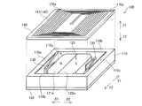
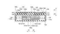
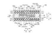
- a linear motor (linear drive vibration motor) 100 includes a frame 110 provided with a storage portion 110a and a movable member disposed in the storage portion 110a. A portion 120 and a pair of leaf springs 130 that support the movable portion 120 are provided.
- the frame 110 is an example of the “casing” in the present invention.
- the leaf spring 130 is an example of the “plate spring member” in the present invention.
- the frame body 110 is formed in a substantially rectangular shape (square shape) by a first side wall portion 110b extending in the directions of arrows X1 and X2 and a second side wall portion 110c extending in the directions of arrows Y1 and Y2 when viewed in plan. ing.
- the first side wall portion 110b is an example of the “inner side surface” in the present invention.
- the storage portion 110a of the frame body 110 includes a rectangular opening that penetrates in the vertical direction (arrow Z1 and Z2 directions).
- the printed circuit board 140 is disposed in the frame 110 so as to close the opening on the upper side (arrow Z1 direction side) of the storage portion 110a, and the opening on the lower side (arrow Z2 direction side).
- the bottom plate 150 is arranged so as to close the door.
- the frame 110, the printed circuit board 140, and the bottom plate 150 are made of glass epoxy resin.
- the movable portion 120 is formed in a rectangular shape (rectangular shape) whose corners are chamfered when viewed in a plan view, and a flat plate permanent magnet (a ferromagnetic material such as ferrite or neodymium). It is comprised by the magnet which consists of.
- the movable part 120 has a length of about 8 mm along the directions of the arrows X1 and X2, and has a length of about 10 mm along the directions of the arrows Y1 and Y2.
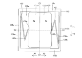
- the movable portion 120 is moved in the moving direction (arrow X1 (X2) direction) of the movable portion 120 by a pair of leaf springs 130 so as to be positioned substantially at the center of the storage portion 110a of the frame body 110 in a plan view. Sides are supported. Moreover, as shown in FIG. 3, the movable part 120 has a height (small thickness) lower than the height of the storage part 110a.
- the movable part 120 is composed of two permanent magnets including a first magnet 121 and a second magnet 122.
- the first magnet 121 is arranged on the arrow X1 direction side with the vicinity of the center line C1-C1 of the movable portion 120 (see FIG. 2) as a boundary
- the second magnet 122 is arranged on the arrow X2 direction side. It is comprised so that.
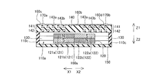
- an N pole surface 121a magnetized with N poles in the thickness direction is provided.
- an S pole surface 122a magnetized to the S pole in the thickness direction is provided on the side of the second magnet 122 facing the printed circuit board 140.
- the N pole and the S pole are examples of the “first polarity” and the “second polarity” of the present invention, respectively, and the N pole surface 121a and the S pole surface 122a are respectively “ It is an example of a “first magnetic pole surface” and a “second magnetic pole surface”.
- an S pole surface 121b magnetized to the S pole in the thickness direction is provided on the side facing the bottom plate 150 of the first magnet 121.
- an N pole surface 122b magnetized with N poles in the thickness direction is provided on the side of the second magnet 122 facing the bottom plate 150.
- the S pole surface 121b and the N pole surface 122b are examples of the “third magnetic pole surface” and the “fourth magnetic pole surface” in the present invention, respectively.
- the first magnet 121 and the second magnet 122 are adjacent to the N-pole surface 121a and the S-pole surface 122a on the surface on the printed circuit board 140 side, and on the surface on the bottom plate 150 side with the S-pole surface 121b and N It arrange
- the first magnet 121 and the second magnet 122 are in close contact with each other due to the attractive force between the N pole surface 121a and the S pole surface 122a adjacent to each other and the attractive force between the S pole surface 121b and the N pole surface 122b. And are fixed to each other by an adhesive or the like.
- the movable unit 120 linearly moves in the directions of the arrows X1 and X2 parallel to the printed circuit board 140 inside the storage unit 110a while being supported by the pair of leaf springs 130.
- the term “parallel” includes not only a state parallel to each other but also a state deviated from a parallel state (a state inclined at a predetermined angle) to the extent that the movable unit 120 does not hinder linear movement.
- the first side wall portion 110b (see FIG. 2) functions as a guide when the movable portion 120 moves in the directions of the arrows X1 and X2.
- each of the pair of leaf springs 130 is respectively disposed on the inner side surfaces of the second side wall portions 110c of the frame body 110, as shown in FIGS.
- each of the pair of leaf springs 130 includes a fixed portion 130 a fixed to the frame body 110, a bending portion 130 b, and a support portion 130 c of the movable portion 120.
- the fixing portion 130a is formed so as to extend along the directions of the arrows Y1 and Y2, and is fixed to the second side wall portion 110c of the frame 110 with an adhesive or the like.
- the bent portion 130b is bent a plurality of times (twice) between the boundary portion with the fixed portion 130a and the support portion 130c, so that the locus of the support portion 130c of the pair of leaf springs 130 is the center line C2-C2.
- the upper part is configured to bendable so as to move linearly along the directions of the arrows X1 and X2, and has a function of urging the movable part 120 toward the leaf spring 130 on the other side.
- the support portion 130c of each leaf spring 130 is configured to support the movable portion 120 so as to sandwich the movable portion 120 in the vicinity of the center line C2-C2 of the storage portion 110a of the frame portion 110.
- a yoke 160a made of an iron plate or the like is provided on the surface of the first magnet 121 and the second magnet 122 on the side facing the bottom plate 150.
- a yoke 160b made of an iron plate or the like is provided on the surface of the printed board 140 opposite to the side facing the movable portion 120.
- the yokes 160a and 160b have a function as a magnetic shield for suppressing magnetic leakage from the apparatus main body to the outside.
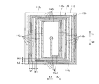
- planar coils 141 and 142 each having a two-layer wiring structure are arranged as shown in FIGS.
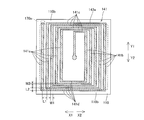
- Each of the planar coils 141 and 142 has a rectangular outline in plan view, and is formed by an XY plane (arrow X1 (X2) direction and arrow Y1 (Y2) direction) from the inside to the outside. It is formed in a spiral shape so as to spread in the (plane) direction.
- Each of the planar coils 141 and 142 is an example of the “coil” in the present invention.
- the planar coils 141 and 142 are electrically connected in series with each other by a single current line 143.
- the first layer current line 143a constituting the planar coil 141 is wound in a spiral shape counterclockwise from the outside to the inside.
- the outer end of the first layer current line 143 a of the planar coil 141 is connected to an electrode pad 170 a provided on the printed circuit board 140.
- the second layer current line 143b constituting the planar coil 142 is wound in a spiral shape counterclockwise from the inside to the outside.
- the outer end of the second layer current line 143 b of the planar coil 142 is connected to an electrode pad 170 b provided on the printed circuit board 140.
- the inner end portion of the first layer current line 143a constituting the planar coil 141 and the inner end portion of the second layer current line 143b constituting the planar coil 142 are printed in the vicinity of the respective central portions. They are connected to each other through contact holes provided in the substrate 140.
- the yoke 160b is provided with openings 160c and 160d at positions corresponding to the electrode pads 170a and 170b on the printed circuit board 140, respectively, and the yoke 160b and the electrode pads 170a and 170b are not in contact with each other.
- the planar coil 141 has first portions 141a and 141b extending in the directions of arrows Y1 and Y2, and second portions 141c and 141d extending in the directions of arrows X1 and X2, respectively.
- the width W2 of the current line 143a constituting the second portions 141c and 141d is formed to be smaller than the width W1 of the current line 143a constituting the first portions 141a and 141b of the planar coil 141.
- the pitch (distance between the centers of the adjacent current lines 143a) L2 of the current lines 143a constituting the second portions 141c and 141d is smaller than the pitch L1 of the current lines 143a constituting the first portions 141a and 141b.
- the magnitude of the magnetic flux generated by the current flowing in the first portions 141a and 141b is larger than the magnitude of the magnetic flux generated by the current flowing in the second portions 141c and 141d.
- the second portions 141c and 141d is disposed so as to overlap the first side wall portion 110b of the frame 110 when viewed in a plan view. That is, the arrangement area of the planar coil 141 is larger than the movable part 120 in plan view and covers the entire movable part 120.
- planar coil 142 has the same configuration as planar coil 141, and extends in the directions of arrows Y1 and Y2 and has a width W1, and extends in the directions of arrows X1 and X2.
- Second portions 142c and 142d having a width W2 are provided.
- a part of the second portions 142 c and 142 d is disposed so as to overlap the first side wall portion 110 b of the frame 110.
- the first portion 141a (142a) of the planar coil 141 (142) in a stationary state overlaps with the N pole surface 121a of the movable portion 120, and the first portion 141b (142b) is , And the S pole surface 122a.
- the current directions of the first portion 141a (142a) and the first portion 141b (142b) are opposite to each other.
- the electromagnetic force by the 1st part 141a (142a) and the 1st part 141b (142b) becomes a driving force for moving the movable part 120.
- a drive current is supplied to the current line 143 through the electrode pads 170a and 170b.
- an electric current flows into the 1st part 141a (142a) of the planar coil 141 (142) from the back side of a paper surface to this side.
- current flows from the front side to the back side of the first portion 141b (142b) of the planar coil 141 (142).
- the direction of the magnetic field generated between the N-pole surface 121a and the S-pole surface 122a of the movable part 120 is such that the N-pole surface 121a has an N-pole surface 121a on the N-pole surface 121a.
- the direction from the surface toward the printed circuit board 140 is the Z1 direction.
- the direction from the printed circuit board 140 toward the S pole surface 122a is the Z2 direction.
- the direction of the magnetic field generated between the N-pole surface 121a and the S-pole surface 122a of the movable portion 120 is determined by the first portion 141a (142a) and the first portion 141b (142b) of the planar coil 141 (142). This is perpendicular to the current flow direction.
- the current flowing through the first portion 141a (142a) of the planar coil 141 (142) receives a force in the direction of the arrow X1 from the magnetic field of the N pole surface 121a of the first magnet 121.
- the current flowing through the first portion 141b (142b) of the planar coil 141 (142) receives a force in the direction of the arrow X1 from the magnetic field of the S pole surface 122a of the second magnet 122.
- the first portion 141a (142a) of the planar coil 141 (142) and the first portion 141b (142b) of the planar coil 141 (142) are fixed to the printed circuit board 140, the movable portion 120 is caused by reaction. It is linearly moved in the direction of arrow X2.
- the movable portion 120 is linearly moved in the direction of the arrow X1 by the same operation as described above. .
- the movable unit 120 is linearly moved alternately in the direction of the arrow X1 and the direction of the arrow X2 so as to resonate.
- the magnetic flux generated between the S pole surface 121b of the first magnet 121 and the N pole surface 122b of the second magnet 122 is absorbed by the yoke 160a and selectively passes through the yoke 160a. It does not occur to penetrate to the outside.
- the magnetic flux generated between the N-pole surface 121a of the first magnet 121 and the S-pole surface 122a of the second magnet 122 is absorbed by the yoke 160b when passing through the printed circuit board 140 and is selectively passed through the yoke 160b. Does not extend to the outside of the yoke 160b.
- the movable portion 120 is moved along the directions of the arrows Y1 and Y2, respectively, by the electromagnetic force generated from the second portions 141c (142c) and 141d (142d) facing each other in the planar coil 141 (142). A force in a direction toward the center or a force in a direction of pulling outward from the center along the directions of the arrows Y1 and Y2 is applied.
- a movable portion 120 is provided that is movable along the direction along the surfaces of the planar coils 141 and 142 (arrow X1 and X2 directions). Accordingly, it is necessary to provide a moving range (moving space in the vertical direction) of the movable part 120 as compared with the case where the movable part 120 is linearly moved in the vertical direction using a coil having a large thickness in the vertical direction (Z direction). Therefore, the degree of freedom of design for reducing the thickness in that direction can be ensured. As a result, the linear motor 100 that can be thinned can be provided.
- planar coils 141 and 142 were spirally formed so as to be flat (flat surface) along the moving direction of the movable portion 120. This eliminates the need to provide a region in the height direction (height direction) due to the coil winding surface, compared to the case where the coil winding surface is arranged in a direction perpendicular to the moving direction of the movable part.
- the thickness in the directions of arrows Z1 and Z2 can be reduced. Therefore, the linear motor 100 can be thinned.
- the planar coil 141 (142) is disposed on one side of the movable portion 120 in the thickness direction. Thereby, compared with the case where the planar coil 141 (142) is arrange
- a movable portion (permanent magnet) 120 including a north pole surface 121a and a south pole surface 122a having different polarities is provided on the surface facing the planar coil 141 (142), and the north pole surface 121a and the south pole surface 122a.
- the first portions 141a and 141b (142a and 142b) of the planar coil 141 (142) in which the directions of current flow are opposite to each other are arranged at positions corresponding to the above.
- the N pole surface 121a and the S pole surface 122a of the movable part (permanent magnet) 120 are arranged so as to face the surface of the planar coil 141 (142).
- the magnetic force line (magnetic pole surface where the magnetic force line is generated) generated from the movable part 120 side and the magnetic flux line (coil surface where the magnetic flux line is generated) generated by passing a current through the planar coil 141 (142) become parallel.
- the magnetic force lines from the magnet and the magnetic flux lines from the coil are orthogonal to each other. Therefore, compared to the configuration described in the above Japanese Patent Application Laid-Open No. 2004-174309, the configuration in the linear motor 100 has a large amount of overlapping of the magnetic field lines and the magnetic flux lines, so that the driving force when moving the movable part 120 is correspondingly increased. Can be bigger.
- the S pole surface 121b is provided at a position corresponding to the N pole surface 121a and the position corresponding to the S pole surface 122a.
- N pole surface 122b was provided.
- the N pole surface 121a, the S pole surface 122a, the S pole surface 121b, and the N pole surface 122b of the movable portion 120 are mutually moved in the moving direction (arrow X1 and X2 directions) and the thickness direction (arrow Z1 and Z2 directions) are arranged so that different magnetic poles are adjacent to each other.
- the length of the magnetic flux generated between the magnetic pole surfaces is reduced, and accordingly, the leakage of the magnetic flux to the outside of the linear motor 100 can be suppressed.
- the linear motor 100 is disposed in various devices, it is possible to suppress the occurrence of device malfunction due to magnetic flux leakage from the linear motor 100.
- the magnetic flux generated between the S pole surface 121b and the N pole surface 122b is linear motor. It is possible to reliably suppress leakage from the bottom plate 150 side of 100 to the outside. Further, by arranging the yoke 160b on the surface of the printed circuit board 140, a magnetic flux is generated between the N-pole surface 121a and the S-pole surface 122a so as to pass through the yoke 160b while passing through the planar coils 141 and 142. To do.
- the movable part 120 By making the movable part 120 a rectangular shape with chamfered corners, it is caught between the first side wall part 110b of the frame part 110 when the movable part 120 moves compared to the case where the chamfered part is not chamfered. Can be suppressed. Therefore, it can suppress more reliably that the movable part 120 rotates resulting from such catch.
- the pitch L2 of the current lines 143a (143b) adjacent to the second portions 141c, 141d (142c, 142d) is equal to the pitch L1 of the current lines 143a (143b) adjacent to the first portions 141a, 141b (142a, 142b). It comprised so that it might become smaller.
- the current lines 143a (143b) adjacent to the second parts 141c, 141d (142c, 142d) are reduced by reducing the width W2 of the current lines 143a (143b) of the second parts 141c, 141d (142c, 142d).
- the pitch L2 between them is configured to be smaller than the pitch L1 between the adjacent current lines 143a (143b) of the first portions 141a, 141b (142a, 142b).
- the resistance of the current line 143a (143b) can be reduced by the increase in the width W1 of the current line 143a (143b) of the first portions 141a, 141b (142a, 142b), so the current line 143a (143b)
- the amount of current flowing through can be increased.
- the driving force of the movable part 120 can be increased.
- the second portions 141c (142c) and 141d (142d) of the planar coil 141 (142) are arranged so as to overlap the first side wall portion 110b when viewed in plan.
- the area where the forces in the directions of the arrows Y1 and Y2 act on the movable portion 120 can be reduced, so that when the movable portion 120 moves linearly in the directions of the arrows X1 and X2, the force in the directions of the arrows Y1 and Y2 Due to this, it is possible to suppress deviation from the linear movement path.
- the linear motor 100 can be stably operated.
- the direction of current flowing in the first portion 141a (142a) of the planar coil 141 (142) facing the N pole surface 121a and the first portion 141b of the planar coil 141 (142) facing the S pole surface 122a ( 142b) is substantially opposite to the direction of the current flowing through 142b). Accordingly, the first portion 141a (142a) of the planar coil 141 (142) facing the N pole surface 121a and the first portion 141b (142b) of the planar coil 141 (142) facing the S pole surface 122a are formed. Since the force in the same direction works, the movable part 120 can be easily driven.
- the upper planar coil 141 and the lower planar coil 142 are connected so that current flows in the same direction to the upper planar coil 141 and the lower planar coil 142 corresponding to the upper planar coil 141. . Thereby, the magnetic flux in the same direction can be generated in both the upper planar coil 141 and the lower planar coil 142. As a result, a larger magnetic flux can be generated as compared with the case where one of the upper planar coil 141 or the lower planar coil 142 is provided.
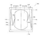
- the movable part 220 is configured in a shape in which both ends in a moving direction of a circular shape are cut off when seen in a plan view.
- the movable part 220 has an N-pole surface 221a magnetized with N poles in the thickness direction on the surface facing the planar coils 141 and 142, and an S pole in the thickness direction. And a magnetized south pole surface 222a.
- the movable part 220 is provided with an S pole surface 221b magnetized to an S pole in the thickness direction in a region corresponding to the N pole surface 221a on the surface opposite to the surface facing the planar coil 141 (142). It has been. In the region corresponding to the S pole surface 222a, an N pole surface 222b magnetized to the N pole in the thickness direction is provided.
- the linear motor 200 according to the second embodiment of the present invention can obtain the following effects in addition to the effects (1) to (13).
- the movable part 220 has a circular shape with both ends of the moving direction cut off. Therefore, compared with the case where a circular movable part is used, the moving amount (moving range) of the movable part 220 is widened by the range of the cut-off part, so that the range for accelerating the movable part 220 can be widened accordingly. . Therefore, the vibration amount of the linear motor 200 can be increased.
- the second embodiment is compared with the movable part 120 of the first embodiment that is in surface contact with the first side wall part 110b having a function as a guide. Since the movable part 220 of the form is in line contact with the first side wall part 110b, the frictional resistance can be reduced accordingly. Therefore, the movable part 220 can be operated more stably.
- the movable part 120 and the printed circuit board 140 are arranged inside a casing 310 formed in a rectangular cylindrical shape.
- the housing 310 is made of, for example, iron and has a function as a magnetic shield for suppressing the magnetism generated from the movable portion 120 from leaking to the outside.
- the printed circuit board 140 is slid from the opening 310a of the housing 310 and disposed inside, and then a lid (not shown) or the like is attached to the opening 310a. Further, openings 310b and 310c are formed in the housing 310 at positions corresponding to the electrode pads 170a and 170b of the printed circuit board 140.
- the linear motor 300 according to the third embodiment of the present invention can obtain the following effects in addition to the effects (1) to (15).
- the casing 310 having a function as a magnetic shield so as to cover the movable part 120 made of a permanent magnet, leakage of magnetic flux generated from the movable part 120 to the outside can be easily suppressed. .
- the frame, the bottom plate, and the housing as the yoke, the number of parts can be reduced as compared with the case where they are provided separately.
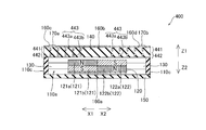
- the first portion 141a (141b) and the second portion 141c (141d) of the planar coil 141 are formed to have different widths. Differently, an example in which the widths of the first portion 441a (441b) and the second portion 441c (441d) of the planar coil 441 are equal will be described.
- the planar coil 441 including the current line 443 includes first portions 441a and 441b extending in the directions of arrows Y1 and Y2, and second portions 441c and 441d extending in the directions of arrows X1 and X2. And have.
- the width W3 of the first layer current line 443a constituting the first portions 441a and 441b of the planar coil 441 is substantially equal to the width W4 of the current line 443a constituting the second portions 441c and 441d.
- the pitch L4 of the current lines 443a constituting the second portions 441c and 441d (the distance between the centers of the adjacent current lines 443a) is smaller than the pitch L3 of the current lines 443a constituting the first portions 441a and 441b. It is configured.
- a part of the second portions 441c and 441d is arranged so as to overlap the first side wall portion 110b of the frame body 110 in plan view. That is, the arrangement area of the planar coil 441 is larger than the movable part 120 in a plan view and is arranged so as to cover the entire movable part 120.
- the structure of the second layer current line 443b (planar coil 442) shown in FIG. 11 is the same as that of the first layer current line 443a (planar coil 441).
- Other configurations of the fourth embodiment are the same as those of the first embodiment.
- the linear motor 400 according to the fourth embodiment of the present invention can obtain the following effects in addition to the effects (1) to (10) and (13) to (15).
- First portions 441a and 441b extending in a direction (arrow Y1 direction and arrow Y2 direction) intersecting the direction in which the movable unit 120 moves, and the direction in which the movable unit 120 moves (in the arrow X1 direction and the plane coil 441)
- Second portions 441c and 441d extending in the direction of arrow X2) were provided.
- the pitch L4 between the current lines 443a adjacent to the second portions 441c and 441d is configured to be smaller than the pitch L3 between the current lines 443a adjacent to the first portions 441a and 441b.
- the lengths of the first portions 441a and 441b in the direction of the arrow Y1 and the direction of the arrow Y2 increase as the pitch L4 of the second portions 441c and 441d decreases, so that the electromagnetic force for moving the movable portion 120 And the response time of the movable part 120 can be shortened.
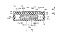
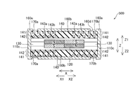
- the printed circuit board 140 on which the upper layer planar coil 141 and the lower layer 142 are arranged is arranged on one side (arrow Z1 direction) side in the thickness direction (Z direction) of the movable part 120.
- the movable portion 120 is disposed on the other side (arrow Z2 direction) side in the thickness direction (Z direction).
- the planar coil 141 is wound in a spiral shape counterclockwise from the outside to the inside in the same manner as the shape shown in FIG.
- the planar coil 142 is wound in a spiral shape counterclockwise from the inside to the outside in the same manner as the shape shown in FIG.
- the yoke 160a is not attached to the movable part 120, and instead, the yoke 160b is provided on both sides in the direction along the Z direction of the apparatus main body. Thereby, magnetic flux leakage from the linear motor 500 to the outside is suppressed. Further, yokes 160e are provided on both sides of the apparatus main body along the X direction. Thereby, magnetic flux leakage from the linear motor 500 to the outside is suppressed.
- a drive current is supplied to the current line 143 through the electrode pads 170a and 170b.
- the first portion 141 a (142 a) of the planar coil 141 (142) disposed on both sides in the thickness direction (Z direction) of the movable portion 120 is moved from the back side to the near side.
- Current flows.
- current flows from the front side to the back side of the first portion 141b (142b) of the planar coil 141 (142).
- the direction of the magnetic field generated between the N pole surface 121a and the S pole surface 122a of the movable portion 120 is the Z1 direction on the N pole surface 121a and the Z2 direction on the S pole surface 122a.
- the direction of the magnetic field generated between the N pole surface 122b and the S pole surface 121b of the movable portion 120 is the Z2 direction on the N pole surface 122b and the Z1 direction on the S pole surface 121b.
- the current flowing through the first portion 141a (142a) of the planar coil 141 (142) receives a force in the direction of the arrow X1 from the magnetic field of the N pole surface 121a and the S pole surface 121b of the first magnet 121.
- the current flowing through the first portion 141b (142b) of the planar coil 141 (142) receives a force in the direction of the arrow X1 from the magnetic field of the S pole surface 122a and the N pole surface 122b of the second magnet 122.
- the planar coil 141 (142) is fixed to the printed circuit board 140, the movable portion 120 is linearly moved in the direction of the arrow X2 by a reaction.
- the movable part 120 is linearly moved in the direction of the arrow X1 by the same action as described above. In this way, by switching the direction of the drive current at a predetermined frequency, the movable unit 120 is linearly moved alternately in the direction of the arrow X1 and the direction of the arrow X2 so as to resonate.
- the planar coils 141 and 142 are arranged on both sides of the movable portion 120 in the thickness direction (Z direction). Thereby, since the movable part 120 is driven by the electromagnetic force of the electric current which flows into the planar coils 141 and 142 arrange
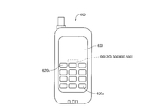
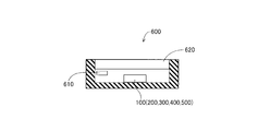
- the linear motor 100 (200 to 500) can be used in a mobile phone 600 or the like as shown in FIGS.
- the cellular phone 600 includes a linear motor 100 (200 to 500), a CPU 610 (see FIG. 15), and a display unit 620.
- the linear motor 100 (200 to 500) is disposed on the surface of the mobile phone 600 opposite to the side where the display unit 620 is disposed.
- the display unit 620 is configured by a touch panel panel, and is configured to operate the mobile phone 600 by pressing a button unit 620a displayed on the display unit 620.
- the linear motor 100 (200 to 500) vibrates when it is detected that the button unit 620a displayed on the display unit 620 is pressed or when the manner mode is set when a call is received. In this way, the CPU 610 controls.
- the mobile phone 600 is an example of the “mobile device” in the present invention.
- the mobile phone 600 can be made thinner as the linear motor 100 (200 to 500) is made thinner.
- the movable part 120 As an example of the movable part, the example using the rectangular movable part 120 whose corners are chamfered when viewed in plan is shown, but the present invention is not limited to this.
- a rectangular movable part that is not chamfered may be used as the movable part 120.
- the movable part 120 is configured by the N pole surface 121a, the S pole surface 122a, the S pole surface 121b, and the N pole surface 122b.
- the present invention is not limited to this. I can't.
- the movable part 120 may be configured by only the N pole surface 121a and the S pole surface 122a, and the S pole surface 121b and the N pole surface 122b may not be provided. That is, it is only necessary to provide magnetic pole surfaces magnetized with different magnetism along the surface facing the planar coils 141 and 142.
- the present invention is not limited to this.
- a weight such as tungsten may be disposed between the first magnet 121 and the second magnet 122.
- the movable part 120 can be more stably operated by the amount of the weight.
- the weight of the movable portion 120 can be increased while maintaining the same volume as compared with the case where the weight is not arranged. Thereby, the vibration amount of the movable part 120 can be increased easily.
- the yoke 160a may be arranged so as to extend from the surfaces of the S pole face 121b and the N pole face 122b to the side portions. In this case, magnetic flux leakage in the side surface direction (the directions of arrows X1 and X2 in FIG. 3) of the movable unit 120 can be reliably suppressed.
- the example in which the movable portion 120 is movably supported by the two leaf springs 130 as an example of the elastic member is shown, but the present invention is not limited to this.
- an elastic member other than a leaf spring such as a coil spring or a rubber member may be used.
- the movable part 120 may be supported by three or more leaf springs 130.
- the example in which the printed circuit board 140 on which the planar coils 141 and 142 are disposed is disposed only on one surface side of the movable portion 120, but the present invention is not limited to this.
- the printed circuit board 140 may be disposed on both surfaces of the movable unit 120. Thereby, since it drives from the both sides of the movable part 120, the driving force of the movable part 120 can be improved. As a result, the response time of the movable part 120 (time until the movable part 120 reaches a predetermined vibration amount) can be shortened.
- the yoke 160a is not attached to the movable portion 120, but instead the yoke 160b is provided on both sides of the apparatus main body, so that the linear motor 100 (200 It is preferable to suppress leakage of magnetic flux to the outside from .about.500).
- the present invention is not limited to this.
- the contact portion between the support portion 130c of the leaf spring 130 and the movable portion 120 may be bonded.
- the movable part 120 adheres as the shape is closer to a circle.
- the present invention is not limited to this.
- the frictional force between the movable part 120 and the first side wall part 110b and the frictional force between the movable part 120 and the bottom plate 150 are reduced by the amount of the magnetic fluid disposed, the movable part 120 is reduced.
- the response time can be shortened.
- all the pitches L2 of the second portions 141c (141d) of the planar coil 141 are smaller than the pitch L1 of the first portions 141a (141b) in plan view.
- the present invention is not limited to this.
- the pitch L2 of a part of the second part 141c (141d) may be formed to be smaller than the pitch L1 of the first part 141a (141b).
- a part of the second portion 141c (141d) of the planar coil 141 is arranged so as to overlap the first side wall portion 110b of the frame body 110 in plan view.
- the present invention is not limited to this. For example, you may provide all the 2nd parts 141c (141d) so that the 1st side wall part 110b of the frame 110 may overlap.
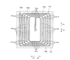
- the planar coil 141 (142) is formed in a spiral shape having a rectangular outline, but the present invention is not limited to this.
- the corner portion 141 e having a rectangular outline of the planar coil 141 may be formed at an angle other than a right angle, such as being formed obliquely.
- the movable portion 220 has a circular shape with both ends cut off.
- the corner portion 141e oblique as in the planar coil 141 of FIG. 16 the entire length of the current line 143a constituting the planar coil 141 can be shortened accordingly.
- the resistance value of the whole planar coil 141 can be reduced, the electric current which flows through the planar coil 141 can be increased.
- the force (electromagnetic force) acting between the planar coil 141 and the movable part 220 (permanent magnet) can be increased, so that the driving force of the movable part 220 can be increased and the movable part 220 Response time can be shortened.
- the widths of the second portions 141c (142c) and 141d (142d) are made larger than the widths of the first portions 141a (142a) and 141b (142b) of the planar coil 141 (142).
- the present invention is not limited to this.
- the first portions 141f and 141g and the second portions 141h and 141i may have the same width (W5).
- the widths of the first portions 141a and 141b and the second portions 141c and 141d are the same, and the line interval between the first portions 141a and 141b is different from the line interval between the second portions 141c and 141d. It may be.
- the widths of the second portions 141c (142c) and 141d (142d) are made larger than the widths of the first portions 141a (142a) and 141b (142b) of the planar coil 141 (142).
- the present invention is not limited to this.
- the first portions 141a and 141b and the second portions 141c and 141d have the same pitch, and the widths of the first portions 141a and 141b are larger than the widths of the second portions 141c and 141d. May be. Thereby, since the amount of current flowing through the first portions 141a and 141b increases, the driving force of the movable portion 120 can be further increased.
- the electromagnetic force is also reduced by the width of the second portions 141c and 141d that generate the electromagnetic force that moves the movable portion 120 in directions other than the movement path (arrow X1 and X2 directions). It is possible to suppress deviation from the movement route. Therefore, the linear motor 100 (200 to 500) can be stably operated.
Landscapes
- Engineering & Computer Science (AREA)
- Power Engineering (AREA)
- Reciprocating, Oscillating Or Vibrating Motors (AREA)
- Apparatuses For Generation Of Mechanical Vibrations (AREA)
Abstract
Description
本発明の第1実施形態によるリニアモータ(リニア駆動型振動モータ)100は、図1および図2に示すように、収納部110aが設けられた枠体110と、収納部110aに配置された可動部120と、可動部120を支持する一対の板バネ130とを備えている。なお、枠体110は、本発明の「筐体」の一例である。また、板バネ130は、本発明の「板バネ部材」の一例である。
図8を参照して、第2実施形態では、角部が面取りされた矩形形状の可動部120を用いた第1実施形態とは異なり、円形形状の移動方向の両端が切り落とされたような形状の可動部220を用いた例について説明する。
第3実施形態におけるリニアモータ300では、図9に示すように、枠部110、底板150およびヨーク160bをそれぞれ別途形成した第1実施形態とは異なり、枠部、底部およびヨークに対応する部分を一体的に形成する例について説明する。
第4実施形態では、図10および図11を参照して、平面コイル141の第1部分141a(141b)と第2部分141c(141d)とを異なる大きさの幅に形成した第1実施形態とは異なり、平面コイル441の第1部分441a(441b)と第2部分441c(441d)との幅の大きさを等しくする例について説明する。
第5実施形態では、図4、図5および図12を参照して、平面コイル141および142を備えたプリント基板140が可動部120の表面の一方側にのみ配置された第1実施形態とは異なり、プリント基板140を可動部120の表面の両側にそれぞれ配置する例について説明する。
本発明の第1~第5実施形態のいずれかによるリニアモータ100(200~500)は、図14および図15に示すように、携帯電話600などに用いることが可能である。携帯電話600は、リニアモータ100(200~500)と、CPU610(図15参照)と、表示部620とを備えている。リニアモータ100(200~500)は、携帯電話600の表示部620が配置された側とは反対側の面に配置されている。表示部620は、タッチパネル方式のパネルにより構成され、表示部620に表示されたボタン部620aを押圧することにより携帯電話600を操作するように構成されている。そして、リニアモータ100(200~500)は、表示部620に表示されたボタン部620aが押圧されたことを検知した場合や電話を着信した際にマナーモードに設定されている場合などに振動するようにCPU610で制御される。なお、携帯電話600は、本発明の「携帯機器」の一例である。
Claims (20)
- 渦巻状のコイル(141、142、441、442)と、
前記渦巻状のコイルと対向する面において第1の極性を有する第1磁極面(121a)および前記第1の極性とは異なる第2の極性を有する第2磁極面(122a)を含み、前記渦巻状のコイルの表面に沿った方向に移動可能に設けられる可動部(120、220)とを備えた、リニアモータ(100、200、300、400)。 - 前記可動部は、前記コイルの表面に沿った方向に直線的に移動するように構成され、
前記可動部の第1磁極面は、前記可動部の移動方向のうちの一方方向側に形成されているとともに、前記第2磁極面は前記可動部の移動方向のうちの他方方向側に形成されている、請求項1に記載のリニアモータ。 - 前記可動部は、前記コイルに対向する面と反対側の面において、前記第1磁極面に対応する位置に設けられた前記第2の極性を有する第3磁極面(121b)と、前記第2磁極面に対応する位置に設けられた前記第1の極性を有する第4磁極面(122b)とを含む、請求項1に記載のリニアモータ。
- 前記可動部の前記第1磁極面および前記第4磁極面は、N極またはS極のうちの一方を含み、
前記可動部の前記第2磁極面および前記第3磁極面は、N極またはS極のうちの他方を含む、請求項3に記載のリニアモータ。 - 前記可動部は、平面的に見て、角部が面取りされた矩形形状を有する、請求項1に記載のリニアモータ。
- 前記可動部は、平面的に見て、円形形状の移動方向の両端が切り落とされた形状を有する、請求項1に記載のリニアモータ。
- 前記渦巻状のコイルは、渦巻き状の平坦面状のコイルを含む、請求項1に記載のリニアモータ。
- 前記渦巻き状のコイルは、平面的に見て、1つの渦巻き状のコイルを含む、請求項1に記載のリニアモータ。
- 前記渦巻き状のコイルは、前記可動部の厚み方向の一方側に配置されている、請求項1に記載のリニアモータ。
- 前記渦巻き状のコイルは、前記可動部の厚み方向の一方方向側と他方方向側の両側に配置されている、請求項1に記載のリニアモータ。
- 前記渦巻き状のコイルは、平面的に見て、前記可動部の移動方向に直交する方向に沿って延びる第1部分(141a、141b、141f、141g、142a、142b、441a、441b)と、前記可動部の移動方向に沿って延びる第2部分(141c、141d、141h、141i、142c、142d、441c、441d)とを含む、請求項1に記載のリニアモータ。
- 前記渦巻き状のコイルは、平面的に見て、外側から内側に向かって渦巻き状に巻かれた上層の前記渦巻き状のコイル(141、441)と、内側から外側に向かって渦巻き状に巻かれた下層の前記渦巻き状のコイル(142、442)との2層構造に形成されており、
前記上層の渦巻き状のコイルの部分と、前記上層の渦巻き状のコイルの部分に対応する前記下層の渦巻き状のコイルの部分とには、同じ方向に電流が流れるように、前記上層の渦巻き状のコイルと前記下層の渦巻き状のコイルとが接続されている、請求項1に記載のリニアモータ。 - 前記可動部は、前記渦巻状のコイルと対向する面において前記第1の極性を有する第1磁極面および前記第1の極性とは異なる前記第2の極性を有する第2磁極面を有する永久磁石(121、122)を含み、
前記可動部は、前記可動部の前記永久磁石から発生する磁界と、前記渦巻き状のコイルに流れる電流とに基づいて、前記渦巻き状のコイルの表面に沿った方向に移動可能に構成されている、請求項1に記載のリニアモータ。 - 前記渦巻き状のコイルの矩形形状の輪郭の角部(141e)は、平面的に見て、斜めに形成されている、請求項1に記載のリニアモータ。
- 前記可動部の前記コイルに対向する面と反対側の面に設けられたヨーク(160a)をさらに備える、請求項1に記載のリニアモータ。
- 前記可動部を直線的に移動可能に支持するとともに、前記可動部に対する接触部が前記可動部の移動方向に沿って撓むように折り曲げられた板バネ部材(130)をさらに備え、
前記板バネ部材は、前記可動部の移動方向に沿って前記可動部に対して弾性力を加えるように構成されている、請求項1に記載のリニアモータ。 - 前記板バネ部材は、前記可動部の移動方向の両側に設けられている、請求項16に記載のリニアモータ。
- 前記板バネ部材は、前記可動部を支持する支持部(130c)を含み、
前記可動部は、平面的に見て、前記可動部の両側に設けられる板バネ部材の前記支持部に挟まれるように配置されている、請求項17に記載のリニアモータ。 - 前記可動部と、前記板バネ部材の前記支持部との接触部分は、接着されている、請求項18に記載のリニアモータ。
- 渦巻状のコイル(141、142、441、442)と、前記渦巻状のコイルと対向する面において第1の極性を有する第1磁極面(121a)および前記第1の極性とは異なる第2の極性を有する第2磁極面(122a)を有し、前記渦巻状のコイルの表面に沿った方向に移動可能に設けられる可動部(120、220)とを含むリニアモータ(100、200、300、400)を備えた、携帯機器(500)。
Priority Applications (3)
| Application Number | Priority Date | Filing Date | Title |
|---|---|---|---|
| CN2009801415894A CN102187552A (zh) | 2008-10-28 | 2009-08-10 | 线性电动机以及具备线性电动机的便携式设备 |
| US13/126,349 US20110204732A1 (en) | 2008-10-28 | 2009-08-10 | Linear motor and mobile device having linear motor |
| JP2010535713A JPWO2010050285A1 (ja) | 2008-10-28 | 2009-08-10 | リニアモータおよびリニアモータを備えた携帯機器 |
Applications Claiming Priority (2)
| Application Number | Priority Date | Filing Date | Title |
|---|---|---|---|
| JP2008277456 | 2008-10-28 | ||
| JP2008-277456 | 2008-10-28 |
Publications (1)
| Publication Number | Publication Date |
|---|---|
| WO2010050285A1 true WO2010050285A1 (ja) | 2010-05-06 |
Family
ID=42128653
Family Applications (1)
| Application Number | Title | Priority Date | Filing Date |
|---|---|---|---|
| PCT/JP2009/064106 Ceased WO2010050285A1 (ja) | 2008-10-28 | 2009-08-10 | リニアモータおよびリニアモータを備えた携帯機器 |
Country Status (4)
| Country | Link |
|---|---|
| US (1) | US20110204732A1 (ja) |
| JP (1) | JPWO2010050285A1 (ja) |
| CN (1) | CN102187552A (ja) |
| WO (1) | WO2010050285A1 (ja) |
Cited By (4)
| Publication number | Priority date | Publication date | Assignee | Title |
|---|---|---|---|---|
| US20120153748A1 (en) * | 2010-12-17 | 2012-06-21 | Tomokuni Wauke | Vibration generator |
| WO2016153029A1 (ja) * | 2015-03-26 | 2016-09-29 | 日本電産コパル株式会社 | 振動アクチュエータ |
| WO2018199150A1 (ja) * | 2017-04-27 | 2018-11-01 | 株式会社村田製作所 | アクチュエータ |
| JP2023517617A (ja) * | 2020-03-12 | 2023-04-26 | エルジー イノテック カンパニー リミテッド | 手ぶれ補正のためのコイル基板 |
Families Citing this family (14)
| Publication number | Priority date | Publication date | Assignee | Title |
|---|---|---|---|---|
| US9467033B2 (en) | 2012-02-07 | 2016-10-11 | Lg Electronics Inc. | Vibration motor and mobile terminal having the same |
| JP6029854B2 (ja) * | 2012-05-22 | 2016-11-24 | ミネベア株式会社 | 振動子及び振動発生器 |
| WO2015039047A1 (en) * | 2013-09-13 | 2015-03-19 | Resonant Systems, Inc. | Printed-circuit board motor |
| JP6253157B2 (ja) * | 2014-11-14 | 2017-12-27 | アルプス電気株式会社 | 振動発生装置 |
| CN204886637U (zh) * | 2015-07-31 | 2015-12-16 | 瑞声光电科技(常州)有限公司 | 振动电机 |
| CN204906151U (zh) * | 2015-07-31 | 2015-12-23 | 瑞声光电科技(常州)有限公司 | 振动电机 |
| CN207074948U (zh) * | 2017-04-14 | 2018-03-06 | 瑞声科技(新加坡)有限公司 | 振动器件 |
| CN208589889U (zh) * | 2018-08-03 | 2019-03-08 | 瑞声科技(南京)有限公司 | 线性振动电机 |
| CN208589892U (zh) * | 2018-08-03 | 2019-03-08 | 瑞声科技(南京)有限公司 | 振动电机 |
| CN208675083U (zh) * | 2018-08-03 | 2019-03-29 | 瑞声科技(南京)有限公司 | 线性振动电机 |
| JP2020043711A (ja) * | 2018-09-12 | 2020-03-19 | イビデン株式会社 | モーター用コイル基板とモーター、モーター用コイル基板の製造方法 |
| WO2020184108A1 (ja) * | 2019-03-12 | 2020-09-17 | アルプスアルパイン株式会社 | 電磁駆動装置及び操作装置 |
| CN111641310A (zh) * | 2020-06-17 | 2020-09-08 | 池州市弘港科技电子有限公司 | 一种微型超重低音双驱动低频振动器 |
| JP2022037328A (ja) * | 2020-08-25 | 2022-03-09 | イビデン株式会社 | コイル基板とモータ用コイル基板 |
Citations (4)
| Publication number | Priority date | Publication date | Assignee | Title |
|---|---|---|---|---|
| JPH052773U (ja) * | 1991-06-28 | 1993-01-19 | 株式会社トーキン | 振動発生装置 |
| JP2000224829A (ja) * | 1999-02-01 | 2000-08-11 | Sanyo Electric Co Ltd | リニア振動アクチュエータ |
| JP2007229680A (ja) * | 2006-03-03 | 2007-09-13 | Sanyo Electric Co Ltd | 往復振動発生器 |
| JP2007279408A (ja) * | 2006-04-07 | 2007-10-25 | Lasertec Corp | 直線駆動装置、可変シャッター装置、ビーム成形装置、ビーム照射装置、欠陥修正方法及びパターン基板の製造方法 |
Family Cites Families (2)
| Publication number | Priority date | Publication date | Assignee | Title |
|---|---|---|---|---|
| US4458227A (en) * | 1982-04-12 | 1984-07-03 | Polaroid Corporation | Electromagnetic actuators |
| JP2004261684A (ja) * | 2003-02-28 | 2004-09-24 | Citizen Electronics Co Ltd | 振動体及びその製造方法 |
-
2009
- 2009-08-10 WO PCT/JP2009/064106 patent/WO2010050285A1/ja not_active Ceased
- 2009-08-10 JP JP2010535713A patent/JPWO2010050285A1/ja active Pending
- 2009-08-10 CN CN2009801415894A patent/CN102187552A/zh active Pending
- 2009-08-10 US US13/126,349 patent/US20110204732A1/en not_active Abandoned
Patent Citations (4)
| Publication number | Priority date | Publication date | Assignee | Title |
|---|---|---|---|---|
| JPH052773U (ja) * | 1991-06-28 | 1993-01-19 | 株式会社トーキン | 振動発生装置 |
| JP2000224829A (ja) * | 1999-02-01 | 2000-08-11 | Sanyo Electric Co Ltd | リニア振動アクチュエータ |
| JP2007229680A (ja) * | 2006-03-03 | 2007-09-13 | Sanyo Electric Co Ltd | 往復振動発生器 |
| JP2007279408A (ja) * | 2006-04-07 | 2007-10-25 | Lasertec Corp | 直線駆動装置、可変シャッター装置、ビーム成形装置、ビーム照射装置、欠陥修正方法及びパターン基板の製造方法 |
Cited By (8)
| Publication number | Priority date | Publication date | Assignee | Title |
|---|---|---|---|---|
| US20120153748A1 (en) * | 2010-12-17 | 2012-06-21 | Tomokuni Wauke | Vibration generator |
| WO2016153029A1 (ja) * | 2015-03-26 | 2016-09-29 | 日本電産コパル株式会社 | 振動アクチュエータ |
| WO2018199150A1 (ja) * | 2017-04-27 | 2018-11-01 | 株式会社村田製作所 | アクチュエータ |
| JPWO2018199150A1 (ja) * | 2017-04-27 | 2019-06-27 | 株式会社村田製作所 | アクチュエータ |
| US10804784B2 (en) | 2017-04-27 | 2020-10-13 | Murata Manufacturing Co., Ltd. | Actuator |
| JP2023517617A (ja) * | 2020-03-12 | 2023-04-26 | エルジー イノテック カンパニー リミテッド | 手ぶれ補正のためのコイル基板 |
| JP7469500B2 (ja) | 2020-03-12 | 2024-04-16 | エルジー イノテック カンパニー リミテッド | 手ぶれ補正のためのコイル基板 |
| US12519360B2 (en) | 2020-03-12 | 2026-01-06 | Lg Innotek Co., Ltd. | Coil substrate for image stabilization |
Also Published As
| Publication number | Publication date |
|---|---|
| JPWO2010050285A1 (ja) | 2012-03-29 |
| US20110204732A1 (en) | 2011-08-25 |
| CN102187552A (zh) | 2011-09-14 |
Similar Documents
| Publication | Publication Date | Title |
|---|---|---|
| JPWO2010050285A1 (ja) | リニアモータおよびリニアモータを備えた携帯機器 | |
| WO2010026883A1 (ja) | リニアモータおよびリニアモータを備えた携帯機器 | |
| CN103516119B (zh) | 线性振动电机 | |
| CN102290953A (zh) | 线性振动器 | |
| WO2011013570A1 (ja) | 振動モータ | |
| JP2011205870A (ja) | 振動モータ | |
| JPWO2015068377A1 (ja) | 発電装置 | |
| JP2010239851A (ja) | 振動モータ及び携帯機器 | |
| KR102202568B1 (ko) | 진동 발생 장치 및 전자 기기 | |
| CN107171526A (zh) | 一种线性振动马达 | |
| WO2016167297A1 (ja) | リニア振動モータ | |
| JP2010082501A (ja) | リニアモータおよびリニアモータを備える携帯機器 | |
| CN212210810U (zh) | 线性马达 | |
| JP2019068589A (ja) | 振動モータ | |
| KR102782470B1 (ko) | 진동 액추에이터 및 접촉형 입력 장치 | |
| WO2010103929A1 (ja) | 振動モータおよび携帯機器 | |
| JP2010069470A (ja) | リニアモータおよびリニアモータを備えた携帯機器 | |
| JP2010051163A (ja) | リニアモータ | |
| WO2019098250A1 (ja) | 振動発生装置 | |
| WO2022062149A1 (zh) | 一种线性振动马达 | |
| JP2019025390A (ja) | 振動発生装置 | |
| JP2010029037A (ja) | リニアモータおよびリニアモータを備える携帯機器 | |
| JP2010207725A (ja) | 振動モータ及び携帯機器 | |
| JP2012034184A (ja) | スピーカ装置 | |
| JP2018207553A (ja) | 振動モータ |
Legal Events
| Date | Code | Title | Description |
|---|---|---|---|
| WWE | Wipo information: entry into national phase |
Ref document number: 200980141589.4 Country of ref document: CN |
|
| 121 | Ep: the epo has been informed by wipo that ep was designated in this application |
Ref document number: 09823398 Country of ref document: EP Kind code of ref document: A1 |
|
| WWE | Wipo information: entry into national phase |
Ref document number: 2010535713 Country of ref document: JP |
|
| WWE | Wipo information: entry into national phase |
Ref document number: 13126349 Country of ref document: US |
|
| NENP | Non-entry into the national phase |
Ref country code: DE |
|
| 122 | Ep: pct application non-entry in european phase |
Ref document number: 09823398 Country of ref document: EP Kind code of ref document: A1 |