WO2010044419A1 - 調光方法、調光システムおよび建造物 - Google Patents
調光方法、調光システムおよび建造物 Download PDFInfo
- Publication number
- WO2010044419A1 WO2010044419A1 PCT/JP2009/067776 JP2009067776W WO2010044419A1 WO 2010044419 A1 WO2010044419 A1 WO 2010044419A1 JP 2009067776 W JP2009067776 W JP 2009067776W WO 2010044419 A1 WO2010044419 A1 WO 2010044419A1
- Authority
- WO
- WIPO (PCT)
- Prior art keywords
- transparent sheet
- sheet layers
- layers
- transparent
- water vapor
- Prior art date
Links
Images


Classifications
-
- F—MECHANICAL ENGINEERING; LIGHTING; HEATING; WEAPONS; BLASTING
- F21—LIGHTING
- F21V—FUNCTIONAL FEATURES OR DETAILS OF LIGHTING DEVICES OR SYSTEMS THEREOF; STRUCTURAL COMBINATIONS OF LIGHTING DEVICES WITH OTHER ARTICLES, NOT OTHERWISE PROVIDED FOR
- F21V14/00—Controlling the distribution of the light emitted by adjustment of elements
- F21V14/06—Controlling the distribution of the light emitted by adjustment of elements by movement of refractors
-
- F—MECHANICAL ENGINEERING; LIGHTING; HEATING; WEAPONS; BLASTING
- F21—LIGHTING
- F21S—NON-PORTABLE LIGHTING DEVICES; SYSTEMS THEREOF; VEHICLE LIGHTING DEVICES SPECIALLY ADAPTED FOR VEHICLE EXTERIORS
- F21S11/00—Non-electric lighting devices or systems using daylight
-
- A—HUMAN NECESSITIES
- A01—AGRICULTURE; FORESTRY; ANIMAL HUSBANDRY; HUNTING; TRAPPING; FISHING
- A01G—HORTICULTURE; CULTIVATION OF VEGETABLES, FLOWERS, RICE, FRUIT, VINES, HOPS OR SEAWEED; FORESTRY; WATERING
- A01G9/00—Cultivation in receptacles, forcing-frames or greenhouses; Edging for beds, lawn or the like
- A01G9/14—Greenhouses
- A01G9/1407—Greenhouses of flexible synthetic material
- A01G9/1415—Greenhouses of flexible synthetic material with double or multiple walls
-
- A—HUMAN NECESSITIES
- A01—AGRICULTURE; FORESTRY; ANIMAL HUSBANDRY; HUNTING; TRAPPING; FISHING
- A01G—HORTICULTURE; CULTIVATION OF VEGETABLES, FLOWERS, RICE, FRUIT, VINES, HOPS OR SEAWEED; FORESTRY; WATERING
- A01G9/00—Cultivation in receptacles, forcing-frames or greenhouses; Edging for beds, lawn or the like
- A01G9/20—Forcing-frames; Lights, i.e. glass panels covering the forcing-frames
-
- A—HUMAN NECESSITIES
- A01—AGRICULTURE; FORESTRY; ANIMAL HUSBANDRY; HUNTING; TRAPPING; FISHING
- A01G—HORTICULTURE; CULTIVATION OF VEGETABLES, FLOWERS, RICE, FRUIT, VINES, HOPS OR SEAWEED; FORESTRY; WATERING
- A01G9/00—Cultivation in receptacles, forcing-frames or greenhouses; Edging for beds, lawn or the like
- A01G9/22—Shades or blinds for greenhouses, or the like
- A01G9/225—Inflatable structures
-
- G—PHYSICS
- G02—OPTICS
- G02B—OPTICAL ELEMENTS, SYSTEMS OR APPARATUS
- G02B5/00—Optical elements other than lenses
-
- G—PHYSICS
- G02—OPTICS
- G02B—OPTICAL ELEMENTS, SYSTEMS OR APPARATUS
- G02B26/00—Optical devices or arrangements for the control of light using movable or deformable optical elements
- G02B26/02—Optical devices or arrangements for the control of light using movable or deformable optical elements for controlling the intensity of light
-
- Y—GENERAL TAGGING OF NEW TECHNOLOGICAL DEVELOPMENTS; GENERAL TAGGING OF CROSS-SECTIONAL TECHNOLOGIES SPANNING OVER SEVERAL SECTIONS OF THE IPC; TECHNICAL SUBJECTS COVERED BY FORMER USPC CROSS-REFERENCE ART COLLECTIONS [XRACs] AND DIGESTS
- Y02—TECHNOLOGIES OR APPLICATIONS FOR MITIGATION OR ADAPTATION AGAINST CLIMATE CHANGE
- Y02A—TECHNOLOGIES FOR ADAPTATION TO CLIMATE CHANGE
- Y02A40/00—Adaptation technologies in agriculture, forestry, livestock or agroalimentary production
- Y02A40/10—Adaptation technologies in agriculture, forestry, livestock or agroalimentary production in agriculture
- Y02A40/25—Greenhouse technology, e.g. cooling systems therefor
Definitions
- the present invention relates to a light control method, a light control system, and a building.
- a plant cultivation house As a building whose roof or wall is made of a transparent sheet or transparent film, there are a plant cultivation house, a livestock barn, an aquaculture facility, a sports facility, and the like. In the building, for various reasons, it is required to adjust the amount of light incident on the building. For example, in a house for plant cultivation, in the morning when plants actively synthesize, as much light as possible enters the house, while in the daytime, to suppress the temperature rise and plant stress in the house , Excessive light may not be incident.
- a panel material including two transparent films, a frame for holding them airtight, and a vacuum pump and an air pump connected to a space surrounded by these (see Patent Document 1).
- the amount of light transmitted through the two transparent films is increased by reducing the space between the two transparent films with a vacuum pump and bringing the two transparent films into close contact with each other.
- the amount of light transmitted through the two transparent films hardly changed before and after the two transparent films were brought into close contact with each other.
- An object of the present invention is to provide a dimming method, a dimming system, and a building including the dimming system that can increase in a short time the amount of light transmitted through a multiple sheet composed of a plurality of transparent sheet layers. Furthermore, the object of the present invention is to reduce the amount of light transmitted through the multiple sheet composed of a plurality of transparent sheet layers, and then increase the amount of light transmitted through the multiple sheet in a short time to the level before reducing the amount of light.
- the light control method of the present invention is a light control method for adjusting the amount of light transmitted through a multiple sheet composed of a plurality of transparent sheet layers arranged opposite to each other, and (a) supplies moisture between the transparent sheet layers of the multiple sheet. And (b) after the step (a), the step of reducing the pressure between the transparent sheet layers of the multiple sheets and bringing the transparent sheet layers into close contact with each other in a state where moisture exists between the transparent sheet layers. And
- the step (a) is a step of (a1) supplying water vapor and / or mist between the transparent sheet layers of the multiple sheet to generate condensation on the opposing surface of the transparent sheet layer.
- the transparent sheet layer of the multiple sheet is depressurized, and moisture derived from water vapor and / or mist is present between the transparent sheet layers, It is preferable that the transparent sheet layers be in close contact with each other.
- the light control method of the present invention is preferably a method of adjusting the amount of light transmitted through the multiple sheet in a building in which at least a part of the roof and / or wall is composed of the multiple sheet.
- the material of the transparent sheet layer is preferably fluororesin, vinyl chloride resin, polyester, polyethylene, ethylene-vinyl acetate copolymer (hereinafter referred to as EVA), polyethylene terephthalate, acrylic resin, or polycarbonate.
- EVA ethylene-vinyl acetate copolymer
- ETFE ethylene-tetrafluoroethylene copolymer
- FEP hexafluoropropylene-tetrafluoroethylene copolymer
- THV perfluoro (alkyl vinyl ether)- A tetrafluoroethylene copolymer
- THV tetrafluoroethylene-hexafluoropropylene-vinylidene fluoride copolymer
- THV tetrafluoroethylene-hexafluoropropylene-vinylidene fluoride copolymer
- THV tetrafluoroethylene-hexafluoropropylene-vinylidene fluoride copolymer
- the total light transmittance of the transparent sheet layer is preferably 80% or more.
- the light control system of the present invention is a light control system that adjusts the amount of light transmitted through a multiple sheet composed of a plurality of transparent sheet layers arranged opposite to each other, wherein moisture is supplied between the multiple sheet and the transparent sheet layer of the multiple sheet. It is characterized by comprising water supply means for supplying and pressure reducing means for reducing the pressure between the transparent sheet layers of the multiple sheets.
- the water supply means is preferably a water vapor supply means for supplying water vapor or a mist supply means for supplying mist.
- the material of the transparent sheet layer and the fluororesin used in the light control system of the present invention are preferably the same as those of the light control method, and the total light transmittance of the transparent sheet layer is preferably the same as described above. .
- the building of the present invention is a building provided with the light control system of the present invention, wherein at least a part of a roof and / or a wall is composed of the multiple sheets.
- the light control method of the present invention it is possible to increase the amount of light transmitted through a multiple sheet composed of a plurality of transparent sheet layers in a short time.
- the amount of light transmitted through the multiple sheets can be reduced, and then the amount of light transmitted through the multiple sheets is reduced. It can be increased in a short time to a level higher than the previous level.
- the light control system of the present invention it is possible to increase the amount of light transmitted through a multiple sheet composed of a plurality of transparent sheet layers in a short time.
- the means for supplying moisture between the transparent sheets of the multiple sheets is a means for supplying water vapor and / or mist, the amount of light transmitted through the multiple sheets can be reduced, and then the multiple sheets The amount of light that passes through can be increased in a short time to the level before the amount of light is reduced.
- the amount of light incident on the building can be increased in a short time.
- the means for supplying moisture between the transparent sheet layers of the multiple sheets is a means for supplying water vapor and / or mist
- the amount of light incident on the building can be reduced, and then the amount of light is reduced.
- the amount of light incident on the building can be increased in a short time to a level before the generation.
- the dimming method, dimming system of the present invention, and the building provided with the dimming system of the present invention include a building in which a roof or a wall such as a plant cultivation house is formed of a transparent sheet or a transparent film. Useful for.
- the “sheet” in this specification includes what is called a relatively thin “film”.
- “opposing arrangement” means that the transparent sheet layers are arranged so as to overlap each other when viewed from a direction orthogonal to the surface of the transparent sheet layer, and a part or all of the transparent sheet layers are in close contact with each other. It means that there is no state. It is sufficient that a space can be formed between the transparent sheet layers when a gas (air or the like) is supplied, and there may be no visible gap between the transparent sheet layers before the gas is supplied.
- “at least part of a roof and / or wall” includes a window provided on the roof or wall.
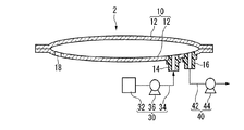
- FIG. 1 is a cross-sectional view showing an example of the light control system of the present invention.
- the light control system 1 includes two transparent sheet layers 12 arranged to face each other, and one transparent sheet layer 12 is provided with an air supply port 14, a first exhaust port 16, and a second exhaust port 18.
- a frame member 20 that hermetically holds the periphery of the two transparent sheet layers 12, a water vapor supply means 30 (water supply means) that supplies water vapor between the transparent sheet layers 12 of the multiple sheet 10,
- a pressure reducing means 40 for reducing the pressure between the transparent sheet layers 12 is provided.
- the water vapor supply means 30 includes a water vapor generator 32, an air supply passage 34 that connects the water vapor generator 32 and the air supply port 14 of the multiple sheet 10, and a blower 36 that is provided in the middle of the air supply passage 34. It is a thing. Examples of the steam generator include those provided with a heater (such as a heater) and a water bath, and commercially available humidifiers.
- the decompression means 40 includes an exhaust passage 42 whose one end is connected to the first exhaust port 16 of the multiple sheet 10 and a vacuum pump 44 provided in the middle of the exhaust passage 42.
- the transparent sheet layer 12 may be made of a material that transmits light.
- An example of the material is a transparent resin. If at least one of the transparent sheet layers 12 is a flexible sheet made of a transparent resin, the other may be a glass plate or a resin plate.
- the transparent resin is preferably a thermoplastic resin such as fluororesin, vinyl chloride resin, polyester, polyethylene, ethylene-vinyl acetate copolymer (hereinafter referred to as EVA), polyethylene terephthalate, acrylic resin, polycarbonate, and the like. From the viewpoints of mechanical strength, weather resistance, ultraviolet resistance, heat resistance, weldability, etc., a fluororesin is preferred.
- fluororesins examples include ethylene-tetrafluoroethylene copolymer (hereinafter referred to as ETFE), hexafluoropropylene-tetrafluoroethylene copolymer (hereinafter referred to as FEP), perfluoro (alkyl vinyl ether) -tetrafluoro.
- ETFE ethylene-tetrafluoroethylene copolymer
- FEP hexafluoropropylene-tetrafluoroethylene copolymer
- THV tetrafluoroethylene-hexafluoropropylene-vinylidene fluoride copolymer
- THV tetrafluoroethylene-hexafluoropropylene-vinylidene fluoride copolymer
- THV tetrafluoroethylene-hexafluoropropylene-vinylidene fluoride copolymer
- THV tetrafluoroethylene-hex
- the transparent sheet layer 12 may be a single layer sheet or a laminated sheet.
- the laminated sheet include a three-layer sheet in which a polyethylene layer, an EVA layer, and a polyethylene layer are laminated in this order.
- the transparent sheet layer 12 may be subjected to a surface treatment.
- the surface treatment include hydrophilic treatment, antifouling treatment, water repellent treatment and the like.
- a hydrophilic treatment method a method of applying a hydrophilizing agent (inorganic colloid, hydrophilic resin, metal oxide, etc.) to the surface of the transparent sheet layer 12, a metal (silicon, tin, And a method of sputtering an oxide of titanium and the like.
- Both sides of the transparent sheet layer 12 facing each other inside the multiple sheet 10 may be hydrophilic surfaces, and one of the opposing surfaces is hydrophilic. Alternatively, both of the opposing surfaces may be non-hydrophilized surfaces.
- the thickness of the transparent sheet layer 12 made of a transparent resin is preferably 800 ⁇ m or less, and more preferably 700 ⁇ m or less from the viewpoints of transparency and workability. Further, in terms of mechanical strength and the like, 20 ⁇ m or more is preferable, and 40 ⁇ m or more is more preferable.
- the thickness of the transparent sheet layer 12 made of glass is preferably 3 mm to 10 mm.
- the total light transmittance of the transparent sheet layer 12 is preferably 80% or more, more preferably 85% or more, and particularly preferably 90% or more. When the total light transmittance is 70% or more, it is easy to secure light necessary for plant photosynthesis.
- the upper limit of the total light transmittance of the transparent sheet layer 12 is not particularly limited.
- the total light transmittance of the transparent sheet layer 12 is measured in accordance with JIS K7361-1.
- the total light transmittance of the multiple sheet 10 is preferably adjusted to be 80% or more, more preferably 85% or more, and particularly preferably 90% or more, in order to increase the amount of light transmitted through the multiple sheet. On the other hand, when it is desired to reduce the amount of light transmitted through the multiple sheets, the amount may be adjusted to 50 to 80%.
- the light control system 1 described above includes the water vapor supply means 30 that supplies water vapor between the transparent sheet layers 12 of the multiple sheet 10, dew condensation is generated on the opposite surface of the transparent sheet layer 12, and The amount of light transmitted through the sheet 10 can be reduced as compared to before supplying water vapor between the transparent sheet layers 12.
- the pressure reducing means 40 for reducing the pressure between the transparent sheet layers 12 of the multiple sheet 10 is provided, the pressure between the transparent sheet layers 12 of the multiple sheet 10 is reduced, and moisture derived from water vapor exists between the transparent sheet layers 12.
- the amount of light transmitted through the multiple sheets 10 can be increased in a short time to a level before supplying water vapor between the transparent sheet layers 12.
- the light control system of the present invention includes a multiple sheet composed of a plurality of transparent sheet layers arranged opposite to each other, a moisture supply means for supplying moisture between the transparent sheet layers of the multiple sheet, and a reduced pressure between the transparent sheet layers of the multiple sheet. 1 is not limited to the light control system 1 shown in FIG.
- the multiple sheet 10 has a bag-like shape in which the periphery of the two transparent sheet layers 12 is heat-sealed without providing a frame material on the periphery of the two transparent sheet layers 12 as in the light control system 2 shown in FIG. It may be a thing.
- the bag-like multiple sheet may be one obtained by folding a single transparent sheet in half and heat-sealing three sides to form a multiple sheet composed of two transparent sheet layers. You may heat-seal the opening of both ends and make it the multiple sheet
- the air supply port and the exhaust port may be combined into one air supply / exhaust port, and the water supply unit and the pressure reducing unit may be connected to the air supply / exhaust port in a switchable manner.
- a plurality of multiple sheets are juxtaposed with the multiple sheets in communication with communication means (communication pipes, communication slits, etc.), and at least one of the multiple sheets is provided with an air supply port to supply moisture.
- the pressure reducing means may be connected by providing an exhaust port in at least one of the multiple sheets.
- the number of transparent sheet layers is not limited to 2, and may be 3 or more. In view of light transmittance, cost, etc., 2 to 5 is preferable, and 2 to 3 is particularly preferable.
- the water supply means is not limited to the water vapor supply means 30 shown in FIG. 1, and may be a mist supply means including a mist generating device, an air supply passage, and a blower, and includes a water tank and a liquid feed pump.
- the running water supply means provided may be sufficient.
- the amount of light transmitted through the multiple sheet 10 is sufficiently larger than that before supplying the flowing water between the transparent sheet layers 12 as in the case where the water vapor supply means 30 and the mist supply means are provided. It cannot be reduced.
- the light control method of the present invention is a method having the following steps (a) to (c).
- C After the step (b), by forming a gas layer between the transparent sheet layers as necessary, the step of returning the amount of light transmitted through the multiple sheets to a level before supplying moisture between the transparent sheet layers .
- the surface of the multiple sheets facing the transparent sheet layers is at least One gets wet with moisture. Any moisture can be used as long as it can wet the surface of the transparent sheet layer. Examples of the water include water (running water), water vapor, and mist. When water vapor and / or mist is supplied as moisture, a light shielding effect and a heat shielding effect can be expected for the following reasons.
- the transparent sheet layers of the multiple sheets are depressurized, and the transparent sheet is in a state where moisture exists between the transparent sheet layers. Since the sheet layers are brought into close contact with each other, the amount of light transmitted through the multiple sheets can be increased in a short time to a level before supplying moisture between the transparent sheet layers.
- the dimming method using the dimming system 1 includes the following steps (a1) to (c1). (A1) By supplying water vapor and / or mist between the transparent sheet layers 12 of the multiple sheet 10 and generating condensation on the opposite surface of the transparent sheet layer 12, the amount of light transmitted through the multiple sheet 10 is changed to the transparent sheet layer 12 The process of lowering than before supplying water vapor and / or mist in between.
- step (B1) After the step (a1), the pressure between the transparent sheet layers 12 of the multiple sheet 10 is reduced, and the transparent sheet layers 12 are brought into close contact with each other in a state where moisture derived from water vapor and / or mist exists between the transparent sheet layers 12. Increasing the amount of light transmitted through the multiple sheet 10 by increasing the amount of water before the water vapor and / or mist is supplied between the transparent sheet layers 12. (C1) A step of returning the amount of light transmitted through the multiple sheets to a level before supplying water vapor between the transparent sheet layers by forming a gas layer between the transparent sheet layers as necessary after the step (b). .
- Step (a1) In the multiplex sheet 10 in a normal state, a gas layer is formed between the transparent sheet layers 12 for the purpose of heat insulation and the like.
- the water vapor generating device 32 and the blower 36 are operated to include water vapor generated from the water vapor generating device 32 (and mist in which a part of the water vapor is aggregated).
- gas is supplied between the transparent sheet layers 12 of the multiple sheet 10 from the air supply port 14 via the air supply flow path 34, the gas between the transparent sheet layers 12 is expelled from the second exhaust port 18, and then the transparent sheet layer Between 12 is filled with a gas containing water vapor, and condensation occurs on at least one of the opposing surfaces of the transparent sheet layer 12.
- Condensation generated on the opposing surface of the transparent sheet layer 12 reflects and scatters light, and thus can exhibit a light shielding effect. Therefore, the amount of light transmitted through the multiple sheet 10 can be reduced as compared to before supplying water vapor between the transparent sheet layers 12. Moreover, since the dew condensation which generate
- Step (b1) In a state where condensation occurs on at least one of the opposing surfaces of the transparent sheet layer 12, the water vapor generating device 32 and the blower 36 are stopped, and then the decompression means 40 is operated, and the space between the transparent sheet layers 12 from the first exhaust port 16. The gas is exhausted, and the space between the transparent sheet layers 12 is reduced. Thereby, the transparent sheet layers 12 are in close contact with each other in a state where moisture exists between the transparent sheet layers 12, and the amount of light transmitted through the multiple sheet 10 is increased as compared with that before water vapor is supplied between the transparent sheet layers 12.
- Step (c1) When the decompression means 40 is stopped, a gas layer is formed between the transparent sheet layers 12 without applying pressure between the transparent sheet layers 12. Moisture existing between the transparent sheet layers 12 is drained from the air supply port 14, the first exhaust port 16, the second exhaust port 18, or a water-permeable sheet provided as necessary. By forming a gas layer between the transparent sheet layers 12, the amount of light transmitted through the multiple sheet 10 can be returned to the level before the water vapor is supplied between the transparent sheet layers 12.
- water vapor is supplied between the transparent sheet layers 12 of the multiplex sheet 10 to cause condensation on the opposite surface of the transparent sheet layer 12.
- the amount of light transmitted through the sheet 10 can be reduced as compared to before supplying water vapor between the transparent sheet layers 12.
- the pressure between the transparent sheet layers 12 of the multiple sheet 10 is reduced, and the transparent sheet layers 12 are brought into close contact with each other in a state where moisture derived from water vapor exists between the transparent sheet layers 12, the amount of light transmitted through the multiple sheet 10 Can be increased to a level before the water vapor is supplied between the transparent sheet layers 12.
- the building of this invention is a building provided with the light control system of this invention, Comprising: At least one part of a roof and / or a wall is comprised with the multiple sheet
- Buildings include plant cultivation houses (agricultural houses, horticultural houses, etc.), livestock houses (cattlehouses, pig farms, chicken farms, etc.), fish farming facilities, sports facilities (gymnasiums, pools, tennis courts) , A soccer field, a baseball field, etc.), and a plant cultivation house is preferable because it is important to adjust the indoor environment such as light and temperature.
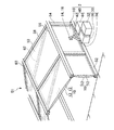
- FIG. 3 is a perspective view and a sectional view showing an example of an agricultural house.
- the agricultural house 50 includes the above-described dimming system 1, and the roof and walls are configured by the multiple sheets 10 of the dimming system 1.
- the farm house 50 includes a base 52, a pillar 54, a girder 56, a rafter 58, a rafter 58, a purlin 60, a beam 62, and the like, and the base 52, the pillar 54, a girder 56, a rafter 58, and a purlin.
- a water vapor supply means 30 (water supply means) for supplying water vapor and a pressure reducing means 40 for reducing the pressure between the transparent sheet layers 12 of the multiple sheet 10 are provided.
- the water vapor supply means 30 includes a water vapor generator 32, an air supply passage 34 that connects the water vapor generator 32 and the air supply port 14 of the multiple sheet 10, and a blower 36 that is provided in the middle of the air supply passage 34. It is a thing.
- the decompression means 40 includes an exhaust passage 42 whose one end is connected to the first exhaust port 16 of the multiple sheet 10 and a vacuum pump 44 provided in the middle of the exhaust passage 42.
- Examples of the base 52, the pillar 54, the girder 56, the rafter 58, the purlin 60, the beam 62, and the like that form the skeleton of the agricultural house 50 include metal pipes, metal molds (angle members, square members, etc.) and the like. It is done. These are connected by tight fittings (orthogonal clamps, universal clamps, etc.).
- the columns 54, girders 56, rafters 58, purlins 60, etc. that exist between the multiple sheets 10 are provided with communication means (not shown) such as communication pipes, communication slits, etc. for connecting the multiple sheets 10 to each other. Is preferred.
- the number of the air supply ports 14, the first exhaust ports 16 and the second exhaust ports (not shown) provided in the transparent sheet layer 12, the water vapor supply means 30 and the pressure reducing means are provided.
- the number of 40 can be minimized.
- the dimming method in the agricultural house 50 may be performed in the same manner as the dimming method using the dimming system 1 described above.
- the agricultural house 50 described above includes the water vapor supply means 30 for supplying water vapor between the transparent sheet layers 12 of the multiple sheet 10 constituting the roof and the wall, the opposite surface of the transparent sheet layer 12 is provided. Condensation is generated, and the amount of light transmitted through the multiple sheet 10 can be reduced as compared to before supplying water vapor between the transparent sheet layers 12. As a result, the amount of light incident on the agricultural house 50 can be reduced.
- the pressure reducing means 40 for reducing the pressure between the transparent sheet layers 12 of the multiple sheet 10 is provided, the pressure between the transparent sheet layers 12 of the multiple sheet 10 is reduced, and moisture derived from water vapor exists between the transparent sheet layers 12.
- the amount of light transmitted through the multiple sheets 10 can be increased in a short time to a level before supplying water vapor between the transparent sheet layers 12.
- the amount of light incident on the agricultural house 50 can be increased in a short time.
- the building of this invention is a building provided with the light control system of this invention, Comprising: At least one part of a roof and / or a wall is comprised with the multiple sheet
- the light control system 2 described above may be provided instead of the light control system 1.
- the air supply port 14 and the first exhaust port 16 are combined into one air supply / exhaust port, and the water vapor supply means 30 and the pressure reducing means 40 are connected to the air supply / exhaust port in a switchable manner. May be.
- the roof may have a semicircular cross section.
- the shape of the agricultural house may be a semicircular cross section in which the roof and the wall are integrated.
- Total light transmittance The total light transmittance of the transparent sheet layer was measured according to JIS K7361-1.
- Example 1 The illuminance measurements in Examples 1 to 3 were performed in a room where temperature was 25 ° C., relative humidity (hereinafter referred to as RH): 33%, and outside light was blocked.
- RH relative humidity
- ETFE film (A) with a hydrophilic treatment on one side (Asahi Glass Co., Ltd., FClean 100WT, thickness: 100 ⁇ m, length: 1250 mm, width: 1250 mm, total light transmittance: 93 to 94%) and hydrophilic treatment No ETFE film (B) (manufactured by Asahi Glass Co., Ltd., Fclean 100NT, thickness: 100 ⁇ m, length 1250 mm, width 1250 mm, total light transmittance: 93 to 94%) was prepared.
- the hydrophilization treatment was performed by a method of applying a hydrophilizing agent (metal oxide type).
- One air supply / exhaust port (C) is provided in the vicinity of the center of the ETFE film (A) in the horizontal direction and in the vicinity of the lower end in the vertical direction.
- One exhaust port (D) was provided near the upper end.
- the ETFE film (A) and the ETFE film (B) are stacked so that the hydrophilic treated surface of the ETFE film (A) is on the inner side, and the peripheral edge of these films is a frame material composed of a receiving member and a holding member.
- the film was sandwiched in an airtight manner (length: 1150 mm, width: 1150 mm) to produce a multiple film.
- a light source lamp (manufactured by Toshiba Lighting & Technology Corp., reflection type positive lamp DR400 / T (L)) was installed on the ETFE film (A) side of the multiple film.
- an illuminance meter (manufactured by Eiko Seiki Co., Ltd., MS-720, spectroradiometer) was installed on the ETFE film (B) side of the multiple film.
- the light source lamp and the illuminance meter were installed so that the straight line connecting the light emitting portion of the light source lamp and the sensor portion of the illuminance meter was orthogonal to the surface of the multiple film and passed through the center of the multiple film.
- the distance between the light emitting part of the light source lamp and the multiple film was 450 mm
- the distance between the sensor part of the illuminometer and the multiple film was 320 mm.
- Example 2 Next, one end of a tube (vinyl chloride resin, inner diameter: 25 mm) was connected to the air supply / exhaust port (C), and the other end of the tube was connected to a vacuum cleaner (NC-103, 100V, 1050W, manufactured by Nicron Industrial Co., Ltd.) Connected to.
- the vacuum cleaner was operated, the pressure between the ETFE film (A) and the ETFE film (B) was reduced, and the ETFE film (A) and the ETFE film (B) were brought into close contact with each other.
- Example 3 Next, the other end of the tube was connected to a blower (ELECTRIC BLOWER, size: 30 ⁇ , 50/60 Hz, 55/51 W, manufactured by Yodogawa Electric Manufacturing Co., Ltd.). Further, a water bath installed on an IT stove (manufactured by Hitachi, Ltd., MH-B1, 100 V, 1350 W) was placed in a transparent resin casing, and the casing and the blower were connected. The air blower was operated, and air containing water vapor was supplied between the ETFE film (A) and the ETFE film (B) to cause condensation on the inner surface of the multiple sheet.
- a blower ELECTRIC BLOWER, size: 30 ⁇ , 50/60 Hz, 55/51 W, manufactured by Yodogawa Electric Manufacturing Co., Ltd.
- a water bath installed on an IT stove manufactured by Hitachi, Ltd., MH-B1, 100 V, 1350 W
- the air blower was operated, and air containing water vapor was supplied between the ETFE film (A) and
- the other end of the tube was connected to a vacuum cleaner (NC-103, 100 V, 1050 W, manufactured by Nicron Industrial Co., Ltd.).
- the vacuum cleaner is activated to reduce the pressure between the ETFE film (A) and the ETFE film (B), and in the state where moisture exists between the ETFE film (A) and the ETFE film (B), the ETFE film (A ) And the ETFE film (B).
- the amount of light transmitted through the multiple film is such that the ETFE film (A) and the ETFE film (A) are in close contact with the ETFE film (B) (Example 2). It was almost the same as the state (Example 1) in which the film (B) simply overlapped. On the other hand, in the state (Example 3) in which the ETFE film (A) and the ETFE film (B) are in close contact with each other through a thin film of water, the amount of light transmitted through the multiple film was increased as compared with Examples 1 and 2.
- Example 4 The illuminance measurement in Example 4 was performed outdoors on a sunny day in September 2008.
- a multiple film was produced in which the peripheral edges of the ETFE film (A) and the ETFE film (B) were hermetically sandwiched by a frame material composed of a receiving member and a holding member.
- the multi-film was installed outdoors so that the surface of the multiplex film faced to the south and the inclination angle was 45 °.
- an illuminance meter manufactured by Eiko Seiki Co., Ltd., MS-720, spectroradiometer
- the distance between the sensor unit of the illuminometer and the multiple film was 300 mm.
- a tube (vinyl chloride resin, inner diameter: 25 mm) is connected to the air supply / exhaust port (C), and the other end of the tube is connected to a blower (ELECTRIC BLOWER, manufactured by Yodogawa Electric Co., Ltd., size: 30 ⁇ , 50/60 Hz, 55 / 51W).
- a water bath installed on an IT stove (manufactured by Hitachi, Ltd., MH-B1, 100 V, 1350 W) was placed in a transparent resin casing, and the casing and the blower were connected. The air blower was operated and air containing water vapor was supplied between the ETFE film (A) and the ETFE film (B).
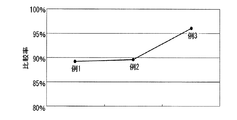
- the change in illuminance over time was measured on the sun side of the multiple film and on the opposite side of the sun across the multiple film, and the comparison rate was determined. The results are shown in FIG. As the condensation generated on the inner surface of the multiple sheet increased, the amount of light transmitted through the multiple sheet decreased.
- the other end of the tube was connected to a vacuum cleaner (NC-103, 100 V, 1050 W, manufactured by Nicron Industrial Co., Ltd.).
- the vacuum cleaner was actuated to reduce the pressure between the ETFE film (A) and the ETFE film (B).
- the change in illuminance over time was measured on the sun side of the multiple film and on the opposite side of the sun across the multiple film, and the comparison rate was determined. The results are shown in FIG.
- the ETFE film (A) and the ETFE film (B) were brought into close contact with each other through a thin film of water, and the amount of light transmitted through the multiple film increased in a short time.
- seat at that time exceeded the level before the supply start of the air containing water vapor
- Example 5 The measurement of illuminance in Example 5 was performed in a room where temperature was 25 ° C., RH was 33%, and external light was blocked. In the same manner as in Example 1, a multiple film was produced in which the peripheral edges of the ETFE film (A) and the ETFE film (B) were hermetically sandwiched by a frame material composed of a receiving member and a holding member.
- a light source lamp manufactured by Matsushita Electric Industrial Co., Ltd., National Sakai High Lamp 300W type
- an illuminometer manufactured by Tokyo Kogyo Co., Ltd., ANA-F11, general class A illuminometer
- the light source lamp and the illuminance meter were installed so that the straight line connecting the light emitting portion of the light source lamp and the sensor portion of the illuminance meter was orthogonal to the surface of the multiple film and passed through the center of the multiple film.
- the distance between the light emitting part of the light source lamp and the multiple film was 450 mm
- the distance between the sensor part of the illuminometer and the multiple film was 320 mm.
- a tube (vinyl chloride resin, inner diameter: 25 mm) is connected to the air supply / exhaust port (C), and the other end of the tube is connected to a blower (ELECTRIC BLOWER, manufactured by Yodogawa Electric Co., Ltd., size: 30 ⁇ , 50/60 Hz, 55 / 51W).
- a water bath installed on an IT stove (manufactured by Hitachi, Ltd., MH-B1, 100 V, 1350 W) was placed in a transparent resin casing, and the casing and the blower were connected. This was connected to a vacuum cleaner (Nikron Kogyo, NC-103, 100 V, 1050 W).
- the air blower was operated, and air containing water vapor was supplied between the ETFE film (A) and the ETFE film (B) to cause condensation on the inner surface of the multiple sheet.
- the time change of illuminance was measured on the opposite side of the light source across the multiple films.
- the dimming system and dimming method of the present invention are useful for adjusting the amount of light incident on a building whose roof or wall is made of a transparent sheet or transparent film, and it is important to adjust the indoor environment such as light and temperature. It is used for a plant cultivation house. It should be noted that the entire content of the specification, claims, drawings and abstract of Japanese Patent Application No. 2008-264753 filed on October 14, 2008 is cited here as the disclosure of the specification of the present invention. Incorporated.
Landscapes
- Life Sciences & Earth Sciences (AREA)
- Environmental Sciences (AREA)
- Engineering & Computer Science (AREA)
- General Engineering & Computer Science (AREA)
- Sustainable Development (AREA)
- Physics & Mathematics (AREA)
- Optics & Photonics (AREA)
- General Physics & Mathematics (AREA)
- Greenhouses (AREA)
- Laminated Bodies (AREA)
- Cultivation Of Plants (AREA)
- Housing For Livestock And Birds (AREA)
- Optical Elements Other Than Lenses (AREA)
- Non-Portable Lighting Devices Or Systems Thereof (AREA)
- Building Environments (AREA)
Abstract
Description
(1)2枚の透明フィルムと、これらを気密に保持するフレームと、これらで囲まれた空間に接続された真空ポンプおよびエアポンプとを備えたパネル材(特許文献1参照)。
(2)屋根や壁が、複数の透明シート層からなる多重シートで構成され、該多重シートの透明シート層間に水蒸気を供給する水蒸気供給装置を備えた建造物(特許文献2参照)。
さらに、本発明の目的は、複数の透明シート層からなる多重シートを透過する光量を低下でき、その後、多重シートを透過する光量を、光量を低下させる前のレベル以上にまで、短時間で増加できる調光方法、調光システムおよび該調光システムを備えた建造物を提供することである。
本発明の調光方法は、屋根および/または壁の少なくとも一部が、前記多重シートで構成されている建造物にて、前記多重シートを透過する光量を調整する方法であることが好ましい。
前記透明シート層の材料は、フッ素樹脂、塩化ビニル樹脂、ポリエステル、ポリエチレン、エチレン-酢酸ビニル共重合体(以下、EVAと記す。)、ポリエチレンテレフタレート、アクリル樹脂、またはポリカーボネートであることが好ましい。
さらに、フッ素樹脂としては、エチレン-テトラフルオロエチレン共重合体(以下、ETFEと記す。)、ヘキサフルオロプロピレン-テトラフルオロエチレン共重合体(以下、FEPと記す。)、パーフルオロ(アルキルビニルエーテル)-テトラフルオロエチレン共重合体、テトラフルオロエチレン-ヘキサフルオロプロピレン-フッ化ビニリデン共重合体(以下、THVと記す。)、ポリフッ化ビニリデン、フッ化ビニリデン-ヘキサフルオロプロピレン共重合体、またはポリフッ化ビニルが好ましい。
また、前記透明シート層の全光線透過率は、80%以上であることが好ましい。
前記水分供給手段は、水蒸気を供給する水蒸気供給手段、またはミストを供給するミスト供給手段であることが好ましい。
本発明の調光システムで用いられる透明シート層の材料、およびフッ素樹脂は、前記調光方法のものと同様のものが好ましく、透明シート層の全光線透過率も前記と同様であることが好ましい。
また、本発明の調光方法において、多重シートの透明シート層間に水蒸気および/またはミストを供給すれば、多重シートを透過する光量を低下でき、その後、多重シートを透過する光量を、光量を低下させる前のレベル以上にまで、短時間で増加できる。
また、本発明の調光システムにおいて、多重シートの透明シート層間に水分を供給する手段を水蒸気および/またはミストを供給する手段とすれば、多重シートを透過する光量を低下でき、その後、多重シートを透過する光量を、光量を低下させる前のレベル以上にまで、短時間で増加できる。
また、本発明の建造物において、多重シートの透明シート層間に水分を供給する手段を水蒸気および/またはミストを供給する手段とすれば、建造物に入射する光量を低下でき、その後、光量を低下させる前のレベル以上にまで、建造物に入射する光量を短時間で増加できる。
かくして、本発明の調光方法、調光システム、および本発明の調光システムを備えた建造物は、植物栽培用ハウスのような屋根や壁が透明シートまたは透明フィルムで構成されている建造物に有用である。
本明細書における「対向配置」とは、透明シート層の表面に直交する方向から見たとき、それぞれの透明シート層が重なるように配置され、透明シート層間の一部または全部が、密着されていない状態にあることを意味する。該透明シート層間は、気体(空気等。)が供給された際に空間を形成できればよく、気体の供給前において、透明シート層間に視認できる隙間がなくてもよい。
本明細書における「屋根および/または壁の少なくとも一部」には、屋根または壁に設けられた窓も包含される。
図1は、本発明の調光システムの一例を示す断面図である。調光システム1は、対向配置された2つの透明シート層12からなり、一方の透明シート層12に給気口14、第1の排気口16および第2の排気口18が設けられた多重シート10と、2つの透明シート層12の周縁を気密に保持する枠材20と、多重シート10の透明シート層12間に水蒸気を供給する水蒸気供給手段30(水分供給手段)と、多重シート10の透明シート層12間を減圧にする減圧手段40とを備えたものである。
減圧手段40は、一端が多重シート10の第1の排気口16に接続された排気流路42と、排気流路42の途中に設けられた真空ポンプ44とを備えたものである。
透明樹脂としては、フッ素樹脂、塩化ビニル樹脂、ポリエステル、ポリエチレン、エチレン-酢酸ビニル共重合体(以下、EVAと記す。)、ポリエチレンテレフタレート、アクリル樹脂、ポリカーボネート等の熱可塑性樹脂が好ましく、透明性、機械的強度、耐候性、耐紫外線性、耐熱性、溶着性等の点から、フッ素樹脂が好ましい。
透明樹脂は、本発明の目的を損なわない範囲で、公知の添加剤等を含んでいてもよい。
透明シート層12は、表面処理が施されたものであってもよい。表面処理としては、親水化処理、防汚処理、撥水処理等が挙げられる。
親水化処理の方法としては、透明シート層12の表面に親水化剤(無機質コロイド、親水性樹脂、金属酸化物等。)を塗布する方法、透明シート層12の表面に金属(ケイ素、スズ、チタン等。)の酸化物をスパッタリングする方法等が挙げられる。
多重シート10の内側で透明シート層12同士が向かい合っている面(すなわち、透明シート層12の対向面)の双方が親水化処理された面であってもよく、対向面の片方が親水化処理された面であってもよく、対向面の双方が親水化処理されていない面であってもよい。
ガラスからなる透明シート層12の厚さは、3mm~10mmが好ましい。
透明シート層12の全光線透過率は、JIS K7361-1の規定に準拠して測定される。
多重シート10の全光線透過率は、多重シートを透過する光量を多くしたい場合には、80%以上となるように調整するのが好ましく、85%以上がより好ましく、90%以上が特に好ましい。一方、多重シートを透過する光量を少なくしたい場合には、50~80%となるように調整してもよい。
また、給気口と排気口を一つにまとめて給排気口とし、該給排気口に水分供給手段と減圧手段とを切り替え可能に接続してもよい。
また、透明シート層の数は、2に限定はされず、3以上であってもよい。光線透過率、コスト等の点から、2~5が好ましく、2~3が特に好ましい。
本発明の調光方法は、下記の工程(a)~(c)を有する方法である。
(a)対向配置された複数の透明シート層からなる多重シートの透明シート層間に水分を供給する工程。
(b)工程(a)の後、多重シートの透明シート層間を減圧にし、該透明シート層間に水分が存在する状態で該透明シート層同士を密着させることによって、多重シートを透過する光量を、透明シート層間に水分を供給する前よりも増加させる工程。
(c)工程(b)の後、必要に応じて、透明シート層間に気体の層を形成することによって、多重シートを透過する光量を、透明シート層間に水分を供給する前のレベルに戻す工程。
通常状態の多重シートにおいては、断熱等の目的から、透明シート層間に気体の層が形成されている。多重シートが、図1に示すように、枠材20によって、2つの透明シート層12が所定の間隔で平行に保持されている場合、透明シート層12間を加圧することなく、透明シート層12間に気体の層が形成される。一方、多重シートが、図2に示すように、袋状のものの場合、透明シート層12間を送風機36で加圧することによって、透明シート層12間に気体の層が形成される。
水分は、透明シート層の表面を濡らすことができるものであればよい。該水分としては、水(流水)、水蒸気、ミスト等が挙げられる。なお、水分として水蒸気および/またはミストを供給した場合、下記の理由から、遮光効果や遮熱効果も期待できる。
透明シート層の対向面の少なくとも一方が水分で濡らされた状態で、多重シートの透明シート層間を減圧にする。これにより、該透明シート層間に水分が存在する状態で該透明シート層同士が密着することになる。該透明シート層間に水分が存在する状態で該透明シート層同士が密着した場合、透明シート層間に気体が存在しない状態で見かけ上1枚のシートのごとく一体化するため、該透明シート層間に気体の層が形成されている状態や、該透明シート層間に水分が存在しない状態で該透明シート層同士が密着した場合に比べ、光線透過率が高くなる。よって、多重シートを透過する光量が、透明シート層間に水分を供給する前よりも増加する。
多重シートが、図1に示すように、枠材20によって、2つの透明シート層12が所定の間隔で平行に保持されている場合、減圧手段40を停止し、必要に応じて透明シート層12間を送風機36で加圧することによって、透明シート層12間に気体の層が形成される。多重シートが、図2に示すように、袋状のものの場合、減圧手段40を停止し、ついで透明シート層12間を送風機36で加圧することによって、透明シート層12間に気体の層が形成される。透明シート層間に存在していた水分は、給気口、排気口、または必要に応じて設けられた透水性シート(たとえば、特開2005-204650号公報に開示される。)から排水される。透明シート層12間に気体の層が形成されることにより、多重シートを透過する光量を、透明シート層間に水分を供給する前のレベルに戻すことができる。
つぎに、調光システム1を用いた調光方法について、具体的に説明する。
調光システム1を用いた調光方法は、下記工程(a1)~(c1)を有する。
(a1)多重シート10の透明シート層12間に水蒸気および/またはミストを供給し、透明シート層12の対向面に結露を発生させることによって、多重シート10を透過する光量を、透明シート層12間に水蒸気および/またはミストを供給する前よりも低下させる工程。
(b1)工程(a1)の後、多重シート10の透明シート層12間を減圧にし、透明シート層12間に水蒸気および/またはミストに由来する水分が存在する状態で透明シート層12同士を密着させることによって、多重シート10を透過する光量を、透明シート層12間に水蒸気および/またはミストを供給する前よりも増加させる工程。
(c1)工程(b)の後、必要に応じて、透明シート層間に気体の層を形成することによって、多重シートを透過する光量を、透明シート層間に水蒸気を供給する前のレベルに戻す工程。
通常状態の多重シート10においては、断熱等の目的から、透明シート層12間に気体の層が形成されている。
透明シート層12間に気体の層が形成されている状態で、水蒸気発生装置32および送風機36を作動させ、水蒸気発生装置32から発生した水蒸気(および該水蒸気の一部が凝集したミスト)を含む気体を、給気流路34経由で給気口14から多重シート10の透明シート層12間に供給すると、透明シート層12間の気体が第2の排気口18から追い出され、その後、透明シート層12間が水蒸気を含む気体で満たされて、透明シート層12の対向面の少なくとも一方に結露が生じる。
透明シート層12の対向面の少なくとも一方に結露が発生した状態で、水蒸気発生装置32および送風機36を停止し、ついで減圧手段40を作動させ、第1の排気口16から透明シート層12間の気体を排気し、透明シート層12間を減圧にする。これにより、透明シート層12間に水分が存在する状態で透明シート層12同士が密着し、多重シート10を透過する光量が、透明シート層12間に水蒸気を供給する前よりも増加する。
減圧手段40を停止すると、透明シート層12間を加圧することなく、透明シート層12間に気体の層が形成される。透明シート層12間に存在していた水分は、給気口14、第1の排気口16、第2の排気口18、または必要に応じて設けられた透水性シートから排水される。透明シート層12間に気体の層が形成されることにより、多重シート10を透過する光量を、透明シート層12間に水蒸気を供給する前のレベルに戻すことができる。
本発明の建造物は、本発明の調光システムを備えた建造物であって、屋根および/または壁の少なくとも一部が、多重シートで構成されているものである。
減圧手段40は、一端が多重シート10の第1の排気口16に接続された排気流路42と、排気流路42の途中に設けられた真空ポンプ44とを備えたものである。
多重シート10間に存在する柱54、桁56、垂木58、棟木60等には、多重シート10間を連通状態にする連通パイプ、連通スリット等の連通手段(図示略)が設けられていることが好ましい。多重シート10間を連通状態にすることにより、透明シート層12に設ける給気口14、第1の排気口16ならびに第2の排気口(図示略)の数、および水蒸気供給手段30ならびに減圧手段40の数を最小限に抑えることができる。
たとえば、図4に示す農業用ハウス51のように、調光システム1の代わりに上述の調光システム2を備えたものであってもよい。
また、図4に示すように給気口14と第1の排気口16を一つにまとめて給排気口とし、該給排気口に水蒸気供給手段30と減圧手段40とを切り替え可能に接続してもよい。
また、屋根の形状は、断面半円状のものであってもよい。また、農業用ハウスの形状は、屋根および壁が一体化された断面半円状のものであってもよい。
透明シート層の全光線透過率は、JIS K7361-1に準拠して測定した。
多重フィルムの光源側で測定された照度Xと、多重フィルムを挟んで光源とは反対側で測定された照度Yとから、下式より比較率を求めた。
比較率(%)=Y/X×100。
例1~3における照度の測定は、温度:25℃、相対湿度(以下、RHと記す。):33%、外光が遮断された室内にて行った。
なお、親水化処理は、親水化剤(金属酸化物タイプ)を塗布する方法により行なった。
ETFEフィルム(A)とETFEフィルム(B)とを、ETFEフィルム(A)の親水化処理された面が内側となるように重ね、これらフィルムの周縁を、受け部材と抑え部材とからなる枠材(縦:1150mm、横:1150mm)で気密に挟持し、多重フィルムを作製した。
ついで、給排気口(C)に、チューブ(塩化ビニル樹脂、内径:25mm)の一端を接続し、該チューブの他端を、真空掃除機(ニクロン工業社製、NC-103、100V、1050W)に接続した。
真空掃除機を作動させ、ETFEフィルム(A)とETFEフィルム(B)との間を減圧にし、ETFEフィルム(A)とETFEフィルム(B)とを密着させた。
ついで、前記チューブの他端を、送風機(淀川電気製作所社製、ELECTRIC BLOWER、サイズ:30φ、50/60Hz、55/51W)に繋ぎかえた。また、ITコンロ(日立製作所社製、MH-B1、100V、1350W)上に設置された水浴を、透明樹脂製の筐体内に入れ、該筐体と送風機とを連結した。
送風機を作動させ、ETFEフィルム(A)とETFEフィルム(B)との間に水蒸気を含む空気を供給し、多重シートの内側の表面に結露を発生させた。
真空掃除機を作動させ、ETFEフィルム(A)とETFEフィルム(B)との間を減圧にし、ETFEフィルム(A)とETFEフィルム(B)との間に水分が存在する状態でETFEフィルム(A)とETFEフィルム(B)とを密着させた。
例4における照度の測定は、平成20年9月の天候が晴れの日に屋外にて行った。
例1と同様にして、ETFEフィルム(A)およびETFEフィルム(B)の周縁が受け部材と抑え部材とからなる枠材で気密に挟持された多重フィルムを作製した。多重フィルムの表面が真南に向くように、かつ傾斜角度45゜となるよう屋外に設置した。また、多重フィルムのETFEフィルム(B)側に、照度計(英弘精機社製、MS-720、分光放射計)を設置した。照度計のセンサ部と多重フィルムとの距離は300mmとした。
送風機を作動させ、ETFEフィルム(A)とETFEフィルム(B)との間に水蒸気を含む空気を供給した。多重フィルムの太陽側と、多重フィルムを挟んで太陽とは反対側とで照度の時間変化を測定し、比較率を求めた。結果を図6に示す。多重シートの内側の表面に発生する結露が増えるにしたがって、多重シートを透過する光量が減少した。
真空掃除機を作動させ、ETFEフィルム(A)とETFEフィルム(B)との間を減圧にした。多重フィルムの太陽側と、多重フィルムを挟んで太陽とは反対側とで照度の時間変化を測定し、比較率を求めた。結果を図6に示す。減圧開始直後にETFEフィルム(A)とETFEフィルム(B)とが水の薄膜を介して密着した状態となり、多重フィルムを透過する光量が短時間で増加した。また、そのときの多重シートを透過する光量は、水蒸気を含む空気の供給開始前のレベルを上回るものであった。
例5における照度の測定は、温度:25℃、RH:33%、外光が遮断された室内にて行った。
例1と同様にして、ETFEフィルム(A)およびETFEフィルム(B)の周縁が受け部材と抑え部材とからなる枠材で気密に挟持された多重フィルムを作製した。
送風機を作動させ、ETFEフィルム(A)とETFEフィルム(B)との間に水蒸気を含む空気を供給し、多重シートの内側の表面に結露を発生させた。多重フィルムを挟んで光源とは反対側で照度の時間変化を測定した。
なお、2008年10月14日に出願された日本特許出願2008-264753号の明細書、特許請求の範囲、図面及び要約書の全内容をここに引用し、本発明の明細書の開示として、取り入れるものである。
2 調光システム
10 多重シート
12 透明シート層
30 水蒸気供給手段(水分供給手段)
40 減圧手段
50 農業用ハウス
51 農業用ハウス
Claims (9)
- 対向配置された複数の透明シート層からなる多重シートを透過する光量を調節する調光方法であって、
(a)前記多重シートの透明シート層間に水分を供給する工程と、
(b)工程(a)の後、前記多重シートの透明シート層間を減圧にし、該透明シート層間に水分が存在する状態で該透明シート層同士を密着させる工程と
を有する、調光方法。 - 前記透明シート層の材料が、フッ素樹脂、塩化ビニル樹脂、ポリエステル、ポリエチレン、エチレン-酢酸ビニル共重合体、ポリエチレンテレフタレート、アクリル樹脂、またはポリカーボネートである請求項1に記載の調光方法。
- 前記フッ素樹脂が、エチレン-テトラフルオロエチレン共重合体、ヘキサフルオロプロピレン-テトラフルオロエチレン共重合体、パーフルオロ(アルキルビニルエーテル)-テトラフルオロエチレン共重合体、テトラフルオロエチレン-ヘキサフルオロプロピレン-フッ化ビニリデン共重合体、ポリフッ化ビニリデン、フッ化ビニリデン-ヘキサフルオロプロピレン共重合体、またはポリフッ化ビニルである請求項2に記載の調光方法。
- 前記透明シート層の全光線透過率が、80%以上である請求項1~3のいずれかに記載の調光方法。
- 前記工程(a)が、前記多重シートの透明シート層間に水蒸気および/またはミストを供給し、前記透明シート層の対向面に結露を発生させる工程(a1)であり、
前記工程(b)が、工程(a1)の後、前記多重シートの透明シート層間を減圧にし、該透明シート層間に水蒸気および/またはミストに由来する水分が存在する状態で該透明シート層同士を密着させる工程(b1)である、請求項1~4のいずれかにに記載の調光方法。 - 屋根および/または壁の少なくとも一部が、前記多重シートで構成されている建造物において、前記多重シートを透過する光量を調整する、請求項1~5のいずれかに記載の調光方法。
- 対向配置された複数の透明シート層からなる多重シートを透過する光量を調節する調光システムであって、
前記多重シートと、
前記多重シートの透明シート層間に水分を供給する水分供給手段と、
前記多重シートの透明シート層間を減圧にする減圧手段と
を備えた、調光システム。 - 前記水分供給手段が、水蒸気を供給する水蒸気供給手段、またはミストを供給するミスト供給手段である、請求項7に記載の調光システム。
- 請求項7または8に記載の調光システムを備えた建造物であって、屋根および/または壁の少なくとも一部が、対向配置された複数の前記多重シートで構成されている、建造物。
Priority Applications (4)
| Application Number | Priority Date | Filing Date | Title |
|---|---|---|---|
| EP09820597.4A EP2336633B1 (en) | 2008-10-14 | 2009-10-14 | Light adjusting method, light adjusting system and building |
| CN2009801413333A CN102177397B (zh) | 2008-10-14 | 2009-10-14 | 调光方法、调光系统及建筑物 |
| JP2010533912A JP5280457B2 (ja) | 2008-10-14 | 2009-10-14 | 調光方法、調光システムおよび建造物 |
| US13/074,068 US8881489B2 (en) | 2008-10-14 | 2011-03-29 | Light control process, light control system and building |
Applications Claiming Priority (2)
| Application Number | Priority Date | Filing Date | Title |
|---|---|---|---|
| JP2008264753 | 2008-10-14 | ||
| JP2008-264753 | 2008-10-14 |
Related Child Applications (1)
| Application Number | Title | Priority Date | Filing Date |
|---|---|---|---|
| US13/074,068 Continuation US8881489B2 (en) | 2008-10-14 | 2011-03-29 | Light control process, light control system and building |
Publications (1)
| Publication Number | Publication Date |
|---|---|
| WO2010044419A1 true WO2010044419A1 (ja) | 2010-04-22 |
Family
ID=42106582
Family Applications (1)
| Application Number | Title | Priority Date | Filing Date |
|---|---|---|---|
| PCT/JP2009/067776 WO2010044419A1 (ja) | 2008-10-14 | 2009-10-14 | 調光方法、調光システムおよび建造物 |
Country Status (6)
| Country | Link |
|---|---|
| US (1) | US8881489B2 (ja) |
| EP (1) | EP2336633B1 (ja) |
| JP (1) | JP5280457B2 (ja) |
| KR (1) | KR101551518B1 (ja) |
| CN (1) | CN102177397B (ja) |
| WO (1) | WO2010044419A1 (ja) |
Cited By (4)
| Publication number | Priority date | Publication date | Assignee | Title |
|---|---|---|---|---|
| CN103579392A (zh) * | 2013-11-12 | 2014-02-12 | 英利集团有限公司 | 温室大棚的光伏组件及具有其的温室大棚的光伏系统 |
| WO2014162716A1 (ja) * | 2013-04-03 | 2014-10-09 | パナソニック株式会社 | 調光装置 |
| JP5997855B1 (ja) * | 2016-02-12 | 2016-09-28 | 勝義 長瀬 | 農業用ハウス |
| JP2017189120A (ja) * | 2016-04-11 | 2017-10-19 | 大日本印刷株式会社 | 農業用チューブ |
Families Citing this family (8)
| Publication number | Priority date | Publication date | Assignee | Title |
|---|---|---|---|---|
| CN103573012B (zh) * | 2012-05-16 | 2016-07-13 | 深圳市文业装饰设计工程股份有限公司 | 增透型高层采光建筑 |
| US9765522B2 (en) * | 2013-08-28 | 2017-09-19 | Paul Joseph Bilbrey | Skylight assembly with specific shading devices to minimize thermal heat and excessive light from high angle sunlight |
| CN103749208B (zh) * | 2014-01-02 | 2016-03-16 | 吕昊 | 联栋温室充气保温系统 |
| US20150223410A1 (en) * | 2014-02-09 | 2015-08-13 | Lauren Freeman Jensen | Vacuum Chambered Greenhouse Paneling System |
| CN103828643B (zh) * | 2014-02-28 | 2017-02-01 | 英利能源(中国)有限公司 | 一种光伏组件及光伏系统 |
| US20180132428A1 (en) * | 2015-05-06 | 2018-05-17 | Juying FENG | Building Structure, Building and Greenhouse |
| GR20150100321A (el) * | 2015-07-17 | 2017-02-22 | Αλεξανδρος Χρηστου Παπαδοπουλος | Θερμοκηπιο με προσθαφαιρουμενη θερμομονωση |
| CN109114513B (zh) * | 2018-07-09 | 2020-03-24 | 广西蓝天科技股份有限公司 | 一种用于绿色建筑的采光单元 |
Citations (10)
| Publication number | Priority date | Publication date | Assignee | Title |
|---|---|---|---|---|
| JPS61146992A (ja) * | 1984-12-18 | 1986-07-04 | シャープ株式会社 | 調光装置 |
| JPS624517U (ja) * | 1985-06-25 | 1987-01-12 | ||
| US4773190A (en) | 1978-12-21 | 1988-09-27 | Imperial Chemical Industries Plc | Double-glazing assemblies |
| JPH0190922U (ja) * | 1987-12-07 | 1989-06-15 | ||
| JPH0412832U (ja) * | 1990-05-18 | 1992-01-31 | ||
| JPH0721814A (ja) * | 1993-06-30 | 1995-01-24 | Kajima Corp | 自然採光と人工照明のコントロールシステム |
| JPH08196152A (ja) * | 1995-01-25 | 1996-08-06 | Tabai Espec Corp | 構造物の採光調整装置 |
| JP2005204650A (ja) | 2003-12-26 | 2005-08-04 | Asahi Glass Green Tekku Kk | 樹脂フィルム被覆建造物 |
| JP2007319138A (ja) | 2006-06-05 | 2007-12-13 | Asahi Glass Green Tekku Kk | 建築資材、建造物および建造物の室内環境調節方法 |
| JP2008264753A (ja) | 2007-04-23 | 2008-11-06 | First Step:Kk | 固化剤およびヘドロ状廃棄物またはヘドロ状廃液処理方法 |
Family Cites Families (8)
| Publication number | Priority date | Publication date | Assignee | Title |
|---|---|---|---|---|
| CH428261A (de) * | 1964-08-18 | 1967-01-15 | Eberspaecher J | Herstellungsverfahren für Reaktionsscheiben |
| US4044519A (en) * | 1976-05-07 | 1977-08-30 | Morin Wilfred F | Insulated double glass window assembly |
| US4093352A (en) * | 1977-03-17 | 1978-06-06 | Pisar Robert J | Window adapted to be flooded with liquid |
| JPS624517A (ja) | 1985-06-28 | 1987-01-10 | Inoue Japax Res Inc | 放電加工装置 |
| JPH0412832A (ja) | 1990-05-01 | 1992-01-17 | Fujita Kikai:Kk | ホック打着機構を有する製袋機 |
| FR2782810B1 (fr) * | 1998-08-31 | 2003-05-30 | Armines Ass Pour La Rech Et Le | Vitrage a pouvoir absorbant variable |
| EP1634910A4 (en) * | 2003-06-13 | 2006-07-26 | Jsr Corp | TRANSPARENT SURFACE PATTERN AND MANUFACTURING METHOD THEREFOR |
| JP4829048B2 (ja) * | 2006-08-30 | 2011-11-30 | 株式会社ホッコウ | 遮光フィルター |
-
2009
- 2009-10-14 JP JP2010533912A patent/JP5280457B2/ja not_active Expired - Fee Related
- 2009-10-14 EP EP09820597.4A patent/EP2336633B1/en not_active Not-in-force
- 2009-10-14 KR KR1020117003703A patent/KR101551518B1/ko active IP Right Grant
- 2009-10-14 CN CN2009801413333A patent/CN102177397B/zh not_active Expired - Fee Related
- 2009-10-14 WO PCT/JP2009/067776 patent/WO2010044419A1/ja active Application Filing
-
2011
- 2011-03-29 US US13/074,068 patent/US8881489B2/en not_active Expired - Fee Related
Patent Citations (10)
| Publication number | Priority date | Publication date | Assignee | Title |
|---|---|---|---|---|
| US4773190A (en) | 1978-12-21 | 1988-09-27 | Imperial Chemical Industries Plc | Double-glazing assemblies |
| JPS61146992A (ja) * | 1984-12-18 | 1986-07-04 | シャープ株式会社 | 調光装置 |
| JPS624517U (ja) * | 1985-06-25 | 1987-01-12 | ||
| JPH0190922U (ja) * | 1987-12-07 | 1989-06-15 | ||
| JPH0412832U (ja) * | 1990-05-18 | 1992-01-31 | ||
| JPH0721814A (ja) * | 1993-06-30 | 1995-01-24 | Kajima Corp | 自然採光と人工照明のコントロールシステム |
| JPH08196152A (ja) * | 1995-01-25 | 1996-08-06 | Tabai Espec Corp | 構造物の採光調整装置 |
| JP2005204650A (ja) | 2003-12-26 | 2005-08-04 | Asahi Glass Green Tekku Kk | 樹脂フィルム被覆建造物 |
| JP2007319138A (ja) | 2006-06-05 | 2007-12-13 | Asahi Glass Green Tekku Kk | 建築資材、建造物および建造物の室内環境調節方法 |
| JP2008264753A (ja) | 2007-04-23 | 2008-11-06 | First Step:Kk | 固化剤およびヘドロ状廃棄物またはヘドロ状廃液処理方法 |
Non-Patent Citations (1)
| Title |
|---|
| See also references of EP2336633A4 * |
Cited By (5)
| Publication number | Priority date | Publication date | Assignee | Title |
|---|---|---|---|---|
| WO2014162716A1 (ja) * | 2013-04-03 | 2014-10-09 | パナソニック株式会社 | 調光装置 |
| JP2014202858A (ja) * | 2013-04-03 | 2014-10-27 | パナソニック株式会社 | 調光装置 |
| CN103579392A (zh) * | 2013-11-12 | 2014-02-12 | 英利集团有限公司 | 温室大棚的光伏组件及具有其的温室大棚的光伏系统 |
| JP5997855B1 (ja) * | 2016-02-12 | 2016-09-28 | 勝義 長瀬 | 農業用ハウス |
| JP2017189120A (ja) * | 2016-04-11 | 2017-10-19 | 大日本印刷株式会社 | 農業用チューブ |
Also Published As
| Publication number | Publication date |
|---|---|
| CN102177397B (zh) | 2013-04-17 |
| US20110173903A1 (en) | 2011-07-21 |
| KR101551518B1 (ko) | 2015-09-08 |
| JPWO2010044419A1 (ja) | 2012-03-15 |
| EP2336633A4 (en) | 2012-04-04 |
| US8881489B2 (en) | 2014-11-11 |
| JP5280457B2 (ja) | 2013-09-04 |
| CN102177397A (zh) | 2011-09-07 |
| EP2336633A1 (en) | 2011-06-22 |
| KR20110091641A (ko) | 2011-08-12 |
| EP2336633B1 (en) | 2016-12-07 |
Similar Documents
| Publication | Publication Date | Title |
|---|---|---|
| JP5280457B2 (ja) | 調光方法、調光システムおよび建造物 | |
| US7788876B2 (en) | Building material, building and method for controlling the indoor environment in a building | |
| ES2226403T3 (es) | Procedimiento para la fabricacion de un modulo fotovoltaico. | |
| RU2444807C2 (ru) | Применение полиамида в качестве герметизирующего материала для фотоэлектрических модулей | |
| FR2483564A1 (fr) | Panneaux isolants sous vide | |
| CN100565037C (zh) | 太阳能发电系统用被覆材料及铺展了该材料的太阳能发电系统 | |
| CN102856403A (zh) | 一种柔性太阳能电池组件阵列及其封装方法 | |
| EP1071914A1 (en) | Heat and moisture exchange apparatus for architectural applications | |
| EP0696884B1 (en) | Flame-retardant, long-time uv-stabilized drapeable screen | |
| WO2016203260A1 (en) | Insulating elements and structures | |
| JP2011524509A5 (ja) | ||
| ES2441566T3 (es) | Acristalamiento de seguridad laminado con capa intermedia posiblemente perforada | |
| EP0076875B1 (en) | Solar energy collector | |
| WO2014173203A2 (zh) | 隔热装置 | |
| JP2004357583A (ja) | 膜構造体 | |
| JPS6039018B2 (ja) | 農業用被覆フイルム | |
| CN111031786B (zh) | 农业用氟树脂膜和农业用大棚 | |
| JPS5812857B2 (ja) | トウメイダンネツシ−ト | |
| KR20180078788A (ko) | 다기능성 온실용 에어캡시트 | |
| KR20220074101A (ko) | 수동 복사 냉각 필름 및 그의 용도 | |
| EP3920685A1 (en) | Light diffusing reflective curtain for agricultural environment | |
| JP2008115682A (ja) | 採光断熱材 | |
| TW592940B (en) | Plastic cloth with air chamber disposed in composite layers with a low heat loss | |
| CN214178270U (zh) | 一种农作物种植保温保湿气膜 | |
| KR102368199B1 (ko) | 태양광 패널을 포함하는 온실 하우스 |
Legal Events
| Date | Code | Title | Description |
|---|---|---|---|
| WWE | Wipo information: entry into national phase |
Ref document number: 200980141333.3 Country of ref document: CN |
|
| 121 | Ep: the epo has been informed by wipo that ep was designated in this application |
Ref document number: 09820597 Country of ref document: EP Kind code of ref document: A1 |
|
| WWE | Wipo information: entry into national phase |
Ref document number: 2010533912 Country of ref document: JP |
|
| ENP | Entry into the national phase |
Ref document number: 20117003703 Country of ref document: KR Kind code of ref document: A |
|
| REEP | Request for entry into the european phase |
Ref document number: 2009820597 Country of ref document: EP |
|
| WWE | Wipo information: entry into national phase |
Ref document number: 2009820597 Country of ref document: EP |
|
| NENP | Non-entry into the national phase |
Ref country code: DE |