WO2010041466A1 - 符号化器、送信装置及び符号化方法 - Google Patents
符号化器、送信装置及び符号化方法 Download PDFInfo
- Publication number
- WO2010041466A1 WO2010041466A1 PCT/JP2009/005286 JP2009005286W WO2010041466A1 WO 2010041466 A1 WO2010041466 A1 WO 2010041466A1 JP 2009005286 W JP2009005286 W JP 2009005286W WO 2010041466 A1 WO2010041466 A1 WO 2010041466A1
- Authority
- WO
- WIPO (PCT)
- Prior art keywords
- matrix
- bits
- puncture
- columns
- unit
- Prior art date
Links
Images


Classifications
-
- H—ELECTRICITY
- H03—ELECTRONIC CIRCUITRY
- H03M—CODING; DECODING; CODE CONVERSION IN GENERAL
- H03M13/00—Coding, decoding or code conversion, for error detection or error correction; Coding theory basic assumptions; Coding bounds; Error probability evaluation methods; Channel models; Simulation or testing of codes
- H03M13/03—Error detection or forward error correction by redundancy in data representation, i.e. code words containing more digits than the source words
- H03M13/05—Error detection or forward error correction by redundancy in data representation, i.e. code words containing more digits than the source words using block codes, i.e. a predetermined number of check bits joined to a predetermined number of information bits
- H03M13/11—Error detection or forward error correction by redundancy in data representation, i.e. code words containing more digits than the source words using block codes, i.e. a predetermined number of check bits joined to a predetermined number of information bits using multiple parity bits
- H03M13/1102—Codes on graphs and decoding on graphs, e.g. low-density parity check [LDPC] codes
- H03M13/1148—Structural properties of the code parity-check or generator matrix
- H03M13/116—Quasi-cyclic LDPC [QC-LDPC] codes, i.e. the parity-check matrix being composed of permutation or circulant sub-matrices
-
- H—ELECTRICITY
- H03—ELECTRONIC CIRCUITRY
- H03M—CODING; DECODING; CODE CONVERSION IN GENERAL
- H03M13/00—Coding, decoding or code conversion, for error detection or error correction; Coding theory basic assumptions; Coding bounds; Error probability evaluation methods; Channel models; Simulation or testing of codes
- H03M13/03—Error detection or forward error correction by redundancy in data representation, i.e. code words containing more digits than the source words
- H03M13/05—Error detection or forward error correction by redundancy in data representation, i.e. code words containing more digits than the source words using block codes, i.e. a predetermined number of check bits joined to a predetermined number of information bits
- H03M13/11—Error detection or forward error correction by redundancy in data representation, i.e. code words containing more digits than the source words using block codes, i.e. a predetermined number of check bits joined to a predetermined number of information bits using multiple parity bits
- H03M13/1102—Codes on graphs and decoding on graphs, e.g. low-density parity check [LDPC] codes
- H03M13/1105—Decoding
- H03M13/1111—Soft-decision decoding, e.g. by means of message passing or belief propagation algorithms
- H03M13/1125—Soft-decision decoding, e.g. by means of message passing or belief propagation algorithms using different domains for check node and bit node processing, wherein the different domains include probabilities, likelihood ratios, likelihood differences, log-likelihood ratios or log-likelihood difference pairs
-
- H—ELECTRICITY
- H03—ELECTRONIC CIRCUITRY
- H03M—CODING; DECODING; CODE CONVERSION IN GENERAL
- H03M13/00—Coding, decoding or code conversion, for error detection or error correction; Coding theory basic assumptions; Coding bounds; Error probability evaluation methods; Channel models; Simulation or testing of codes
- H03M13/03—Error detection or forward error correction by redundancy in data representation, i.e. code words containing more digits than the source words
- H03M13/05—Error detection or forward error correction by redundancy in data representation, i.e. code words containing more digits than the source words using block codes, i.e. a predetermined number of check bits joined to a predetermined number of information bits
- H03M13/13—Linear codes
- H03M13/15—Cyclic codes, i.e. cyclic shifts of codewords produce other codewords, e.g. codes defined by a generator polynomial, Bose-Chaudhuri-Hocquenghem [BCH] codes
-
- H—ELECTRICITY
- H03—ELECTRONIC CIRCUITRY
- H03M—CODING; DECODING; CODE CONVERSION IN GENERAL
- H03M13/00—Coding, decoding or code conversion, for error detection or error correction; Coding theory basic assumptions; Coding bounds; Error probability evaluation methods; Channel models; Simulation or testing of codes
- H03M13/61—Aspects and characteristics of methods and arrangements for error correction or error detection, not provided for otherwise
- H03M13/615—Use of computational or mathematical techniques
- H03M13/616—Matrix operations, especially for generator matrices or check matrices, e.g. column or row permutations
-
- H—ELECTRICITY
- H03—ELECTRONIC CIRCUITRY
- H03M—CODING; DECODING; CODE CONVERSION IN GENERAL
- H03M13/00—Coding, decoding or code conversion, for error detection or error correction; Coding theory basic assumptions; Coding bounds; Error probability evaluation methods; Channel models; Simulation or testing of codes
- H03M13/63—Joint error correction and other techniques
- H03M13/635—Error control coding in combination with rate matching
- H03M13/6362—Error control coding in combination with rate matching by puncturing
-
- H—ELECTRICITY
- H03—ELECTRONIC CIRCUITRY
- H03M—CODING; DECODING; CODE CONVERSION IN GENERAL
- H03M13/00—Coding, decoding or code conversion, for error detection or error correction; Coding theory basic assumptions; Coding bounds; Error probability evaluation methods; Channel models; Simulation or testing of codes
- H03M13/65—Purpose and implementation aspects
- H03M13/6522—Intended application, e.g. transmission or communication standard
- H03M13/6527—IEEE 802.11 [WLAN]
-
- H—ELECTRICITY
- H04—ELECTRIC COMMUNICATION TECHNIQUE
- H04L—TRANSMISSION OF DIGITAL INFORMATION, e.g. TELEGRAPHIC COMMUNICATION
- H04L1/00—Arrangements for detecting or preventing errors in the information received
- H04L1/004—Arrangements for detecting or preventing errors in the information received by using forward error control
- H04L1/0041—Arrangements at the transmitter end
Definitions
- the present invention relates to an encoder that forms a coded sequence using a parity generation matrix that partially and regularly includes a zero matrix, such as a QC-LDPC (Quasi Cyclic Low Density Parity Check) code, and the like.
- the present invention relates to an apparatus and an encoding method.
- low density parity check Low Density Parity Check
- the LDPC code is an error correction code defined by a low-density parity check matrix H. Note that low density means that the number of 1 elements included in the matrix is significantly smaller than the number of 0 elements.
- the LDPC code is a block code having a block length equal to the number N of columns of the check matrix H.
- LDPC codes are used in error correction coding systems such as IEEE 802.11n high-speed wireless LAN (Local Area Network) systems and digital broadcasting systems because of their high error correction capability and ease of implementation. Also in home networks, adoption of a QC (Quasi Cyclic) -LDPC code is being studied.
- the block code is characterized in that the longer the block code length, the better the error correction capability. For example, when it is desired to reliably transmit a symbol for transmitting control information or the like like a header, the reception quality of the header can be ensured by using a block code having a code length longer than the header length.
- the error correction code is advantageous in terms of circuit scale when the error correction code used for transmitting information and the error correction code used for transmitting the header are made common.
- a symbol for transmitting control information or the like is referred to as a “header”.
- a symbol for transmitting control information or the like is, for example, a control symbol (control channel or control signal), preamble, tail symbol, or pilot symbol. (Pilot channel or pilot signal), training symbol, etc.
- the remaining information bits of the block length are set to “0”. Assuming "”, encoding is performed to generate parity bits.
- the header of control information or the like has a smaller number of bits than payload data that transmits information such as an image.
- the header and the payload data can be encoded using the same block code.
- the header is encoded with a block code having a block length longer than the header length, the reception quality of the header can be ensured.
- the communication method described above is effective for establishing communication.
- the conventional technique can improve the reception quality by encoding data having a data length shorter than the block length, such as a header, the encoding is performed assuming that the information bit is “0”.
- the parity bit obtained in this way must also be transmitted. Therefore, when the header length is equal to the block length and the length is short, the number of parity bits that need to be transmitted is small.
- the prior art has a problem that when the block length is longer than the header length, the number of parity bits to be transmitted increases, and the data transmission efficiency deteriorates. Therefore, improving the point where the data transmission efficiency deteriorates has an advantage that it is possible to achieve both improvement in data transmission efficiency and improvement in reception quality.
- An object of the present invention is to provide, for example, an encoder and a transmission device capable of reducing transmission amount and suppressing deterioration of transmission efficiency while improving reception quality when a block code such as a QC-LDPC code is used. And providing an encoding method.
- the encoder of the present invention includes an encoding unit that generates an encoded sequence s that satisfies Equations (14-1), (14-2), and (14-3) for the information bit sequence u. , Z ⁇ y + 1 (y is an integer from 0 to (n b ⁇ 1)) column to z ⁇ (y + 1) column corresponding to the column number z, and the column number z said setting means for setting the puncturing pattern of the y, comprising a, the coded sequence s made up of z ⁇ n b bits from the first to z ⁇ n b -th having about the number of cycles of Of these, z ⁇ n b bits constituting the coded sequence s are determined based on the y th puncture pattern, determining bits to be deleted from the z ⁇ y + 1 th bit to the z ⁇ (y + 1) th bit.
- the transmission information bit by deleting the determined bit to be deleted from the bits of A sequence is formed and the
- the transmission apparatus of the present invention employs a configuration including the above encoder and transmission means for transmitting the transmission information bit sequence.
- the encoding method of the present invention includes a step of generating an encoded sequence s that satisfies Equations (16-1), (16-2), and (16-3) for the information bit sequence u, and z Xy + 1 (y is an integer from 0 to (n b -1)) y-th puncture pattern corresponding to the number of columns z from z ⁇ (y + 1) columns, and about the number of columns z comprising a step of setting the puncturing pattern of the first y having a period of a few, and among composed the coded sequence s with z ⁇ n b bits from the first to z ⁇ n b -th, based on the puncturing pattern of the second y, from the z ⁇ n b bits of a bit to be deleted to determine the bits from z ⁇ y + 1 th bit to z ⁇ (y + 1) -th, constituting the coded sequence s
- the transmission information bit system by deleting the determined bit to be deleted A sequence
- the communication apparatus and communication method of the present invention for example, when a block code such as a QC-LDPC code is used, it is possible to improve the reception quality, reduce the transmission amount, and suppress the deterioration of the transmission efficiency. .
- the figure which shows an example of the parity generation matrix g of a QC-LDPC code Diagram showing an example of a zero matrix Diagram showing another example of zero matrix The figure which shows the structural example of the encoder which concerns on Embodiment 1.
- FIG. The figure which shows the structural example of the decoder which concerns on Embodiment 1.
- FIG. The figure which shows the structural example of communication apparatus # 2 which has a decoder concerning Embodiment 1.
- FIG. The figure which shows the structural example of 1 block of QC-LDPC code
- FIG. 1 The figure for demonstrating the switching method of a puncture pattern Another diagram to explain how to switch puncture patterns Another diagram to explain how to switch puncture patterns
- the figure which shows the example of arrangement of control information The figure which shows the example of arrangement
- FIG. 5 The figure which shows another example of application of the puncture pattern in Embodiment 5.
- FIG. 7 The figure which shows another example of application of the puncture pattern in Embodiment 5.
- FIG. 6 The figure which shows the example of application of the puncture pattern in Embodiment 6 of this invention.
- FIG. 7 The figure for demonstrating the puncture pattern in Embodiment 7 of this invention.
- the figure which shows an example of the puncture pattern in Embodiment 7 The figure which shows another example of the puncture pattern in Embodiment 7.
- FIG. 2 shows input / output data of an encoder used in the communication apparatus of the present invention.
- the encoder 100 of FIG. 2 forms a QC-LDPC (Quasi Cyclic Low Density Parity Check) code.
- QC-LDPC Quad Cyclic Low Density Parity Check
- Equation (1) represents the parity check matrix H of the QC-LDPC code (see Non-Patent Document 1, Non-Patent Document 2, and Non-Patent Document 3).
- p a parity check matrix
- the encoder 100 in FIG. 2 generates an encoded sequence using the generator matrix G.
- the generation matrix G has a relationship of the parity check matrix H and the expression (2).
- I is an m ⁇ m unit matrix.
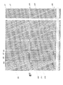
- FIG. 3 shows an example of the parity generation matrix g of the QC-LDPC code.
- each element in the (i + 1) -th row takes a value obtained by shifting each element in the i-th row to the right by 1 bit (one column) (i is a natural number).
- each element in the (i + 1) th row takes a value obtained by shifting each element in the i-th row to the right by 1 bit (i is a natural number).
- each element in the second row takes a value obtained by shifting each element in the first row to the right by 1 bit.
- each element in the second row takes a value obtained by shifting each element in the first row to the right by 1 bit.
- the sub-block matrices 201, 202, ..., 211, 212 can be said to be cyclic permutation matrices.
- the sub-block matrices 201, 202,..., 211, 212 are 27-by-27 columns.
- sub-block matrices having the same column in the parity generation matrix g are related to each other. For example, when the sub-block matrix 201 is compared with the sub-block matrix 211 having the same column as the sub-block matrix 201, the i-th row element of the sub-block matrix 211 is the (i + 1) -th row element of the sub-block matrix 201. And the second bit is different (i is a natural number).
- the i-th element of the sub-block matrix 212 is the (i + 1) -th row of the sub-block matrix 201. (I is a natural number).
- sub-block matrix of 27 rows and 27 columns is viewed vertically, for example, when the sub-block matrix 201 and the sub-block matrix 211 are viewed, as described above, these sub-block matrices are related. However, they are not necessarily the same matrix.
- the parity generation matrix g is characterized in that the elements “0” are continuously arranged. Therefore, as can be seen from FIG. 4 showing the same parity generation matrix g as in FIG. 3, a matrix 221 in which all elements constituting the matrix are “0” can be secured in the sub-block matrix 202.
- a matrix in which all elements constituting the matrix are all “0” is referred to as a zero matrix.
- a zero matrix 222 starting from the same column as the zero matrix 221 and having the same number of columns as the zero matrix 221 can be secured.
- the parity generation matrix of the QC-LDPC code includes a zero matrix and is characterized in that there are many zero matrices starting from the same column of the parity generation matrix.
- the present inventors paid attention to this feature of the parity generation matrix g of the QC-LDPC code. That is, attention is paid to the fact that if “0” is arranged as an information bit in a column other than the zero matrix of m rows and n columns, all m parity bits to be generated become zero. Further, sub-block matrices having the same column in the parity generation matrix g are related to the arrangement of elements, and the parity generation matrix g of the QC-LDPC code includes a large number of zero matrices starting from the same column. It has been noted that by arranging “0” as an information bit in a column other than the zero matrix, many parity bits that are all zero are generated.
- the information bits that need to be transmitted are zero matrix.
- m parity bits having a value of “0” are generated. These parity bits are always “0” regardless of the information bits that need to be transmitted.
- the transmitting side since the receiving side knows the position of m parity bits whose value is always “0” from the position of the zero matrix, the transmitting side must always transmit m parity bits whose value is “0”. At least, the receiving side can decode all data. In addition, the receiving side can set m parity bits whose values are always “0” as bits that are not transmitted by the transmitting apparatus, that is, reduce them as redundant bits.
- the zero matrix 221 in FIG. 4 is a 7 ⁇ 12 matrix, and information bits corresponding to the columns of the zero matrix 221 are x36 to x47. Therefore, when information bits that need to be transmitted are arranged in x36 to x47 and encoding is performed with information bits “0” other than x36 to x47, p1 to p7 are related to the values of x36 to x47. It is always “0”.
- the transmission apparatus does not transmit the parity bits p1 to p54 generated by the parity generation matrix g and whose values are always “0”. For this reason, if the transmission apparatus does not transmit the parity bits p1 to p54 generated by the parity generation matrix g and whose values are always “0”, the bit that the transmission apparatus needs to transmit is x36. Only x47, p8 to p27, and p35 to p54 can be used. In the above description, the description has been made by paying attention to p1 to p54 as an example, but the number of parity bits transmitted by the transmission apparatus can be reduced by considering the same for p55 and thereafter.
- the zero matrix 221 of FIG. 4 has 7 rows and 12 columns, if the information bits that need to be transmitted are 12 bits or less, the information bits that need to be transmitted may be arranged in the columns of the zero matrix 221. .
- the information bits that need to be transmitted are arranged in the columns of the zero matrices 231, 232. Just do it.
- the parity generation matrix g includes zero matrixes 221, 222. There are many zero matrices such as matrices 231 and 232.
- the zero matrices 231 and 232 are 7 rows and 7 columns, and even when information bits that need to be transmitted are arranged in x71 to x77, p1 to p7 and p28 to p34 are all “0”. Therefore, the transmission apparatus does not have to transmit p1 to p7 and p28 to p34, as in the case of using the zero matrices 221 and 222.
- FIG. 5 shows only a part of the parity generation matrix g of the QC-LDPC code.
- the parity generation matrix g of the QC-LDPC code includes a plurality of zero matrices starting from the same column of the parity generation matrix g and having the same number of columns.
- An information bit that needs to be transmitted is arranged in a matrix column, and “0” is arranged as a virtual bit in a column other than the zero matrix.
- parity bits having a value “0” by the same number as the number of rows of the zero matrix are generated.
- the transmitting apparatus and the receiving apparatus share the position of the zero matrix with respect to the parity generation matrix g, “0” is set on the receiving side without actually transmitting the parity bit corresponding to the row of the zero matrix.
- the encoded data encoded by the parity generation matrix g can be decoded. For this reason, the transmission apparatus can reduce the number of parity bits that need to be transmitted, and improve the transmission efficiency.
- the zero matrix may be one row and one column. That is, if there are a plurality of zero matrices of one row and one column in the same row and there are rows in which the elements in the same column as the plurality of zero matrices are zero, the number of rows in which the elements are zero in the same column is always “0”. A parity bit of “is generated.
- the transmitting apparatus inserts zeros into information bits, and generates parity bits by performing matrix operations on the information bits and zeros and the parity generation matrix of the QC-LDPC code, and the position where the information bits are arranged and the parity generation Based on the matrix, it is necessary to delete the parity bits whose values are always zero, output the deleted parity sequence, and transmit the deleted parity sequence. It is possible to reduce the number of parity bits and improve transmission efficiency.
- the transmitting apparatus sets a matrix having the largest number of rows among zero matrices (including a zero matrix of one row and one column) starting from the same column of the parity generation matrix g and having the same number of columns as a zero matrix to be set. By arranging “0” other than the set zero matrix columns, parity bits having a value of “0” are generated by the number of rows of the set zero matrix.
- the transmission apparatus can improve the transmission efficiency by puncturing the parity bit having a value of “0” as a bit that is not transmitted. At this time, the transmission apparatus sets a partial matrix that starts from the same column of the parity generation matrix g and is included in the parity generation matrix g among the zero matrices having the same number of columns as a zero matrix. Can be further reduced.
- the transmission apparatus sets the maximum number of bits that can be arranged as information bits that need to be transmitted as the number of columns of the zero matrix. For example, when zero matrices 221, 222,... Are set as zero matrices, the maximum number of bits in which information bits that need to be transmitted can be arranged is 12 bits.
- the transmission apparatus has a maximum number of bits that can arrange information bits that need to be transmitted is 19 bits. It becomes.
- the transmission device may set a zero matrix according to the data length (number of bits) of information bits that need to be transmitted. As described above, the zero matrix may be one row and one column, or may not be continuous.
- FIG. 6 shows a configuration example of an encoder that performs encoding using the parity generation matrix g as described above.
- the encoder 100 in FIG. 6 includes a zero matrix setting unit 110, an arrangement unit 120, an encoding unit 130, and a puncture unit (data reduction unit) 140.
- a puncture unit data reduction unit 140.
- the zero matrix setting unit 110 is a partial matrix of the parity generation matrix g of QC-LDPC, and sets a zero matrix whose elements are all “0”.
- the zero matrix setting method sets a zero matrix whose number of columns is equal to or greater than the header length when the data length of the information series is uniquely determined such as a header. In the following, the case where the zero matrices 221, 222,... In FIG.
- the zero matrix setting unit 110 outputs information on the position of the zero matrix in the parity generation matrix g to the arrangement unit 120 and the puncture unit (data reduction unit) 140.
- Arrangement unit 120 receives an information sequence such as a header, arranges information bits (input bits) in columns of the zero matrix based on the information of the position of the zero matrix notified from zero matrix setting unit 110, and zero matrix “0” is arranged as a virtual bit in the other columns.
- the arrangement unit 120 arranges information bits (input bits) in columns x36 to x47 of the zero matrix 221 and other than x36 to x47. "0" is placed in Arrangement unit 120 outputs the arranged bits to encoding unit 130.
- the encoding unit 130 uses the parity generation matrix g to encode the bits output from the arranging unit 120 and obtain an encoded sequence (information bits and parity bits). Encoding section 130 outputs the encoded sequence to puncture section (data reduction section) 140.
- the puncture unit (data reduction unit) 140 transmits “0” arranged in places other than x36 to x47 from the encoded sequence based on the position information of the zero matrices 221 and 222 notified from the zero matrix setting unit 110. Do not puncture (delete) as a bit.
- the puncturing unit (data reduction unit) 140 based on the position information of the zero matrices 221 and 222 notified from the zero matrix setting unit 110, the parity corresponding to the rows of the zero matrices 221 and 222 from the encoded sequence.
- Bits p1 to p7, p28 to p34,... Are punctured (deleted) as non-transmitted bits.
- the puncture unit (data reduction unit) 140 outputs encoded sequences other than bits punctured (deleted) as bits that are not transmitted from the encoded sequence as bits that need to be transmitted.
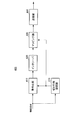
- FIG. 7 shows a configuration example of a decoder that decodes a signal transmitted from the above-described encoder.
- the decoder 300 includes a fixed log likelihood ratio insertion unit 310 and a BP (Belief Propagation) decoding unit 320.
- BP Belief Propagation
- Fixed log-likelihood ratio insertion section 310 receives a control signal indicating information on the received log-likelihood ratio calculated by a log-likelihood ratio calculation section (not shown) and the position of the zero matrix, and puts it in the position of the zero matrix. In response, a known log likelihood ratio is inserted into the received log likelihood ratio.
- the fixed log likelihood ratio insertion unit 310 receives the reception log likelihood ratios corresponding to x36 to x47 and p8 to p27, p35 to. LLR x36 to LLR x47 , LLR p8 to LLR p27 , LLR p35 to. Therefore, the fixed log likelihood ratio insertion unit 310 inserts received log likelihood ratios LLR x1 to LLR x35 , LLR x48 ..., LLR p1 to LLR p7 , LLR p28 to LLR p34 corresponding to x1 to x35 , x48,. To do.
- the fixed log likelihood ratio insertion unit 310 converts the fixed log likelihood ratio corresponding to the known bit “0” into log likelihood ratios LLR x1 to LLR x35 , LLR x48 of x1 to x35 , x48. ..., LLR p1 to LLR p7 , LLR p28 to LLR p34 ... are inserted.
- the reception log likelihood ratio surrounded by a dotted circle represents the reception log likelihood ratio inserted by the fixed log likelihood ratio insertion unit 310.
- Fixed log likelihood ratio insertion section 310 outputs the log likelihood ratio after insertion to BP decoding section 320.
- the BP decoding unit 320 performs decoding using, for example, sum-product decoding, min-sum decoding, Normalized BP decoding, offset BP decoding described in Non-Patent Document 5 to Non-Patent Document 7.
- the configuration of the communication device # 1 having the encoder configured as described above and the signal transmitted from the communication device # 1 having the decoder configured as described above are received.
- the configuration of the communication device # 2 will be described.
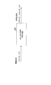
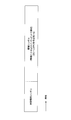
- FIG. 8 shows a frame configuration example of the modulation signal transmitted by the communication apparatus # 1.
- the control information symbol is a symbol for transmitting control information such as a modulation scheme, an error correction code used, a coding rate, a transmission method, and a data length to a communication partner (communication device # 2).
- the information symbol is a symbol for transmitting information bits and parity bits obtained by QC-LDPC encoding.
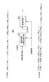
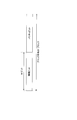
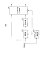
- FIG. 9 shows a configuration example of the communication device # 1.
- encoding section 410 inputs an information sequence and outputs the encoded sequence to interleaver 420.
- the encoding unit 410 is configured by the encoder 100 of FIG.
- the interleaver 420 receives the encoded sequence and performs interleaving to obtain interleaved data. Note that the interleaver 420 may not be provided depending on the type of code.
- the mapping unit 430 receives the interleaved data, and obtains a baseband signal by performing modulation such as QPSK (Quadrature Shift Keying) and 16QAM (Quadrature Amplitude Modulation).
- modulation such as QPSK (Quadrature Shift Keying) and 16QAM (Quadrature Amplitude Modulation).
- the transmitting unit 440 receives a baseband signal, obtains a modulated signal by performing predetermined signal processing such as orthogonal modulation and frequency conversion, and transmits the modulated signal.
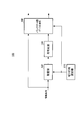
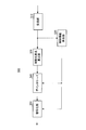
- FIG. 10 shows a configuration example of the communication device # 2.
- receiving section 510 receives a received signal and obtains a baseband signal by performing predetermined radio processing such as frequency conversion.
- Receiving section 510 outputs the baseband signal to control information detecting section 520 and log likelihood ratio calculating section 530.
- control information detection unit 520 detects information on the zero matrix, information on the interleave pattern, information on the coding rate, etc. from the baseband signal. Then, control information detection section 520 outputs interleave pattern information to deinterleaver 540, and outputs information related to the zero matrix and coding rate to decoding section 550.
- the log-likelihood ratio calculation unit 530 receives a baseband signal, calculates a log-likelihood ratio by using, for example, a method disclosed in Non-Patent Document 5, and obtains a log-likelihood ratio for each bit.
- Log likelihood ratio calculation section 530 outputs the log likelihood ratio for each bit to deinterleaver 540.
- the deinterleaver 540 receives the log-likelihood ratio for each bit and performs the deinterleaving process corresponding to the interleaver 420 to obtain the log-likelihood ratio after deinterleaving. Note that, when performing BP decoding, the decoding unit 550 can perform decoding by preparing a check matrix taking deinterleaving into consideration without providing the deinterleaver 540.
- the decoding unit 550 includes the decoder 300 shown in FIG. Decoding section 550 receives the log likelihood ratio after deinterleaving and performs reception corresponding to encoding section 410 to obtain received data.
- the zero matrix setting unit 110 sets a zero matrix that is a partial matrix of the parity generation matrix g and whose elements are all “0”.
- Arrangement unit 120 arranges input bits in columns of zero matrix and arranges “0” in columns other than zero matrix.
- the encoding unit 130 performs encoding using the parity generation matrix g to obtain parity bits.
- the puncturing unit (data reduction unit) 140 punctures (deletes) “0” arranged in a column other than the zero matrix as a bit not to be transmitted based on the information on the position of the zero matrix notified from the zero matrix setting unit 110. Further, among the obtained parity bits, the parity bits corresponding to the rows of the zero matrix are punctured (deleted) as non-transmitted bits.
- the encoder 100 receives information bits and generates parity bits by matrix operation of the information bits and the parity generation matrix.
- the encoder 100 forms a sub-matrix column in which all elements are zero. Information bits are arranged at corresponding positions, zeros are arranged at positions corresponding to columns other than the submatrix whose elements are all zero, and a matrix operation is performed between the arranged information bits and zeros and the parity generation matrix.
- the encoder 100 generates a parity sequence, deletes the parity bit whose value is always zero from the parity sequence, and outputs the deleted parity sequence.
- the encoder 100 inserts zeros into information bits, generates parity bits by matrix operation of the information bits and zeros, and a parity generation matrix of QC-LDPC, and a position and parity generation matrix where zeros are inserted. Based on the above, the parity bits whose value is always zero are deleted from the parity bits, and the deleted parity sequence is output.
- the transmission unit 440 transmits the input bits and the parity bits other than the parity bits corresponding to the zero matrix rows among the parity bits. Even if the parity bit corresponding to is not transmitted to the receiving side, decoding is performed on the receiving side by inserting a fixed log likelihood ratio known as the log likelihood ratio of the parity bit corresponding to the row of the zero matrix. Therefore, the number of parity bits to be transmitted can be reduced and the transmission efficiency can be improved.
- the information bits that need to be transmitted are not limited to headers that include control information or the like, but may be payload data (symbols for information transmission) or the like.
- the present invention can be applied if the number of information bits that need to be transmitted is smaller than the number of columns of the zero matrix included in the QC-LDPC code.
- the zero matrix setting unit 110 can set an optimal zero matrix in advance according to the header length.
- the data length of information bits that need to be transmitted varies depending on the size of the content information or the like.
- the present invention can also be applied to the case where the data length of information bits that need to be transmitted varies, for example, as payload data.
- the data length of information bits that need to be transmitted fluctuates will be described.
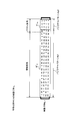
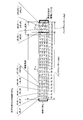
- FIG. 11 shows a configuration example of one block when the QC-LDPC code is used.
- the QC-LDPC code is a block code.
- one block includes information bits and parity bits.
- the number of information bits in one block is M bits.
- FIG. 12 shows a configuration example of the encoder according to the present embodiment.
- the encoder 100a in FIG. 12 includes a zero matrix setting unit 110a and an arrangement unit 120a in place of the zero matrix setting unit 110 and the arrangement unit 120 with respect to the encoder 100 in FIG.
- a case where an N-bit information sequence is input to the encoder 100a will be described as an example.
- the zero matrix setting unit 110a sets a zero matrix according to the data length N of information bits (input bits) input as an information series. Specifically, the zero matrix setting unit 110a first counts the data length N of information bits (input bits). Then, the zero matrix setting unit 110a divides the data length N by the information bit length M per block of the QC-LDPC code to calculate the quotient ⁇ and the remainder ⁇ .
- the arrangement unit 120a stores information in the information bit area of ⁇ blocks. It is necessary to arrange bits (input bits) and to arrange ⁇ -bit information bits (input bits) in the information bit area of one block (special block). That is, arrangement section 120a arranges information bits in all columns of parity generation matrix g of the QC-LDPC code in ⁇ blocks, and in special blocks, as described in Embodiment 1, zero matrix It is necessary to arrange information bits (input bits) in this column.
- the zero matrix setting unit 110a responds to the data length ⁇ of information bits (input bits) that need to be transmitted in a special block. To set the zero matrix. At this time, the zero matrix setting unit 110a switches the set zero matrix according to the value of the data length ⁇ . Specifically, the zero matrix setting unit 110a switches the zero matrix to be set according to the comparison result between the remainder ⁇ and a predetermined threshold. As described above, in the encoder 100a, the maximum number of bits that can be arranged as information bits that need to be transmitted varies depending on the zero matrix.
- the special block is arranged last in time, but the arrangement position is not limited to this.
- FIG. 14 shows an example in which the zero matrix setting unit 110a has two threshold values a1 and a2, and switches the zero matrix according to the comparison result between the data length ⁇ and the two threshold values. Since the number of parity bits that can be punctured (reduced) as non-transmitted bits is the same as the number of rows in the zero matrix, switching the zero matrix in other words switches the method for reducing the parity bits to be transmitted.
- the parity bit to be transmitted is reduced by the zero matrix # 1 (reduction method # 1).
- the zero matrix setting unit 110a sets the zero matrices 221, 222,... As the zero matrix.
- the arrangement unit 120a adds 2 bits of “0” to 10-bit information to make 12 bits.
- the placement unit 120a assigns these 12 bits to x36 to x47, and assigns “0” to x1 to x35 and x48 to.
- the parity bits p1 to p7, p28 to p34,... are always “0” regardless of the values of x36 to x47.
- the puncture unit (data reduction unit) 140 punctures the parity bits p1 to p7 and p28 to p34 that are always “0” as non-transmitted bits, thereby improving the transmission efficiency without degrading the decoding characteristics. be able to.
- the puncture unit 140 punctures x46 and x47, so that the transmission sequence is x36 to x45, and the parity p8 to p27, p35 to p54, and so on, and the transmission efficiency can be further improved.
- the parity bits to be transmitted are reduced by the zero matrix # 2 (reduction method # 2).
- the zero matrix setting unit 110a sets the zero matrices 231, 232,... As the zero matrix in addition to the zero matrices 221, 222,.
- the arrangement unit 120a adds 4 bits of “0” to 15 bits of information to make 19 bits.
- the placement unit 120a assigns the 19 bits to x36 to x47 and x71 to x77, and assigns “0” to x1 to x35, x48 to x71, and x78 to.
- the parity bits p1 to p7, p28 to p34,... are always “0” regardless of the values of x36 to x47.
- the puncture unit (data reduction unit) 140 punctures the parity bits p1 to p7 and p28 to p34 that are always “0” as non-transmitted bits, thereby improving the transmission efficiency without degrading the decoding characteristics. be able to.
- the transmission device can further improve the transmission efficiency.
- the puncture unit (data reduction unit) 140 punctures x74 to x77, so that the transmission sequence is x36 to x45, x71 to x73. , P8 to p27, p35 to p54,..., And the transmission device can further improve the transmission efficiency.
- the zero matrix setting unit 110a sets a zero matrix according to the data length ⁇ of information bits (input bits) that need to be transmitted in a special block. Then, the zero matrix setting unit 110a notifies the arrangement unit 120a and the puncture unit (data reduction unit) 140 of the information on the position of the zero matrix in the parity generation matrix g.
- the zero matrix setting unit 110a does not set the zero matrix and does not reduce the parity bit when a2 ⁇ ⁇ M ⁇ 1. Therefore, when a2 ⁇ ⁇ M ⁇ 1, the zero matrix setting unit 110a notifies the puncture unit (data reduction unit) 140 not to puncture the parity bits.
- the zero matrix setting unit 110a is a partial matrix of the parity generation matrix g, and a zero matrix having all the elements “0” is converted into a data length N of information bits (input bits). It was made to set according to. In this way, the transmission device can reliably transmit information bits (input bits) while reducing the number of parity bits that need to be transmitted.
- the zero matrix setting unit 110a may further have a threshold value and be divided into Z cases.
- a transmitting apparatus including an encoder may first notify the receiving apparatus of information on the number of bits of data to be transmitted. At this time, the receiving apparatus needs to include an arithmetic unit for obtaining ⁇ .
- FIG. 15 shows a configuration example of the encoder according to the present embodiment.
- the encoder 600 in FIG. 15 includes an encoding unit 610, a puncture pattern setting unit 620, and a puncture unit (data reduction unit) 630.
- the encoding unit 610 encodes the information sequence using the QC-LDPC parity generation matrix g.
- the puncture pattern setting unit 620 searches for and sets a puncture pattern using the fact that the check matrix H of the QC-LDPC code is configured with a sub-block matrix as a basic unit. A method for searching for a puncture pattern will be described later.
- the puncture pattern setting unit 620 outputs the set puncture pattern information to the puncture unit (data reduction unit) 630.
- the puncturing unit (data reduction unit) 630 punctures information bits or parity bits as non-transmitted bits in the encoded sequence output from the encoding unit 610 according to the puncture pattern notified from the puncture pattern setting unit 620 ( Set as a bit not to be transmitted).
- the puncture pattern is searched for using the fact that the check matrix H of the QC-LDPC code is configured with a sub-block matrix as a basic unit.
- the puncture pattern setting unit 620 When searching for a puncture pattern, the puncture pattern setting unit 620 first determines the period of the puncture pattern. For example, when K bits are selected from 20 bits that are not transmitted (puncture bits), the period of the puncture pattern is 20 bits. At this time, the number of non-transmitted bits (puncture bits) included in 20 bits of the puncture pattern period is K, and is always constant.
- ⁇ q ⁇ p ⁇ 1) is 1, and the other is a cyclic permutation matrix such that “0” is an integer multiple of the number of columns L) or a divisor of the number of columns L (see Equation (1)) .
- an integer multiple of 27 or a divisor of 27 is set as the period of the puncture pattern. It is proposed to set K bits not to be transmitted (puncture bits).
- the puncture pattern setting unit 620 pays attention to the fact that the sub-block matrix constituting the check matrix H of the QC-LDPC code is regular, and is an integer multiple of the number of columns of the sub-block matrix or the number of columns.
- a puncture pattern with good characteristics can be reliably found in a relatively short time.
- a predetermined SNR Signal-to-Noise power ratio
- an error rate is obtained for each puncture pattern, and the error rate is lowered. Find a puncture pattern.
- the transmission apparatus can improve transmission efficiency while maintaining good reception quality by puncturing the encoded sequence using the puncture pattern searched in this way. That is, the important point in the configuration of FIG. 15 is that the puncturing unit (data reduction unit) 630 uses the encoded sequence as an integer multiple of the number of columns of the sub-block matrix constituting the QC-LDPC code check matrix H, or Puncture is performed in units of divisors of numbers.
- the puncture unit (data reduction unit) 630 sets the period of the puncture pattern as the number L of columns of the subblock matrix, and sets the number of bits (puncture bits) not transmitted for each number of columns L of the subblock matrix as K. The case where it is assumed to be constant will be described. In this case, puncturing section (data reduction section) 630 switches the puncturing pattern for each integer multiple of the number of columns of the sub-block matrix that constitutes QC-LDPC code parity check matrix H.
- the puncture pattern switching method will be specifically described with reference to FIGS. 16A to 16C.
- FIG. 16A shows a state in which the puncture pattern is switched for each number of columns of the sub-block matrix (one times the number of columns) with respect to the parity check matrix H of FIG.
- the check matrix H in FIG. 3 is composed of 27 columns of sub-block matrices, so the puncture unit (data reduction unit) 630 does not transmit bits (punctures) using puncture pattern # 0 for x1 to x27. K bits) are selected.
- the puncture unit (data reduction unit) 630 uses puncture pattern # 1 for x28 to x54 and selects K bits (puncture bits) not to be transmitted.
- the puncture unit (data reduction unit) 630 selects K bits (puncture bits) that are not transmitted using puncture pattern # 23 for p622 to p648.
- FIG. 16B shows a state in which the puncture pattern is switched every two times the number of columns of the sub-block matrix with respect to the check matrix H of FIG. 3 is composed of a 27-column sub-block matrix, puncture section (data reduction section) 630 transmits puncture pattern # 0 to x1 to x27 and x28 to x54. Select K bits not to be used (puncture bits).
- the puncture unit (data reduction unit) 630 uses the puncture pattern # 1 for x55 to x81 and x82 to x108, and selects K bits not to be transmitted (puncture bits).
- the puncture unit (data reduction unit) 630 selects K bits (puncture bits) that are not transmitted using puncture pattern # 2 for x109 to x135 and x136 to x162.
- FIG. 16C shows a state in which the puncture pattern is switched every 9 columns with respect to the parity check matrix H of FIG. 3 using a divisor of 9 columns of the sub-block matrix as a basic period.
- puncturing section (data reduction section) 630 selects K bits (puncture bits) that are not transmitted using puncture pattern # 0 for x1 to x9.
- the puncture unit (data reduction unit) 630 selects K bits (puncture bits) that are not transmitted using puncture pattern # 1 for x10 to x18.
- the puncture unit (data reduction unit) 630 selects K bits (puncture bits) that are not transmitted using the puncture pattern # 2 for x19 to x27.
- the puncture unit (data reduction unit) 630 selects K bits (puncture bits) that are not transmitted using puncture pattern # 3 for x28 to x36.
- the puncture unit (data reduction unit) 630 selects K bits (puncture bits) that are not transmitted using puncture pattern # 4 for x37 to x45.
- the puncture unit (data reduction unit) 630 selects K bits (puncture bits) that are not transmitted using puncture pattern # 5 for x46 to x54.
- the puncture unit (data reduction unit) 630 selects K bits (puncture bits) that are not transmitted using the puncture pattern # 69 for x622 to x630.
- the puncture unit (data reduction unit) 630 selects K bits (puncture bits) that are not transmitted using the puncture pattern # 70 for x631 to x639.
- the puncture unit (data reduction unit) 630 selects K bits (puncture bits) that are not transmitted using puncture pattern # 71 for x640 to x648.
- the puncture unit (data reduction unit) 630 defines a puncture pattern # S0 composed of puncture patterns # 0 to # 2, and bits (puncture bits) that are not transmitted using puncture pattern # S0 in x1 to x27 You may make it select 3K pieces.
- puncture section (data reduction section) 630 defines puncture pattern # S1 composed of puncture patterns # 3 to # 5, and bits (puncture bits) that are not transmitted using puncture pattern # S1 in x28 to x54 ) May be selected.
- puncture section (data reduction section) 630 defines puncture pattern # S23 composed of puncture patterns # 69 to # 71, and bits that are not transmitted using puncture pattern # S23 (puncture bits) in x622 to x648 ) May be selected.
- puncturing with a divisor of the number of columns of the sub-block matrix as a basic period is equivalent to puncturing with the number of columns of the sub-block matrix constituting the parity check matrix H of the QC-LDPC code as a unit (period).
- puncture pattern setting section 620 puncture pattern is set to an integer multiple of the number of columns of the sub-block matrix constituting parity check matrix H of the QC-LDPC code, or every divisor of the number of columns.
- the puncture unit (data reduction unit) 630 switches the puncture pattern every integer multiple of the number of columns of the sub-block matrix constituting the parity check matrix of the QC-LDPC code, or every divisor of the number of columns.
- “puncture pattern # 0”, “puncture pattern # 1”,..., “Puncture pattern # 23” may be the same puncture pattern.
- “puncture pattern # 0”, “puncture pattern # 1”, “puncture pattern # 2”,... May be the same puncture pattern.
- Puncture pattern # 0 may be the same puncture pattern.
- the unit of the puncture pattern may be an integer multiple of the number of columns of the sub-block matrix constituting the parity check matrix of the QC-LDPC code or a divisor of the number of columns.
- Embodiment 4 an example of an encoding method when the encoding method described in Embodiments 1 and 2 is used for control information will be described.
- QC-LDPC code of Coding ⁇ rate (R) 1/2
- LDPC code information block length (bits) 168
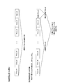
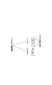
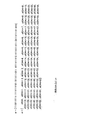
- FIG. 17 shows a case where 200-bit control information is divided into 168 bits and 32 bits, 168 bits are arranged in block # 1, and 32 bits are arranged in block # 2.
- block # 2 only 32 bits of control information are arranged for a block length of 168 bits.
- a block whose bit that needs to be transmitted is shorter than the block length, such as block # 2 is the special block described in the second embodiment. Therefore, as in Embodiment 2, in block # 2, “0” is arranged as a virtual bit as an information bit and encoded. As a result, the reception quality varies between the block # 1 and the block # 2, and the reception quality of the 200-bit control information eventually depends on the block with the poor reception quality.
- 200-bit control information is arranged as evenly as possible in the two blocks # 1 and # 2, and the encoding described in the first embodiment is performed for each block. I do. Specifically, when the control information is 200 bits, the control information is arranged by 100 bits in both block # 1 and block # 2.
- both the block # 1 and the block # 2 become special blocks, so that “0” is arranged as a virtual bit in both the block # 1 and the block # 2, and the code in the first embodiment It is encoded by the encoding method. As a result, the reception quality of block # 1 and block # 2 is equalized, and transmission to the communication partner can be performed accurately.
- control information is 201 bits
- 101 bits of control information are arranged in block # 1
- 100 bits of control information are arranged in block # 2.
- the difference between the number of control information bits in block # 1 and the number of control information bits in block # 2 is at most one bit.
- the transmission apparatus can equalize the reception quality between each block by arranging the information that needs to be transmitted in the two blocks as evenly as possible, so that the control information can be reliably transmitted to the communication partner. Can be transmitted.
- control information is arranged as evenly as possible in a plurality of blocks.
- the transmission apparatus reliably transmits information necessary for establishing communication such as control information to the communication partner by applying the encoding method described in the first embodiment to each block after arrangement. Can do.
- the special block generation method in the present embodiment is the same as the special block generation method described in the second embodiment. That is, the transmission apparatus sets (sets as a puncture bit) a bit that does not transmit both information bits and parity bits that do not need to be transmitted.
- the check matrix H of the QC-LDPC code is defined as shown in Equation (4).
- the parity check matrix H in Equation (4) is a matrix with m rows and n columns.
- n is the code length
- P i, j is a z-by-z cyclic permutation matrix or a z-by-z zero matrix.
- the parity check matrix H of Equation (4) is expanded by a matrix H b of n b rows and m b columns.
- m z ⁇ m b
- P i, j is a set of matrices obtained by cyclically shifting a unit matrix of z rows and z columns or a unit matrix of z rows and z columns as a cyclic permutation matrix.
- Cyclic permutation matrix is a unit matrix, or, since it is a set of cyclic shifted matrix unit matrix, the matrix H b, the matrix H b and sizes are decomposed into the same matrix H bm, matrix H bm is zero It is indicated by a matrix or a matrix obtained by cyclically shifting a unit matrix.
- the zero matrix is denoted as “ ⁇ 1”.
- the unit matrix is denoted as “0”.
- the cyclic permutation matrix of the unit matrix is denoted as “p (i, j)” using the cyclic shift amount p (i, j) (> 0).
- the matrix H b can be expressed as a set of the matrix H bm marked compactly in this way.
- the matrix H b is divided into two sub-matrices H b1 and H b2 as shown in Expression (5).
- the sub-matrix H b1 is a partial matrix related to information bits
- the sub-matrix H b2 is a sub-matrix related to parity bits.
- the sub-matrix H b2 is further divided into a vector h b and a sub-matrix H ′ b2 as shown in Equation (6).
- the portion marked “1” indicates that the shift amount of the unit matrix is zero. That is, the sub-matrix H ′ b2 is replaced with a unit matrix of z rows and z columns when expanded into the matrix H b .
- Equation (7) the matrix Hb defined by equation (7) is considered.
- the parity check matrix H defined by Equation (7) can correspond to the maximum code length at each coding rate.
- Equation (7) p (f, i, j) represents the cyclic shift amount of the unit matrix, and f represents the code length index corresponding to each coding rate.
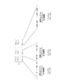
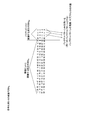
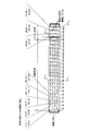
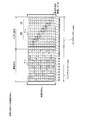
- FIG. 19A shows a QC-LDPC matrix H b with a coding rate of 1/2 shown in equation (8).
- the matrix H b with a coding rate of 1 ⁇ 2 has 12 rows of the partial matrix H b1 related to the information bits
- the partial matrix H b2 related to the parity bits has 12 columns. .
- the submatrix H b2 related to the parity bit in FIG. 19A is composed of “ ⁇ 1” and “0” except for the first row and the first column and the 12th row and the first column, and has a regular arrangement. .
- “ ⁇ 1” indicates a zero matrix
- “0” indicates a unit matrix
- “7” in the first row and the first column and the 12th row and the first column is a cyclic permutation matrix obtained by cyclically shifting the unit matrix by 7.
- the encoded sequence can be combined with the puncturing method described in the third embodiment. That is, it is more effective to puncture the encoded sequence in units of an integer multiple of the number of columns of the sub-block matrix constituting the parity check matrix H of the QC-LDPC code or a divisor of the number of columns.
- FIG. 19B and FIG. 19C with respect to the partial matrix H b2 related to the parity bit, an integer multiple of the number of columns of the sub-block matrix constituting the parity check matrix H of the QC-LDPC code or a divisor of the number of columns is used as a unit. An example of performing puncturing is shown.
- FIG. 19B shows another application example of the QC-LDPC matrix H b and the puncture pattern of coding rate 1/2 shown in Equation (8).
- FIG. 19B shows an example in which the puncture pan turn period is set to an integer multiple (2 times) the number of columns of the sub-block matrix constituting the parity check matrix of the QC-LDPC code. Note that FIG. 19B is an example in which the same puncture pattern #B is used for a portion constituted by a unit matrix and a zero matrix.
- FIG. 19C shows another application example of the QC-LDPC matrix H b and the puncture pattern of coding rate 1/2 shown in Equation (8).
- FIG. 19C shows an example in which a puncture pattern is generated for each half of the number of columns of the sub-block matrix constituting the parity check matrix of the QC-LDPC code. Note that FIG. 19C is an example in which the same puncture pattern is used for the portion constituted by the unit matrix and the zero matrix.
- FIG. 19C shows a check matrix H composed of 100-row 100-column sub-block matrix, with 50 columns with a divisor of 50 columns, which is 1/2 of the number of columns of the sub-block matrix, as a basic period It shows how the puncture pattern is switched every time.
- the puncture unit (data reduction unit) 630 selects bits (puncture bits) that are not transmitted using puncture pattern # 1 for p100 to p149.
- the puncture unit (data reduction unit) 630 selects bits (puncture bits) that are not transmitted using puncture pattern # 2 for p150 to p199.
- the puncture unit (data reduction unit) 630 selects bits not to be transmitted (puncture bits) using puncture pattern # 3 for p200 to p249.
- the puncture unit (data reduction unit) 630 selects bits (puncture bits) that are not transmitted using puncture pattern # 4 for p250 to p299.
- the puncture unit (data reduction unit) 630 selects bits not to be transmitted (puncture bits) using puncture pattern # 21 for p1100 to p1149.
- the puncture unit (data reduction unit) 630 selects bits not to be transmitted (puncture bits) using puncture pattern # 22 for p1150 to p1199.
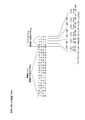
- FIG. 20A shows a QC-LDPC matrix H b with a coding rate of 5/6 shown in equation (9).
- the parity check matrix H b having a coding rate of 5/6 has four rows in the sub matrix H b1 related to the information bits, and thus the sub matrix H b2 related to the parity bits has four columns. Become.
- the submatrix H b2 related to the parity bit in FIG. 20A is composed of “ ⁇ 1” and “0” except for the first row and the first column and the fourth row and the first column, and has a regular arrangement.
- “80” in the first row and first column and the fourth row and first column is a cyclic permutation matrix obtained by cyclically shifting the unit matrix by 80.
- the part constituted by the unit matrix and the zero matrix may use the same puncture pattern.
- the effect on reception quality is low.
- the reception apparatus can obtain good reception characteristics even if the same puncture pattern #A is used for the columns of the part composed of the unit matrix and the zero matrix (see FIG. 20A). It should be noted that columns that do not correspond to the portion constituted by the unit matrix and the zero matrix are set as different puncture patterns, but some of them may be the same puncture pattern.
- FIG. 20B shows another application example of the QC-LDPC matrix H b and the puncture pattern of the coding rate 5/6 shown in Equation (9).
- FIG. 20B shows an example in which the puncture pattern period is set to an integer multiple (three times) the number of columns of the sub-block matrix constituting the parity check matrix of the QC-LDPC code.
- FIG. 20C shows another application example of the QC-LDPC matrix H b and the puncture pattern of the coding rate 5/6 shown in Equation (9).
- FIG. 20C shows an example in which a puncture pattern is generated for each half of the number of columns of the sub-block matrix constituting the QC-LDPC code check matrix. Similar to FIG. 20B, FIG. 20C is an example in which the same puncture pattern is used for the portion constituted by the unit matrix and the zero matrix.
- FIG. 20C shows a check matrix H composed of 100-row 100-column sub-block matrix, with 50 columns with a divisor of 50 columns, which is 1/2 of the number of columns of the sub-block matrix, as a basic period It shows how the puncture pattern is switched every time.
- the puncture unit (data reduction unit) 630 selects bits (puncture bits) that are not transmitted using puncture pattern # 1 for p100 to p149.
- the puncture unit (data reduction unit) 630 selects bits (puncture bits) that are not transmitted using puncture pattern # 2 for p150 to p199.
- the puncture unit (data reduction unit) 630 selects bits not to be transmitted (puncture bits) using puncture pattern # 3 for p200 to p249.
- the puncture unit (data reduction unit) 630 selects bits (puncture bits) that are not transmitted using puncture pattern # 4 for p250 to p299.
- the puncture unit (data reduction unit) 630 selects bits (puncture bits) that are not transmitted using puncture pattern # 5 for p300 to p349.
- the puncture unit (data reduction unit) 630 selects bits (puncture bits) that are not transmitted using puncture pattern # 6 for p350 to p399.
- the part constituted by the unit matrix and the zero matrix sets the same puncture pattern and does not correspond to the part constituted by the unit matrix and the zero matrix. For columns, set different puncture patterns.
- the columns that do not correspond to the portion formed by the unit matrix and the zero matrix are, for example, an integer multiple of the number of columns of the sub-block matrix that constitutes the parity check matrix of the QC-LDPC code, as described in Embodiment 3.
- the puncture pattern may be switched every divisor of the number of columns.
- the pattern length of the puncture pattern is an integral multiple of the number of columns of the sub-block matrix constituting the parity check matrix of the QC-LDPC code, or the number of columns
- the same puncture pattern that is every divisor may be applied.
- Embodiment 6 An integer multiple of the number of columns of the sub-block matrix that uses the QC-LDPC code described in Embodiment 5 and constitutes the parity check matrix of the QC-LDPC code described in Embodiment 4, or a divisor of the number of columns An example is shown in which puncturing is performed in units of and the same puncture pattern is used for all.
- Embodiment 6 describes a puncture pattern for realizing a coding rate of about 0.65 by puncturing from a QC-LDPC code having a parity check matrix of equation (8) with a coding rate of 1/2.
- the size of the sub-block matrix constituting the parity check matrix of the QC-LDPC code is 350 rows and 350 columns. Therefore, Information block length (bits) of the QC-LDPC code is 4200, and LDPC codeword block length (bits) is 8400.
- the codeword of the LDPC code is expressed as follows.
- v means codeword
- x means information
- p means parity.
- v0, v1,..., Vi..., V167 are expressed as follows.
- v0 [s0, s1, ..., s48, s49]
- v1 [s50, s51, ..., s98, s99]
- ... vi [s50 * i, s50 * i + 1, ..., s50 * i + 48, s50 * i + 49]
- ... v167 [s8350, s8351, ⁇ ⁇ ⁇ , s8398, s8399]
- the present inventors have found that, when 50, which is a divisor of the number of columns of a sub-block matrix constituting a parity check matrix of a QC-LDPC code, is a puncture pattern period, good reception quality is provided. confirmed.
- Puncturing patterns that give good reception quality are as follows. (1, 8, 19, 20, 25, 28, 29, 31, 38, 40, 41)
- a puncture pattern for realizing a coding rate of about 0.95 by puncturing from a QC-LDPC code having a parity check matrix of equation (9) with a coding rate of 5/6 will be described.
- the size of the sub-block matrix constituting the QC-LDPC code check matrix is 210 rows and 210 columns. Therefore, in the QC-LDPC code, Information block length (bits) is 4200, and LDPC codeword block length (bits) is 5040.
- the codeword of the LDPC code is expressed as follows.
- v means codeword
- x means information
- p means parity.
- V0, v1,..., Vi..., V79 are expressed as follows.
- v0 [s0, s1, ..., s61, s62]
- v1 [s63, s64, ..., s124, s125], ...
- vi [s63 * i, s63 * i + 1, ..., s63 * i + 61, s63 * i + 62]
- ... v79 [s4977, s4978, ..., s5038, s5039].
- the present inventors have confirmed that good reception quality can be obtained if 63 is a period of the puncture pattern.
- Puncturing patterns that give good reception quality are as follows. (3, 18, 20, 27, 39, 50, 60)
- the period of the puncture pattern refers to the minimum period of the puncture pattern.
- the (minimum) period of the puncture pattern is 3, like the puncture table w1. That is, the period of the puncture pattern refers to the pattern length of the minimum pattern among the patterns constituting the puncture pattern.
- the puncture table w3 [010] is the same as that obtained by cyclically shifting w1, but considering the relationship between w, vi, and vi ′, it can be said that w3 and w1 are different puncture patterns. That is, when there is a puncture table wx and a puncture table wy, wx and wy are different puncture patterns even if wx is cyclically shifted (except for 0-bit cyclic shift) and becomes the same as wy.
- the period of the puncture pattern is too long, randomness occurs in the arrangement of bits (puncture pits) that are not transmitted, and the binary erasure channel approaches the model in which a random error has occurred, resulting in poor data quality at the time of reception.
- the period of the puncture pattern is too short, the arrangement of non-transmitted bits (puncture pits) is offset, so that the possibility of an appropriate puncture pattern is reduced, and the data quality at the time of reception deteriorates. For this reason, it is important to set the period of the puncture pattern to about 20 to 90.
- the puncture pattern period is set to about 20 to 90, if the puncture table w includes three or more zeros, the data quality at the time of reception becomes good (good data quality at the time of reception (decoding). The possibility of generating a puncture pattern that can be obtained is increased). If the puncture table w includes three or more zeros, the arrangement of bits not transmitted (puncture pits) is not regular and randomness is increased, so that the data quality at the time of reception is good.
- the period of the puncture pattern is set to about 20 to 90
- the puncture table w includes three or more zeros, and is an integer multiple of the number of columns of the sub-block matrix constituting the parity check matrix of the QC-LDPC code
- the divisor of the number of columns is the period of the puncture pattern, there is a high possibility that a puncture pattern capable of obtaining good data quality at the time of reception (decoding) can be generated.
- the puncture patterns other than the above are as follows.
- the size of the sub-block matrix constituting the parity check matrix of the QC-LDPC code is 80 rows and 80 columns, and the QC-LDPC code (Information block length) having the parity check matrix of equation (8) with a coding rate of 1/2.
- w [1111110110 0100111111111]
- When the coding rate is about 0.75: w [1100111111 1101111110 0111110001 1110000111]
- the size of the sub-block matrix constituting the parity check matrix of the QC-LDPC code is 180 rows, 180 columns, and a QC-LDPC code (Information block length) having a parity check matrix of Equation (8) with a coding rate of 1/2.
- For coding rate of about 0.75: w [1111110100 0001101001 1111111110]
- the sub-matrix H ′ b1 uses a puncture pattern # p1 in which the number of columns of the sub-matrix H ′ b1 is a puncture period, and the sub-matrix H ′ b2 in using the puncture patterns # p2 to the number of columns of submatrix H 'b2 and puncturing pattern period, the case of realizing a coding rate 20/21.
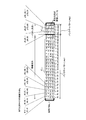
- Parity check matrix Hb in FIG. 24 is QC-LDPC parity check matrix Hb shown in Equation (9).
- the parity check matrix Hb of Equation (9) is composed of a 4 ⁇ 24 sub-block matrix.
- the size of the sub-block matrix constituting the parity check matrix of the QC-LDPC code is 48 rows and 48 columns. Therefore, in the QC-LDPC code, the information block length (bits) is 960, and the LDPC codeword block length (bits) is 1152.
- the codeword of the LDPC code is expressed as follows.
- v0, v1,..., Vi..., V23 are expressed as follows.
- v0 [s0, s1, ..., s46, s47]
- v1 [s48, s48, ..., s94, s95]
- ... vi [s48 * i, s48 * i + 1, ..., s48 * i + 46, s48 * i + 47]
- ... v23 [s1104, s1105, ..., s1150, s1151].
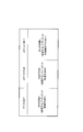
- # 0 indicates a partial matrix corresponding to x0, x1,..., X47
- # 1 indicates a partial matrix corresponding to x48, x49
- # 21 indicates a partial matrix corresponding to p48, p49,..., P95
- # 22 indicates a partial matrix corresponding to p96, p97,..., P143
- # 23 indicates p144, p145,.
- the submatrix corresponding to p191 is shown.
- the sub matrix H ′ b1 is composed of # 0 to # 20
- the sub matrix H ′ b2 is composed of # 21, # 22, and # 23.
- # 21, # 22, and # 23 are composed of a unit matrix (“0”) and a zero matrix (“ ⁇ 1”).
- the check matrix H b of the QC-LDPC code shown in Equation (9) includes a sub-matrix H ′ b2 composed of a unit matrix and a zero matrix.
- a suitable puncture pattern is determined as follows in consideration of the characteristics of the sub-matrix H ′ b2 and BP decoding.
- the logarithmic likelihood ratio of each bit is obtained by repeating the row operation and the column operation.
- the log likelihood ratio is updated.
- a bit that has not been transmitted (puncture) is treated as an erasure bit at the time of decoding, and since the initial log likelihood ratio does not exist for the erasure bit, the log likelihood ratio becomes 0. Is set. If two or more erasure bits that do not have an initial log-likelihood ratio are included in the same row, the logarithmic likelihood of the row operation alone in that row until the log-likelihood ratio of the erasure bit is updated by the column operation. The ratio is not updated. Therefore, it is preferable that the erasure bit is less than 2 bits in the same row.
- the external value is updated.
- the external value of the erasure bit is updated by the addition result of the log likelihood ratio of “1” excluding itself in the same column. Therefore, when the column weight is large, the external value of the erasure bit is updated by the addition result of a plurality of log likelihood ratios of “1” excluding itself in the same column.
- the absolute value becomes large, which makes it easy for the log-likelihood ratio to converge.
- the absolute value of the log likelihood ratio in the external value is difficult to increase, and thus the log likelihood ratio is difficult to converge. It will have properties.
- the column weight of the erasure bit is 3 or more.
- the number of erasure bits is less than 2 bits in the same row, and from the viewpoint of column operation, 2)
- the column weight is preferably 3 or more.
- a puncture pattern is set in consideration of the above 1) and 2).
- an example in which an encoded sequence is punctured in units of the number of columns of the sub-block matrix will be described.
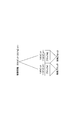
- the parity check matrix H b of Equation (9) is expressed with the sub-block matrix as one unit, in the sub-matrix H ′ b2 , the unit matrix (“0”) is in the i-th row and the (i + 1) -th row.
- a zero matrix (“ ⁇ 1”) is arranged in rows other than i columns and (i + 1) rows in j columns, and unit matrices are arranged in (i + 1) rows and (i + 2) rows in (j + 1) columns.
- a unit matrix (“0”) is arranged in the first and second rows of 22 columns, and the rows other than the first and second rows of 22 columns (3 and 4 rows).
- a unit matrix (“0”) is arranged with 2 rows and 3 rows of 23 columns, and rows other than 2 rows and 3 rows of 23 columns
- a zero matrix (“ ⁇ 1”) is arranged in 1 row and 4 rows
- a unit matrix (“0”) is arranged in 3 rows and 4 rows of 24 columns, and 3 rows and 4 rows of 24 columns.
- a zero matrix (“ ⁇ 1”) is arranged in rows other than the rows (1 row and 2 rows). Therefore, the unit matrix (“0”) is arranged adjacent to the same row as shown in the portion surrounded by the square frame in the sub-matrix H ′ b2 in FIG.
- the erasure bit is only one bit for each row of the unit matrix.
- the unit matrix is arranged adjacent to the same row and the bit corresponding to the column including the unit matrix is not transmitted (puncture bit)
- the erasure bit is 2 bits in each row.
- the unit matrix when the unit matrix is arranged adjacent to the same row as in the second row unit matrix (“0”) of 22 columns and 23 columns in FIG. 24, these two unit matrices are arranged. Assuming that the bit corresponding to the column including the bit is not transmitted (puncture bit), the erasure bit is 1 bit in each row of the unit matrix (“0”) in the 2nd row of 22 columns, and the 2nd row in the 23rd column In each row of the unit matrix (“0”), the erasure bit is 1 bit. In each unit matrix, the erasure bit is 1 bit in each row, but these unit matrices are arranged adjacent to the same row. In the same row where the unit matrix is arranged, the erasure bit is 2 bits.
- the number of erasure bits is less than 2 bits. Therefore, in order to avoid the loss of 2 bits, a puncture pattern in which bits corresponding to columns # 21 and # 23 that are not arranged adjacent to the same row in the unit matrix are not transmitted (puncture bits) is used. We will use it. That is, when the bit corresponding to the # 21 column is not transmitted (puncture bit), the bit corresponding to the # 23 column separated by the number of columns of one subblock matrix is not transmitted (puncture bit). .
- the encoded sequence is punctured with the number of columns of the sub-block matrix as a unit
- the puncturing interval is 1 unit (the number of columns of one sub-block matrix) or more
- the unit matrix or the zero matrix can be changed.
- the number of bits lost due to puncturing is only 1 bit in each row, and the loss of 2 bits can be avoided, so that the degradation of reception quality can be avoided.
- the column weight is 3 or more, and therefore the bit (puncture) that does not transmit the bit corresponding to the column of the sub-matrix H ′ b1 Bit) is updated so that the absolute value of the log-likelihood ratio of the external value is increased by the column operation, and the likelihood of the log-likelihood ratio of the erasure bit is increased, and the reception characteristic is improved.
- FIG. 25 shows an example in which, in addition to # 21 and # 23, the bit corresponding to the # 4 column is a bit (puncture bit) that is not transmitted.
- # 4 since the zero matrix (“ ⁇ 1”) is arranged in the row where the unit matrix (“0”) is arranged in # 23, it corresponds to the columns of # 4, # 21, and # 23.
- the bit is not transmitted (puncture bit)
- the lost bit of the row is maintained at 1 bit, so that degradation of reception quality can be suppressed.
- a puncture table (puncture pattern) w in a case where bits corresponding to columns # 4, # 21, and # 23 are not transmitted (puncture bits) is expressed as shown in Expression (10).
- 0 included in the puncture table w means a bit (puncture bit) that is not transmitted. That is, in the example shown in FIG. 25, bits corresponding to columns # 4, # 21, and # 23, that is, x192, x193,..., X238, x239, p48, p49,..., P94, p95, p144, p145, ..., p190, p191 are punctured.
- the unit matrix (“0”) is arranged in the i row and the (i + 1) row of the j column.
- the parity check matrix H b the b1 'sub-matrix H other than b2' the sub-matrix H, by a bit (puncture bits) that does not transmit the bit column degree corresponding to three or more columns, column Since the update is performed so that the absolute value of the log likelihood ratio of the external value in the calculation is increased, it is possible to suppress the deterioration of the reception quality.
- the sub-matrix H 'b2, # 21 and # 23 bits bits corresponding to the column does not send the (puncture bits ), For example, as in # 4, a bit (puncture bit) that does not transmit a bit corresponding to a column of a zero matrix arranged in any row of the unit matrix included in # 21 or # 23 ).
- the bits corresponding to the columns of # 4, # 21, and # 23 are not transmitted bits (puncture bits)
- the erasure bit of the row where the zero matrix is arranged in # 4 is suppressed to 1 bit. Therefore, it is possible to suppress degradation of reception quality.
- the suitable puncture pattern for realizing the coding rate 20/21 by puncturing from the QC-LDPC code having the parity check matrix of the equation (9) of the coding rate 5/6 has been described.
- a suitable puncture table (puncture pattern) w for realizing the rate 20/21 is expressed by, for example, Expressions (11-1) to (11-3).
- the encoded sequence is punctured using the number of columns of the sub-block matrix as a unit has been described, but the number of columns of the sub-block matrix is spaced by one unit (number of columns of the sub-block matrix) or more. It is also possible to set a candidate for a bit (puncture bit) not to be transmitted in units of and to determine a bit (puncture bit) not to be transmitted from this candidate. In this case, candidates for bits not to be transmitted (puncture bits) are set with the number of columns of the sub-block matrix as a unit, and as described above, bits corresponding to columns not including the unit matrix adjacent to the same row To do.
- bits corresponding to columns # 4, # 21, and # 23 are set as candidates for bits (puncture bits) that are not transmitted, and x192, corresponding to columns # 4, # 21, and # 23. .., x238, x239, p48, p49,..., p94, p95, p144, p145,..., p190, p191. It may be determined.
- a suitable puncture table (puncture pattern) w for realizing 16/18 is expressed as in Expression (12).
- a suitable puncture table (puncture pattern) w for realizing the rate 16/18 is expressed as in Expression (13).
- v [p0, p1,..., P190, p191, x0, x1,..., X958, x959]).
- P97,..., P142, p143 may be bits that are not transmitted (puncture bits).
- the unit matrix (“0”) is arranged in the j row i row and the (i + 1) row, and the row other than the j row i row and the (i + 1) row is arranged.
- Has a zero matrix (“ ⁇ 1”) and a unit matrix (“0”) is arranged in (i + 1) and (i + 2) rows of (j + 1) columns, and (i + 1) in (j + 1) columns.
- J q, q + 1, q + 2,..., Q + s ⁇ 1, q + s (where s is 1).
- the case where the unit matrix is arranged adjacent to the same row has been described.
- the cyclic shift matrix of the unit matrix is arranged adjacent to the same row.
- a suitable puncture pattern can be obtained using the puncture pattern generation method described above.
- the cyclic shift matrix of the unit matrix is arranged adjacent to the same row in the sub-matrix H′b2 , the configuration of the encoder may be complicated.
- a suitable puncture pattern can be set for the QC-LDPC code with a coding rate of 1/2 in Equation (8) by the same method.
- a case where the coding rate is 1/2 will be described with reference to FIG.
- FIG. 27 is a parity check matrix Hb of the QC-LDPC code with a coding rate of 1/2 in Equation (8).
- the parity check matrix Hb of Equation (8) is configured from a 12 ⁇ 24 subblock matrix.
- the sub-matrix H ′ b2 includes a unit matrix and a zero matrix, and the sub-matrix H ′ b1 is other than the sub-matrix H ′ b2 .
- # 0 to # 23 indicate sub-matrices corresponding to each column
- sub-matrix H ′ b1 is composed of # 0 to # 12
- sub-matrix H ′ b2 is # 13 to # 12.
- # 13 to # 23 are composed of a unit matrix (“0”) and a zero matrix (“ ⁇ 1”).
- the check matrix H b of the QC-LDPC code shown in Equation (8) includes a sub-matrix H ′ b2 composed of a unit matrix and a zero matrix.
- the parity check matrix H b of Equation (8) is expressed with the sub-block matrix as one unit, in the sub-matrix H ′ b2 , the unit matrix (“0”) is in the i-th row and the (i + 1) -th row.
- a zero matrix (“ ⁇ 1”) is arranged in rows other than i columns and (i + 1) rows in j columns, and unit matrices are arranged in (i + 1) rows and (i + 2) rows in (j + 1) columns.
- the unit matrix (“0”) is arranged in the first and second rows of 14 columns, and the rows other than the first and second rows of 14 columns (3 to 12 rows).
- a zero matrix (“ ⁇ 1”) is arranged in 15, and a unit matrix (“0”) is arranged in 2 columns and 3 rows of 15 columns, and rows other than 2 rows and 3 rows of 15 columns (1
- a zero matrix (“ ⁇ 1”) is arranged in rows (4 to 12), and a unit matrix (“0”) is arranged in 11 rows and 12 rows of 24 columns, and 24 columns.
- a zero matrix (“ ⁇ 1”) is arranged in rows (1 to 10) other than the 11th and 12th rows. For this reason, the unit matrix (“0”) is arranged adjacent to the same row as shown in the portion surrounded by the square frame in the sub-matrix H′b2 in FIG.
- the bit corresponding to the column in which the unit matrix is not arranged adjacent to the same row is set as a bit that is not transmitted (puncture bit).
- Set the puncture pattern For example, when the encoded sequence is punctured in units of the number of columns of the sub-block matrix and the bit corresponding to the # 20 column is not transmitted (puncture bit), # 15 separated by more than the number of columns of one sub-block matrix And the bit corresponding to the column of # 23 is a bit not transmitted (puncture bit).
- the puncturing interval is set to 1 unit (the number of columns of one sub-block matrix) or more.
- the bit lost by puncturing is only 1 bit in each row, and 2-bit loss can be avoided and reception quality deterioration can be avoided. Can do.
- it may be a bit (puncture bit) that does not transmit a bit corresponding to the columns of # 15 and # 20.
- # 15 and # 20 are separated by 1 unit or more.
- the bits corresponding to the columns # 20 and # 23 may be bits that are not transmitted (puncture bits).
- # 20 and # 23 are separated by one unit or more.
- bit (puncture bit) that is not transmitted from this candidate may be determined according to the coding rate. In this way, it is possible to obtain a good reception quality by suppressing the erasure bit of each row to 1 bit, and to flexibly set the coding rate after puncturing.
- the column weight of the sub-matrix H ′ b1 is 3 or more, and therefore the bit corresponding to the column of the sub-matrix H ′ b1 is not transmitted (puncture bit).
- the magnitude of the external value is appropriately updated by the column operation, the log likelihood ratio of the erasure bit can be appropriately obtained, and the reception characteristic is improved.
- bits corresponding to the columns of # 10 is the bit (puncture bits) is not transmitted is shown.
- # 10 since the zero matrix (“ ⁇ 1”) is arranged in the row where the unit matrix (“0”) is arranged in # 15, # 20, and # 23, # 10, # 15, #
- bits corresponding to columns 20 and # 23 are not transmitted bits (puncture bits)
- a unit number of columns of subblock matrix 'select one sub-block matrix from b1, sub-matrix H' sub-matrix H to select a plurality of sub-blocks matrix from b2, selected sub-block
- the bit corresponding to the column of the matrix is a candidate for the bit not transmitted (puncture bit) or the bit not transmitted (puncture bit)
- the number of selections from each sub-matrix is not limited to this, and the sub-matrix H 'A plurality of sub-block matrices may be selected from b1 .
- the present invention is effective when there is regularity in the check matrix and the generator matrix as in the QC-LDPC code.
- the present invention is not limited to all the above embodiments, and can be implemented with various modifications.
- the description has been mainly given of the case where it is realized by an encoder.
- the present invention is not limited to this, and the present invention can also be applied when realized by a power line communication device.
- This encoding method can also be performed as software.
- a program for executing the above encoding method may be stored in advance in a ROM (Read Only Memory), and the program may be operated by a CPU (Central Processor Unit).
- ROM Read Only Memory
- CPU Central Processor Unit
- a program for executing the encoding method is stored in a computer-readable storage medium, the program stored in the storage medium is recorded in a computer RAM (Random Access Memory), and the computer operates according to the program. You may make it let it.
- a computer RAM Random Access Memory
- the present invention is useful not only in wireless communication but also in power line communication (PLC), visible light communication, and optical communication.
- PLC power line communication
- visible light communication visible light communication
- optical communication optical communication
- One aspect of the encoder of the present invention generates an encoded sequence s that satisfies the equations (14-1), (14-2), and (14-3) for the information bit sequence u.
- the parity check matrix H of the LDPC code is defined by Equation (15).
- the LDPC code is a QC-LDPC block code.
- the LDPC code is a QC-LDPC code.
- One aspect of the transmission apparatus of the present invention includes the above-described encoder, and transmission means for transmitting the transmission information bit sequence.
- a bit to be deleted is determined from the z ⁇ y + 1-th bit to the z ⁇ (y + 1) -th bit based on the y-th puncture pattern, and the z ⁇ n b constituting the coded sequence s
- the determined bit to be deleted is deleted from the bits and transmitted.
- the parity check matrix H of the LDPC code is defined by Equation (17).
- the LDPC code is a QC-LDPC block code.
- the LDPC code is a QC-LDPC code.
- One aspect of the transmission method of the present invention includes the above encoding method, and transmits the transmission information bit sequence.
- One aspect of the encoder of the present invention is an arrangement means for generating an information bit sequence u by inserting zeros into information bits, and for the information bit sequence u, equations (18-1) and (18-2) And an encoding means for generating an encoded sequence s satisfying equation (18-3), and based on the position where the information bits are arranged and the parity check matrix H of the LDPC code, A bit whose value is always zero is determined from the coded sequence s, a bit whose value is always zero is deleted from the coded sequence s to form a transmission information bit sequence, and the transmission information bit sequence is output To do.
- One aspect of the transmission apparatus of the present invention includes the above-described encoder, and transmission means for transmitting the transmission information bit sequence.
- One aspect of the encoding method of the present invention includes a step of generating an information bit sequence u by inserting zeros into information bits, and an expression (19-1) and an expression (19-2) for the information bit sequence u. And generating a coded sequence s satisfying Equation (19-3), and based on the position where the information bits are arranged and the parity check matrix H of the LDPC code, the coded sequence s Among them, a bit whose value is always zero is determined, a bit whose value is always zero is deleted from the coded sequence s to form a transmission information bit sequence, and the transmission information bit sequence is output.
- One aspect of the transmission method of the present invention includes the above encoding method, and transmits the transmission information bit sequence.
- a block code such as a QC-LDPC code
- This is useful as an encoder, a transmission apparatus, and an encoding method that form an encoded sequence using a parity generation matrix that partially includes a zero matrix.
Abstract
Description
図2は、本発明の通信装置に用いられる符号化器の入出力データを示す。図2の符号化器100は、QC-LDPC(Quasi Cyclic Low Density Parity Check)符号を形成する。


本実施の形態では、送信する必要がある情報ビットのデータ長が変動する場合に、本発明を適用した場合の形態について説明する。
本実施の形態では、QC-LDPC符号におけるパンクチャ方法について説明する。
本実施の形態では、実施の形態1及び実施の形態2において説明した符号化方法を、制御情報に利用する場合の符号化方法の例を説明する。
本実施の形態では、QC-LDPC符号の一例を示すとともに、当該QC-LDPC符号に最適なパンクチャパターンについて説明する。


実施の形態5で説明したQC-LDPC符号を用い、かつ、実施の形態4で説明したQC-LDPC符号の検査行列を構成するサブブロック行列の列数の整数倍、又は、列数の約数を単位として、パンクチャを行っていて、全てにおいて、同一のパンクチャパターンを用いたときの例を示す。
v=[x0, x1, ・・・, x4198, x4199, p0, p1, ・・・, p4198, p4199]
=[s0, s1, s2, ・・・, s8397, s8398, s8399]
=[v0, v1, v2, ・・・, v167]
ただし、vはcodeword、xは情報、pはパリティを意味する。
v0=[s0, s1, ・・・, s48, s49]、
v1=[s50, s51, ・・・, s98, s99]、・・・、
vi=[s50*i, s50*i+1, ・・・, s50*i+48, s50*i+49]、・・・、
v167=[s8350, s8351, ・・・, s8398, s8399]
(1, 8, 19, 20, 25, 28, 29, 31, 38, 40, 41)
w=[1011111101 1111111110 0111101100 1011111101 0011111111]
であらわされる。
vi’=[s50*i, s50*i+2, s50*i+3, s50*i+4, s50*i+5, s50*i+6, s50*i+7, s50*i+9,s50*i+10, s50*i+11, s50*i+12, s50*i+13, s50*i+14, s50*i+15, s50*i+16, s50*i+17, s50*i+18, s50*i+21, s50*i+22, s50*i+23, s50*i+24, s50*i+26, s50*i+27, s50*i+30, s50*i+32, s50*i+33, s50*i+34, s50*i+35, s50*i+36, s50*i+37, s50*i+39, s50*i+42, s50*i+43, s50*i+44, s50*i+45, s50*i+46, s50*i+47, s50*i+48, s50*i+49]とあらわされる。
v=[x0, x1, ・・・, x4198, x4199, p0, p1, ・・・, p838, p839]
=[s0, s1, s2, ・・・, s5037, s5038, s5039]
=[v0, v1, v2, ・・・, v79]
ただし、vはcodeword、xは情報、pはパリティを意味する。
v0=[s0, s1, ・・・, s61, s62]、
v1=[s63, s64, ・・・, s124, s125]、・・・、
vi=[s63*i, s63*i+1, ・・・, s63*i+61, s63*i+62]、・・・、
v79=[s4977, s4978, ・・・, s5038, s5039]。
w=[1110111111 1111111101 0111111011 1111111110 1111111111 0111111111 011]
であらわされる。
vi’= [s63*i, s63*i+1, 63*i+2, s63*i+4, s63*i+5, s63*i+6, s63*i+7, s63*i+8, 63*i+9, s63*i+10, s63*i+11, s63*i+12, s63*i+13, s63*i+14, s63*i+15, s63*i+16, s63*i+17, s63*i+19, s63*i+21, s63*i+22, s63*i+23, s63*i+24, s63*i+25, s63*i+26, s63*i+28, s63*i+29, s63*i+30, s63*i+31, s63*i+32, s63*i+33, s63*i+34, s63*i+35, s63*i+36, s63*i+37, s63*i+38, s63*i+40, s63*i+41, s63*i+42, s63*i+43, s63*i+44, s63*i+45, s63*i+46, s63*i+47, s63*i+48, s63*i+49, s63*i+51, s63*i+52, s63*i+53, s63*i+54, s63*i+55, s63*i+56, s63*i+57, s63*i+58, s63*i+59, s63*i+61, s63*i+62]とあらわされる。
QC-LDPC符号の検査行列を構成するサブブロック行列のサイズは、行数80、列数80とし、符号化率1/2の式(8)の検査行列をもつQC―LDPC符号(Information block length(bits)=960, LDPC codeword block length(bits)=1920)からパンクチャにより、符号化率約0.65、0.75を実現するためのパンクチャパターンは以下のとおりである。
符号化率約0.65の場合:w=[1111110110 0100111111]
符号化率約0.75の場合:w=[1100111111 1101111110 0111110001 1110000111]
w= [1111111110 1111111111 0111101111 1111001111 11101111]
符号化率約0.65の場合:w=[1011111100 0011111101 1111100111 011111]
符号化率約0.75の場合:w=[1111110100 0001101001 1111111110]
w= [1011111111 1111011111 1110111]
実施の形態5では、パリティ検査行列Hbにおいて、単位行列及びゼロ行列により構成されるサブ行列H’b2(式(6)参照)とサブ行列H’b2以外のサブ行列(以下「H’b1(=Hb1+hb)」と標記する。式(5)及び(6)参照)とで、異なるパンクチャパターンを用いる場合について説明した。その一例として、実施の形態5では、図19A~図19C、図20A~図20Cに示すように、単位行列及びゼロ行列により構成されるサブ行列H’b2に、サブブロック行列の列数の整数倍、又は、列数の約数を単位として、同一のパンクチャパターンを用いる場合について説明した。
v=[x0, x1, ・・・, x958, x959, p0, p1, ・・・, p190, p191]
=[s0, s1, s2, ・・・, s1149, s1150, s1151]
=[v0, v1, v2, ・・・, v24]ただし、vはcodeword、xは情報、pはパリティを意味する。
v0=[s0, s1, ・・・, s46, s47]、
v1=[s48, s48, ・・・, s94, s95]、・・・、
vi=[s48*i, s48*i+1, ・・・, s48*i+46, s48*i+47]、・・・、
v23=[s1104, s1105, ・・・, s1150, s1151]。


110,110a ゼロ行列設定部
120,120a 配置部
130,610 符号化部
140,630 パンクチャ部(データ削減部)
300 復号化器
310 固定対数尤度比挿入部
320 BP復号部
400,500 通信装置
410 符号化部
420 インタリーバ
430 マッピング部
440 送信部
510 受信部
520 制御情報検出部
530 対数尤度比算出部
540 デインタリーバ
550 復号化部
620 パンクチャパターン設定部
Claims (10)
- 情報ビット系列uに対し、式(1-1)、式(1-2)、及び、式(1-3)を満たす符号化系列sを生成する符号化手段と、
z×y+1(yは、0から(nb-1)までの整数)列からz×(y+1)列までの前記列数zに対応する第yのパンクチャパターンであって、前記列数zの約数の周期を持つ前記第yのパンクチャパターンを設定する設定手段と、を具備し、
1番目からz×nb番目までのz×nb個のビットで構成される前記符号化系列sのうち、前記第yのパンクチャパターンに基づき、z×y+1番目のビットからz×(y+1)番目までのビットにおいて削除するビットを決定し、前記符号化系列sを構成する前記z×nb個のビットから前記決定した削除するビットを削除して送信情報ビット系列を形成し、前記送信情報ビット系列を出力する、
符号化器。

- 前記LDPC符号のパリティ検査行列Hは、式(2)により定義される、
請求項1に記載の符号化器。

- 前記LDPC符号は、QC-LDPCブロック符号である、
請求項2に記載の符号化器。 - 前記LDPC符号は、QC-LDPC符号である、
請求項2に記載の符号化器。 - 前記請求項1に記載の符号化器を具備し、
前記送信情報ビット系列を送信する送信手段と、
を具備する送信装置。 - 情報ビット系列uに対し、式(3-1)、式(3-2)、及び、式(3-3)を満たす符号化系列sを生成するステップと、
z×y+1(yは、0から(nb-1)までの整数)列からz×(y+1)列までの前記列数zに対応する第yのパンクチャパターンであって、前記列数zの約数の周期を持つ前記第yのパンクチャパターンを設定するステップと、を有し、
1番目からz×nb番目までのz×nb個のビットで構成される前記符号化系列sのうち、前記第yのパンクチャパターンに基づき、z×y+1番目のビットからz×(y+1)番目までのビットにおいて削除するビットを決定し、前記符号化系列sを構成する前記z×nb個のビットから前記決定した削除するビットを削除して送信情報ビット系列を形成し、前記送信情報ビット系列を出力する、
符号化方法。

- 前記LDPC符号のパリティ検査行列Hは、式(4)により定義される、
請求項6に記載の符号化方法。

- 前記LDPC符号は、QC-LDPCブロック符号である、
請求項7に記載の符号化方法。 - 前記LDPC符号は、QC-LDPC符号である、
請求項7に記載の符号化方法。 - 前記請求項6に記載の符号化方法を有し、
前記送信情報ビット系列を送信する、
送信方法。
Priority Applications (14)
| Application Number | Priority Date | Filing Date | Title |
|---|---|---|---|
| BRPI0920457A BRPI0920457B1 (pt) | 2008-10-10 | 2009-10-09 | codificador, aparelho de transmissão, método de codificação e método de transmissão |
| US13/122,942 US8473827B2 (en) | 2008-10-10 | 2009-10-09 | Encoder, transmission device, and encoding method |
| CN2009801395405A CN102177659B (zh) | 2008-10-10 | 2009-10-09 | 编码器、发送装置以及编码方法 |
| EP09819006.9A EP2333962B1 (en) | 2008-10-10 | 2009-10-09 | Encoder, transmission device, and encoding method |
| US13/900,264 US8607131B2 (en) | 2008-10-10 | 2013-05-22 | Decoder, receiving apparatus, decoding method, and receiving method |
| US14/231,087 US8954830B2 (en) | 2008-10-10 | 2014-03-31 | Decoder, reception apparatus, decoding method, and reception method |
| US14/584,579 US9094044B2 (en) | 2008-10-10 | 2014-12-29 | Encoder, transmitting apparatus, coding method and transmitting method |
| US14/743,591 US9787325B2 (en) | 2008-10-10 | 2015-06-18 | Encoder and coding method |
| US15/692,679 US10224963B2 (en) | 2008-10-10 | 2017-08-31 | Transmission apparatus, transmission method, reception apparatus, and reception method |
| US16/245,424 US10819370B2 (en) | 2008-10-10 | 2019-01-11 | Transmission apparatus, transmission method, reception apparatus and reception method |
| US17/029,488 US11043971B2 (en) | 2008-10-10 | 2020-09-23 | Integrated circuit for transmission apparatus |
| US17/322,541 US11539378B2 (en) | 2008-10-10 | 2021-05-17 | Integrated circuit for reception apparatus |
| US18/058,599 US11848683B2 (en) | 2008-10-10 | 2022-11-23 | Transmission apparatus |
| US18/501,757 US20240080047A1 (en) | 2008-10-10 | 2023-11-03 | Reception apparatus |
Applications Claiming Priority (4)
| Application Number | Priority Date | Filing Date | Title |
|---|---|---|---|
| JP2008264382 | 2008-10-10 | ||
| JP2008-264382 | 2008-10-10 | ||
| JP2008-290022 | 2008-11-12 | ||
| JP2008290022A JP2010114862A (ja) | 2008-10-10 | 2008-11-12 | 符号化器、送信装置及び符号化方法 |
Related Child Applications (2)
| Application Number | Title | Priority Date | Filing Date |
|---|---|---|---|
| US13/122,942 A-371-Of-International US8473827B2 (en) | 2008-10-10 | 2009-10-09 | Encoder, transmission device, and encoding method |
| US13/900,264 Continuation US8607131B2 (en) | 2008-10-10 | 2013-05-22 | Decoder, receiving apparatus, decoding method, and receiving method |
Publications (1)
| Publication Number | Publication Date |
|---|---|
| WO2010041466A1 true WO2010041466A1 (ja) | 2010-04-15 |
Family
ID=42100427
Family Applications (1)
| Application Number | Title | Priority Date | Filing Date |
|---|---|---|---|
| PCT/JP2009/005286 WO2010041466A1 (ja) | 2008-10-10 | 2009-10-09 | 符号化器、送信装置及び符号化方法 |
Country Status (6)
| Country | Link |
|---|---|
| US (12) | US8473827B2 (ja) |
| EP (1) | EP2333962B1 (ja) |
| JP (1) | JP2010114862A (ja) |
| CN (2) | CN102177659B (ja) |
| BR (1) | BRPI0920457B1 (ja) |
| WO (1) | WO2010041466A1 (ja) |
Families Citing this family (21)
| Publication number | Priority date | Publication date | Assignee | Title |
|---|---|---|---|---|
| JP2010114862A (ja) | 2008-10-10 | 2010-05-20 | Panasonic Corp | 符号化器、送信装置及び符号化方法 |
| KR20120059806A (ko) * | 2010-12-01 | 2012-06-11 | 한국전자통신연구원 | 에러 정정 부호의 생성방법, 복호 방법 및 그 장치 |
| DE102011084740A1 (de) * | 2011-10-19 | 2013-04-25 | Robert Bosch Gmbh | Verfahren zum Verarbeiten eines Datenpakets |
| KR102015121B1 (ko) | 2012-10-17 | 2019-08-28 | 삼성전자주식회사 | 불휘발성 메모리 장치를 제어하도록 구성되는 컨트롤러 및 컨트롤러의 동작 방법 |
| US9281841B2 (en) * | 2012-10-31 | 2016-03-08 | Avago Technologies General Ip (Singapore) Pte. Ltd. | Load balanced decoding of low-density parity-check codes |
| JP6113002B2 (ja) * | 2013-07-03 | 2017-04-12 | 日本放送協会 | 送信装置及び受信装置 |
| US9774352B2 (en) * | 2013-09-17 | 2017-09-26 | Samsung Electronics Co., Ltd. | Transmitting apparatus, and puncturing method thereof |
| CN104868925B (zh) * | 2014-02-21 | 2019-01-22 | 中兴通讯股份有限公司 | 结构化ldpc码的编码方法、译码方法、编码装置和译码装置 |
| US9350388B2 (en) * | 2014-03-07 | 2016-05-24 | Storart Technology Co. Ltd. | Data format with ECC information for on-the-fly decoding during data transfer and method for forming the data format |
| CN105811996B (zh) * | 2014-12-30 | 2019-12-06 | 华为技术有限公司 | 一种基于准循环ldpc的数据处理方法及系统 |
| KR101776267B1 (ko) | 2015-02-24 | 2017-09-07 | 삼성전자주식회사 | 송신 장치 및 그의 리피티션 방법 |
| CN112291040B (zh) * | 2015-03-02 | 2024-01-26 | 三星电子株式会社 | 发送方法和接收方法 |
| TWI573147B (zh) * | 2015-11-05 | 2017-03-01 | 大心電子股份有限公司 | 解碼方法、記憶體儲存裝置及記憶體控制電路單元 |
| KR102461293B1 (ko) | 2015-12-29 | 2022-11-01 | 삼성디스플레이 주식회사 | 표시 장치 및 그 구동 방법 |
| WO2018084735A1 (en) * | 2016-11-03 | 2018-05-11 | Huawei Technologies Co., Ltd. | Efficiently decodable qc-ldpc code |
| MX2019009820A (es) | 2017-03-30 | 2019-11-28 | Lg Electronics Inc | Metodo para realizar la codificacion sobre la base de la matriz de verificacion de paridad del codigo de verificacion de paridad de baja densidad (ldpc) en el sistema de comunicacion inalambrico y terminal que usa el mismo. |
| JP6972664B2 (ja) * | 2017-05-31 | 2021-11-24 | ソニーグループ株式会社 | 送信装置、送信方法、受信装置、及び、受信方法 |
| CN108649963A (zh) * | 2018-07-09 | 2018-10-12 | 建荣半导体(深圳)有限公司 | Qc-ldpc解码器、分层解码方法、存储设备及通信模组 |
| US11239948B2 (en) * | 2019-03-06 | 2022-02-01 | Huawei Technologies Co., Ltd. | BCC puncturing patterns for data retransmission in wireless network |
| CN112583419A (zh) * | 2019-09-30 | 2021-03-30 | 华为技术有限公司 | 一种译码方法及装置 |
| US11949436B2 (en) * | 2022-08-12 | 2024-04-02 | Qualcomm Incorporated | Low-density parity-check coding scheme with varying puncturing pattern |
Citations (4)
| Publication number | Priority date | Publication date | Assignee | Title |
|---|---|---|---|---|
| WO2008016117A1 (fr) * | 2006-08-04 | 2008-02-07 | Mitsubishi Electric Corporation | Procédé de génération de matrice d'inspection, procédé d'encodage, dispositif et système de communication et encodeur |
| WO2008093717A1 (ja) * | 2007-01-31 | 2008-08-07 | Panasonic Corporation | 無線通信装置およびパンクチャリング方法 |
| JP2008264382A (ja) | 2007-04-24 | 2008-11-06 | Aruze Corp | 遊技機 |
| JP2008290022A (ja) | 2007-05-25 | 2008-12-04 | Taiyo Nippon Sanso Corp | プラズマ生成装置 |
Family Cites Families (9)
| Publication number | Priority date | Publication date | Assignee | Title |
|---|---|---|---|---|
| US7089479B2 (en) * | 2002-02-28 | 2006-08-08 | Mitsubishi Denki Kabushiki Kaisha | LDPC code inspection matrix generation method and inspection matrix generation device |
| FI121431B (fi) * | 2004-09-13 | 2010-11-15 | Tamfelt Pmc Oy | Paperikoneessa käytettävä kudosrakenne ja menetelmä sen valmistamiseksi |
| US7996746B2 (en) * | 2004-10-12 | 2011-08-09 | Nortel Networks Limited | Structured low-density parity-check (LDPC) code |
| US7581159B2 (en) * | 2004-11-23 | 2009-08-25 | Texas Instruments Incorporated | Simplified decoding using structured and punctured LDPC codes |
| KR100804793B1 (ko) * | 2005-10-07 | 2008-02-20 | 삼성전자주식회사 | 저밀도 패러티 검사 복호기에서의 검사 노드 갱신 방법 |
| CN100502245C (zh) * | 2005-10-21 | 2009-06-17 | 中兴通讯股份有限公司 | 支持任何码率/码长的低密度奇偶校验码编码装置和方法 |
| WO2008075627A1 (ja) * | 2006-12-18 | 2008-06-26 | Mitsubishi Electric Corporation | 符号化装置、符号化方法、符号化復号装置及び通信装置 |
| EP2099135B1 (en) * | 2008-03-03 | 2018-02-28 | Samsung Electronics Co., Ltd. | Apparatus and method for channel encoding and decoding in communication system using low-density parity-check codes |
| JP2010114862A (ja) * | 2008-10-10 | 2010-05-20 | Panasonic Corp | 符号化器、送信装置及び符号化方法 |
-
2008
- 2008-11-12 JP JP2008290022A patent/JP2010114862A/ja active Pending
-
2009
- 2009-10-09 US US13/122,942 patent/US8473827B2/en active Active
- 2009-10-09 CN CN2009801395405A patent/CN102177659B/zh active Active
- 2009-10-09 EP EP09819006.9A patent/EP2333962B1/en active Active
- 2009-10-09 CN CN201310296649.8A patent/CN103338047B/zh active Active
- 2009-10-09 WO PCT/JP2009/005286 patent/WO2010041466A1/ja active Application Filing
- 2009-10-09 BR BRPI0920457A patent/BRPI0920457B1/pt active IP Right Grant
-
2013
- 2013-05-22 US US13/900,264 patent/US8607131B2/en active Active
- 2013-10-28 US US14/065,020 patent/US8745473B2/en active Active
-
2014
- 2014-03-31 US US14/231,087 patent/US8954830B2/en active Active
- 2014-12-29 US US14/584,579 patent/US9094044B2/en active Active
-
2015
- 2015-06-18 US US14/743,591 patent/US9787325B2/en active Active
-
2017
- 2017-08-31 US US15/692,679 patent/US10224963B2/en active Active
-
2019
- 2019-01-11 US US16/245,424 patent/US10819370B2/en active Active
-
2020
- 2020-09-23 US US17/029,488 patent/US11043971B2/en active Active
-
2021
- 2021-05-17 US US17/322,541 patent/US11539378B2/en active Active
-
2022
- 2022-11-23 US US18/058,599 patent/US11848683B2/en active Active
-
2023
- 2023-11-03 US US18/501,757 patent/US20240080047A1/en active Pending
Patent Citations (4)
| Publication number | Priority date | Publication date | Assignee | Title |
|---|---|---|---|---|
| WO2008016117A1 (fr) * | 2006-08-04 | 2008-02-07 | Mitsubishi Electric Corporation | Procédé de génération de matrice d'inspection, procédé d'encodage, dispositif et système de communication et encodeur |
| WO2008093717A1 (ja) * | 2007-01-31 | 2008-08-07 | Panasonic Corporation | 無線通信装置およびパンクチャリング方法 |
| JP2008264382A (ja) | 2007-04-24 | 2008-11-06 | Aruze Corp | 遊技機 |
| JP2008290022A (ja) | 2007-05-25 | 2008-12-04 | Taiyo Nippon Sanso Corp | プラズマ生成装置 |
Non-Patent Citations (9)
| Title |
|---|
| "Rate Estimation Techniques for Rate-Compatible LDPC Codes", IEICE (INSTITUTE OF ELECTRONICS, INFORMATION AND COMMUNICATION ENGINEERS), vol. J89, no. 12, December 2006 (2006-12-01), pages 1177 |
| "Vehicular Technology Conference, 2007. VTC2007- Spring. IEEE 65th", 22 April 2007, article SUNGHOON CHOI ET AL.: "Effective Puncturing Schemes for Block-type Low-Density Parity-Check Codes", pages: 1841 - 1845, XP031092948 * |
| D. J. C. MACKAY: "Good error-correcting codes based on very sparse matrices", IEEE TRANS. INFORM. THEORY, vol. 45, no. 2, March 1999 (1999-03-01), pages 399 - 431, XP002143042, DOI: doi:10.1109/18.748992 |
| IEEE UNAPPROVED DRAFT STD P802.11N_D3.00, September 2007 (2007-09-01), pages 274 |
| J. CHEN; A. DHOLAKIA; E. ELEFTHERIOU; M. P. C. FOSSORIER; X.-YU HU: "Reduced-complexity decoding of LDPC codes", IEEE TRANS. COMMUN., vol. 53, no. 8, August 2005 (2005-08-01), pages 1288 - 1299, XP011137824, DOI: doi:10.1109/TCOMM.2005.852852 |
| L. CHEN; J. XU; 1. DJURDJEVIC; S. LIN: "Near-Shannon limit quasi-cyclic low-density parity-check codes", IEEE TRANS. COMMUN., vol. 52, no. 7, July 2004 (2004-07-01), pages 1038 - 1042 |
| M. P. C. FOSSORIER: "Quasi-cyclic low-density parity-check codes from circulant permutation matrices", IEEE TRANS. INFORM. THEORY, vol. 50, no. 8, November 2001 (2001-11-01), pages 1788 - 1793, XP011115246, DOI: doi:10.1109/TIT.2004.831841 |
| M. P. C. FOSSORIER; M. MIHALJEVIC; H. IMAI: "Reduced complexity iterative decoding of low density parity check codes based on belief propagation", IEEE TRANS. COMMUN., vol. 47, no. 5, May 1999 (1999-05-01), pages 673 - 680, XP002313256, DOI: doi:10.1109/26.768759 |
| See also references of EP2333962A4 |
Also Published As
Similar Documents
| Publication | Publication Date | Title |
|---|---|---|
| US11848683B2 (en) | Transmission apparatus | |
| JP6437682B2 (ja) | 変調信号復号方法及び変調信号復号装置 | |
| JP5789014B2 (ja) | 符号化方法、符号化器、復号器 |
Legal Events
| Date | Code | Title | Description |
|---|---|---|---|
| WWE | Wipo information: entry into national phase |
Ref document number: 200980139540.5 Country of ref document: CN |
|
| 121 | Ep: the epo has been informed by wipo that ep was designated in this application |
Ref document number: 09819006 Country of ref document: EP Kind code of ref document: A1 |
|
| WWE | Wipo information: entry into national phase |
Ref document number: 513/MUMNP/2011 Country of ref document: IN |
|
| REEP | Request for entry into the european phase |
Ref document number: 2009819006 Country of ref document: EP |
|
| WWE | Wipo information: entry into national phase |
Ref document number: 2009819006 Country of ref document: EP |
|
| WWE | Wipo information: entry into national phase |
Ref document number: 13122942 Country of ref document: US |
|
| NENP | Non-entry into the national phase |
Ref country code: DE |
|
| ENP | Entry into the national phase |
Ref document number: PI0920457 Country of ref document: BR Kind code of ref document: A2 Effective date: 20110408 |