WO2010038327A1 - イベント情報取得外のit装置を対象とする根本原因解析方法、装置、プログラム。 - Google Patents
イベント情報取得外のit装置を対象とする根本原因解析方法、装置、プログラム。 Download PDFInfo
- Publication number
- WO2010038327A1 WO2010038327A1 PCT/JP2009/000285 JP2009000285W WO2010038327A1 WO 2010038327 A1 WO2010038327 A1 WO 2010038327A1 JP 2009000285 W JP2009000285 W JP 2009000285W WO 2010038327 A1 WO2010038327 A1 WO 2010038327A1
- Authority
- WO
- WIPO (PCT)
- Prior art keywords
- event
- information
- computer
- analysis method
- information processing
- Prior art date
Links
Images


Classifications
-
- G—PHYSICS
- G06—COMPUTING; CALCULATING OR COUNTING
- G06F—ELECTRIC DIGITAL DATA PROCESSING
- G06F11/00—Error detection; Error correction; Monitoring
- G06F11/30—Monitoring
- G06F11/34—Recording or statistical evaluation of computer activity, e.g. of down time, of input/output operation ; Recording or statistical evaluation of user activity, e.g. usability assessment
- G06F11/3466—Performance evaluation by tracing or monitoring
- G06F11/3495—Performance evaluation by tracing or monitoring for systems
-
- G—PHYSICS
- G06—COMPUTING; CALCULATING OR COUNTING
- G06F—ELECTRIC DIGITAL DATA PROCESSING
- G06F11/00—Error detection; Error correction; Monitoring
- G06F11/07—Responding to the occurrence of a fault, e.g. fault tolerance
- G06F11/0703—Error or fault processing not based on redundancy, i.e. by taking additional measures to deal with the error or fault not making use of redundancy in operation, in hardware, or in data representation
- G06F11/0706—Error or fault processing not based on redundancy, i.e. by taking additional measures to deal with the error or fault not making use of redundancy in operation, in hardware, or in data representation the processing taking place on a specific hardware platform or in a specific software environment
- G06F11/0709—Error or fault processing not based on redundancy, i.e. by taking additional measures to deal with the error or fault not making use of redundancy in operation, in hardware, or in data representation the processing taking place on a specific hardware platform or in a specific software environment in a distributed system consisting of a plurality of standalone computer nodes, e.g. clusters, client-server systems
-
- G—PHYSICS
- G06—COMPUTING; CALCULATING OR COUNTING
- G06F—ELECTRIC DIGITAL DATA PROCESSING
- G06F11/00—Error detection; Error correction; Monitoring
- G06F11/07—Responding to the occurrence of a fault, e.g. fault tolerance
- G06F11/0703—Error or fault processing not based on redundancy, i.e. by taking additional measures to deal with the error or fault not making use of redundancy in operation, in hardware, or in data representation
- G06F11/079—Root cause analysis, i.e. error or fault diagnosis
-
- G—PHYSICS
- G06—COMPUTING; CALCULATING OR COUNTING
- G06F—ELECTRIC DIGITAL DATA PROCESSING
- G06F11/00—Error detection; Error correction; Monitoring
- G06F11/30—Monitoring
- G06F11/34—Recording or statistical evaluation of computer activity, e.g. of down time, of input/output operation ; Recording or statistical evaluation of user activity, e.g. usability assessment
- G06F11/3452—Performance evaluation by statistical analysis
-
- H—ELECTRICITY
- H04—ELECTRIC COMMUNICATION TECHNIQUE
- H04L—TRANSMISSION OF DIGITAL INFORMATION, e.g. TELEGRAPHIC COMMUNICATION
- H04L41/00—Arrangements for maintenance, administration or management of data switching networks, e.g. of packet switching networks
- H04L41/06—Management of faults, events, alarms or notifications
- H04L41/0631—Management of faults, events, alarms or notifications using root cause analysis; using analysis of correlation between notifications, alarms or events based on decision criteria, e.g. hierarchy, tree or time analysis
-
- H—ELECTRICITY
- H04—ELECTRIC COMMUNICATION TECHNIQUE
- H04L—TRANSMISSION OF DIGITAL INFORMATION, e.g. TELEGRAPHIC COMMUNICATION
- H04L41/00—Arrangements for maintenance, administration or management of data switching networks, e.g. of packet switching networks
- H04L41/16—Arrangements for maintenance, administration or management of data switching networks, e.g. of packet switching networks using machine learning or artificial intelligence
-
- G—PHYSICS
- G06—COMPUTING; CALCULATING OR COUNTING
- G06F—ELECTRIC DIGITAL DATA PROCESSING
- G06F11/00—Error detection; Error correction; Monitoring
- G06F11/30—Monitoring
- G06F11/34—Recording or statistical evaluation of computer activity, e.g. of down time, of input/output operation ; Recording or statistical evaluation of user activity, e.g. usability assessment
- G06F11/3466—Performance evaluation by tracing or monitoring
- G06F11/3476—Data logging
-
- G—PHYSICS
- G06—COMPUTING; CALCULATING OR COUNTING
- G06F—ELECTRIC DIGITAL DATA PROCESSING
- G06F2201/00—Indexing scheme relating to error detection, to error correction, and to monitoring
- G06F2201/86—Event-based monitoring
-
- H—ELECTRICITY
- H04—ELECTRIC COMMUNICATION TECHNIQUE
- H04L—TRANSMISSION OF DIGITAL INFORMATION, e.g. TELEGRAPHIC COMMUNICATION
- H04L61/00—Network arrangements, protocols or services for addressing or naming
- H04L61/45—Network directories; Name-to-address mapping
- H04L61/4505—Network directories; Name-to-address mapping using standardised directories; using standardised directory access protocols
- H04L61/4511—Network directories; Name-to-address mapping using standardised directories; using standardised directory access protocols using domain name system [DNS]
-
- H—ELECTRICITY
- H04—ELECTRIC COMMUNICATION TECHNIQUE
- H04L—TRANSMISSION OF DIGITAL INFORMATION, e.g. TELEGRAPHIC COMMUNICATION
- H04L67/00—Network arrangements or protocols for supporting network services or applications
- H04L67/01—Protocols
- H04L67/10—Protocols in which an application is distributed across nodes in the network
- H04L67/1097—Protocols in which an application is distributed across nodes in the network for distributed storage of data in networks, e.g. transport arrangements for network file system [NFS], storage area networks [SAN] or network attached storage [NAS]
Definitions
- the technology disclosed in the present specification relates to an operation management method, an apparatus, a system, a program, a medium including a program, and a program distribution apparatus for managing the operation of an information processing system including a server computer, a network apparatus, and a storage apparatus.
- IT systems In recent years, IT systems (IT is an abbreviation of Information Technology. In the following, IT systems are sometimes referred to as information processing systems.) There are various IT devices (hereinafter sometimes referred to as information processing devices) via a network. The connection increases the complexity and scale, and the failure affects various IT devices via the network.
- Patent Document 1 discloses an event correlation technique for analyzing fault locations and causes using event information notified of fault contents from an IT device. .
- the event correlation technique can also be said to be a technique for estimating the root cause by utilizing the correlation of events transmitted from a computer at the time of failure.
- Non-Patent Document 2 the root cause is quickly determined by using an inference engine based on an expert system by creating a rule by pairing a combination of the technology and the event at the time of the failure with a presumed root cause.
- Technology is disclosed.
- the operation management server that performs processing necessary for operation management cannot collect events of all IT devices connected to the network, the operation management server limits the IT devices that receive (or acquire) event information, Display analysis results using root cause analysis technology.
- the analysis technique is based on the premise that event information can be acquired from all IT devices connected to the network.
- event information can be acquired from all IT devices connected to the network.
- the failure-occurring IT device analyzes The rule is not applied because it is out of scope, and the root cause of the failure cannot be determined.
- the present invention relates to an apparatus, system, and method related to analysis of events occurring in a plurality of information processing apparatuses in an information processing system including a plurality of information processing apparatuses, a screen output apparatus, a processor, and an operation management server having a memory. , Providing programs and storage media.
- each of the plurality of information processing devices is a part of the plurality of information processing devices to be accessed in order to use a network service as a client.
- a plurality of event acquisition target devices that are part of the plurality of information processing devices and from which the operation management server acquires event information are stored in the memory.
- An event including the first event type related to the network service that is registered in the configuration information included in the plurality of information processing apparatuses and the second event type is different from the first event type related to the network service Event corresponding to the second event type when an event including that event type is detected
- Correlation analysis rule information indicating that an event corresponding to the first event type may occur due to occurrence is stored in the memory, and a plurality of the event information collected from the plurality of event acquisition target devices is stored in the memory
- the first event information including the first event type is identified from the plurality of event information stored in the memory based on the correlation analysis rule information, and based on the configuration information,
- a failure factor device is identified, and based on the correlation analysis rule information and the configuration information, the failure factor device recognizes the plurality of event acquisition devices. If the target device is not a target device, the first event acquisition target device, the first event type, the failure factor device, and the second event type are transmitted to the screen output device to identify information. To the screen output device, it is estimated that an event corresponding to the first event information generated in one event acquisition target device is caused by an event of the second event type occurring in the failure factor device. Display.
- the correlation analysis rule information includes a first information processing device that is one of the plurality of information processing devices in which the first event type has occurred, and the plurality of information processing in which the second event type has occurred.
- Topology condition information indicating a topology condition between a second information processing apparatus that is one of the apparatuses may be included, and the factor specifying step may specify the failure factor apparatus based on the topology condition information.
- the event-related information processing device based on the correlation analysis rule information and the configuration information, a part of the plurality of information processing devices that are server devices of the plurality of event acquisition target devices and are not included in the plurality of event acquisition target devices.
- the event-related information processing device is identified, the event information can be acquired from the event-related information processing device, and the event information can be acquired from the event-related information processing device based on the result of the investigation
- information indicating the event-related information processing device may be transmitted to the screen output device to display on the screen output device that event information can be acquired from the event-related information processing device.
- the event information acquisition possibility investigation is performed by the operation management server with respect to an information processing apparatus that has an IP address included in a range of IP addresses that is set in advance as the investigation range. It may be based on the result of access based on the procedure.
- the failure factor device is a storage device that has a controller and provides a logical volume
- the network service is a service that provides the logical volume by a block access type protocol
- the first event type May be a failure of the controller
- the first event type may be an access failure to the logical volume.
- the plurality of event information includes the second event type, Identify the second event information from which the failure factor device is the acquisition source, and specify information identifying the first event acquisition target device, the first event information, the failure factor device, and the second event information.
- the operation management server By transmitting to the screen output device, an event corresponding to the first event information generated in the first event acquisition target device occurs and an event corresponding to the second event information generated in the failure factor device occurs. It may be displayed on the screen output device that this is a factor.
- the operation management server registers the information processing apparatus from which the event information is to be acquired as the event acquisition target apparatus in the configuration information, and uses a plurality of event information stored in the operation management server. Identifying event information that matches pre-stored rules, identifying the server device of the network service to which the event information relates, and causing the event to occur in the client information processing device that generated the event information It is displayed that the event is related to the network service.
- an analysis result can be displayed even when an event occurs in an IT device that does not acquire event information.
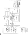
- FIG. 1 is an overall configuration diagram of an operation management system of the present invention.
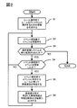
- 1 schematically shows an overall processing flow of failure analysis, which is one embodiment of the present invention.
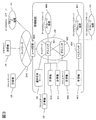
- 1 schematically shows one typical configuration example of an IT system targeted by the present invention.
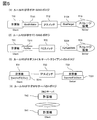
- Fig. 3 schematically shows correlation analysis rule information used in the operation management system of the present invention.
- FIG. 5 schematically shows a topology specified as an application target in the correlation analysis rule information shown in FIG. 4.
- 2 schematically shows a rule application destination management table which is an example of a table-like data structure for managing a list of IT devices to which rules are applied. It is a generation processing flow of application information of correlation analysis rule information which is one of the embodiments of the present invention.
- 2 schematically shows configuration information related to an IP-SAN storage of a management target IT device held by configuration management in the first embodiment of the present invention. It is an example of a screen display which proposes to a user to include an unmanaged IT apparatus in a management object in a first embodiment of the present invention.
- 2 schematically shows an unmanaged IT device management table as an example of a table-like data structure for managing unmanaged IT devices in the first embodiment of the present invention.
- 2 schematically shows a rule application destination management table that holds a list of rule application destination IT devices in the first embodiment of the present invention.
- FIG. 2 schematically shows connection information of an FC-SAN storage device acquired by a computer serving as an FC-SAN client in the first embodiment of the present invention.
- 2 schematically shows information related to FC-SAN storage of a management target IT device held by configuration management in the first embodiment of the present invention.
- FIG. 3 schematically shows identification information and a public name related to a file server that can be acquired by a computer serving as a file server in the first embodiment of the present invention.
- the screen display processing flow of a failure analysis result in 1st embodiment of this invention is shown typically.
- 3 schematically shows an example of failure analysis result data when an unmanaged IT device is the cause of a failure in the first embodiment of the present invention.
- FIG. 3 schematically shows an example of a screen display configuration of a failure analysis result when an unmanaged IT device is the cause of a failure in the first embodiment of the present invention.
- 4 schematically shows a screen display of a failure analysis result when an unmanaged IT device is the cause of a failure in the first embodiment of the present invention.
- the whole processing flow of failure analysis in a second embodiment of the present invention is typically shown. It is a generation processing flow of application information of correlation analysis rule information which is one of the embodiments of the present invention.
- FIG. 1 is an overview diagram showing one configuration of an information processing system for carrying out the present invention.
- the information processing system includes an operation management system and an operation management server.
- the operation management system monitors and manages the computers, network switches (NW switches), and storage devices that make up the IT system as management targets and the operation management server N0.
- the operation management server N0 of the present invention has an event receiver C0 that receives event information such as state changes, failure information, and notification information in the IT device to be managed, and a rule R0 that is defined in advance based on the received event information.
- a rule engine C1 that performs failure analysis based on the configuration, a configuration management C3 that manages configuration information of IT devices to be managed, and a screen display unit C2 that outputs information necessary for managing these operations to the screen. It is equipped.
- the operation management system includes a screen output device M1 that is a device for displaying information for operation management on the screen based on control of the screen display unit and output data, and is connected to the operation management server N0.
- the screen output device M1 may be a display device connected to the operation management server in the first place. However, if the analysis result information can be displayed to the administrator of the operation management system, the screen output device M1 may be replaced with another device. May be.
- the screen output device M1 as a screen output device, an e-mail transmitted from the operation management server N0 can be received and displayed, or based on analysis result information transmitted from the operation management server N0.
- the rule engine C1 further reads analysis rule information R0 (hereinafter also referred to as correlation analysis rule information) for event correlation analysis, acquires configuration information T0 from the configuration management C3, and stores the rules in the IT system.
- a rule application unit C11 that performs processing for application to the IT device, and a rule application destination management table C130 that manages application information that is information for applying the rule to the IT device in the rule application unit.
- a rule memory C13 which is a working memory for performing analysis processing, and an event analysis processing unit C12 that receives event information received by the event receiving unit C0 and performs correlation analysis of events.
- the rule application destination management table C130 may be stored in the memory of the operation management server N0 even if it does not exist in the rule memory C13.
- the correlation analysis rule information may be created and stored by the administrator of the operation management server N0, may be stored in the memory by including the correlation analysis rule information in the program of the present invention described later, or Correlation analysis rule information may be stored in the memory by program initialization processing.
- hardware constituting the operation management server N0 includes a processor, a memory (including a secondary storage device represented by a semiconductor memory and an HDD), and a network port. Each hardware is connected by an internal network such as a bus.
- the event receiving unit C0, the route engine C1, the screen display unit C2, and the configuration management C3 are stored in the memory of the operation management server N0 and can be realized as programs executed by the processor. Some or all of the functions may be realized by hardware.
- a program including the event receiving unit C0, the route engine C1, the screen display unit C2, and the configuration management C3 is referred to as an event analysis program.
- the correlation analysis rule information R0, the configuration information T0, and the rule application destination management table C130 are stored in the memory of the operation management server N0. Further, the configuration information T0 will be described later, IP-SAN storage device connection information (FIG. 8), IP-SAN storage information (FIG. 9), FC-SAN storage device connection information (FIG. 13), FC-SAN. Information on storage (FIG. 14), identification information on file server, and public name (FIG. 15) are included. Also, the non-managed IT device management table (FIG. 11), which will be described later, will be described as being included in the configuration information. However, if it is stored in the memory of the operation management server N0, it is stored as information other than the configuration information T0. May be.
- the identification information and public name related to the file server, and the unmanaged IT device management table do not need to have a specific format or data structure such as a text file, a table, or a queue structure, and may include information described later.
- the operation management server stores event information received from various IT devices to be managed in an event database defined in the memory as an event entry.
- the event database may have any data structure as long as one or more event entries are included.
- the event information includes the event content, but may include the event occurrence time. Further, the event database may leave past event information as a history according to a predetermined condition. In addition, when stored in the memory in the event database, the operation management server program (particularly the configuration management C3) associates the identification information of the event information acquisition target IT device with the event information reception time by the operation management server. It may be included.
- the event content includes at least the type of event, and in some cases, the event content may include information that identifies the hardware and software in the IT device in which the event occurred.
- the operating state of the IT device has become a predetermined state (for example, the occurrence of a hardware failure or a software failure is included in this).
- the health check result is a predetermined result.
- the IT device has received a network access that satisfies a predetermined condition (for example, when the number of requests received by the IT device exceeds a predetermined number of times, or when a network packet identified as a requested DoS attack is (This includes the case of receiving a predetermined number of times, and the case of receiving a request from an IT device other than the specified IT device)
- the event analysis program is stored in the memory by a method of installation or copying from a medium such as a DVD-ROM or CD-ROM storing the program, or the program from a program distribution server that can communicate with the operation management server N0.
- a method of receiving (or information that can generate the program on the memory) is conceivable, but other methods may be used
- the root cause of the failure of the information processing system is analyzed by the operation management server N0 described above.
- an IT device to be managed is designated in advance, and necessary information is received from the IT device with event information as an analysis target by correlation analysis.
- the IT devices to be received are determined because the management of all IT devices connected to the network is necessary for the management server processor, memory, hard disk and other storage devices This is to avoid this problem by narrowing down the objects to be managed.
- the management tool is a commercial tool, the number of licenses is often limited depending on the type and number of IT devices to be managed. For this reason, in the IT system, for event information analysis, the operation management server N0 acquires or is permitted to acquire event information (hereinafter, the IT device to be monitored, or the IT device to be managed or managed).
- IT device in-management IT device, or event acquisition target device
- similar expressions apply to computers, switches, routers, storage devices that are the actual status of IT devices
- operation management server IT device in which N0 does not acquire or suppress acquisition of event information hereinafter referred to as an unmonitored IT device, an unmanaged IT device, an unmanaged IT device, an unmanaged IT device, or an event-related information processing device
- an unmonitored IT device an unmanaged IT device, an unmanaged IT device, an unmanaged IT device, or an event-related information processing device
- the IT devices that have been found, confirmed, or managed at least once in the operation management server N0 Classified as having never been discovered, confirmed, or controlled.
- an IT device that has been managed even once, or an IT device that has been discovered or confirmed may be discovered, even if it is not equivalent to an IT device that is monitored and managed
- there is a configuration in which configuration information acquired by confirmation for example, an IP address of an IT device, a host name, or a FQDN (Fully Qualified Domain Name) is held and managed internally.
- an unmanaged IT device that does not have corresponding configuration information in the operation management server N0, and an unmanaged IT device in which part or all of the corresponding configuration information is already stored in the operation management server N0. It is defined as an IT device that is not managed.
- Cases that are not managed by the operation management system include cases where IT devices within the management target use services provided globally, such as DNS servers, firewalls, access rights problems, network configurations, There are cases where information collection for management by the operation management system cannot be sufficiently performed due to inadequate access means.
- the present invention is intended for correlation analysis between a plurality of IT devices existing on a network. However, even if events due to factors that are inherently correlated devices occur at the same time, the clocks of the individual devices are shifted, and the event information transfer timing is also shifted.
- the event information to be analyzed is event information generated or received within a time width (period) predetermined by the program developer or a period determined by the administrator. In addition, even if a factor occurs, the occurrence of an event related to the factor may occur (for example, when a predetermined network service is received from a server computer via a caching process such as a Web service or a DNS service) ), It is necessary to analyze the period rather than the specific time.
- a suitable event is preferably an item that occurs dynamically to some extent.
- the time at which an event occurs in the IT device (or reception by the operation management server) due to the occurrence of a predetermined factor, and the event occurs in another IT device (or operation management in response to the factor) More preferably, the difference in time received by the server is a factor of an event within the period.
- the information considered as the configuration information is preferably the type and number of hardware constituting the IT device, communication identification information and name necessary for communicating with the device, and some IT device management Although it can be changed by a person, quasi-static information is preferable.
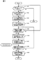
- FIG. 2 shows a rough processing flow of one embodiment of the present invention based on the above configuration.
- the rule engine C1 reads the correlation analysis rule information R0 in advance, acquires the configuration information T0 to be managed from the configuration management C3, searches the identification information of the IT device to which the rule group R0 is applied from T0, It is stored in the rule application destination management table C130.
- the process of S1 is a preparation for a failure analysis process by an event to be performed thereafter, and may be performed before the analysis process.
- the analysis process is performed before the operation is started, and the rule application destination management table C130 is held in the rule memory C13 in advance.
- the event reception unit C0 waits for the reception of an event raised from the IT device to be managed in the operation management system.
- S3 relates to the operation operation of the operation management system, and is a step for confirming whether stop processing has been instructed, and for stopping the operation.
- the specified cause of failure is output to the screen display unit C14.
- the screen display unit C14 outputs and displays a screen necessary for operation management on the screen output device M1 by transmitting analysis information based on the received analysis result output data.
- the received event information may be temporarily stored in the event database as an alternative to the processing of S2 and S4.
- FIG. 3 is an overview diagram showing one configuration of the IT system assumed in the embodiment of the present invention.
- the IT system of FIG. 3 is an operation management target composed of a computer N10, a computer N11, a computer N12 that are managed by the management server N0, an IP switch N21 and an FC switch N31 that are network switches, a storage device N40, and a storage device N41
- the number of IT devices such as computers, switches, routers, storage devices, etc. described here is merely an example, and at least the IT devices that act as servers that provide network services and the clients that receive the network services are provided. It is only necessary that the IT apparatus having the role is included in the operation management system.
- the storage device U1 of the IT device that is not managed is a storage device that has an IP-SAN interface, and provides a logical volume to the managed computer N10. Further, the storage device U2 of the IT device that is not managed is a storage device that has an FC-SAN interface, and provides a logical volume to the managed computer N13 via the managed FC switch N31.
- the computer U3 or the computer U5 of the IT apparatus that is not managed is a file server, and the file system is open to both the managed computers N10 and N11. However, the computer U3 is in a network segment different from the operation management system. Detailed information about the computer U3 cannot be acquired from the network.
- the file server of the computer U5 belongs to the same network segment as the operation management system, and is a computer that can be automatically detected by the operation management system. IT equipment that was not done. Further, the computer U4 of the IT device that is not managed is a DNS server, and the name resolution function is applied to all IT devices of the IT system of FIG.
- FIG. 4 is an example of a rule that suggests that the failure of the controller of the storage apparatus is the root cause for the IT system shown in FIG.
- a rule for identifying the root cause of failure analysis is often based on event correlation and indicates a combination of events predicted to occur and a pair of failure causing the root cause in an if-then format.
- a rule having a meaning such as “if the condition described in if is true, the then part is true” is written.
- the rule is described in the if-then format in the same way as a general rule such as an expert system, and information regarding the IT device to which the rule is applied is defined in the condition part of the if in advance. It shall be.
- the rule description format itself does not have to be an if-then format, and the topology only needs to be defined in advance as some connection / relationship information that can identify the IT device to which the rule is applied.
- the correlation analysis rule information includes one or more rule entries.
- the rule entry may include the following information.
- (A) A condition entry indicating a condition including the type of event to which the rule conforms. As described above, the condition entry may include the topology as a condition.
- (B) A cause entry indicating an event that is a cause when the condition is met and a location of the IT apparatus or the hardware / software of the IT apparatus related to the event.
- a rule R1 based on a controller failure of an IP-SAN storage device using iSCSI a rule R2 based on a controller failure of an FC-SAN storage device using Fiber Channel
- a rule R3 whose root cause is a failure of a file server and a rule R4 whose root cause is a network non-reachability to a DNS server are defined in advance as shown in FIG.
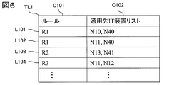
- FIG. 6 shows a rule application destination management table, which is information for holding an IT device to which the rule is applied, for the rule.
- the rule application destination management table is information including a column C101 of identification information indicating a rule and a column C102 of a list of IT devices to which the rule is applied to store the identification information of an IT device to which the rule is applied. Need not be.
- the table-like data structure may be managed by dividing the table into a plurality of table-like data structures by normalizing the table.
- FIG. 5 shows a topology pattern in which each rule is applied to the rules R1 to R4 shown in FIG. (1) in FIG. 5 shows the topology of the connection / relation information suggested by the IF part of the rule R1, and the computer indicating the computer has an iScsiInitiator and indicates the storage device via the IpSwitch indicating the IP switch. Indicates that it is connected to the Storage iScsiTarget.
- the iScsiTarget is an iSCSI name for identifying the connection destination of the iScsiInitiator, and the rule R1 for the combination of the computer and the storage device in which the iSCSI target of the connection destination of the computer and the iSCSI name of the iScsi port of the storage device match. Applies.
- the IT apparatus to which rule R1 is applied is as shown in the rows L101 and L102 in FIG.
- (2) in FIG. 5 also indicates that the computer is provided with FcHba, and FcHba is connected to FcPort of the storage device via FcSwitch, as suggested by the IF part of rule R2.
- the connection destination port WWN WWN (WWN: World Wide Name) possessed by FcHba and FcPortWWN which is the WWN of FcPort which is the port of the Fiber Channel of the storage device are assumed to have a connection relationship, and the rule R2 Applicable.
- the IT device to which the rule R2 is applied as a combination of these computers and storage devices is the row of L103 in FIG.
- the IF part of rule R3 indicates the file server-client topology.
- a computer T31 having information ImportedFileShare indicating that the file system of the file server is mounted, and a computer T33 having information ExportFileShare indicating that the file system is open to the outside are respectively connected to the client ⁇ via the IP switch T32.
- the ImportedFileShare T311 has file server identification information (such as an IP address and FQDN (Fullly Qualified Domain Name)) and the public name of the public file system as the information about the file server of the mount source, and the ExportFileShare T331.
- a file client is a computer pair indicated by the identification information of the file server pointed to by the ImportedFileShare, the computer has the information of the ExportFileShare, and the public name of the ExportFileShare matches the public name pointed to by the ImportedFileShare of the computer T31.
- the topology of the DNS server and client suggested by rule R4 is to resolve the IP address and FQDN name by the computer T42, which is a DNS server providing a name resolution service, and the DNS server.
- the client computer T41 is paired and stored in the application management table shown in FIG.
- the configuration for topology information related to connections and relationships described in these rules is pre-defined in the system and is uniquely determined by the description of the rules.
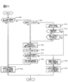
- FIGS. 7 and 21 show one embodiment of the present invention in detail for step S1 in the rule application unit C11 of FIG. According to this processing flow, the first embodiment will be described assuming the IT system of FIG. 3 and the rules R1 to R4 of FIG. 7 and 21 are all performed by the rule application unit. Further, it is assumed that the operation management system stores in advance IT devices that have been discovered once and can determine that the IT device has been discovered. Alternatively, if the operation management system does not have a function to automatically find an IT device in the IT system, or has a function to automatically find an IT device, but does not have a function to store the found IT device, The processing shown in FIGS. 7 and 21 is performed assuming that no discovered IT device exists.
- S101 it is determined whether there is a rule to be read into the correlation analysis rule information information R0, that is, a rule that has not been read. As a result of the determination, if there is a rule to be read (YES), the process proceeds to S102. If not (NO), the process ends. Since the rules to be read exist as R1 to R4, YES is determined here, and the process proceeds to S102.
- one rule is read and, for example, a mark is added or stored as a read rule so that it can be recognized that the rule has been read.
- the rule R1 is read, the rule R1 is stored as a read rule, and the process proceeds to S103.
- the search condition of the IT device corresponding to the topology information described in the rule is obtained, and the process proceeds to S4.
- topology information of the rule R1 as a search condition of the IT device to which the computer having the iScsiInitiator, the storage device having the iSCSI port identified by the iScsiTarget, and the IP switch connected thereto apply the rule R1 Become.
- the search condition is defined in advance for the rule description.
- the client side IT device is searched from the configuration information of the management target IT device in the topology information.
- the configuration information search is performed on the database if the configuration information is managed, and the search is performed on the file if the file is a file, regardless of the storage medium or device to be searched.
- a computer having an iScsiInitiator indicating a client in the topology of the rule R1 is searched from the configuration information.
- the identification information of the computer N10 and the computer N11 is found by the search.
- one of the unselected IT devices is selected and assumed to be selected.
- the computer N10 is selected, and the computer N10 is selected, and the process proceeds to S107.
- the server-side IT device information includes information for identifying the server-side IT device (IP address, host name, FQDN, etc.), information on the service to be provided (public name of the public file system on the file server ( Or a LUN number for identifying a disk volume of a storage device, an iSCSI name of a connection destination, or an FC Port WWN).
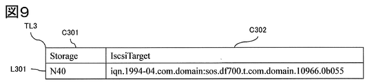
- ConnectedIscsiTarget which is the iSCSI name of the connection destination shown in FIG. 8, is acquired as information on the storage device on the server side facing the computer N10.
- S108 it is determined whether there is information on the server-side IT device acquired in S107 that has not been searched for an IT device corresponding to the information. If YES (YES), the process proceeds to S109. If it does not exist (NO), the process proceeds to S105. In the present embodiment, as shown in FIG. 8, since there are at least three unsearched information (YES), the process proceeds to S109.
- the information includes identification information indicating an IT apparatus (more specifically, a computer) and iSCSI identification information of a storage apparatus to which the IT apparatus is connected. Have.
- one piece of unsearched information is selected from the server-side IT device information acquired in S107, and the server-side IT device is searched from the managed configuration information based on this information.
- the storage device having the iSCSI name shown in the L201 line of the ConnectedIscsiTarget shown in FIG. 8 acquired from the computer N10 in the iScsiTarget is searched from the configuration information to be managed.
- the information includes identification information indicating the storage apparatus and identification information in iSCSI included in the storage apparatus.
- Event acquisition permission / inhibition information indicating whether or not is included in the configuration information T0, and the determination in S110 is performed by referring to the data.
- S111 it is determined whether or not the IT device has already been discovered in the operation management system. That is, whether or not the operation management system is an IT device whose presence has been discovered, confirmed, or managed even once, and the operation management system partially has static configuration information. Judge here. In the present embodiment, there is no configuration information related to the storage apparatus having the iScsiTarget that matches the ConnectedIscsiTarget in the L201 line in FIG. 8, and the process proceeds to S112 assuming that the resource is not a discovered resource (NO).
- the determination in S111 includes a method of determining whether there is information (for example, event acquisition availability information) about the device in the configuration information.
- an attempt is made to discover a storage apparatus having an iScsiTarget that matches the ConnectedIscsiTarget in the L201 line in FIG. 8 from an unmanaged IT apparatus.
- a search method for the presence / absence of an unmanaged IT device in S112 it is acquired from configuration information, or acquired from a communication identifier such as an IP address or FQDN corresponding to a target resource input by a user, or configuration information, or A request for providing a service related to the target resource is transmitted to the IP address in the network address corresponding to the network segment including the target resource input by the user or a communication identifier such as FQDN.
- discovery is attempted from the IT system shown in FIG.
- S113 it is determined whether the discovery attempted in S112 is successful. If successful (YES), the process proceeds to S14. Otherwise (NO), the process proceeds to S116. In this embodiment, the process moves to S114 on the assumption that the storage apparatus U3 shown in FIG. 3 has been found as the corresponding storage apparatus.
- S114 it is determined whether the IT device discovered in S113 can be a management target of the operation management system. Judgment as to whether or not it can be managed is based on whether or not the information necessary for the operation management system to monitor and manage can be acquired from the target IT device. Information required for monitoring and management varies depending on the operation management system. Common information includes information for identifying the IT device, for example, an IP address, or WWN (World Wide Name), Alternatively, it is at least one piece of information such as some unique identification information (number), device name (host name), FQDN, or the like.
- the operation management server N0 has a predetermined criterion and makes this determination based on the criterion.
- the information related to the storage device U3 it is determined that this storage device has an iSCSI port, and that the iSCSI name of the iSCSI port can be obtained as the iSCSI target information and can be managed.
- the process proceeds to S115. Since the device may be a management target in subsequent processing, it is determined in this step that the event information can be received from the IT device in addition to the confirmation processing. Good.
- S115 it is shown to the user whether or not the IT apparatus discovered in S113 is to be managed.
- the storage device U3 is discovered as a storage server of the computer N1, and whether or not the storage device U3 is to be managed is presented.
- the presentation screen is shown in FIG.
- the operation management server N0 (particularly the rule engine) receives an input from the management screen output device.
- S117 it is determined whether or not the IT device discovered by the user is a management target. If the IT device is a management target (YES), the process proceeds to S118. Otherwise (NO), the process proceeds to S119. In this embodiment, it is assumed that the user has not managed the storage apparatus U3, and the process proceeds to S119.
- the server opposite to the client is stored and managed as information that can be acquired in the unmanaged IT device management table as an unmanaged IT device, and the process proceeds to S120.
- the FQDN as information for identifying the apparatus and the iSCSI name of the storage apparatus's IP port, iScsiTarget, can be acquired.
- table TL3 the storage apparatus U3
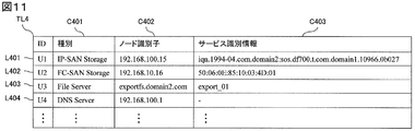
- the management harm IT apparatus management table TL3 contains the following information about each unmanaged IT apparatus discovered.
- A Identification information of unmanaged IT device
- B C401 which is the type of unmanaged IT device
- C C402 which is communication identification information of an unmanaged IT device
- D C403 which is identification information necessary for accessing the service of the unmanaged IT device
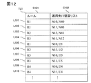
- the identification information of the unmanaged IT device is stored in the rule application destination management table TL1 as shown in FIG. 12, after being marked so that the IT device is unmanaged.
- the identification information is stored in the rule application destination management table TL1 based on the information in the unmanaged IT device management table regarding the storage device U3.
- the process returns to S8 as to whether there is search information related to the server-side IT device opposite to the selected client-side IT device.
- the storage device corresponding to L202 is searched by configuration management.
- the IT device for L202 is a management target, so in S110 it is determined that it is a management target IT device and the process moves to S120.
- a list of the storage device N40 and the computer N10 as IT devices to be managed is stored in L101 of the rule application destination management table of FIG. 11 as an application destination IT device of rule R1.
- the rule R1 can be applied to the unmanaged storage device U1 that provides the logical volume to the computer N10.
- Steps 601 to 603 in FIG. 16 the screen marking unit C2 acquires failure analysis result data D1 indicating the result of failure analysis in the rule engine shown in FIG. 17 from the rule engine C1.
- the rule engine C1 (particularly the event processing analysis unit C12) performs the processing described in S4 of FIG. 2, and FIGS.
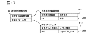
- the failure analysis result data D1 includes data including failure cause IT device information that is information related to the failure cause IT device, and a received event list that is information related to events of the management target IT device received by the operation management system.
- the failure cause IT device information D11 includes information indicating the failure cause IT device and information related to the location of the failure location. The information regarding the location of the fault location depends on how much fault information can be acquired from the fault-causing IT device that is an IT device that is not managed. When failure information cannot be acquired at all, it becomes unknown as shown in FIG.
- the received event list includes a received event source that is information related to a received event that is related to the received event in the rule defined for the failure, an event type that indicates information related to the content of the event, and including.
- the unmanaged IT device management table of FIG. 11 is searched based on the information of the failure cause IT device in the failure analysis result data D11, and information related to the unmanaged IT device is acquired, and the process proceeds to S606.
- the storage device U1 is acquired from L401 in FIG.
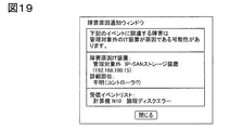
- the configuration example of the screen at that time is related to a message that the unmanaged IT device is the root cause of the failure, a failure analysis result that is a result of analyzing the cause of the failure, and a failure that has occurred.
- a screen display such as a window or a dialog including failure information detected by the operation management system, for example, a received event, is output to the screen output device M1.
- An example of a screen display in the case where the failure of the storage U1, which is an unmanaged IT apparatus of the present embodiment, is the root cause is as shown in FIG.
- Information indicating that the failure cause IT device is not a management target and what type of IT device is, for example, an IP-SAN storage device. For example, an IP address of 192.168 .. It is a screen display including that it is 100.15.
- the process proceeds to S102.
- the rule R2 is read, and R2 is marked as read.
- the topology information described in rule R2 is the FC-SAN topology shown in (2) of FIG. 4, and the server is connected via the Fiber Channel Host Bus Adapter on the client side, that is, the computer T21 having FcHbaT211 and the FC switch T22.
- the topology to which the storage device T23 having FcPortT231, which is the port of the Fiber Channel, is connected on the side is determined as a search condition.
- the computer N13 is selected and is selected.
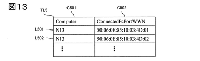
- the Connected FcPortWWN C502 indicating the WWN of the FC Port that is the Fiber Channel port of the storage device on the server side of the connection destination is collected from the computer N13.
- connection information of the FC-SAN storage apparatus in FIG. 13 will be described.
- the information corresponding to each IT apparatus includes the Fiber Channel communication identification information of the connection destination storage apparatus.
- the Connected FcPortWWN which is the search information related to the storage device connected to the computer N13, has not been searched, and the process advances to S109.
- the information includes identification information indicating the storage device and communication identification information in the Fiber Channel included in the storage device.
- FIG. 10 shows an example of screen display according to the rule R1, but the configuration of the screen display is basically the same, and only the contents of the message are replaced with those of the actual IT device.
- the identification information of the storage apparatus U2 and the instruction information for managing the apparatus are received from the administrator.
- Information acquired as a management target is event information and configuration management information.
- the storage apparatus U2 is registered as an IT apparatus to be managed in the rule application destination management table together with the computer N14 as an application destination IT apparatus of the rule R2.
- the data is registered in a table-like data structure including the column C101 of the rule shown in FIG. 12 and the column C102 that stores the IT device list to which the rule is applied.
- the failure analysis of the FC-SAN storage device that is an IT device that is not a management target can be performed for the rule R2 by the conventional rule-based event correlation.
- the IP-SAN storage that is not managed by rule R1 Is performed in the steps of FIG. 16 in the same manner as the process of displaying the screen as the root cause of the failure.
- rule R3 Since there is rule R3 in S101, the process proceeds to S102.
- rule R3 is read and R103 is marked as read.
- R103 as the topology information described in the rule R3, as the topology of the file server / client of FIG. 4 (3), the computer T31 having the ImportedFileShareT311 indicating that the file system disclosed on the client side is mounted, The topology to which the computer T33 having the ExportFileShare T331 indicating that the server side has a file system open to other computers is connected to the server side via the IP switch T32.
- the computer N10 is the client-side IT device that has been searched for and has not been selected, so the process proceeds to S106.
- the computer N10 of FIG. 3 is selected as an unselected client-side IT device, and is selected.
- the information of ImportedFileShare indicating which file server's public file system is mounted is obtained as search information of the computer facing the computer N10 as the server-side IT device of the topology of (3) in FIG. .
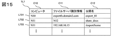
- a column C701 of the client side computer as shown in FIG. 15 As a table for managing information on the file server acquired from the client side, a column C701 of the client side computer as shown in FIG. 15, a column C702 of identification information about the corresponding file server, and a column C703 about the public name of the file server It is managed by a data structure including, for example, a table.
- Information regarding the file server acquired from the client side may be acquired in advance in the table of FIG. 15 as configuration information, or may be acquired from the client side IT apparatus in the processing of S7. That is, the acquisition timing may be performed until the processing of S107 is completed.
- the information included in FIG. 15 will be described.
- the information includes the following information for each individual file server.
- A Identification information of file server as IT device
- B Identification information and public name as one or more file servers
- S108 information on the file server on the client side acquired in S107 is shown in line L701 in FIG. Since there is no search, the process proceeds to S9.
- exportfs. domain2. try to find a computer called com.
- the DNS server is inquired to resolve the IP address, and the existence of the IP address is confirmed by pinging, and then access is attempted by telnet, ssh, or Windows (registered trademark) remote connection.
- exportfs. domain2. The ping for the IP address to com returns success and the existence can be confirmed, but since it does not have the authentication information of the server, the other access fails and the process proceeds to S114 assuming that login is impossible.
- exportfs. domain2. com is registered in the unmanaged IT device management table of FIG. Specifically, information acquired on the client side is stored in the file server identification information and the service identification information as indicated by L403 in FIG.
- the rule application information for the pair of com with the computer U is generated. Specifically, as in L107 of FIG. 121, the computer N10 and the computer U3 that is an unmanaged IT device are registered in the application IT device list for the rule R3.
- the failure analysis can be performed on the computer U3 that is an unmanaged IT device that is a file server of the computer N10.
- S115 a screen for suggesting that the computer U5 is included in the management target is displayed, and in S116, the user receives an instruction to manage the computer U5 as a user input in S116.
- the rule N3 is stored in the rule memory as a data structure as shown in the L108 line in FIG. 12 so that the rule R3 can be applied to the topology in which the computer N11 is the client as the IT device within management and the computer U5 is the file server.
- the failure analysis for the computer U5 of the file server that has been discovered and is not subject to management can be performed according to the flow of FIG. 2, and the screen display unit C2 performs the flow of FIG.
- the cause of the failure can be output to the display device M1.
- step S101 to S104 the computer N10 is found as an IT device on the client side for the rule R4.
- steps S105 to S107 the DNS server IP address 192.168.100.1 is acquired from the computer N10 as DNS server search information for the computer N10.
- steps S108 to S110 using the acquired IP address 192.168.100.1, it is confirmed that there is no DNS server in the configuration information T0 to be managed by the configuration management C3, and the process proceeds to S111.
- S111 it is determined that the DNS server is not a discovered IT device, and the process proceeds to S112.
- S112 an attempt is made to access the node having the IP address 192.168.100.1 from the real IT system.
- the process proceeds to S119.
- the computer with the IP address 192.168.100.1 is the non-management-target IT device, and the information is stored and managed as the DNS server with the identification information U4 as shown in L404 of FIG. 11, and the process proceeds to S120.
- the client computer N10 and the computer U4 of the unmanaged IT device that is the DNS server are stored as the application device list to which rule 4 is applied as shown in line L109 in FIG.
- the failure analysis of the computer U4 which is an unmanaged DNS server, can be analyzed by event correlation based on the conventional rules, and the unmanaged DNS server can be identified as the cause of the failure.
- the application of rule 4 to the other IT devices in FIG. 3 can be similarly performed by generating application information for the computer U4 which is an unmanaged DNS server.
- the flow shown in FIG. 16 is performed on the screen display unit C2, thereby displaying on the screen that the DNS server, which is an unmanaged IT device, is the root cause of the failure. be able to.
- the processing procedure of the overall processing flow of the failure analysis shown in FIG. 2 in the first embodiment is created in the application information in the rule application unit C11 as shown in FIG. Step S4b is performed after step S3b for receiving an event and before step S5b of the event analysis process in the event analysis unit C12.
- the difference between the second embodiment and the first embodiment is only the timing of creating rule application information.
- the present invention is implemented by changing the timing of rule application information, the effect is not impaired, and it is possible to display an IT device that is not a management target on the screen as a root cause device of a failure. .
- the realized program has a part or all of the following processing.
- identification information of a server device that is a part of the plurality of information processing devices to be accessed in order to use a network service as a client is used as configuration information included in the memory.
- Configuration information storage processing to be stored.
- Rule storage process (D) Event storage processing for storing a plurality of pieces of event information collected from the plurality of event acquisition target devices in the memory.
- Event information specifying processing for specifying first event information including the first event type from the plurality of event information stored in the memory based on the correlation analysis rule information.
- Event information specifying processing for specifying first event information including the first event type from the plurality of event information stored in the memory based on the correlation analysis rule information.
- the first event acquisition target device that is one of the event acquisition target devices that transmitted the first event information, and the network service corresponding to the first event type Factor identification processing for identifying a failure factor device that is a server device of the first event acquisition target device.
- the correlation analysis rule information includes a first information processing device that is one of the plurality of information processing devices in which the first event type has occurred, and the plurality of information in which the second event type has occurred.
- Topology condition information indicating a topology condition between the second information processing apparatus that is one of the processing apparatuses may be included, and the factor specifying step may specify the failure factor apparatus based on the topology condition information . Since the information processing apparatus in which an event has occurred by such a process can present an estimation limited to the information processing apparatus actually used, it is more convenient for the user of the operation management server.
- the operation management server may have the following processing.
- H Based on the correlation analysis rule information and the configuration information, the server device of the plurality of event acquisition target devices, the one of the plurality of information processing devices not included in the plurality of event acquisition target devices Related device identification processing for identifying an event-related information processing device that is a section.
- I Event information acquisition possibility investigation processing for investigating whether event information can be obtained from the event-related information processing apparatus.
- J Based on the result of the investigation, when event information can be acquired from the event-related information processing device, information identifying the event-related information processing device is transmitted to the screen output device, so that the event Event information acquisition target addition proposal processing for displaying on the screen output device that event information can be acquired from the related information processing device.
- Such processing can be performed quickly and without forgetting to register from the time when event monitoring is newly required or possible on the operation management server due to changes in the information processing device administrator or management method. Can be promoted.
- the event information acquisition possibility investigation processing is performed on the operation management server with respect to an information processing apparatus having an IP address included in a range of IP addresses set in advance as the investigation range. May be based on the result of access based on a predetermined procedure.
- an information processing device especially a server computer accessed via the Internet
- access is made by the investigation process May be regarded as unauthorized access or unauthorized attack by access monitoring. Therefore, by identifying the IP address of an information processing device that is obviously not subject to event monitoring, or the range of IP addresses of information processing devices that can be subject to event monitoring, it is misidentified as such unauthorized access or unauthorized attack. Communication can be suppressed.
- the failure factor device is a storage device that has a controller and provides a logical volume
- the network service is a service that provides the logical volume by a block access type protocol (for example, Fiber Channel or iSCSI).
- the first event type may be a failure of the storage apparatus, and the first event type may be an access failure to the logical volume.
- the failure factor device is a computer that provides DNS as the network service, wherein the first event type is a DNS request failure and the first event type is a DNS server communication interruption. Good.
- the failure factor device is a file server computer having a NIC that receives data from at least one of the plurality of information processing devices and providing a stored file to at least one of the plurality of information processing devices.
- the network service is a network file sharing service for sharing files stored in the file server computer, and the first event type is the occurrence of a failure of the file server (for example, the occurrence of a NIC failure, the processor of the file server) Even if the first event type is a failure to access the file provided by the network file sharing service) Good.
- the plurality of event information includes the second event type, Identifying the second event information from which the failure factor device is the acquisition source, and information identifying the first event acquisition target device, the first event information, the failure factor device, and the second event information;
- an event corresponding to the first event information generated in the first event acquisition target device is an event corresponding to the second event information generated in the failure factor device. It may be displayed on the screen output device that the occurrence is a factor.
- the first information processing device is a computer
- the second information processing device is a storage device
- the topology condition information indicates a connection relationship of a topology in which the computer and the storage device are connected.
- a combination of communication identification information corresponding to a computer and communication identification information corresponding to the storage device may be included.
- the communication identification information may be at least one of an iSCSI name, an IP address, and a WWN in Fiber Channel.
- the first information processing apparatus is a computer
- the second information processing apparatus is a file server computer that provides a file stored by a file sharing service to the plurality of information processing apparatuses
- the topology condition information is: Including a combination of communication identification information corresponding to the computer indicating a topology connection relationship between the computer and the file server computer, and communication identification information corresponding to the file server computer or an export name for publishing the file Also good.
- the first information processing apparatus is a computer
- the second information processing apparatus is a DNS server computer that provides a DNS as a network sharing service to the plurality of information processing apparatuses
- the topology condition information is stored in the computer.
- a combination of communication identification information corresponding to the computer indicating a connection relationship of a topology connected to the DNS server computer and communication identification information corresponding to the DNS server computer.
- the communication identification information corresponding to the computer and the communication identification information corresponding to the DNS server computer may be IP addresses or FQDNs.
- the operation management server may be composed of one or more computers.
Abstract
Description
本発明の一実施例によると、前記運用管理サーバについて、前記複数の情報処理装置の各々が、クライアントとしてネットワークサービスを用いるためにアクセス対象とする前記複数の情報処理装置の一部であるサーバ装置の識別情報を、前記メモリが有する構成情報に格納し、前記複数の情報処理装置の一部であって、前記運用管理サーバがイベント情報を取得する対象である複数のイベント取得対象装置を前記メモリが有する構成情報に登録し、前記複数の情報処理装置で発生する前記ネットワークサービスに関連した第一のイベント種別を含むイベントと、前記ネットワークサービスに関連した前記第一のイベント種別とは異なる第二のイベント種別を含むイベントと、を検知した場合に、前記第二のイベント種別に対応するイベントの発生が原因で前記第一のイベント種別に対応するイベントが発生し得ることを示す相関解析ルール情報を前記メモリに格納し、前記複数のイベント取得対象装置から収集した複数の前記イベント情報を前記メモリに格納し、前記相関解析ルール情報を元に、前記メモリに格納した複数の前記イベント情報から、前記第一のイベント種別を含む第一のイベント情報を特定し、前記構成情報を元に、前記第一のイベント情報を送信したイベント取得対象装置の一つである第一イベント取得対象装置と、前記第一のイベント種別に対応する前記ネットワークサービスにおける前記第一イベント取得対象装置のサーバ装置である障害要因装置とを特定し、前記相関解析ルール情報と前記構成情報とを元に、前記障害要因装置が前記複数のイベント取得対象装置でない場合に、前記第一イベント取得対象装置と前記第一のイベント種別と前記障害要因装置と前記第二のイベント種別とを特定する情報を前記画面出力装置へ送信することで、前記第一イベント取得対象装置で発生した前記第一のイベント情報に対応したイベントが、前記障害要因装置で前記第二のイベント種別のイベントが発生したことが要因と推定されることを前記画面出力装置へ表示させる。
また、前記相関解析ルール情報と前記構成情報とを元に、前記障害要因装置が前記複数のイベント取得対象装置の一つの場合に、複数の前記イベント情報から前記第二のイベント種別を含み、前記障害要因装置が取得元である第二のイベント情報を特定し、前記第一イベント取得対象装置と前記第一のイベント情報と前記障害要因装置と前記第二のイベント情報とを特定する情報を前記画面出力装置へ送信することで、前記第一イベント取得対象装置で発生した前記第一のイベント情報に対応したイベントが、前記障害要因装置で発生した前記第二のイベント情報に対応したイベントが発生したことが要因であることを前記画面出力装置へ表示させてもよい。
また、本発明の別な一実施例によると、運用管理サーバにて、イベント情報取得対象の情報処理装置をイベント取得対象装置として構成情報に登録し、運用管理サーバに格納した複数のイベント情報から、予め格納したルールに適合するイベント情報を特定し、当該イベント情報が関連するネットワークサービスのサーバ装置を特定し、イベント情報を生成したクライアント情報処理装置で発生した当該イベントの要因がサーバ装置で発生したネットワークサービスに関するイベントと推定されることを表示する。
N1乃至N3...計算機
N4...ネットワーク(NW)スイッチ
N5...ストレージ装置
O1...計算機
O2...NWスイッチ
O3...ストレージ装置
M1...画面出力装置
情報処理システムは運用管理システムと、運用管理サーバから構成される。運用管理システムは、ITシステムを構成する計算機、ネットワークスイッチ(NWスイッチ)、及びストレージ装置を管理対象として、運用管理サーバN0でこれらを監視・管理している。
本発明の運用管理サーバN0は、管理対象のIT装置における状態変化、障害情報、通知情報などのイベント情報を受信するイベント受信部C0と、受信したイベント情報にもとづき、予め定義されたルールR0にもとづいて障害解析を行うルールエンジンC1と、管理対象のIT装置の構成情報を管理する構成管理C3と、これらの運用管理するために必要となる情報を画面に出力するための画面表示部C2が備わっている。
(A)当該IT装置のの稼動状態が予め定められた状態となったこと(例えばハードウェア障害や、ソフトウェア障害の発生がこれに含まれる)
(B)ヘルスチェック結果が予め定められた結果となったこと。(例えば一定時間ヘルスチェック応答が無かった場合がこれに含まれる)
(C)処理速度やIT装置を構成するコンポーネントであるプロセッサやメモリ、HDDなどの消費リソース量が予め定められた条件に適合したこと(例えばHDDの残り容量が10%を下回った場合がこれに含まれる)
(D)IT装置が予め定められた条件を満たすネットワークアクセスを受信したこと(例えば、IT装置が受信したリクエストが所定の回数を超えた場合や、リクエストされたDoS攻撃と識別されるネットワークパケットを所定回数受信した場合や、定められたIT装置以外のIT装置からリクエストを受信した場合がこれに含まれる)
なお、イベント解析プログラムのメモリへの格納は当該プログラムを記憶したDVD-ROMやCD-ROM等の媒体からのインストールやコピーによる方法や、運用管理サーバN0と通信可能なプログラム配布サーバからの当該プログラム(または当該プログラムをメモリ上で生成可能な情報)を受信する方法が考えられるが、これ以外の方法であってもよい。また、運用管理サーバN0へのプログラム格納を予め格納した後で運用管理サーバN0を流通させる形態であってもよい。
(A)当該ルールが適合するイベントの種別を含んだ条件を示す条件エントリ。上記の通り、この条件エントリにはトポロジを条件として含めてもよい。
(B)当該条件が適合した場合に原因となるイベントと、当該イベントが関係するIT装置又はIT装置のハードウェア・ソフトウェアの箇所を表す原因エントリ。
S101において、相関解析ルール情報情報R0に読み込むルール、すなわち読み込み済みでないルールが存在するかを判断する。判断の結果、読み込むルールが存在する(YESの)場合には、S102に移る。そうでなければ(NOの場合)終了する。読み込むルールはR1乃至R4と存在するので、ここではYESとなりS102に移る。
(A)管理外IT装置の識別情報
(B)管理外IT装置の種別であるC401
(C)管理外IT装置の通信識別情報であるC402
(D)管理外IT装置のサービスにアクセスするために必要な識別情報であるC403
S120においては、管理外IT装置の識別情報を、該IT装置が管理外であることがわかるような印をつけた上で、図12に示すようにルール適用先管理テーブルTL1に格納する。本実施例では、ストレージ装置U3に関する管理外IT装置管理テーブルの情報を元に識別情報を、ルール適用先管理テーブルTL1に格納する。格納した後、選択したクライアント側のIT装置に対向するサーバ側のIT装置に関する検索情報が存在するかについてS8に戻る。
ルールR2について、図3のITシステムを対象とした実施例をもとにフローを説明する。
なお、障害解析の結果データを元に、管理対象外のIT装置であるFC-SANストレージが障害の根本原因であると画面表示を出す処理については、ルールR1の管理対象外のIP-SANストレージを障害の根本原因であると画面表示した処理と同様にして図16のステップで行う。
(ルールR3についての処理フロー)
ルールR3について、図3のITシステムを対象とした実施例をもとにフローを説明する。
(A)ファイルサーバーのIT装置としての識別情報
(B)一つ以上のファイルサーバとしての識別情報と公開名
S108において、S107で取得したクライアント側のファイルサーバに関する情報は、図15のL701行であり、未検索であるためS9に進む。
S105からS107のステップにより、計算機N11に対するファイルサーバとして
図15のL703の行に示したファイルサーバに関する情報を取得する。S109において管理対象のIT装置に図15のL703行で示されたファイルサーバは見つからないため、S111に進む。S111においては、発見済みのリソースの中に図15のL703行で示されたIPアドレスを持つ計算機U5が存在するので、S115に進む。
ルールR4について、図3のITシステムを対象とした実施例をもとにフローを説明する。
この第2実施形態と、第1実施形態の違いは、ルールの適用情報を作成するタイミングのみである。
(a)前記複数の情報処理装置の各々が、クライアントとしてネットワークサービスを用いるためにアクセス対象とする前記複数の情報処理装置の一部であるサーバ装置の識別情報を、前記メモリが有する構成情報に格納する構成情報格納処理。
(b)前記複数の情報処理装置の一部であって、前記運用管理サーバがイベント情報を取得する対象である複数のイベント取得対象装置を前記メモリが有する構成情報に登録する登録処理。
(c)前記複数の情報処理装置で発生する前記ネットワークサービスに関連した第一のイベント種別を含むイベントと、前記ネットワークサービスに関連した前記第一のイベント種別とは異なる第二のイベント種別を含むイベントと、を検知した場合に、前記第二のイベント種別に対応するイベントの発生が原因で前記第一のイベント種別に対応するイベントが発生し得ることを示す相関解析ルール情報を前記メモリに格納するルール格納処理。
(d)前記複数のイベント取得対象装置から収集した複数の前記イベント情報を前記メモリに格納するイベント格納処理。
(e)前記相関解析ルール情報を元に、前記メモリに格納した複数の前記イベント情報から、前記第一のイベント種別を含む第一のイベント情報を特定するイベント情報特定処理。
(f)前記構成情報を元に、前記第一のイベント情報を送信したイベント取得対象装置の一つである第一イベント取得対象装置と、前記第一のイベント種別に対応する前記ネットワークサービスにおける前記第一イベント取得対象装置のサーバ装置である障害要因装置とを特定する、要因特定処理。
(g)前記相関解析ルール情報と前記構成情報とを元に、前記障害要因装置が前記複数のイベント取得対象装置でない場合に、前記第一イベント取得対象装置と前記第一のイベント種別と前記障害要因装置と前記第二のイベント種別とを特定する情報を前記画面出力装置へ送信することで、前記第一イベント取得対象装置で発生した前記第一のイベント情報に対応したイベントが、前記障害要因装置で前記第二のイベント種別のイベントが発生したことが要因と推定されることを前記画面出力装置へ表示させる解析結果送信処理。
(h)前記相関解析ルール情報と前記構成情報に基づいて、前記複数のイベント取得対象装置のサーバ装置であって、前記複数のイベント取得対象装置に含まれない、前記複数の情報処理装置の一部であるイベント関連情報処理装置を特定する、関連装置特定処理。
(i)前記イベント関連情報処理装置からイベント情報の取得が可能か調査する、イベント情報取得可否調査処理。
(j)前記調査の結果を元に、前記イベント関連情報処理装置からイベント情報の取得が可能な場合は前記イベント関連情報処理装置を特定する情報を前記画面出力装置へ送信することで、前記イベント関連情報処理装置からイベント情報の取得が可能であることを前記画面出力装置へ表示させる、イベント情報取得対象追加提案処理。
Claims (14)
- 複数の情報処理装置と画面出力装置とに接続され、プロセッサとメモリを有する運用管理サーバにおける前記複数の情報処理装置で発生するイベントの解析方法であって、
前記複数の情報処理装置の各々が、クライアントとしてネットワークサービスを用いるためにアクセス対象とする前記複数の情報処理装置の一部であるサーバ装置の識別情報を、前記メモリが有する構成情報に格納する構成情報格納ステップと、
前記複数の情報処理装置の一部であって、前記運用管理サーバがイベント情報を取得する対象である複数のイベント取得対象装置を前記メモリが有する構成情報に登録する登録ステップと、
前記複数の情報処理装置で発生する前記ネットワークサービスに関連した第一のイベント種別を含むイベントと、前記ネットワークサービスに関連した前記第一のイベント種別とは異なる第二のイベント種別を含むイベントと、を検知した場合に、前記第二のイベント種別に対応するイベントの発生が原因で前記第一のイベント種別に対応するイベントが発生し得ることを示す相関解析ルール情報を前記メモリに格納するルール格納ステップと、
前記複数のイベント取得対象装置から収集した複数の前記イベント情報を前記メモリに格納するイベント格納ステップと、
前記相関解析ルール情報を元に、前記メモリに格納した複数の前記イベント情報から、前記第一のイベント種別を含む第一のイベント情報を特定するイベント情報特定ステップと、
前記構成情報を元に、前記第一のイベント情報を送信したイベント取得対象装置の一つである第一イベント取得対象装置と、前記第一のイベント種別に対応する前記ネットワークサービスにおける前記第一イベント取得対象装置のサーバ装置である障害要因装置とを特定する、要因特定ステップと、
前記相関解析ルール情報と前記構成情報とを元に、前記障害要因装置が前記複数のイベント取得対象装置でない場合に、前記第一イベント取得対象装置と前記第一のイベント種別と前記障害要因装置と前記第二のイベント種別とを特定する情報を前記画面出力装置へ送信することで、前記第一イベント取得対象装置で発生した前記第一のイベント情報に対応したイベントが、前記障害要因装置で前記第二のイベント種別のイベントが発生したことが要因と推定されることを前記画面出力装置へ表示させる解析結果送信ステップと、
を有することを特徴としたイベントの解析方法。 - 請求項1記載のイベント解析方法であって、
前記相関解析ルール情報は、前記第一のイベント種別が発生した前記複数の情報処理装置の一つである第一情報処理装置と、前記第二のイベント種別が発生した前記複数の情報処理装置の一つである第二情報処理装置と、の間のトポロジ条件を示すトポロジ条件情報を含み、
前記要因特定ステップは、前記トポロジ条件情報に基づいて前記障害要因装置を特定する、
ことを特徴としたイベントの解析方法。 - 請求項2記載のイベントの解析方法であって、
前記相関解析ルール情報と前記構成情報に基づいて、前記複数のイベント取得対象装置のサーバ装置であって、前記複数のイベント取得対象装置に含まれない、前記複数の情報処理装置の一部であるイベント関連情報処理装置を特定する、関連装置特定ステップと、
前記イベント関連情報処理装置からイベント情報の取得が可能か調査する、イベント情報取得可否調査ステップと、
前記調査の結果を元に、前記イベント関連情報処理装置からイベント情報の取得が可能な場合は前記イベント関連情報処理装置を特定する情報を前記画面出力装置へ送信することで、前記イベント関連情報処理装置からイベント情報の取得が可能であることを前記画面出力装置へ表示させる、イベント情報取得対象追加提案ステップと、
を有することを特徴としたイベントの解析方法。 - 請求項3記載のイベントの解析方法であって、
前記イベント情報取得可否調査ステップは、前記複数の情報処理装置であって予め調査範囲として設定されたIPアドレスの範囲に含まれるIPアドレスを有する情報処理装置に対して、前記運用管理サーバが所定の手順に基づくアクセスを行った結果に基づくことを特徴としたイベントの解析方法。 - 請求項1記載のイベントの解析方法であって、
前記障害要因装置はコントローラを有し、論理ボリュームを提供するストレージ装置であって、
前記ネットワークサービスは前記論理ボリュームをブロックアクセス形式のプロトコルによって提供するサービスであって、
前記第一のイベント種別が前記ストレージ装置の障害発生であり、前記第一のイベント種別が前記論理ボリュームへのアクセス失敗である、
ことを特徴としたイベントの解析方法。 - 請求項5記載のイベントの解析方法であって、前記ブロックアクセス形式のプロトコルはFibreChannel又はiSCSIであることを特徴としたイベントの解析方法。
- 請求項1記載のイベントの解析方法であって、
前記障害要因装置は前記ネットワークサービスとしてDNSを提供する計算機であって、前記第一のイベント種別がDNS要求失敗であり、前記第一のイベント種別がDNSサーバの通信断絶である、
ことを特徴としたイベントの解析方法。 - 請求項1記載のイベントの解析方法であって、
前記障害要因装置は格納したファイルを前記複数の情報処理装置の少なくとも一つに提供するファイルサーバ計算機であって、
前記ネットワークサービスは前記ファイルサーバ計算機が格納したファイルを共有するネットワークファイル共有サービスであって、
前記第一のイベント種別が前記ファイルサーバ計算機の障害発生であり、前記第一のイベント種別が前記ネットワークファイル共有サービスで提供されたファイルへのアクセス失敗である、
ことを特徴としたイベントの解析方法。 - 請求項1記載のイベントの解析方法であって、
前記相関解析ルール情報と前記構成情報とを元に、前記障害要因装置が前記複数のイベント取得対象装置の一つの場合に、複数の前記イベント情報から前記第二のイベント種別を含み、前記障害要因装置が取得元である第二のイベント情報を特定し、前記第一イベント取得対象装置と前記第一のイベント情報と前記障害要因装置と前記第二のイベント情報とを特定する情報を前記画面出力装置へ送信することで、前記第一イベント取得対象装置で発生した前記第一のイベント情報に対応したイベントが、前記障害要因装置で発生した前記第二のイベント情報に対応したイベントが発生したことが要因であることを前記画面出力装置へ表示させる第二解析結果送信ステップ、
とを有することを特徴としたイベントの解析方法。 - 請求項2記載のイベントの解析方法であって、
前記第一情報処理装置が計算機であり、前記第二情報処理装置がストレージ装置であり、
前記トポロジ条件情報は、前記計算機と前記ストレージ装置とが接続するトポロジの接続関係を示す、前記計算機に対応する通信識別情報と前記ストレージ装置に対応する通信識別情報との組み合わせを含む、
ことを特徴としたイベントの解析方法。 - 請求項10記載のイベントの解析方法であって、
前記計算機に対応する計算機通信識別情報と前記ストレージ装置に対応する通信識別情報とは、iSCSI名と、IPアドレスと、FibreChannelにおけるWWNとの少なくとも一つであることを特徴とするイベントの解析方法。 - 請求項2記載のイベントの解析方法であって、
前記第一情報処理装置が計算機であり、前記第二情報処理装置はファイル共有サービスによって格納したファイルを前記複数の情報処理装置へ提供するファイルサーバ計算機であり、
前記トポロジ条件情報は、前記計算機と前記ファイルサーバ計算機とが接続するトポロジの接続関係を示す前記計算機に対応する通信識別情報と前記ファイルサーバ計算機に対応する通信識別情報又は前記ファイルを公開するエクスポート名との組み合わせを含む、
ことを特徴としたイベントの解析方法。 - 請求項2記載のイベントの解析方法であって、
前記第一情報処理装置は計算機であり、前記第二情報処理装置がネットワーク共有サービスとしてDNSを前記複数の情報処理装置に提供するDNSサーバ計算機であり、
前記トポロジ条件情報は、前記計算機と前記DNSサーバ計算機とが接続するトポロジの接続関係を示す前記計算機に対応する通信識別情報と前記DNSサーバ計算機に対応する通信識別情報との組み合わせを含む、
ことを特徴としたイベントの解析方法。 - 請求項13記載のイベントの解析方法であって、
前記計算機に対応する通信識別情報と前記DNSサーバ計算機に対応する通信識別情報とは、IPアドレス又はFQDNである、
ことを特徴としたイベントの解析方法。
Priority Applications (4)
| Application Number | Priority Date | Filing Date | Title |
|---|---|---|---|
| US12/444,398 US8020045B2 (en) | 2008-09-30 | 2009-01-26 | Root cause analysis method, apparatus, and program for IT apparatuses from which event information is not obtained |
| EP09817371.9A EP2336890A4 (en) | 2008-09-30 | 2009-01-26 | CAUSE ANALYSIS PROCEDURE FOR AN IT DEVICE WHICH DOES NOT IDENTIFY EVENT INFORMATION, AND DEVICE AND PROGRAM THEREFOR |
| CN200980111739.7A CN101981546B (zh) | 2008-09-30 | 2009-01-26 | 以不取得事件信息的it装置为对象的根本原因分析方法、装置及程序 |
| US13/211,694 US8479048B2 (en) | 2008-09-30 | 2011-08-17 | Root cause analysis method, apparatus, and program for IT apparatuses from which event information is not obtained |
Applications Claiming Priority (2)
| Application Number | Priority Date | Filing Date | Title |
|---|---|---|---|
| JP2008252093A JP5237034B2 (ja) | 2008-09-30 | 2008-09-30 | イベント情報取得外のit装置を対象とする根本原因解析方法、装置、プログラム。 |
| JP2008-252093 | 2008-09-30 |
Related Child Applications (2)
| Application Number | Title | Priority Date | Filing Date |
|---|---|---|---|
| US12/444,398 A-371-Of-International US8020045B2 (en) | 2008-09-30 | 2009-01-26 | Root cause analysis method, apparatus, and program for IT apparatuses from which event information is not obtained |
| US13/211,694 Continuation US8479048B2 (en) | 2008-09-30 | 2011-08-17 | Root cause analysis method, apparatus, and program for IT apparatuses from which event information is not obtained |
Publications (1)
| Publication Number | Publication Date |
|---|---|
| WO2010038327A1 true WO2010038327A1 (ja) | 2010-04-08 |
Family
ID=42073117
Family Applications (1)
| Application Number | Title | Priority Date | Filing Date |
|---|---|---|---|
| PCT/JP2009/000285 WO2010038327A1 (ja) | 2008-09-30 | 2009-01-26 | イベント情報取得外のit装置を対象とする根本原因解析方法、装置、プログラム。 |
Country Status (5)
| Country | Link |
|---|---|
| US (2) | US8020045B2 (ja) |
| EP (1) | EP2336890A4 (ja) |
| JP (1) | JP5237034B2 (ja) |
| CN (1) | CN101981546B (ja) |
| WO (1) | WO2010038327A1 (ja) |
Families Citing this family (108)
| Publication number | Priority date | Publication date | Assignee | Title |
|---|---|---|---|---|
| US8112378B2 (en) | 2008-06-17 | 2012-02-07 | Hitachi, Ltd. | Methods and systems for performing root cause analysis |
| JP5325981B2 (ja) * | 2009-05-26 | 2013-10-23 | 株式会社日立製作所 | 管理サーバ及び管理システム |
| JP5385982B2 (ja) * | 2009-07-16 | 2014-01-08 | 株式会社日立製作所 | 障害の根本原因に対応した復旧方法を表す情報を出力する管理システム |
| US7996723B2 (en) * | 2009-12-22 | 2011-08-09 | Xerox Corporation | Continuous, automated discovery of bugs in released software |
| US8411577B2 (en) * | 2010-03-19 | 2013-04-02 | At&T Intellectual Property I, L.P. | Methods, apparatus and articles of manufacture to perform root cause analysis for network events |
| DE102010024966A1 (de) * | 2010-06-24 | 2011-07-07 | Siemens Aktiengesellschaft, 80333 | Verfahren und Softwareprogrammprodukt zum Bestimmen einer Güte einer Informtionstechnischen Anlage |
| WO2012014305A1 (ja) * | 2010-07-29 | 2012-02-02 | 株式会社日立製作所 | システム障害における構成変更事象の影響度推定方法 |
| US8819220B2 (en) | 2010-09-09 | 2014-08-26 | Hitachi, Ltd. | Management method of computer system and management system |
| US8386602B2 (en) | 2010-11-02 | 2013-02-26 | International Business Machines Corporation | Relevant alert delivery in a distributed processing system |
| US8364813B2 (en) | 2010-11-02 | 2013-01-29 | International Business Machines Corporation | Administering incident pools for event and alert analysis |
| US8621277B2 (en) | 2010-12-06 | 2013-12-31 | International Business Machines Corporation | Dynamic administration of component event reporting in a distributed processing system |
| US8868984B2 (en) * | 2010-12-07 | 2014-10-21 | International Business Machines Corporation | Relevant alert delivery in a distributed processing system with event listeners and alert listeners |
| US8805999B2 (en) | 2010-12-07 | 2014-08-12 | International Business Machines Corporation | Administering event reporting rules in a distributed processing system |
| US8737231B2 (en) | 2010-12-07 | 2014-05-27 | International Business Machines Corporation | Dynamic administration of event pools for relevant event and alert analysis during event storms |
| EP2602718A4 (en) | 2011-03-08 | 2015-06-10 | Hitachi Ltd | METHOD FOR MANAGING COMPUTER SYSTEM AND MANAGEMENT DEVICE |
| JP5352027B2 (ja) * | 2011-03-28 | 2013-11-27 | 株式会社日立製作所 | 計算機システムの管理方法及び管理装置 |
| US8756462B2 (en) | 2011-05-24 | 2014-06-17 | International Business Machines Corporation | Configurable alert delivery for reducing the amount of alerts transmitted in a distributed processing system |
| US8645757B2 (en) | 2011-05-26 | 2014-02-04 | International Business Machines Corporation | Administering incident pools for event and alert analysis |
| US8676883B2 (en) | 2011-05-27 | 2014-03-18 | International Business Machines Corporation | Event management in a distributed processing system |
| US9213621B2 (en) | 2011-05-27 | 2015-12-15 | International Business Machines Corporation | Administering event pools for relevant event analysis in a distributed processing system |
| US8880943B2 (en) | 2011-06-22 | 2014-11-04 | International Business Machines Corporation | Restarting event and alert analysis after a shutdown in a distributed processing system |
| US8713366B2 (en) | 2011-06-22 | 2014-04-29 | International Business Machines Corporation | Restarting event and alert analysis after a shutdown in a distributed processing system |
| US9419650B2 (en) | 2011-06-22 | 2016-08-16 | International Business Machines Corporation | Flexible event data content management for relevant event and alert analysis within a distributed processing system |
| US8392385B2 (en) | 2011-06-22 | 2013-03-05 | International Business Machines Corporation | Flexible event data content management for relevant event and alert analysis within a distributed processing system |
| US9389946B2 (en) | 2011-09-19 | 2016-07-12 | Nec Corporation | Operation management apparatus, operation management method, and program |
| US20130097215A1 (en) | 2011-10-18 | 2013-04-18 | International Business Machines Corporation | Selected Alert Delivery In A Distributed Processing System |
| US20130097272A1 (en) | 2011-10-18 | 2013-04-18 | International Business Machines Corporation | Prioritized Alert Delivery In A Distributed Processing System |
| US8887175B2 (en) | 2011-10-18 | 2014-11-11 | International Business Machines Corporation | Administering incident pools for event and alert analysis |
| US9178936B2 (en) | 2011-10-18 | 2015-11-03 | International Business Machines Corporation | Selected alert delivery in a distributed processing system |
| US8713581B2 (en) | 2011-10-27 | 2014-04-29 | International Business Machines Corporation | Selected alert delivery in a distributed processing system |
| WO2013078671A1 (zh) * | 2011-12-02 | 2013-06-06 | 华为技术有限公司 | 一种故障检测方法、网关、用户设备及通信系统 |
| US9092329B2 (en) * | 2011-12-21 | 2015-07-28 | Sap Se | Process integration alerting for business process management |
| WO2013121529A1 (ja) | 2012-02-14 | 2013-08-22 | 株式会社日立製作所 | コンピュータプログラムおよび監視装置 |
| FR2987533B1 (fr) * | 2012-02-23 | 2014-11-28 | Aspserveur | Procede et systeme d'analyse de correlation de defauts pour un centre informatique |
| US9354961B2 (en) * | 2012-03-23 | 2016-05-31 | Hitachi, Ltd. | Method and system for supporting event root cause analysis |
| WO2013157144A1 (ja) * | 2012-04-20 | 2013-10-24 | 富士通株式会社 | プログラム、情報処理装置およびイベント処理方法 |
| WO2013168211A1 (ja) | 2012-05-07 | 2013-11-14 | 株式会社日立製作所 | 計算機システム、ストレージ管理計算機及びストレージ管理方法 |
| WO2014001841A1 (en) | 2012-06-25 | 2014-01-03 | Kni Műszaki Tanácsadó Kft. | Methods of implementing a dynamic service-event management system |
| US9413685B1 (en) | 2012-06-28 | 2016-08-09 | Emc Corporation | Method and apparatus for cross domain and cross-layer event correlation |
| US9298582B1 (en) | 2012-06-28 | 2016-03-29 | Emc Corporation | Method and apparatus for performance data transformation in a cloud computing system |
| US8954811B2 (en) | 2012-08-06 | 2015-02-10 | International Business Machines Corporation | Administering incident pools for incident analysis |
| US8943366B2 (en) | 2012-08-09 | 2015-01-27 | International Business Machines Corporation | Administering checkpoints for incident analysis |
| JP5719974B2 (ja) | 2012-09-03 | 2015-05-20 | 株式会社日立製作所 | 複数の監視対象デバイスを有する計算機システムの管理を行う管理システム |
| US9053000B1 (en) * | 2012-09-27 | 2015-06-09 | Emc Corporation | Method and apparatus for event correlation based on causality equivalence |
| JP6039352B2 (ja) * | 2012-10-12 | 2016-12-07 | キヤノン株式会社 | デバイス管理システム、デバイス管理システムの制御方法、及びプログラム |
| JP6080862B2 (ja) * | 2012-10-30 | 2017-02-15 | 株式会社日立製作所 | 管理計算機およびルール生成方法 |
| US20140297821A1 (en) * | 2013-03-27 | 2014-10-02 | Alcatel-Lucent Usa Inc. | System and method providing learning correlation of event data |
| CN104583968B (zh) | 2013-04-05 | 2017-08-04 | 株式会社日立制作所 | 管理系统及管理程序 |
| US9361184B2 (en) | 2013-05-09 | 2016-06-07 | International Business Machines Corporation | Selecting during a system shutdown procedure, a restart incident checkpoint of an incident analyzer in a distributed processing system |
| US9170860B2 (en) | 2013-07-26 | 2015-10-27 | International Business Machines Corporation | Parallel incident processing |
| WO2015019488A1 (ja) * | 2013-08-09 | 2015-02-12 | 株式会社日立製作所 | 管理システム及びその管理システムによるイベント解析方法 |
| US9658902B2 (en) | 2013-08-22 | 2017-05-23 | Globalfoundries Inc. | Adaptive clock throttling for event processing |
| US9256482B2 (en) | 2013-08-23 | 2016-02-09 | International Business Machines Corporation | Determining whether to send an alert in a distributed processing system |
| US9086968B2 (en) | 2013-09-11 | 2015-07-21 | International Business Machines Corporation | Checkpointing for delayed alert creation |
| US9602337B2 (en) | 2013-09-11 | 2017-03-21 | International Business Machines Corporation | Event and alert analysis in a distributed processing system |
| JP2015076072A (ja) * | 2013-10-11 | 2015-04-20 | キヤノン株式会社 | 監視装置、監視方法、及びプログラム |
| JP6190468B2 (ja) * | 2013-10-30 | 2017-08-30 | 株式会社日立製作所 | 管理システム、プラン生成方法、およびプラン生成プログラム |
| CN103747028B (zh) * | 2013-11-27 | 2018-05-25 | 上海斐讯数据通信技术有限公司 | 一种授予用户临时root权限的方法 |
| DE112013006475T5 (de) * | 2013-11-29 | 2015-10-08 | Hitachi, Ltd. | Verwaltungssystem und Verfahren zur Unterstützung einer Analyse in Bezug auf eine Hauptursache eines Ereignisses |
| US9389943B2 (en) | 2014-01-07 | 2016-07-12 | International Business Machines Corporation | Determining a number of unique incidents in a plurality of incidents for incident processing in a distributed processing system |
| CN106062765B (zh) | 2014-02-26 | 2017-09-22 | 三菱电机株式会社 | 攻击检测装置和攻击检测方法 |
| US10523521B2 (en) | 2014-04-15 | 2019-12-31 | Splunk Inc. | Managing ephemeral event streams generated from captured network data |
| US10127273B2 (en) | 2014-04-15 | 2018-11-13 | Splunk Inc. | Distributed processing of network data using remote capture agents |
| US11086897B2 (en) | 2014-04-15 | 2021-08-10 | Splunk Inc. | Linking event streams across applications of a data intake and query system |
| US10700950B2 (en) | 2014-04-15 | 2020-06-30 | Splunk Inc. | Adjusting network data storage based on event stream statistics |
| US10366101B2 (en) | 2014-04-15 | 2019-07-30 | Splunk Inc. | Bidirectional linking of ephemeral event streams to creators of the ephemeral event streams |
| US9762443B2 (en) * | 2014-04-15 | 2017-09-12 | Splunk Inc. | Transformation of network data at remote capture agents |
| US10462004B2 (en) | 2014-04-15 | 2019-10-29 | Splunk Inc. | Visualizations of statistics associated with captured network data |
| US11281643B2 (en) | 2014-04-15 | 2022-03-22 | Splunk Inc. | Generating event streams including aggregated values from monitored network data |
| US9923767B2 (en) | 2014-04-15 | 2018-03-20 | Splunk Inc. | Dynamic configuration of remote capture agents for network data capture |
| US10360196B2 (en) | 2014-04-15 | 2019-07-23 | Splunk Inc. | Grouping and managing event streams generated from captured network data |
| US10693742B2 (en) | 2014-04-15 | 2020-06-23 | Splunk Inc. | Inline visualizations of metrics related to captured network data |
| US9838512B2 (en) | 2014-10-30 | 2017-12-05 | Splunk Inc. | Protocol-based capture of network data using remote capture agents |
| JP6330456B2 (ja) * | 2014-04-30 | 2018-05-30 | 富士通株式会社 | 相関係数算出方法、相関係数算出プログラムおよび相関係数算出装置 |
| JP2015215639A (ja) * | 2014-05-07 | 2015-12-03 | 株式会社リコー | 障害管理システム、障害管理装置、機器、障害管理方法、及びプログラム |
| JP6287691B2 (ja) * | 2014-08-28 | 2018-03-07 | 富士通株式会社 | 情報処理装置、情報処理方法および情報処理プログラム |
| US9596253B2 (en) | 2014-10-30 | 2017-03-14 | Splunk Inc. | Capture triggers for capturing network data |
| US9946614B2 (en) * | 2014-12-16 | 2018-04-17 | At&T Intellectual Property I, L.P. | Methods, systems, and computer readable storage devices for managing faults in a virtual machine network |
| US10334085B2 (en) | 2015-01-29 | 2019-06-25 | Splunk Inc. | Facilitating custom content extraction from network packets |
| US10067984B2 (en) * | 2016-02-24 | 2018-09-04 | Bank Of America Corporation | Computerized system for evaluating technology stability |
| US10223425B2 (en) * | 2016-02-24 | 2019-03-05 | Bank Of America Corporation | Operational data processor |
| US10366367B2 (en) | 2016-02-24 | 2019-07-30 | Bank Of America Corporation | Computerized system for evaluating and modifying technology change events |
| US10275183B2 (en) * | 2016-02-24 | 2019-04-30 | Bank Of America Corporation | System for categorical data dynamic decoding |
| US10366337B2 (en) | 2016-02-24 | 2019-07-30 | Bank Of America Corporation | Computerized system for evaluating the likelihood of technology change incidents |
| US10275182B2 (en) * | 2016-02-24 | 2019-04-30 | Bank Of America Corporation | System for categorical data encoding |
| US10216798B2 (en) * | 2016-02-24 | 2019-02-26 | Bank Of America Corporation | Technical language processor |
| US10366338B2 (en) | 2016-02-24 | 2019-07-30 | Bank Of America Corporation | Computerized system for evaluating the impact of technology change incidents |
| US10019486B2 (en) * | 2016-02-24 | 2018-07-10 | Bank Of America Corporation | Computerized system for analyzing operational event data |
| US10387230B2 (en) * | 2016-02-24 | 2019-08-20 | Bank Of America Corporation | Technical language processor administration |
| US10430743B2 (en) | 2016-02-24 | 2019-10-01 | Bank Of America Corporation | Computerized system for simulating the likelihood of technology change incidents |
| CN105786635B (zh) * | 2016-03-01 | 2018-10-12 | 国网江苏省电力公司电力科学研究院 | 一种面向故障敏感点动态检测的复杂事件处理系统及方法 |
| US10339032B2 (en) * | 2016-03-29 | 2019-07-02 | Microsoft Technology Licensing, LLD | System for monitoring and reporting performance and correctness issues across design, compile and runtime |
| US10637745B2 (en) * | 2016-07-29 | 2020-04-28 | Cisco Technology, Inc. | Algorithms for root cause analysis |
| CN106778178A (zh) * | 2016-12-28 | 2017-05-31 | 广东虹勤通讯技术有限公司 | 指纹名片的调用方法及装置 |
| CN106844173A (zh) * | 2016-12-29 | 2017-06-13 | 四川九洲电器集团有限责任公司 | 一种信息处理方法及电子设备 |
| JP6870347B2 (ja) * | 2017-01-31 | 2021-05-12 | オムロン株式会社 | 情報処理装置、情報処理プログラムおよび情報処理方法 |
| CN107562632B (zh) * | 2017-09-12 | 2020-08-28 | 北京奇艺世纪科技有限公司 | 针对推荐策略的a/b测试方法及装置 |
| US11075925B2 (en) | 2018-01-31 | 2021-07-27 | EMC IP Holding Company LLC | System and method to enable component inventory and compliance in the platform |
| CN111819915B (zh) * | 2018-03-15 | 2022-08-23 | 株式会社富士 | 安装系统 |
| US10754708B2 (en) | 2018-03-28 | 2020-08-25 | EMC IP Holding Company LLC | Orchestrator and console agnostic method to deploy infrastructure through self-describing deployment templates |
| US10693722B2 (en) | 2018-03-28 | 2020-06-23 | Dell Products L.P. | Agentless method to bring solution and cluster awareness into infrastructure and support management portals |
| US10795756B2 (en) | 2018-04-24 | 2020-10-06 | EMC IP Holding Company LLC | System and method to predictively service and support the solution |
| US11086738B2 (en) * | 2018-04-24 | 2021-08-10 | EMC IP Holding Company LLC | System and method to automate solution level contextual support |
| US11599422B2 (en) | 2018-10-16 | 2023-03-07 | EMC IP Holding Company LLC | System and method for device independent backup in distributed system |
| US10862761B2 (en) | 2019-04-29 | 2020-12-08 | EMC IP Holding Company LLC | System and method for management of distributed systems |
| US11301557B2 (en) | 2019-07-19 | 2022-04-12 | Dell Products L.P. | System and method for data processing device management |
| KR20220083221A (ko) * | 2020-12-11 | 2022-06-20 | 삼성전자주식회사 | IoT 환경의 허브 장치 및 로컬 네트워크 기반 이벤트 처리 방법 |
| US20230259344A1 (en) * | 2022-02-16 | 2023-08-17 | Saudi Arabian Oil Company | System and method for tracking and installing missing software applications |
Citations (6)
| Publication number | Priority date | Publication date | Assignee | Title |
|---|---|---|---|---|
| JPH11259331A (ja) * | 1998-03-13 | 1999-09-24 | Nippon Telegr & Teleph Corp <Ntt> | ネットワークにおける障害箇所検出方法及び装置及びネットワークにおける障害箇所検出プログラムを格納した記憶媒体 |
| JP2004348640A (ja) * | 2003-05-26 | 2004-12-09 | Hitachi Ltd | ネットワーク管理システム及びネットワーク管理方法 |
| JP2005316728A (ja) * | 2004-04-28 | 2005-11-10 | Mitsubishi Electric Corp | 障害解析装置、障害解析方法及び障害解析プログラム |
| JP2006133983A (ja) * | 2004-11-04 | 2006-05-25 | Hitachi Ltd | 情報処理装置、情報処理装置の制御方法、及びプログラム |
| JP2006338305A (ja) * | 2005-06-01 | 2006-12-14 | Toshiba Corp | 監視装置及び監視プログラム |
| JP2007334716A (ja) * | 2006-06-16 | 2007-12-27 | Nec Corp | 運用管理システム、監視装置、被監視装置、運用管理方法及びプログラム |
Family Cites Families (34)
| Publication number | Priority date | Publication date | Assignee | Title |
|---|---|---|---|---|
| US5528516A (en) | 1994-05-25 | 1996-06-18 | System Management Arts, Inc. | Apparatus and method for event correlation and problem reporting |
| US5546452A (en) * | 1995-03-02 | 1996-08-13 | Geotel Communications Corp. | Communications system using a central controller to control at least one network and agent system |
| US6023507A (en) * | 1997-03-17 | 2000-02-08 | Sun Microsystems, Inc. | Automatic remote computer monitoring system |
| US6393386B1 (en) * | 1998-03-26 | 2002-05-21 | Visual Networks Technologies, Inc. | Dynamic modeling of complex networks and prediction of impacts of faults therein |
| US6393474B1 (en) * | 1998-12-31 | 2002-05-21 | 3Com Corporation | Dynamic policy management apparatus and method using active network devices |
| US6292718B2 (en) * | 1999-01-28 | 2001-09-18 | International Business Machines Corp. | Electronic control system |
| CN100384191C (zh) * | 1999-06-10 | 2008-04-23 | 阿尔卡塔尔互联网运行公司 | 基于策略的网络体系结构 |
| US6823299B1 (en) * | 1999-07-09 | 2004-11-23 | Autodesk, Inc. | Modeling objects, systems, and simulations by establishing relationships in an event-driven graph in a computer implemented graphics system |
| US6820042B1 (en) * | 1999-07-23 | 2004-11-16 | Opnet Technologies | Mixed mode network simulator |
| US6654782B1 (en) * | 1999-10-28 | 2003-11-25 | Networks Associates, Inc. | Modular framework for dynamically processing network events using action sets in a distributed computing environment |
| US6829639B1 (en) * | 1999-11-15 | 2004-12-07 | Netvision, Inc. | Method and system for intelligent global event notification and control within a distributed computing environment |
| DE19958825A1 (de) * | 1999-12-07 | 2001-06-13 | Zeiss Carl Jena Gmbh | Verfahren zur Kontrolle eines Steuerungssystems |
| US7197546B1 (en) * | 2000-03-07 | 2007-03-27 | Lucent Technologies Inc. | Inter-domain network management system for multi-layer networks |
| US6871344B2 (en) * | 2000-04-24 | 2005-03-22 | Microsoft Corporation | Configurations for binding software assemblies to application programs |
| US6854069B2 (en) * | 2000-05-02 | 2005-02-08 | Sun Microsystems Inc. | Method and system for achieving high availability in a networked computer system |
| US7237138B2 (en) * | 2000-05-05 | 2007-06-26 | Computer Associates Think, Inc. | Systems and methods for diagnosing faults in computer networks |
| US6915338B1 (en) * | 2000-10-24 | 2005-07-05 | Microsoft Corporation | System and method providing automatic policy enforcement in a multi-computer service application |
| US20030046615A1 (en) * | 2000-12-22 | 2003-03-06 | Alan Stone | System and method for adaptive reliability balancing in distributed programming networks |
| DE10065118A1 (de) * | 2000-12-28 | 2002-07-04 | Bosch Gmbh Robert | System und Verfahren zur Steuerung und/oder Überwachung eines wenigstens zwei Steuergeräte aufweisenden Steuergeräteverbundes |
| US7028228B1 (en) * | 2001-03-28 | 2006-04-11 | The Shoregroup, Inc. | Method and apparatus for identifying problems in computer networks |
| US20030014644A1 (en) * | 2001-05-02 | 2003-01-16 | Burns James E. | Method and system for security policy management |
| DE10162853C1 (de) * | 2001-12-17 | 2003-06-05 | Iav Gmbh | Kraftfahrzeugsteuersystem und Verfahren zur Kraftfahrzeugsteuerung |
| US20030214908A1 (en) * | 2002-03-19 | 2003-11-20 | Anurag Kumar | Methods and apparatus for quality of service control for TCP aggregates at a bottleneck link in the internet |
| US6996500B2 (en) * | 2002-10-30 | 2006-02-07 | Hewlett-Packard Development Company, L.P. | Method for communicating diagnostic data |
| US7263632B2 (en) * | 2003-05-07 | 2007-08-28 | Microsoft Corporation | Programmatic computer problem diagnosis and resolution and automated reporting and updating of the same |
| US7237267B2 (en) * | 2003-10-16 | 2007-06-26 | Cisco Technology, Inc. | Policy-based network security management |
| US6968291B1 (en) * | 2003-11-04 | 2005-11-22 | Sun Microsystems, Inc. | Using and generating finite state machines to monitor system status |
| US7584382B2 (en) * | 2004-02-19 | 2009-09-01 | Microsoft Corporation | Method and system for troubleshooting a misconfiguration of a computer system based on configurations of other computer systems |
| US8131830B2 (en) * | 2004-04-19 | 2012-03-06 | Hewlett-Packard Development Company, L.P. | System and method for providing support services using administrative rights on a client computer |
| US8627149B2 (en) * | 2004-08-30 | 2014-01-07 | International Business Machines Corporation | Techniques for health monitoring and control of application servers |
| US8554916B2 (en) * | 2005-04-11 | 2013-10-08 | Accenture Global Services Gmbh | Service delivery platform and development of new client business models |
| US7464298B2 (en) * | 2005-07-01 | 2008-12-09 | International Business Machines Corporation | Method, system, and computer program product for multi-domain component management |
| US7801712B2 (en) * | 2006-06-15 | 2010-09-21 | Microsoft Corporation | Declaration and consumption of a causality model for probable cause analysis |
| US8208381B2 (en) * | 2007-07-27 | 2012-06-26 | Eg Innovations Pte. Ltd. | Root-cause approach to problem diagnosis in data networks |
-
2008
- 2008-09-30 JP JP2008252093A patent/JP5237034B2/ja not_active Expired - Fee Related
-
2009
- 2009-01-26 WO PCT/JP2009/000285 patent/WO2010038327A1/ja active Application Filing
- 2009-01-26 CN CN200980111739.7A patent/CN101981546B/zh active Active
- 2009-01-26 US US12/444,398 patent/US8020045B2/en not_active Expired - Fee Related
- 2009-01-26 EP EP09817371.9A patent/EP2336890A4/en not_active Withdrawn
-
2011
- 2011-08-17 US US13/211,694 patent/US8479048B2/en active Active
Patent Citations (6)
| Publication number | Priority date | Publication date | Assignee | Title |
|---|---|---|---|---|
| JPH11259331A (ja) * | 1998-03-13 | 1999-09-24 | Nippon Telegr & Teleph Corp <Ntt> | ネットワークにおける障害箇所検出方法及び装置及びネットワークにおける障害箇所検出プログラムを格納した記憶媒体 |
| JP2004348640A (ja) * | 2003-05-26 | 2004-12-09 | Hitachi Ltd | ネットワーク管理システム及びネットワーク管理方法 |
| JP2005316728A (ja) * | 2004-04-28 | 2005-11-10 | Mitsubishi Electric Corp | 障害解析装置、障害解析方法及び障害解析プログラム |
| JP2006133983A (ja) * | 2004-11-04 | 2006-05-25 | Hitachi Ltd | 情報処理装置、情報処理装置の制御方法、及びプログラム |
| JP2006338305A (ja) * | 2005-06-01 | 2006-12-14 | Toshiba Corp | 監視装置及び監視プログラム |
| JP2007334716A (ja) * | 2006-06-16 | 2007-12-27 | Nec Corp | 運用管理システム、監視装置、被監視装置、運用管理方法及びプログラム |
Non-Patent Citations (2)
| Title |
|---|
| "Rete: A Fast Algorithm for the Many Pattern/Many Object Pattern Match Problem", ARTIFICIAL INTELLIGENCE, vol. 19, no. 1, 1982, pages 17 - 37 |
| See also references of EP2336890A4 |
Also Published As
| Publication number | Publication date |
|---|---|
| US8479048B2 (en) | 2013-07-02 |
| US20110302305A1 (en) | 2011-12-08 |
| EP2336890A4 (en) | 2016-04-13 |
| CN101981546A (zh) | 2011-02-23 |
| JP2010086115A (ja) | 2010-04-15 |
| EP2336890A1 (en) | 2011-06-22 |
| US8020045B2 (en) | 2011-09-13 |
| JP5237034B2 (ja) | 2013-07-17 |
| US20100325493A1 (en) | 2010-12-23 |
| CN101981546B (zh) | 2015-04-01 |
Similar Documents
| Publication | Publication Date | Title |
|---|---|---|
| JP5237034B2 (ja) | イベント情報取得外のit装置を対象とする根本原因解析方法、装置、プログラム。 | |
| US9954888B2 (en) | Security actions for computing assets based on enrichment information | |
| JP6816139B2 (ja) | 情報伝送パフォーマンス警告を生成するための方法、システム、および装置 | |
| US9531664B2 (en) | Selecting between domain name system servers of a plurality of networks | |
| US20080016115A1 (en) | Managing Networks Using Dependency Analysis | |
| US9043461B2 (en) | Firewall event reduction for rule use counting | |
| Andersen et al. | Topology inference from BGP routing dynamics | |
| US9473369B2 (en) | Application topology based on network traffic | |
| US11696110B2 (en) | Distributed, crowdsourced internet of things (IoT) discovery and identification using Block Chain | |
| Giotsas et al. | Periscope: Unifying looking glass querying | |
| US20090210523A1 (en) | Network management method and system | |
| KR101416523B1 (ko) | 보안 시스템 및 그것의 동작 방법 | |
| US20090129290A1 (en) | Method for acquiring information of network resources connected to ports of network switches | |
| Bahl et al. | Discovering dependencies for network management | |
| US20210058411A1 (en) | Threat information extraction device and threat information extraction system | |
| US8195977B2 (en) | Network fault isolation | |
| JP4772025B2 (ja) | P2p通信検出装置、及びその方法とプログラム | |
| KR101359369B1 (ko) | ICMPv6 NIQ를 이용한 네트워크 내 호스트 동작 상태 확인 및 탐색 방법 | |
| CN110034977B (zh) | 一种设备安全性监测方法及安全性监测设备 | |
| Kothapalli | Measurement, Analysis, and System Implementation of Internet Proxy Servers | |
| KR101528611B1 (ko) | 서버 인터넷 주소를 이용한 공유 단말 검출 방법 및 그 장치 | |
| Kvitchko | SUNUP: ICMP TIMESTAMP BEHAVIORS IN FINGERPRINTING | |
| US20050154776A1 (en) | Method and apparatus for non-invasive discovery of relationships between nodes in a network | |
| Verma et al. | Discovery | |
| Mosley | IPv6 network infrastructure and stability inference |
Legal Events
| Date | Code | Title | Description |
|---|---|---|---|
| WWE | Wipo information: entry into national phase |
Ref document number: 200980111739.7 Country of ref document: CN |
|
| WWE | Wipo information: entry into national phase |
Ref document number: 12444398 Country of ref document: US |
|
| 121 | Ep: the epo has been informed by wipo that ep was designated in this application |
Ref document number: 09817371 Country of ref document: EP Kind code of ref document: A1 |
|
| WWE | Wipo information: entry into national phase |
Ref document number: 2009817371 Country of ref document: EP |
|
| WWE | Wipo information: entry into national phase |
Ref document number: 6932/DELNP/2010 Country of ref document: IN |
|
| NENP | Non-entry into the national phase |
Ref country code: DE |