WO2010035828A1 - 電池部品及び電池 - Google Patents
電池部品及び電池 Download PDFInfo
- Publication number
- WO2010035828A1 WO2010035828A1 PCT/JP2009/066777 JP2009066777W WO2010035828A1 WO 2010035828 A1 WO2010035828 A1 WO 2010035828A1 JP 2009066777 W JP2009066777 W JP 2009066777W WO 2010035828 A1 WO2010035828 A1 WO 2010035828A1
- Authority
- WO
- WIPO (PCT)
- Prior art keywords
- soybean hulls
- lithium ion
- battery
- hulls
- soybean
- Prior art date
Links
Images


Classifications
-
- H—ELECTRICITY
- H01—ELECTRIC ELEMENTS
- H01M—PROCESSES OR MEANS, e.g. BATTERIES, FOR THE DIRECT CONVERSION OF CHEMICAL ENERGY INTO ELECTRICAL ENERGY
- H01M10/00—Secondary cells; Manufacture thereof
- H01M10/05—Accumulators with non-aqueous electrolyte
- H01M10/052—Li-accumulators
- H01M10/0525—Rocking-chair batteries, i.e. batteries with lithium insertion or intercalation in both electrodes; Lithium-ion batteries
-
- H—ELECTRICITY
- H01—ELECTRIC ELEMENTS
- H01M—PROCESSES OR MEANS, e.g. BATTERIES, FOR THE DIRECT CONVERSION OF CHEMICAL ENERGY INTO ELECTRICAL ENERGY
- H01M4/00—Electrodes
- H01M4/02—Electrodes composed of, or comprising, active material
- H01M4/36—Selection of substances as active materials, active masses, active liquids
- H01M4/58—Selection of substances as active materials, active masses, active liquids of inorganic compounds other than oxides or hydroxides, e.g. sulfides, selenides, tellurides, halogenides or LiCoFy; of polyanionic structures, e.g. phosphates, silicates or borates
- H01M4/583—Carbonaceous material, e.g. graphite-intercalation compounds or CFx
- H01M4/587—Carbonaceous material, e.g. graphite-intercalation compounds or CFx for inserting or intercalating light metals
-
- C—CHEMISTRY; METALLURGY
- C01—INORGANIC CHEMISTRY
- C01B—NON-METALLIC ELEMENTS; COMPOUNDS THEREOF; METALLOIDS OR COMPOUNDS THEREOF NOT COVERED BY SUBCLASS C01C
- C01B32/00—Carbon; Compounds thereof
- C01B32/05—Preparation or purification of carbon not covered by groups C01B32/15, C01B32/20, C01B32/25, C01B32/30
-
- C—CHEMISTRY; METALLURGY
- C01—INORGANIC CHEMISTRY
- C01B—NON-METALLIC ELEMENTS; COMPOUNDS THEREOF; METALLOIDS OR COMPOUNDS THEREOF NOT COVERED BY SUBCLASS C01C
- C01B32/00—Carbon; Compounds thereof
- C01B32/30—Active carbon
- C01B32/312—Preparation
- C01B32/318—Preparation characterised by the starting materials
- C01B32/324—Preparation characterised by the starting materials from waste materials, e.g. tyres or spent sulfite pulp liquor
-
- C—CHEMISTRY; METALLURGY
- C09—DYES; PAINTS; POLISHES; NATURAL RESINS; ADHESIVES; COMPOSITIONS NOT OTHERWISE PROVIDED FOR; APPLICATIONS OF MATERIALS NOT OTHERWISE PROVIDED FOR
- C09C—TREATMENT OF INORGANIC MATERIALS, OTHER THAN FIBROUS FILLERS, TO ENHANCE THEIR PIGMENTING OR FILLING PROPERTIES ; PREPARATION OF CARBON BLACK ; PREPARATION OF INORGANIC MATERIALS WHICH ARE NO SINGLE CHEMICAL COMPOUNDS AND WHICH ARE MAINLY USED AS PIGMENTS OR FILLERS
- C09C1/00—Treatment of specific inorganic materials other than fibrous fillers; Preparation of carbon black
- C09C1/44—Carbon
- C09C1/48—Carbon black
-
- H—ELECTRICITY
- H01—ELECTRIC ELEMENTS
- H01M—PROCESSES OR MEANS, e.g. BATTERIES, FOR THE DIRECT CONVERSION OF CHEMICAL ENERGY INTO ELECTRICAL ENERGY
- H01M4/00—Electrodes
- H01M4/02—Electrodes composed of, or comprising, active material
- H01M4/36—Selection of substances as active materials, active masses, active liquids
- H01M4/58—Selection of substances as active materials, active masses, active liquids of inorganic compounds other than oxides or hydroxides, e.g. sulfides, selenides, tellurides, halogenides or LiCoFy; of polyanionic structures, e.g. phosphates, silicates or borates
- H01M4/583—Carbonaceous material, e.g. graphite-intercalation compounds or CFx
-
- H—ELECTRICITY
- H01—ELECTRIC ELEMENTS
- H01M—PROCESSES OR MEANS, e.g. BATTERIES, FOR THE DIRECT CONVERSION OF CHEMICAL ENERGY INTO ELECTRICAL ENERGY
- H01M4/00—Electrodes
- H01M4/02—Electrodes composed of, or comprising, active material
- H01M4/62—Selection of inactive substances as ingredients for active masses, e.g. binders, fillers
-
- H—ELECTRICITY
- H01—ELECTRIC ELEMENTS
- H01M—PROCESSES OR MEANS, e.g. BATTERIES, FOR THE DIRECT CONVERSION OF CHEMICAL ENERGY INTO ELECTRICAL ENERGY
- H01M4/00—Electrodes
- H01M4/86—Inert electrodes with catalytic activity, e.g. for fuel cells
- H01M4/96—Carbon-based electrodes
-
- H—ELECTRICITY
- H01—ELECTRIC ELEMENTS
- H01M—PROCESSES OR MEANS, e.g. BATTERIES, FOR THE DIRECT CONVERSION OF CHEMICAL ENERGY INTO ELECTRICAL ENERGY
- H01M50/00—Constructional details or processes of manufacture of the non-active parts of electrochemical cells other than fuel cells, e.g. hybrid cells
- H01M50/40—Separators; Membranes; Diaphragms; Spacing elements inside cells
- H01M50/409—Separators, membranes or diaphragms characterised by the material
- H01M50/443—Particulate material
-
- C—CHEMISTRY; METALLURGY
- C01—INORGANIC CHEMISTRY
- C01P—INDEXING SCHEME RELATING TO STRUCTURAL AND PHYSICAL ASPECTS OF SOLID INORGANIC COMPOUNDS
- C01P2006/00—Physical properties of inorganic compounds
- C01P2006/40—Electric properties
-
- Y—GENERAL TAGGING OF NEW TECHNOLOGICAL DEVELOPMENTS; GENERAL TAGGING OF CROSS-SECTIONAL TECHNOLOGIES SPANNING OVER SEVERAL SECTIONS OF THE IPC; TECHNICAL SUBJECTS COVERED BY FORMER USPC CROSS-REFERENCE ART COLLECTIONS [XRACs] AND DIGESTS
- Y02—TECHNOLOGIES OR APPLICATIONS FOR MITIGATION OR ADAPTATION AGAINST CLIMATE CHANGE
- Y02E—REDUCTION OF GREENHOUSE GAS [GHG] EMISSIONS, RELATED TO ENERGY GENERATION, TRANSMISSION OR DISTRIBUTION
- Y02E60/00—Enabling technologies; Technologies with a potential or indirect contribution to GHG emissions mitigation
- Y02E60/10—Energy storage using batteries
-
- Y—GENERAL TAGGING OF NEW TECHNOLOGICAL DEVELOPMENTS; GENERAL TAGGING OF CROSS-SECTIONAL TECHNOLOGIES SPANNING OVER SEVERAL SECTIONS OF THE IPC; TECHNICAL SUBJECTS COVERED BY FORMER USPC CROSS-REFERENCE ART COLLECTIONS [XRACs] AND DIGESTS
- Y02—TECHNOLOGIES OR APPLICATIONS FOR MITIGATION OR ADAPTATION AGAINST CLIMATE CHANGE
- Y02E—REDUCTION OF GREENHOUSE GAS [GHG] EMISSIONS, RELATED TO ENERGY GENERATION, TRANSMISSION OR DISTRIBUTION
- Y02E60/00—Enabling technologies; Technologies with a potential or indirect contribution to GHG emissions mitigation
- Y02E60/30—Hydrogen technology
- Y02E60/50—Fuel cells
Definitions
- the present invention relates to a battery component and a battery, and more particularly, to negative electrode active materials for various batteries including a lithium ion battery and a fuel cell, and a battery including the same.
- Patent Document 1 discloses a technique using a coffee bean fired body as a negative electrode active material of a lithium ion battery.
- waste coffee beans are dried using bacteria and carbonized to form a negative electrode active material for a lithium ion battery.
- waste coffee beans containing a large amount of moisture can be dried with little energy and cost by utilizing the fermentation heat of bacteria, which is excellent in terms of charge / discharge capacity and charge / discharge efficiency. It is said that
- Patent Document 1 originally requires a cumbersome operation of drying waste coffee beans using bacteria.
- an object of the present invention is to produce a negative electrode active material for a battery without performing a drying operation using bacteria.
- battery parts made of carbon other than the negative electrode active material in the battery there are battery parts made of carbon other than the negative electrode active material in the battery.
- a positive electrode active material, a conductive agent used for the electrode active material, a separator, and the like for example, a positive electrode active material, a conductive agent used for the electrode active material, a separator, and the like.
- an object of the present invention is to manufacture these battery components.
- the battery component of the present invention includes a fired product of any one of soybean hulls, rapeseed meal, cotton hull, sesame seeds, and cotton seeds.
- the fired product may be used as a battery component, or a battery component obtained by mixing other carbon such as carbon black, and further required additives may be used.
- the inner skin of the fired body has a network structure.
- the battery of the present invention includes the above battery component.
- the battery component corresponds to, for example, a positive electrode active material, a negative electrode active material, or a separator positioned between them, but any other material including carbon may be used.
- a burned product is manufactured by carbonizing and baking any one of soybean hulls, rapeseed meal, cotton hulls, sesame seeds, and cotton seeds.
- a large amount of soybean hulls, rapeseed meal etc. are generated by producing edible oil etc. using soybeans as raw materials. Most of these are reused for livestock feed and agricultural fertilizers, but further uses are being explored.
- FIG. 1 is a schematic manufacturing process diagram of a negative electrode active material of a lithium ion battery according to an embodiment of the present invention. Note that FIG. 1 also includes steps for performing various experiments and measurements described later on the fired product.
- raw soybean hulls generated by producing edible oil or the like that is, soybean hulls in a state before baking are set in a carbonization apparatus including an incinerator or a kiln, and under an inert gas atmosphere containing nitrogen, or In vacuum, it is allowed to reach 300 ° C. to 3000 ° C. (eg 900 ° C.) at a rate of 1 ° C. to 50 ° C. per minute. Strictly speaking, a temperature of 3000 ° C. is actually a temperature necessary for graphitization. Then, carbonization firing treatment is performed by maintaining this temperature for about 1 to 30 hours.
- a carbonization apparatus including an incinerator or a kiln, and under an inert gas atmosphere containing nitrogen, or In vacuum, it is allowed to reach 300 ° C. to 3000 ° C. (eg 900 ° C.) at a rate of 1 ° C. to 50 ° C. per minute. Strictly speaking, a temperature of 3000 °
- the baked soybean hulls are pulverized and then subjected to a sieving process, and, for example, sieved using a 106 ⁇ m square mesh.
- a sieving process for example, sieved using a 106 ⁇ m square mesh.
- the median diameter was measured using a laser diffraction particle size distribution analyzer SALD-7000 manufactured by SHIMADZU.
- SALD-7000 laser diffraction particle size distribution analyzer
- the median diameter can be about 4 ⁇ m to about 80 ⁇ m, for example.
- the fired body of soybean hulls is contained in a known binder, applied to both sides of the metal foil connected to the negative electrode lead of the lithium ion battery, and dried to produce a negative electrode for the lithium ion battery. .
- FIG. 2 (a) is a graph showing the result of component analysis by ZAF quantitative analysis before baking of soybean hulls, rapeseed meal, sesame meal, cottonseed meal, and cotton hull.
- FIG.2 (b) is a graph which shows the component analysis result by the ZAF quantitative analysis method after baking of the soybean hulls etc. which were shown to Fig.2 (a).
- the production conditions of the “baked soybean hull” were as described with reference to FIG. 1, but the “predetermined temperature” was 900 ° C. and the “median diameter” was 60 ⁇ m.
- the soybean hulls before baking account for about half of the carbon (C) component at 51.68% and the oxygen (O) component at 45.98%.
- Other inorganic components and the like were the remaining 2.35%.
- the carbon (C) component, the hydrogen (H) component, and the nitrogen (N) component were 39.98%, 6.11%, and 1.50%, respectively. .
- the soybean hulls before baking are originally rich in carbon components.
- the carbon (C) component and the oxygen (O) component occupy about half of the whole, like the soybean hulls before baking.
- “C” in FIG. 2A includes 50% to 60% of all plants. It can also be seen that all plants contain “O” after “C”.
- the soybean hulls after baking increased in carbon (C) component to 61.73% from the thing before baking, nearly 1.5 times.
- the carbon (C) component, the hydrogen (H) component, and the nitrogen (N) component were 73.57%, 0.70%, and 1.55%, respectively. . Therefore, it turns out that the carbon component is increasing by baking.
- the burned soybean hulls were reduced to nearly half the oxygen (O) component by baking.
- others varied from a halved one to a five-fold increase, but in any case within a few percent of the total.
- the rapeseed meal etc. after baking can be read to the extent that the carbon (C) component increases and the oxygen (O) component decreases like the soybean hulls after baking, to some extent.
- no quantitative characteristic was found except for “C” and “O” in the same manner as in the case of soybean hulls for all plants.
- FIGS. 2 (a) and 2 (b) the component analysis results shown in FIGS. 2 (a) and 2 (b) can generally be evaluated as the same results. This seems to be caused by the fact that soybean hulls and rapeseed meal are both plants. Still, for rapeseed meal, sesame meal, and cottonseed meal, because of the commonality of oil meal, “N” is relatively large, and the rate of increase of “C” before and after firing is relatively low. It can be said that the graphs are more similar.
- FIG. 3 is a scanning electron microscope (SEM) photograph showing the structure observation result of “raw soybean hull”.
- 3 (a) to 3 (c) are respectively an outer skin photograph taken at a magnification of 1000 times of “raw soybean skin”, an endothelium photograph taken at a magnification of 1000 times, and a cross-sectional photograph taken at a magnification of 500 times. is there.
- the cross section here refers to the orthogonal cross section of the interface vicinity of an outer_layer
- the raw soybean hull shown in FIG. 3 (a) has a function of blocking a certain amount of moisture between the outside and the inner skin. As far as this outer skin photograph is seen, as the overall shape, the surface can be confirmed to be scattered with unevenness.
- the endothelium of raw soybean hull shown in FIG. 3 (b) has a network structure. As far as this endothelium photograph is seen, as the overall shape, undulations with little difference in elevation can be confirmed on the surface.
- FIG. 4 is a SEM photograph showing the structure observation result of “baked product of soybean hulls”.
- 4 (a) to 4 (c) are respectively an outer skin photograph taken at a magnification of 1000 times of a “baked product of soybean hulls”, an endothelium photograph taken at a magnification of 1000 times, and a cross section taken at a magnification of 500 times. It is a photograph.
- the baking temperature for obtaining the “baked product of soybean hulls” is about 1500 degrees.
- the endothelium of the burned material of soybean hulls shown in FIG. 4 (b) can still have a net-like structure, but since the water has been lost, the net has become finer. Further, the endothelium of the “baked product of soybean hulls” can be evaluated as if the network structure was crushed.
- the lithium ion battery becomes a power source by repeating charging and discharging when the lithium ion passes through the negative electrode active material having many gaps.
- the burned material of soybean hulls has a lot of gaps due to the network structure. Therefore, the burned material of soybean hulls can be suitably used for the negative electrode active material.
- FIG. 5 is an SEM photograph of a cross section obtained by photographing a cross section of the burned material of soybean hulls of “baked material of soybean hulls” at a magnification of 1500 times.
- graphitization is performed at a firing temperature of about 3000 degrees to obtain a “baked product of soybean hulls”.
- the carbon component (C) is about 100%
- the nitrogen component (N) is less than 0.3%
- the hydrogen component (H) is also less than 0.3%
- the oxygen component (O) is about 0.1%. 05%.
- the burned material of soybean hulls contained magnesium (Mg), aluminum (Al), silicon (Si), phosphorus (P), sulfur ( S), potassium (K), calcium (Ca), and iron (Fe) were not detected. Furthermore, this burned material of soybean hulls has a specific surface area of about 5 m 2 / g, an average grain size of 23.7 ⁇ m, a bulk density (tap density) of 0.5132 g / ml, and a true density of 2.06 g / ml. It was.
- Table 1 is a table showing three kinds of manufacturing conditions for the burned material of soybean hulls and evaluations for various verifications thereof. Table 1 summarizes the specific surface area of the burned material of soybean hulls by three types of baking methods and the measurement results of the pore distribution. The median diameters of Samples 1 to 3 were 33.9 ⁇ m, 26.7 ⁇ m, and 23.7 ⁇ m, respectively.
- FIG. 6 is a pore diameter distribution curve diagram of the gas adsorption process of Sample 1 in Table 1.
- the horizontal axis in FIG. 6 represents the pore radius ( ⁇ ), and the vertical axis represents the differential volume ((mL / g) / ⁇ ).
- a single peak of the differential volume does not appear at a specific pore radius value, and the pore size distribution curve diagram is broad, or the pore size distribution curve diagram Multiple peaks will appear.
- the pore diameter of sample 1 a peak of the differential volume was confirmed when the pore radius was about 4.42 mm.
- the burned material of soybean hulls has a large specific surface area and remains a porous structure even after the graphitization treatment.
- FIG. 7 is a pore diameter distribution curve diagram of the gas adsorption process of Sample 2 in Table 1.
- the horizontal axis represents the pore radius ( ⁇ )
- the vertical axis represents the differential volume ((mL / g) / ⁇ ).
- the peak of the differential volume appears at a specific pore radius value.
- the pore diameter of Sample 2 a peak of the differential volume was confirmed when the pore radius was about 8.29 mm.
- the pore distribution is widened in the range of about 30 mm, and it can be evaluated that the sharpness of the peak is slightly inferior to the case of Sample 1.
- FIG. 7 refer to those in FIG.
- FIG. 8 is a pore diameter distribution curve diagram of the gas desorption process of Sample 3 in Table 1.
- the horizontal axis represents the pore radius ( ⁇ )
- the vertical axis represents the differential volume ((mL / g) / ⁇ ).
- the peak of the differential volume appears at a specific pore radius value.
- the pore diameter of sample 3 in the case of the gas desorption process, the peak of the differential volume was confirmed when the pore radius was about 21.1 mm.
- FIG. 9 is a pore diameter distribution curve diagram of the gas adsorption process of Sample 3 in Table 1.
- the pore diameter of sample 3 in the case of the gas adsorption process, a peak of the differential volume was confirmed when the pore radius was about 4.41 mm. However, in the case of the gas adsorption process, a broad peak was confirmed when the pore radius reached 14.3 mm. Again, it can be seen that the peak of the differential volume appears at a specific pore radius value.
- FIG. 9 is a pore diameter distribution curve diagram of the gas adsorption process of Sample 3 in Table 1.
- the burned material of soybean hulls has a characteristic that a peak of a differential volume appears at a specific pore radius value regardless of the baking temperature. Therefore, when used as a negative electrode active material for a secondary battery, lithium ions are expected to pass through the network structure portion uniformly. Therefore, as described below, the burned material of soybean hulls is Charge / discharge efficiency is considered high.
- FIG. 10 is a relationship diagram of the particle size ( ⁇ m), the difference (%), and the accumulated relative particle amount (%) of Sample 3 in Table 1.
- the horizontal axis of FIG. 10 shows the particle size (diameter) of the burned material of soybean hulls, the vertical axis on the right shows the difference corresponding to the plot of ⁇ , and the vertical axis on the left shows the integration corresponding to the plot of ⁇ .
- the relative particle amount is shown. It can be seen that the burned material of soybean hulls shown in FIG. 10 has a large distribution of particles having a particle size of about 40 ⁇ m to 50 ⁇ m. However, since relatively many particles having a smaller particle diameter are included, the average particle size is about 23.7 ⁇ m as described above.
- the negative electrode using the burned material of soybean hulls of the present embodiment, the positive electrode using lithium foil, and ethylene carbonate (EC) and dimethyl carbonate (DMC) in a ratio of 1: 1 are 1M LiPF 6.
- Lithium ion button battery containing a liquid electrolyte using the above was manufactured.
- the burned material of soybean hulls used here was fired at a temperature of 3000 ° C., and the median diameter was 24 ⁇ m.
- the lithium ion button battery of the present embodiment has the following two points.
- MCMB mesocarbon microbead
- the lithium ion button battery of the present embodiment has an excellent initial charge / discharge capacity compared to a lithium ion button battery using an MCMB electrode manufactured under the same conditions as described above. I understood. Specifically, the initial discharge capacity of the lithium ion button battery of this embodiment was 320.1 mAh / g, and the initial discharge capacity of the lithium ion button battery using the MCMB electrode was 273.53 mAh / g. Since the theoretical capacity of graphite is said to be 372 mAh / g, it can be seen that the lithium ion button battery of this embodiment is also excellent in terms of initial discharge capacity.
- Table 2 shows the charge / discharge capacity of the lithium ion button battery of the present embodiment
- Table 3 shows the charge / discharge capacity of the lithium ion button battery using the MCMB electrode.
- the lithium ion button battery of this embodiment is surprisingly the C / 6 rate (30-hour charge rate) and 2C rate (30-minute charge rate). It turns out that the charge capacity is the same. By the way, the charge capacity of the lithium ion button battery using the MCMB electrode was only 88% at the 2C rate as compared with the C / 6 rate.
- the negative electrode of the lithium ion button battery of this embodiment was prepared from a slurry containing 90% of the burned material of soybean hulls of this embodiment, 5% acetylene black, and 5% polymer.
- a negative electrode of a lithium ion button battery using an MCMB electrode for comparison was prepared from a slurry containing 90% MCMB10-28, 5% acetylene black, and 5% polymer.
- FIG. 11 is a diagram showing an initial charge / discharge curve of the lithium ion button battery of the present embodiment.
- FIG. 12 is a diagram showing an initial charge / discharge curve of a lithium ion button battery using MCMB electrodes to be compared. 11 and 12, the horizontal axis represents time [hour], and the vertical axis represents voltage [V].
- the negative electrode When verifying the charge / discharge characteristics of these lithium ion button batteries, the negative electrode was charged at a constant current of 0.2 mA and charged until the electrode potential became 1.5 V vs Li / Li +, and 0.2 mA. The charge / discharge cycle was such that the electrode was discharged at a constant current of until the electrode potential reached 0.01 Vvs Li / Li + .
- the initial discharge capacity of the lithium ion button battery of this embodiment was about 6.19 mAh, and the initial charge capacity was about 4.85 mAh.
- the initial discharge capacity of the lithium ion button battery using the MCMB electrode to be compared was about 5.91 mAh, and the initial charge capacity was about 5.27 mAh.
- the first cycle irreversible capacity loss of the lithium ion button battery using the MCMB electrode to be compared was 11%, whereas the first cycle irreversible capacity loss of the lithium ion button battery of the present embodiment is That was 21%.
- the fourth cycle in the case of the lithium ion button battery of this embodiment, an irreversible capacity loss of about 1% was shown.
- SEI solid electrolyte interface
- the lithium ion button battery of this embodiment can discharge even after 30 hours, whereas the lithium ion button battery using the MCMB electrode for comparison. It can be seen that the discharge is completed without waiting for 30 hours. Therefore, it can be said that the lithium ion button battery of this embodiment has a long duration.
- the charging is completed about 25 hours after the discharge is completed, while the MCMB electrode for comparison is used. It can be seen that the lithium ion button battery does not complete charging until about 27 hours after the discharge is completed. Therefore, it can be said that the lithium ion button battery of this embodiment requires a short charging time. This point will be described below with reference to FIGS.
- FIG. 13 is a diagram showing the relative capacities of the C / 6 rate and the 2C rate of the electrode using the burned material of soybean hulls of this embodiment.
- FIG. 14 is a diagram showing the relative capacities of the CMB rate and the 2C rate of the MCMB carbon electrode. 13 and 14, the ⁇ plot corresponds to the relative capacity of the 2C rate, and the ⁇ plot corresponds to the relative capacity of the C / 6 rate.
- the charging current for the 2C rate is 8 mA
- the charging current for the C / 6 rate is 0.2 mA.
- the relative capacity at the C / 6 rate and the relative capacity at the 2C rate were almost the same. That is, this means that the lithium ion button battery of the present embodiment can be charged with a relative capacity of 100% without depending on the level of the charging current. In other words, it means that the lithium ion button battery of the present embodiment can be charged regardless of the current level, and therefore can be fully charged quickly using a high charging current.
- FIG. 15 is a schematic configuration diagram of a so-called prismatic lithium ion battery according to this embodiment.
- FIG. 15 shows a resin cover 70, a positive terminal 10 formed on the top of the resin case 70, and a safety valve 30 that releases the pressure inside the lithium ion battery when the internal pressure increases due to deformation of the lithium ion battery, etc.
- the sheet-like positive electrode material 40 and the negative electrode material 50, the separator 60 which insulates the positive electrode material 40 and the negative electrode material 50, and the case 20 which also serves as a negative electrode terminal are shown.
- a burned material of soybean hulls is used as the active material of the negative electrode material 50.
- the positive electrode material 40, the negative electrode material 50, and the separator 60 are housed in the case 20 in a state in which the electrolyte solution is impregnated and the cross section is wound in a substantially elliptical shape. Thereafter, after impregnating with the electrolytic solution, the case 20 is covered with the resin case 70 and sealed by laser welding or the like.
- FIG. 16 is a diagram showing a cylindrical lithium ion battery which is a modification of the lithium ion battery shown in FIG.
- FIG. 16 includes insulating plates 80 and 120 that are attached to the electrode tabs to prevent internal short circuit, a negative electrode lead 90 connected to the negative electrode material 50, and lithium ions Current interrupting means 100 that interrupts current against temperature rise and internal pressure rise due to battery deformation, etc., PTC element 110 whose internal resistance increases due to temperature rise to interrupt current, and sealability of lithium ion battery is ensured
- the packing 130 and the positive electrode lead 140 connected to the positive electrode material 40 are shown.
- a burned material of soybean hulls is used as the active material of the negative electrode material 50.
- the positive electrode material 40, the negative electrode material 50, and the separator 60 are accommodated in the case 20 with the cross section wound in a substantially circular shape. Thereafter, after impregnating with the electrolytic solution, the case 20 is covered with a resin case 70 and sealed with a press or the like.
- the following experiment and measurement were performed on the burned material of soybean hulls according to the present embodiment.
- the median diameter of the burned material of soybean hulls was about 30 ⁇ m and about 60 ⁇ m, and several experiments and measurements were performed. There was no difference in results.
- JP 2005-336017 A discloses a porous carbon material having a bulk specific gravity of 0.6 to 1.2 g / cm 3 . If the thing of this gazette and the above-mentioned measurement result are contrasted, it can be said that the burned material of soybean hulls according to the present embodiment has a low bulk specific gravity.
- the bulk specific gravity of the burned material of soybean hulls according to this embodiment was measured according to JIS K-1474.
- Japanese Patent Application Laid-Open No. 2007-191389 discloses carbonaceous or graphite particles suitable for electrodes for non-aqueous secondary batteries having a median diameter of 5 ⁇ m to 50 ⁇ m and a BET specific surface area of 25 m 2 / g or less. ing.
- JP-A-2005-222933 discloses carbonaceous particles having a crystallite size larger than 100 nm as a negative electrode material for a lithium battery. Comparing the measurement result with that of this publication, the burned material of soybean hulls according to this embodiment can be evaluated as having a small crystallite size and low crystalline carbon. The crystallite size was measured by Raman spectroscopy.
- the measurement result of the content of the fired product with respect to the rubber when the compounding with the base material such as ethylene / propylene diene rubber is possible and when the compounding is possible is as follows.
- A Ethylene / propylene diene rubber (SUNBLACK 285, Lot No 0-214-A-3 manufactured by Sumitomo Chemical)
- B Isoprene (IR-2200 manufactured by JSR Kraton Elastomer Co.)
- C Polyvinyl chloride resin (ZEST1000Z, Lot No C60211 made by Shin Daiichi PVC Co.), Was used.
- the blending of the base material such as the burned material of soybean hulls according to the present embodiment is the same as the description using FIG. 1 described above. However, in general, when isoprene is used as the base material, preheating to about 90 ° C. I worked with open rolls. Moreover, when PVC was used as the base material, it was kneaded with an open roll preheated to about 185 ° C. Then, the burned material of soybean hulls and the like according to this embodiment were each mixed with the base material. The burned material of soybean hulls was fired at a temperature of 900 ° C., and the median diameter was 30 ⁇ m.
- the thickness of the molded body is 2 under the conditions of a pressure of 20 MPa, a temperature of 100 ° C., and 5 minutes with respect to the base material in which the burned material of soybean hulls according to the present embodiment is blended. Molding was performed under the condition of 5 mm.
- the lithium ion battery of this embodiment is a power source for small electronic devices such as mobile computers, digital cameras, PDAs, video cameras, mobile phones, handheld terminals, portable players, cordless phones, and portable game machines, electric vehicles, hybrid vehicles, and electric vehicles. It can be applied to power sources for large electronic devices such as bicycles, radios, robots, and submarines.
- the present invention can be applied not only to lithium ion batteries but also to fuel cells. Furthermore, it can be applied not only to a negative electrode active material but also to a positive electrode active material in which carbon is used, a separator, and the like.
Landscapes
- Chemical & Material Sciences (AREA)
- Chemical Kinetics & Catalysis (AREA)
- Electrochemistry (AREA)
- General Chemical & Material Sciences (AREA)
- Organic Chemistry (AREA)
- Inorganic Chemistry (AREA)
- Engineering & Computer Science (AREA)
- Materials Engineering (AREA)
- Environmental & Geological Engineering (AREA)
- Manufacturing & Machinery (AREA)
- Battery Electrode And Active Subsutance (AREA)
- Carbon And Carbon Compounds (AREA)
- Inert Electrodes (AREA)
Abstract
Description
(2)「生大豆皮」及び「大豆皮の焼成物」の組織観察、
(3)「大豆皮の焼成物」の導電性試験、
(4)「大豆皮の焼成物」を負極材に用いたリチウム電池(ボタン電池)の充放電特性の評価。

本実施形態のリチウムイオンボタン電池は、上記条件と同様の条件下で製造されたMCMB電極を用いたリチウムイオンボタン電池に比して、初期充放電容量が優れていることが分かった。具体的には、本実施形態のリチウムイオンボタン電池の初回放電容量は320.1mAh/gで、MCMB電極を用いたリチウムイオンボタン電池の初回放電容量は273.53mAh/gであった。グラファイトの理論容量が372mAh/gと言われているので、本実施形態のリチウムイオンボタン電池が初回放電容量の点でも優れていることが分かる。
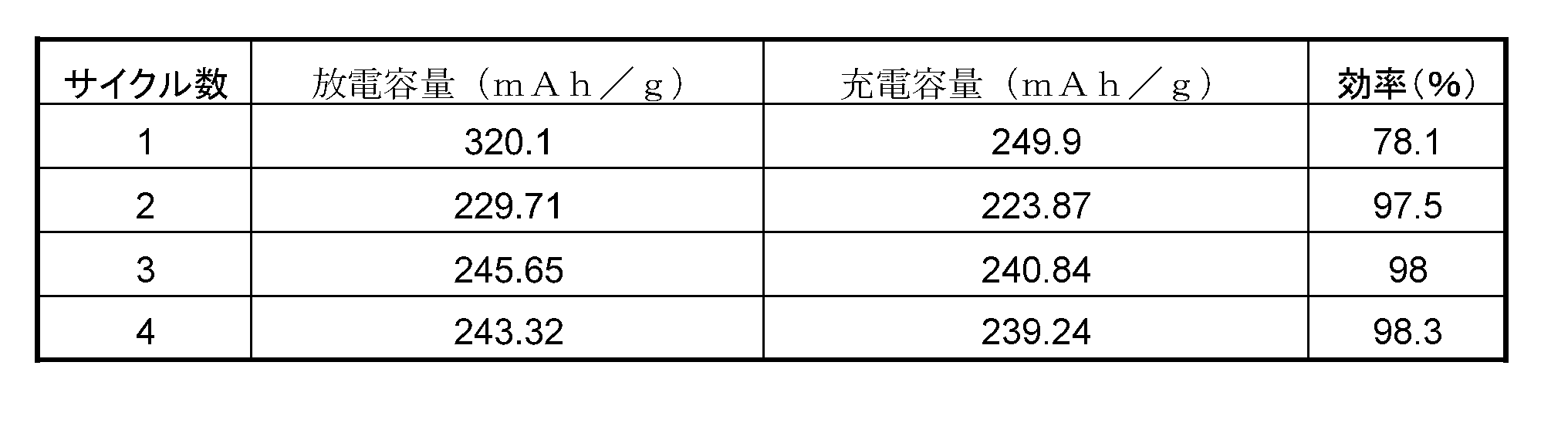
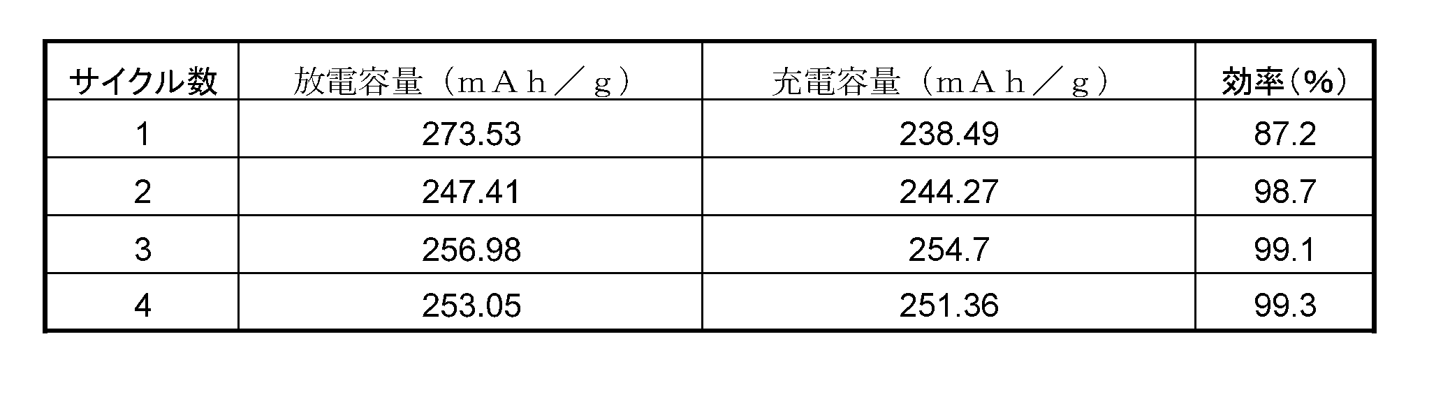
また、本実施形態のリチウムイオンボタン電池は、驚くべきことに、C/6レート(30時間の充電レート)と2Cレート(30分の充電レート)とでの充電容量が同じであることがわかった。ちなみに、MCMB電極を用いたリチウムイオンボタン電池の充電容量は、2Cレートでは、C/6レートの場合の88%しか得られなかった。
BET比表面積:約4.7m2/g~約390m2/g
結晶子サイズ:約10Å~約30Å
なお、表1の試料1~3は、それぞれ、900℃、1500℃、3000℃の焼成温度で焼成したものであることから、焼成温度によりBET比表面積が変化することも分かる。
(1)ヤシ殻活性炭(日本エンバイロケミカルズ社製の粒状白鷺WH2C8/32SS、Lot No M957)、
(2)カーボンブラック(旭カーボン社製のSUNBLACK285、Lot No 8BFS6)、
を用いた。
(b)イソプレン(ジェイエスアールクレイトンエラストマー社製のIR-2200)、
(c)ポリ塩化ビニル樹脂(新第一塩ビ社製のZEST1000Z、Lot No C60211)、
を用いた。
(1)エチレン・プロピレンジエンゴムを母材とした場合には、約400phrもの含有率が確認できた。
(1)イソプレンを母材とした場合には、約100phrの含有率が確認できた。ただし、この場合、この加圧成形体を湾曲させると、クラックが発生した。また、150phr以上練り込むのは不可能であった。
Claims (4)
- 大豆皮、菜種粕、コットンハル、胡麻、綿実のいずれかの焼成物を含む電池部品。
- 前記焼成体の内皮は、網目状の構造である、請求項1記載の電池部品。
- 請求項1記載の電池部品を備える電池。
- 前記電池部品は、正極活物質、負極活物質、又は、これらの間に位置するセパレータである電池。
Priority Applications (4)
| Application Number | Priority Date | Filing Date | Title |
|---|---|---|---|
| CN2009801379864A CN102165632A (zh) | 2008-09-29 | 2009-09-28 | 电池部件和电池 |
| EP09816242A EP2343759A4 (en) | 2008-09-29 | 2009-09-28 | BATTERY COMPONENT AND BATTERY |
| US13/121,258 US20110180749A1 (en) | 2008-09-29 | 2009-09-28 | Battery component and battery |
| JP2009541672A JPWO2010035828A1 (ja) | 2008-09-29 | 2009-09-28 | 電池部品及び電池 |
Applications Claiming Priority (6)
| Application Number | Priority Date | Filing Date | Title |
|---|---|---|---|
| JP2008-249851 | 2008-09-29 | ||
| JP2008249851 | 2008-09-29 | ||
| JP2008314945 | 2008-12-10 | ||
| JP2008-314945 | 2008-12-10 | ||
| JP2009181242 | 2009-08-04 | ||
| JP2009-181242 | 2009-08-04 |
Publications (1)
| Publication Number | Publication Date |
|---|---|
| WO2010035828A1 true WO2010035828A1 (ja) | 2010-04-01 |
Family
ID=42059821
Family Applications (1)
| Application Number | Title | Priority Date | Filing Date |
|---|---|---|---|
| PCT/JP2009/066777 WO2010035828A1 (ja) | 2008-09-29 | 2009-09-28 | 電池部品及び電池 |
Country Status (7)
| Country | Link |
|---|---|
| US (1) | US20110180749A1 (ja) |
| EP (1) | EP2343759A4 (ja) |
| JP (1) | JPWO2010035828A1 (ja) |
| KR (1) | KR20110054030A (ja) |
| CN (1) | CN102165632A (ja) |
| TW (1) | TW201025707A (ja) |
| WO (1) | WO2010035828A1 (ja) |
Cited By (3)
| Publication number | Priority date | Publication date | Assignee | Title |
|---|---|---|---|---|
| WO2014038491A1 (ja) * | 2012-09-06 | 2014-03-13 | 株式会社クレハ | 非水電解質二次電池負極用炭素質材料及びその製造方法 |
| WO2015011970A1 (ja) * | 2013-07-25 | 2015-01-29 | ソニー株式会社 | 電極材料及び二次電池 |
| KR102574545B1 (ko) * | 2023-01-17 | 2023-09-08 | (주) 매그나텍 | 커피박 조성물 및 이를 포함하는 이차전지용 음극재 |
Families Citing this family (5)
| Publication number | Priority date | Publication date | Assignee | Title |
|---|---|---|---|---|
| US8728353B2 (en) * | 2008-09-29 | 2014-05-20 | Asahi Organic Chemicals Industry Co., Ltd. | Burned plant material and electromagnetic shielding member |
| JP2014154225A (ja) * | 2013-02-05 | 2014-08-25 | Sony Corp | 電極材料、電極及び電池 |
| CN107958982B (zh) * | 2017-08-23 | 2023-08-04 | 湖南中锂新材料有限公司 | 用于锂离子动力电池的嵌合式复合隔膜及制备方法 |
| CN109734086A (zh) * | 2019-01-16 | 2019-05-10 | 广东工业大学 | 一种多孔结构碳材料及其制备方法和应用 |
| TWI751781B (zh) * | 2020-11-10 | 2022-01-01 | 國立清華大學 | 生物燃料電池 |
Citations (9)
| Publication number | Priority date | Publication date | Assignee | Title |
|---|---|---|---|---|
| WO1996027911A1 (en) * | 1995-03-06 | 1996-09-12 | Sony Corporation | Negative electrode material for secondary cell for nonaqueous electrolytic solution, process for the production thereof, and secondary cell for nonaqueous electrolytic solution using it |
| JPH08236116A (ja) * | 1994-12-16 | 1996-09-13 | Moli Energy 1990 Ltd | 黒鉛前駆体炭素質挿入化合物およびその再充電可能電池の負極としての使用 |
| JPH09161801A (ja) * | 1995-10-03 | 1997-06-20 | Kureha Chem Ind Co Ltd | 非水溶媒系二次電池の電極用炭素質材料及びその製造方法、並びに非水溶媒系二次電池 |
| JPH10101453A (ja) * | 1996-10-01 | 1998-04-21 | Sanwa Yushi Kk | 多孔性炭素材製品および硬質多孔性炭素材製品の製造方法 |
| JPH11283620A (ja) | 1998-03-30 | 1999-10-15 | Sony Corp | 非水電解液二次電池用負極炭素質材料の製造方法 |
| JP2000290662A (ja) * | 1999-04-02 | 2000-10-17 | Ebara Corp | 均質なミクロポアを有する多孔質炭の製造方法 |
| JP2004137144A (ja) * | 2002-09-27 | 2004-05-13 | Sanwa Yushi Kk | 多孔性炭素材、それを使った多孔性炭素材粉末、およびそれらの製造方法、ならびにそれら多孔性炭素材粉末を使った多孔性炭素材製品の製造方法 |
| JP2004220972A (ja) * | 2003-01-16 | 2004-08-05 | Hitachi Chem Co Ltd | リチウム二次電池負極用炭素材料及びその製造法、リチウム二次電池負極並びにリチウム二次電池 |
| JP2007134286A (ja) * | 2005-11-14 | 2007-05-31 | Hitachi Plant Technologies Ltd | リチウム二次電池用負極材料及びリチウム二次電池 |
Family Cites Families (10)
| Publication number | Priority date | Publication date | Assignee | Title |
|---|---|---|---|---|
| US3835064A (en) * | 1971-09-23 | 1974-09-10 | T Shinomiya | Process for manufacturing an activated carbon |
| US6537947B1 (en) * | 1997-04-11 | 2003-03-25 | The United States Of America As Represented By The Secretary Of Agriculture | Activated carbons from low-density agricultural waste |
| US6143268A (en) * | 1997-10-14 | 2000-11-07 | 3M Innovative Properties Company | Hydrocarbon treatment of carbonaceous materials |
| WO2004049473A2 (en) * | 2002-11-26 | 2004-06-10 | Showa Denko K.K. | Electrode material comprising silicon and/or tin particles and production method and use thereof |
| KR100751772B1 (ko) * | 2003-06-05 | 2007-08-23 | 쇼와 덴코 가부시키가이샤 | 배터리 전극용 탄소재료와 그 제조방법 및 용도 |
| US20070092428A1 (en) * | 2003-10-31 | 2007-04-26 | Showa Denko K.K. | Carbon material for battery electrode and production method and use thereof |
| US20050196336A1 (en) * | 2004-03-05 | 2005-09-08 | Chatterjee Arup K. | Activated graphitic carbon and metal hybrids thereof |
| US8728353B2 (en) * | 2008-09-29 | 2014-05-20 | Asahi Organic Chemicals Industry Co., Ltd. | Burned plant material and electromagnetic shielding member |
| US8318356B2 (en) * | 2008-12-15 | 2012-11-27 | Corning Incorporated | Activated carbon materials for high energy density ultracapacitors |
| KR101456905B1 (ko) * | 2010-02-19 | 2014-10-31 | 가부시키가이샤 인큐베이션 얼라이언스 | 탄소 재료 및 그 제조 방법 |
-
2009
- 2009-09-28 TW TW098132796A patent/TW201025707A/zh unknown
- 2009-09-28 WO PCT/JP2009/066777 patent/WO2010035828A1/ja active Application Filing
- 2009-09-28 US US13/121,258 patent/US20110180749A1/en not_active Abandoned
- 2009-09-28 KR KR1020117006991A patent/KR20110054030A/ko not_active Application Discontinuation
- 2009-09-28 JP JP2009541672A patent/JPWO2010035828A1/ja active Pending
- 2009-09-28 CN CN2009801379864A patent/CN102165632A/zh active Pending
- 2009-09-28 EP EP09816242A patent/EP2343759A4/en not_active Withdrawn
Patent Citations (9)
| Publication number | Priority date | Publication date | Assignee | Title |
|---|---|---|---|---|
| JPH08236116A (ja) * | 1994-12-16 | 1996-09-13 | Moli Energy 1990 Ltd | 黒鉛前駆体炭素質挿入化合物およびその再充電可能電池の負極としての使用 |
| WO1996027911A1 (en) * | 1995-03-06 | 1996-09-12 | Sony Corporation | Negative electrode material for secondary cell for nonaqueous electrolytic solution, process for the production thereof, and secondary cell for nonaqueous electrolytic solution using it |
| JPH09161801A (ja) * | 1995-10-03 | 1997-06-20 | Kureha Chem Ind Co Ltd | 非水溶媒系二次電池の電極用炭素質材料及びその製造方法、並びに非水溶媒系二次電池 |
| JPH10101453A (ja) * | 1996-10-01 | 1998-04-21 | Sanwa Yushi Kk | 多孔性炭素材製品および硬質多孔性炭素材製品の製造方法 |
| JPH11283620A (ja) | 1998-03-30 | 1999-10-15 | Sony Corp | 非水電解液二次電池用負極炭素質材料の製造方法 |
| JP2000290662A (ja) * | 1999-04-02 | 2000-10-17 | Ebara Corp | 均質なミクロポアを有する多孔質炭の製造方法 |
| JP2004137144A (ja) * | 2002-09-27 | 2004-05-13 | Sanwa Yushi Kk | 多孔性炭素材、それを使った多孔性炭素材粉末、およびそれらの製造方法、ならびにそれら多孔性炭素材粉末を使った多孔性炭素材製品の製造方法 |
| JP2004220972A (ja) * | 2003-01-16 | 2004-08-05 | Hitachi Chem Co Ltd | リチウム二次電池負極用炭素材料及びその製造法、リチウム二次電池負極並びにリチウム二次電池 |
| JP2007134286A (ja) * | 2005-11-14 | 2007-05-31 | Hitachi Plant Technologies Ltd | リチウム二次電池用負極材料及びリチウム二次電池 |
Non-Patent Citations (1)
| Title |
|---|
| See also references of EP2343759A4 |
Cited By (6)
| Publication number | Priority date | Publication date | Assignee | Title |
|---|---|---|---|---|
| WO2014038491A1 (ja) * | 2012-09-06 | 2014-03-13 | 株式会社クレハ | 非水電解質二次電池負極用炭素質材料及びその製造方法 |
| JPWO2014038491A1 (ja) * | 2012-09-06 | 2016-08-08 | 株式会社クレハ | 非水電解質二次電池負極用炭素質材料及びその製造方法 |
| WO2015011970A1 (ja) * | 2013-07-25 | 2015-01-29 | ソニー株式会社 | 電極材料及び二次電池 |
| JP2015026480A (ja) * | 2013-07-25 | 2015-02-05 | ソニー株式会社 | 電極材料及び二次電池 |
| US10290875B2 (en) | 2013-07-25 | 2019-05-14 | Murata Manufacturing Co., Ltd. | Electrode material and secondary cell |
| KR102574545B1 (ko) * | 2023-01-17 | 2023-09-08 | (주) 매그나텍 | 커피박 조성물 및 이를 포함하는 이차전지용 음극재 |
Also Published As
| Publication number | Publication date |
|---|---|
| CN102165632A (zh) | 2011-08-24 |
| TW201025707A (en) | 2010-07-01 |
| EP2343759A1 (en) | 2011-07-13 |
| US20110180749A1 (en) | 2011-07-28 |
| JPWO2010035828A1 (ja) | 2012-02-23 |
| EP2343759A4 (en) | 2012-05-30 |
| KR20110054030A (ko) | 2011-05-24 |
Similar Documents
| Publication | Publication Date | Title |
|---|---|---|
| WO2010035828A1 (ja) | 電池部品及び電池 | |
| EP3780169A1 (en) | Negative electrode for non-aqueous electrolyte secondary battery and non-aqueous electrolyte secondary battery | |
| EP3131143B1 (en) | Negative electrode material for lithium-ion secondary battery, method for manufacturing negative electrode material for lithium-ion secondary battery, negative electrode material slurry for lithium-ion secondary battery, negative electrode for lithium-ion secondary battery, and lithium-ion secondary battery | |
| EP2892096B1 (en) | Method for manufacturing a carbon material for nonaqueous electrolyte secondary battery | |
| JP5373388B2 (ja) | リチウムイオン二次電池用負極材料およびその製造方法 | |
| EP3026736A1 (en) | Anode active material for lithium secondary battery | |
| KR20090031421A (ko) | 리튬 이온 2차 전지용 음극 활물질 및 이를 포함한 음극 | |
| KR20170007140A (ko) | 혼합 흑연을 포함하는 음극 활물질, 이를 포함하는 음극 및 상기 음극을 이용한 리튬 이차전지 | |
| KR20130087609A (ko) | 리튬 이온 이차 전지용 부극재 및 그 제조 방법, 리튬 이온 이차 전지용 부극, 그리고 리튬 이온 이차 전지 | |
| JP6456474B2 (ja) | 非水電解質二次電池用混合負極材料の製造方法及びその製造方法によって得られる非水電解質二次電池用混合負極材料 | |
| EP3358656A1 (en) | Carbonaceous material for negative electrode of nonaqueous-electrolyte secondary battery, and process for producing same | |
| KR20170018208A (ko) | 이차전지용 음극 및 이의 제조방법 | |
| JP6759583B2 (ja) | リチウム二次電池用複合活物質およびその製造方法、リチウム二次電池 | |
| EP4287305A1 (en) | Negative electrode material for lithium-ion secondary battery, evaluation method therefor, manufacturing method therefor, negative electrode for lithium-ion secondary battery, and lithium-ion secondary battery | |
| KR101549321B1 (ko) | 2차 전지 및 2차 전지의 제조 방법 | |
| US20230084916A1 (en) | Negative electrode material for lithium-ion secondary battery and method of producing same, negative electrode for lithium-ion secondary battery, and lithium-ion secondary battery | |
| EP4109591A1 (en) | Anode, and secondary battery comprising anode | |
| EP3780182A1 (en) | Negative electrode material for lithium ion secondary battery, production method for negative electrode material for lithium ion secondary battery, negative electrode material slurry for lithium ion secondary battery, negative electrode for lithium ion secondary battery, and lithium ion secondary battery | |
| JP2015230794A (ja) | リチウムイオン二次電池用導電材料、リチウムイオン二次電池負極形成用組成物、リチウムイオン二次電池正極形成用組成物、リチウムイオン二次電池用負極、リチウムイオン二次電池用正極及びリチウムイオン二次電池 | |
| EP4027411A1 (en) | Negative electrode material for lithium ion secondary battery, method for manufacturing negative electrode material for lithium ion secondary battery, negative electrode material slurry for lithium ion secondary battery, negative electrode for lithium ion secondary battery, and lithium ion secondary battery | |
| JP2017016774A (ja) | リチウムイオン二次電池負極及び二次電池 | |
| EP2908366B1 (en) | Method for the production of a composite carbon particle | |
| KR102632742B1 (ko) | 탄소질 재료, 탄소질 재료의 제조 방법, 리튬 이온 2차 전지용 부극 및 리튬 이온 2차 전지 | |
| EP4254546A1 (en) | Composite particles for non-aqueous electrolyte rechargeable battery, producing method, positive and negative electrodes, and non-aqueous electrolyte rechargeable battery | |
| KR20240078312A (ko) | 리튬-황 전지용 양극 및 고에너지 밀도 특성을 갖는 리튬-황 전지 |
Legal Events
| Date | Code | Title | Description |
|---|---|---|---|
| WWE | Wipo information: entry into national phase |
Ref document number: 200980137986.4 Country of ref document: CN |
|
| WWE | Wipo information: entry into national phase |
Ref document number: 2009541672 Country of ref document: JP |
|
| 121 | Ep: the epo has been informed by wipo that ep was designated in this application |
Ref document number: 09816242 Country of ref document: EP Kind code of ref document: A1 |
|
| ENP | Entry into the national phase |
Ref document number: 20117006991 Country of ref document: KR Kind code of ref document: A |
|
| WWE | Wipo information: entry into national phase |
Ref document number: 13121258 Country of ref document: US |
|
| NENP | Non-entry into the national phase |
Ref country code: DE |
|
| WWE | Wipo information: entry into national phase |
Ref document number: 2009816242 Country of ref document: EP |