WO2010035693A1 - 携帯端末、携帯端末の制御方法、検知装置、検知装置の制御方法、携帯端末制御システム、携帯端末制御プログラム、検知装置制御プログラム、コンピュータ読み取り可能な記録媒体 - Google Patents
携帯端末、携帯端末の制御方法、検知装置、検知装置の制御方法、携帯端末制御システム、携帯端末制御プログラム、検知装置制御プログラム、コンピュータ読み取り可能な記録媒体 Download PDFInfo
- Publication number
- WO2010035693A1 WO2010035693A1 PCT/JP2009/066286 JP2009066286W WO2010035693A1 WO 2010035693 A1 WO2010035693 A1 WO 2010035693A1 JP 2009066286 W JP2009066286 W JP 2009066286W WO 2010035693 A1 WO2010035693 A1 WO 2010035693A1
- Authority
- WO
- WIPO (PCT)
- Prior art keywords
- state
- mobile terminal
- vehicle
- unit
- external device
- Prior art date
- Legal status (The legal status is an assumption and is not a legal conclusion. Google has not performed a legal analysis and makes no representation as to the accuracy of the status listed.)
- Ceased
Links
Images


Classifications
-
- H—ELECTRICITY
- H04—ELECTRIC COMMUNICATION TECHNIQUE
- H04M—TELEPHONIC COMMUNICATION
- H04M1/00—Substation equipment, e.g. for use by subscribers
- H04M1/60—Substation equipment, e.g. for use by subscribers including speech amplifiers
- H04M1/6033—Substation equipment, e.g. for use by subscribers including speech amplifiers for providing handsfree use or a loudspeaker mode in telephone sets
- H04M1/6041—Portable telephones adapted for handsfree use
- H04M1/6075—Portable telephones adapted for handsfree use adapted for handsfree use in a vehicle
- H04M1/6083—Portable telephones adapted for handsfree use adapted for handsfree use in a vehicle by interfacing with the vehicle audio system
- H04M1/6091—Portable telephones adapted for handsfree use adapted for handsfree use in a vehicle by interfacing with the vehicle audio system including a wireless interface
-
- H—ELECTRICITY
- H04—ELECTRIC COMMUNICATION TECHNIQUE
- H04W—WIRELESS COMMUNICATION NETWORKS
- H04W4/00—Services specially adapted for wireless communication networks; Facilities therefor
- H04W4/16—Communication-related supplementary services, e.g. call-transfer or call-hold
-
- H—ELECTRICITY
- H04—ELECTRIC COMMUNICATION TECHNIQUE
- H04M—TELEPHONIC COMMUNICATION
- H04M2250/00—Details of telephonic subscriber devices
- H04M2250/02—Details of telephonic subscriber devices including a Bluetooth interface
Definitions
- the present invention relates to a portable terminal capable of controlling the operation of the portable terminal in response to an incoming call from the portable telephone network, a portable terminal control method, a detection device, a detection device control method, a portable terminal control system, a portable terminal control program, and a detection device control.
- the present invention relates to a program and a computer-readable recording medium.
- the user of the mobile terminal can perform various communications such as telephone communication and e-mail communication with the mobile terminal even when walking or standing still within the communication area of the base station.
- some mobile terminals have a function for preventing the mobile terminal from taking care of an incoming call operation while driving a vehicle.
- Patent Document 2 discloses a technique for forcibly stopping a ringing tone when a driving operation is a heavy load on a driver at the time of an incoming call, and allowing the other party to be notified that a response cannot be made if necessary. Yes. Specifically, when a mobile phone receives an incoming call, it determines the load on the driver performing the driving operation from the output of the vehicle speed sensor, steering angle sensor, parking brake sensor, backlight sensor, etc. It is.
- Patent Document 3 discloses a technique for reliably suppressing the use of the mobile phone main body during operation by automatically switching the operation state of the mobile phone. Specifically, an apparatus is disclosed that starts control of an incoming operation of a mobile phone when it detects the start of a vehicle engine.
- Japanese Patent Publication Japanese Patent Laid-Open No. 11-252642 (published September 17, 1999)” Japanese Patent Publication “Japanese Patent Laid-Open No. 10-294965 (published Nov. 4, 1998)” Japanese Patent Publication “Japanese Patent Laid-Open No. 2001-197556 (published on July 19, 2001)”
- the present invention has been made in view of the above-described problems, and an object of the present invention is to control the operation of a mobile terminal in response to an incoming call from the mobile phone network in accordance with the state of an external device located in the vicinity.
- a mobile terminal includes a first communication unit that communicates with an external device by short-range communication, a second communication unit that communicates with a mobile phone network, and the first communication unit.
- State monitoring means for acquiring state information from the external apparatus, state determination means for determining the state of the external apparatus based on the state information acquired by the state monitoring means, and the second communication unit receives an incoming call.
- an operation control means for performing an operation at the time of incoming call, which is defined in advance for each state of the external device.
- the mobile terminal control method is a mobile terminal control method that communicates with a mobile phone network and communicates with an external device by short-range communication, and acquires state information from the external device.
- a state determination step for determining the state of the external device based on the state information acquired in the step, the state monitoring step, and when the incoming call is received from the mobile phone network, the state is defined in advance for each state of the external device.
- an operation control step for performing an operation when an incoming call is received.
- the mobile terminal can acquire the state information from the external device connected by short-range communication, and can determine the state of the external device based on the acquired state information. And since the operation at the time of incoming from the mobile phone network is predefined for each state of the external device, the external device determined based on the status information obtained from the external device when there is an incoming call from the mobile phone network It is possible to perform an incoming call operation according to the state of the call.
- the mobile terminal can control the operation for receiving an incoming call from the mobile phone network according to the state of the external device. For example, when the state of the external device is in a state where it is not possible (or undesirable) to receive a call at the mobile terminal in the vicinity (within a communicable range by short-range communication), the mobile terminal prohibits incoming calls, etc. It is possible to perform the operation.
- the external device only transmits data for the mobile terminal to determine the state of the external device, and does not transmit data for specifying an operation when receiving from the mobile phone network to the mobile terminal. . Therefore, the operation according to the function of the own terminal can be selected by the determination of the portable terminal. Even when a new function is added to the mobile terminal, no response on the external device side is necessary.
- the “state of the external device” includes “the state of the external device itself” and “the situation where the external device is placed”. For example, as the “state of the external device itself”, when the external device is a vehicle and the external device itself that is a vehicle is traveling at a vehicle speed of 80 km / h, the external device is “running at a vehicle speed of 80 km / h” State "can be detected. Further, as the “situation where the external device is placed”, when the external device is mounted on the vehicle as an in-vehicle device and the vehicle is traveling at a vehicle speed of 80 km / h, the external device It is possible to detect a state of “installed in a vehicle traveling at / h”.
- short-range communication can employ short-range wireless communication such as Bluetooth (registered trademark) and infrared communication, but can also employ wired communication.
- the incoming call from the mobile phone network may be, for example, an incoming call, mail reception, message notification, or the like.
- contents of the operation at the time of incoming call for example, incoming call rejection, hands-free operation, silent, predetermined display, etc. are possible.
- the mobile terminal it is desirable to store in advance a definition of the operation at the time of incoming call according to the state of the external device in the storage unit as an operation content table. Furthermore, it is preferable that the mobile terminal user has a configuration for setting the operation at the time of incoming call according to the state of the external device.
- the portable terminal of the present invention is further characterized by further comprising first notification means for notifying the external device of the contents of the operation at the time of incoming call performed by the operation control means via the first communication unit. .
- the mobile terminal can further notify the external device of the content of the incoming call operation performed according to the state of the external device when receiving a call from the mobile phone network. Therefore, there is an effect that the content of the operation performed by the mobile terminal according to the state of the external device at the time of incoming call can be notified in the external device.
- the mobile terminal when the state of the external device is in the vicinity (within a communication range by short-range communication) where the mobile terminal cannot receive (or is not desirable), the mobile terminal receives an incoming call when receiving an incoming call.
- the contents of the operation can be notified to the user by, for example, screen display, audio output, vibration operation, or the like in the external device.
- the first notification unit when the state monitoring unit detects a change in the state of the external device, performs an operation performed by the operation control unit when receiving an incoming call in the state after the change. Is sent to the external device via the first communication unit.
- the mobile terminal when the mobile terminal detects that the status of the external device has changed based on the status information acquired from the external device, the mobile terminal performs the contents of the operation to be performed when receiving an incoming call from the mobile phone network. Information to be shown can be notified to the external device. Therefore, there is an effect that the external device can notify the content of the operation at the time of the incoming call that is performed when the mobile terminal receives an incoming call until the state of the external device next changes.
- the mobile terminal when the state of the external device changes to a state where it is not possible (or undesirable) to receive a call at the mobile terminal in the vicinity thereof (within a communication range by short-range communication), the mobile terminal When an incoming call is received, it is decided to perform an operation of rejecting the incoming call, and a notification to that effect is sent to the external device, and the external device can be notified by, for example, screen display, audio output, vibration operation, or the like.
- the portable terminal of the present invention further includes second notification means for notifying information indicating the state of the external device to the caller of the incoming call when the second communication unit receives the incoming call. It is a feature.
- the mobile terminal when the mobile terminal receives an incoming call from the mobile phone network, the mobile terminal performs an operation at the time of the incoming call according to the state of the external apparatus determined based on the state information acquired from the external apparatus. . Then, the information indicating the state of the external device can be notified to the caller of the incoming call.
- the “information indicating the status of the external device notified to the caller of the incoming call” may be the status information itself acquired from the external device so that the mobile terminal can determine the status of the external device.
- the information may be information acquired from the external device simultaneously with or separately from the state information, or may be information newly generated in the mobile terminal using data acquired from the external device.
- the external device is a car navigation system and the mobile terminal rejects an incoming call
- the current position and destination arrival time are received as “information indicating the state of the external device”. If the caller is notified, the caller of the incoming call can know when to make a call again.
- the operation control unit displays the content of the operation performed at the time of incoming call.
- the communication unit is set to a state before connection to the external device.
- the mobile terminal when the mobile terminal detects the disconnection of communication with the external device, the mobile terminal sets the content of the operation to be performed at the time of the incoming call from the mobile phone network to the state before the connection with the external device. be able to.
- the mobile terminal moves away from the vicinity of the external device (within the communication range by short-range communication)
- the communication between the mobile terminal and the external device is disconnected. Therefore, when it is no longer necessary to determine the operation when the mobile phone receives an incoming call from the mobile phone network according to the state of the external device, it is possible to return (initialize) the state before connection to the external device. It becomes.
- the mobile phone is separated from the in-vehicle device when the user gets out of the vehicle.
- the mobile terminal can be automatically returned from the drive mode to a state before being connected to the external device, for example, the normal mode.
- the detection device of the present invention is a detection device to which a sensor that detects a state of a detection target is connected, and a first communication unit that communicates with a mobile terminal that communicates with a mobile phone network by short-range communication, and the first communication Status information transmitting means for transmitting status information indicating the status of the detection target acquired from the sensor to the mobile terminal via a unit, and when the mobile terminal receives an incoming call from the mobile phone network, based on the status information It is characterized by comprising mobile terminal state notifying means for receiving and notifying the contents of the performed operation from the mobile terminal via the first communication unit.
- control method of the detection device of the present invention is a control method of the detection device that is connected to a mobile terminal that communicates with a mobile phone network and is connected by a short-range communication with a sensor that detects a state of a detection target.
- a portable terminal state notifying step for receiving and notifying the contents from the portable terminal.
- the detection device transmits the state information indicating the state of the detection target acquired from the sensor that detects the state of the detection target to the mobile terminal through short-range communication, and the mobile terminal is connected to the mobile phone network.
- the mobile terminal When an incoming call is received from the mobile terminal, the contents of the operation performed based on the state information are received from the portable terminal by short-range communication and notified.
- the mobile terminal when the mobile terminal is located in the vicinity of the detection device, the mobile terminal can control the operation for incoming calls from the mobile phone network according to the state of the detection device.
- an in-vehicle device connected to a sensor for detecting the state of the vehicle, a heart rate / blood pressure measurement function, a step count measurement function, an exercise assist device with an acceleration sensor, etc. of the type worn on the body are applied. it can.
- the detection device only transmits data for the mobile terminal to determine the state of the detection target, and does not transmit data for specifying an operation upon arrival from the mobile phone network to the mobile terminal. Therefore, the operation according to the function of the own terminal can be selected by the determination of the portable terminal. And even if it is a case where a new function is added to a portable terminal, the response
- the detection device of the present invention is mounted on a vehicle, and the sensor is characterized in that the vehicle is a detection target.
- the detection device is further mounted on the vehicle, and the sensor targets the vehicle. For this reason, the detection apparatus can acquire the state of the vehicle from the sensor. Therefore, the detection device can transmit data for the mobile terminal to determine the state of the vehicle to the mobile terminal.
- the mobile terminal can perform an operation according to the state of the vehicle. As a result, it is possible to cause the mobile terminal to control the operation for the incoming call of the mobile terminal while the driver is driving the vehicle.
- the detection device as the in-vehicle device is a state indicating the state of the vehicle acquired from the sensor.
- examples of the sensor that detects the state of the vehicle include a parking brake sensor, a vehicle speed sensor, a back gear sensor, and the like.
- the mobile terminal control system of the present invention includes the above-described detection device and the above-described mobile terminal using the detection device as an external device.
- the portable terminal and the detection device may be realized by a computer.
- the portable terminal and the detection device are realized by a computer by operating the computer as the respective means.
- the control program for the portable terminal and the detection device to be executed and the computer-readable recording medium on which the control program is recorded also fall within the scope of the present invention.
- the mobile terminal includes the first communication unit that communicates with the external device by short-range communication, the second communication unit that communicates with the mobile phone network, and the external device via the first communication unit.
- the state monitoring means for acquiring the state information from the apparatus
- the state determination means for determining the state of the external device based on the state information acquired by the state monitoring means
- the second communication unit It is a structure provided with the operation control means which performs the operation
- the mobile terminal control method includes a state monitoring step for acquiring state information from an external device, and a state determination for determining the state of the external device based on the state information acquired in the state monitoring step. And an operation control step for performing an operation at the time of an incoming call, which is defined in advance for each state of the external device when an incoming call is received from a mobile phone network.
- the mobile terminal can control the operation for receiving an incoming call from the mobile phone network according to the state of the external device. For example, when the state of the external device is in a state where it is not possible (or undesirable) to receive a call at the mobile terminal in the vicinity (within a communicable range by short-range communication), the mobile terminal prohibits incoming calls, etc. It is possible to perform the operation.
- the detection device of the present invention shows a state of a detection target acquired from a sensor to the mobile terminal via the first communication unit, a first communication unit that communicates with a mobile terminal communicating with a mobile phone network by short-range communication.
- Status information transmitting means for transmitting status information, and the mobile terminal receiving the content of the operation performed based on the status information when receiving an incoming call from the mobile phone network via the first communication unit And it is the structure provided with the portable terminal state alerting
- control method of the detection device of the present invention includes a state information transmission step of transmitting state information indicating a detection target state acquired from a sensor to a mobile terminal, and when the mobile terminal receives an incoming call from the mobile phone network, A mobile terminal state informing step of receiving and notifying the contents of the operation performed based on the state information from the mobile terminal.
- the mobile terminal can control the operation for the incoming call from the mobile phone network according to the state of the detection device.
- the detection device is mounted on a vehicle and is an in-vehicle device connected to a sensor that detects the state of the vehicle, the vehicle is in a high-speed traveling state, and the driver cannot receive a call on the mobile terminal.
- the detection device can cause the portable terminal to perform an operation such as prohibiting an incoming call by transmitting state information indicating the state of the vehicle acquired from the sensor to the portable terminal. It is.
- FIG. 1 illustrates an embodiment of the present invention and is a block diagram illustrating a main configuration of a mobile terminal control system. It is explanatory drawing shown about the external appearance of the operation part of a portable terminal. It is a sequence diagram which illustrates the outline of the operation mode control process performed in a portable terminal control system. It is the flowchart which showed the flow of the operation mode control process performed in a portable terminal control system. It is explanatory drawing shown about the example of the operation mode setting screen in a portable terminal. 3 is a data table showing an example of information stored in an operation content table. It is explanatory drawing explaining the event classification and action content which can be set to an action content table.
- FIG. 11 is an explanatory diagram illustrating an example of a screen display when the content of the operation content notification received from the mobile terminal is displayed on the display unit in the in-vehicle device. It is explanatory drawing shown about the data layout of the information stored in operation
- movement execution notification. FIG. 11 is an explanatory diagram illustrating an example of a screen display when the contents of the operation execution notification received from the mobile terminal are displayed on the display unit in the in-vehicle device.
- FIGS. 1 to 17 An embodiment of the present invention will be described with reference to FIGS. 1 to 17 as follows.
- FIG. 1 is a block diagram showing a main configuration of the mobile terminal control system 1.
- the mobile terminal control system 1 includes a mobile terminal 100, an in-vehicle device (external device, detection device) 200, and a vehicle state sensor 300.
- mobile terminal 100 is assumed to be configured based on a normal mobile phone.
- the in-vehicle device 200 is assumed to be configured based on a normal car navigation device. Therefore, FIG. 1 shows only the main components for explaining the present invention and will be described below.
- the mobile terminal 100 is a device for communication and information processing that can be carried by the user.
- a typical example of the mobile terminal 100 is a mobile phone.
- the mobile terminal 100 can be connected to the mobile phone network T.
- the in-vehicle device 200 is mounted on a vehicle and connected to a vehicle state sensor 300 for detecting the state of the vehicle, and provides information on the state of the vehicle acquired from the vehicle state sensor 300.
- the in-vehicle device 200 can provide various other functions such as a car navigation function and a portable terminal connection function.
- the portable terminal 100 and the in-vehicle device 200 are connected by short-range wireless communication.
- short-range wireless communication between the mobile terminal 100 and the in-vehicle device 200 is performed by Bluetooth (registered trademark), and pairing between the mobile terminal 100 and the in-vehicle device 200 is performed. It is assumed that it has been completed in advance.
- the vehicle state sensor 300 includes a sensor for detecting various states of the vehicle, and is connected to the in-vehicle device 200.
- the in-vehicle device 200 and the vehicle state sensor 300 are connected by wire in the present embodiment.
- a standard such as USB (Universal Serial ⁇ Bus) or IEEE1394 can be used.
- the present invention is not limited to this, and it is also possible to adopt a Bluetooth (registered trademark) or a wireless communication method such as infrared communication.
- the portable terminal 100 includes a storage unit 110, a telephone network communication unit (second communication unit) 120, a vehicle state monitoring unit (state monitoring unit) 132, a state determination unit (state determination unit) 134, and a mode control unit ( Operation control means) 136, setting section 138, notification section (first notification section, second notification section) 140, short-range communication section (first communication section) 150, display section 152, speaker 154,
- the configuration includes a vibration unit 156 and an operation unit 160.
- the storage unit 110 stores various data and programs. Examples of the storage unit 110 include a program necessary for operating the vehicle state monitoring unit 132, the state determination unit 134, the mode control unit 136, the setting unit 138, and the notification unit 140, communication control data, and the like.
- ROM Read Only Memory
- RAM random access
- rewritable nonvolatile memory for example, flash memory
- the storage unit 110 stores an operation content table 112 for storing operation content corresponding to each event type. Details of the operation content storage table 112 will be described later.
- the telephone network communication unit 120 communicates with the mobile phone network T.
- the mobile phone network T is connected to a mobile phone (not shown) as a caller for making a call to the mobile terminal 100.
- the vehicle state monitoring unit 132 acquires vehicle state information (state information) indicating the vehicle state acquired from the vehicle state sensor 300 from the in-vehicle device 200 via the short-range communication unit 150.
- the state determination unit 134 determines the state of the in-vehicle device 200 based on the vehicle state information acquired by the vehicle state monitoring unit 132.
- the mode control unit 136 When the telephone network communication unit 120 receives an incoming call, the mode control unit 136 performs an incoming call operation that is predefined for each state of the in-vehicle device 200. In addition, when the vehicle state monitoring unit 132 detects the disconnection of the communication with the in-vehicle device 200 by the short-range communication unit 150, the mode control unit 136 uses the short-range communication unit 150 to indicate the content of the operation to be performed when the incoming call is received. Set to the state before connecting to.
- the setting unit 138 receives an input signal from the operation unit 160 and updates the operation content table based on the received input signal.
- the notification unit 140 controls notification of an operation performed in response to the occurrence of a communication event such as an incoming call in the telephone network communication unit 120.
- the notification unit 140 transmits information indicating the content of the operation performed by the mode control unit 136 when an incoming call is received in the state after the change. Notification is made to the portable terminal status notification unit 232 of the in-vehicle device 200 via the unit 150.
- the notification unit 140 displays information indicating that the state of the in-vehicle device 200 has changed and / or the content of the operation performed by the mode control unit 136 when receiving an incoming call in the state after the change.
- 152, the speaker 154, and the vibration unit 156 may be used for notification.
- the notification unit 140 Information indicating the state of the apparatus 200 is notified.
- the notification unit 140 uses the display unit 152, the speaker 154, and the vibration unit 156 to carry information indicating that the information indicating the state of the in-vehicle device 200 has been notified to the caller of the incoming call, and the notified content. Notification may be made at the terminal 100, or may be notified to the portable terminal state notification unit 232 of the in-vehicle device 200 via the short-range communication unit 150.
- the notification unit 140 receives communication in the telephone network communication unit 120 at a normal time when the mobile terminal 100 is not connected to the in-vehicle device 200 and is not linked to the in-vehicle device 200, for example, Control is performed so as to notify the speaker 154 and the vibration unit 156 that communication has been received.
- the notification unit 140 transmits screen data to the display unit 152 and controls screen display on the display unit 152.
- the notification unit 140 transmits audio data to the speaker 154 and controls audio output from the speaker 154.
- the notification unit 140 transmits a vibration control command to the vibration unit 156 and controls the vibration operation in the vibration unit 156.
- the near field communication unit 150 communicates with the in-vehicle device 200 by near field communication.
- the short-range communication unit 150 performs communication using Bluetooth (registered trademark).
- the present invention is not limited to this, and communication using a wireless communication standard such as ZigBee (registered trademark), UWB (Ultra Wide Band), or wireless LAN (IEEE 802.11) may be performed.
- the in-vehicle device 200 may be connected to perform communication.
- the display unit 152 displays an image on the display screen based on the screen data received from the notification unit 140.
- a display screen for realizing the display unit 152 an LCD (Liquid Crystal Display), a PDP (Plasma Display Panel), an EL (Electroluminescence) display, or the like can be used.
- the speaker 154 generates audio based on the audio data received from the notification unit 140 and presents auditory information to the user.
- the vibration unit 156 performs the vibration operation specified in the vibration control command received from the notification unit 140.
- the operation unit 160 is provided with a button / key for receiving an input operation from the user, and outputs an input signal corresponding to the button / key pressed by the user.
- the operation unit 160 is a general-purpose input device by the user of the mobile terminal 100, in the present embodiment, the operation unit 160 particularly sets the input signal generated based on the user's input operation to the setting unit 138. Send to.
- buttons / keys provided on the operation unit 160 will be described with reference to FIG.
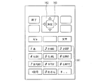
- FIG. 2 is an explanatory diagram showing the appearance of the operation unit 160 of the mobile terminal 100.
- buttons such as a numeric keypad 161, up / down / left / right buttons 162, and an enter button 163 are provided.
- the numeric keypad 161 is mainly used for inputting numbers and characters.
- the up / down / left / right button 162 is mainly used to move the cursor up / down / left / right when a menu or the like is selected.
- the enter button 163 is mainly used to confirm the item selected by the up / down / left / right button 162.
- the mobile terminal 100 may include a positioning device (position acquisition unit) such as a GPS (Global Positioning System) in order to acquire the current position of the terminal itself.
- a positioning device position acquisition unit
- GPS Global Positioning System
- the in-vehicle device 200 includes a storage unit 210, a short-range communication unit (first communication unit) 220, a portable terminal state notification unit (portable terminal state notification unit) 232, a portable terminal management unit 234, and a state data transmission unit ( (Status information transmission means) 236, a vehicle information acquisition unit 238, a position acquisition unit 240, a car navigation unit 250, a display unit 260, and a speaker 270.
- the in-vehicle device 200 is mounted on a vehicle, and a vehicle state sensor 300 (sensor) disposed on the vehicle is connected to detect the state of the vehicle.
- the storage unit 210 stores various data and programs. As an example of the storage unit 210, a program or communication control data required when each unit of the portable terminal state notification unit 232, the portable terminal management unit 234, the state data transmission unit 236, and the vehicle information acquisition unit 238 operates.
- ROM which is a read-only semiconductor memory that stores fixed data such as, RAM that serves as a working memory that temporarily stores data related to communication, data used for calculations, and calculation results, and various setting data And a rewritable nonvolatile memory (for example, a flash memory).
- the storage unit 210 stores a connection management table 212 for managing the mobile terminal 100 connected to the in-vehicle device 200.
- the connection management table 212 stores a Bluetooth address and a device name as terminal information of the paired mobile terminal 100.
- the near field communication unit 220 communicates with the mobile terminal 100 by near field communication.
- the short-range communication unit 220 performs communication using Bluetooth (registered trademark), similarly to the short-range communication unit 150 of the mobile terminal 100.
- Bluetooth registered trademark
- the present invention is not limited to this, and communication using a wireless communication standard such as ZigBee (registered trademark), UWB (Ultra Wide Band), and wireless LAN (IEEE 802.11) may be performed. 200 may be connected by wire to perform communication.
- the mobile terminal status notification unit 232 receives the content of the operation performed based on the vehicle status information from the mobile terminal 100 via the short-range communication unit 220 when the mobile terminal 100 receives an incoming call from the mobile phone network T, and notifies the mobile terminal status notification unit 232 To do.
- the mobile terminal management unit 234 manages the in-vehicle device 200 and the paired mobile terminal 100 connected to the in-vehicle device 200 using the connection management table 212. Details of the operation of the portable terminal management unit 234 will be described later.
- the state data transmission unit 236 reaches the mobile terminal 100 via the short-range communication unit 220, vehicle state information indicating the state of the vehicle acquired by the vehicle information acquisition unit 238 from the vehicle state sensor 300, and the current position and destination.
- the status data including information such as the expected time to be transmitted is transmitted.
- the vehicle information acquisition unit 238 is connected to the vehicle state sensor 300 for detecting the state of the vehicle, and receives a detection signal from the vehicle state sensor 300.
- the position acquisition unit 240 is for acquiring the current position of the vehicle.
- the position acquisition unit 240 can employ a positioning system such as GPS (Global Positioning System) to acquire the current position of the vehicle.
- GPS Global Positioning System
- the car navigation unit 250 searches the route from the current position of the vehicle to the destination by setting the destination, and presents the searched route to the user through the display unit 260 and the speaker 270.
- the display unit 260 receives screen data from the mobile terminal state notifying unit 232 and the car navigation unit 250 and displays the screen data.
- a display screen for realizing the display unit 260 an LCD (Liquid Crystal Display), a PDP (Plasma Display Panel), an EL (Electroluminescence) display, or the like can be used.
- the speaker 270 generates audio based on audio data received from the mobile terminal status notifying unit 232 and the car navigation unit 250 and presents auditory information to the user.
- the vehicle state sensor 300 includes various sensors for detecting the state of the vehicle. This sensor can be composed of, for example, a parking brake sensor, a vehicle speed sensor, and a back gear sensor.
- FIG. 3 is a sequence diagram illustrating an outline of an operation mode control process executed in the mobile terminal control system 1.
- the operation mode of the mobile terminal 100 is set in advance for each vehicle state (S101).
- the operation mode is set by the operation unit 160 receiving a user input, and the setting unit 138 storing the received input in the operation content table 112.
- the user's portable terminal 100 is searched from the in-vehicle device 200, and a connection request is transmitted to the portable terminal 100 (S151).
- the mobile terminal 100 receives the connection request transmitted from the in-vehicle device 200, accepts the connection, and enables the so-called drive mode function (S102).
- vehicle state information “current position”, and “estimated arrival time”, which are information on the state of the vehicle, are notified from the in-vehicle device 200 to the mobile terminal 100 (S152).
- vehicle state information specifically includes information obtained from a parking brake sensor, a vehicle speed sensor, and a back gear sensor included in the vehicle state sensor 300 connected to the in-vehicle device 200. Details of the vehicle state information will be described later.
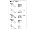
- the “vehicle state information” is analyzed and “running” is performed. And the state of the vehicle such as “stopped”. Then, the operation content corresponding to each vehicle state and the set operation mode, that is, the operation mode set for each vehicle state is set (S103). For example, when the vehicle state is “stopped”, the operation content is set so that the incoming call, the incoming mail, and the service notification are “normally incoming”.
- the mobile terminal 100 notifies the in-vehicle device 200 of the setting content, that is, the operation mode information (S104).
- the in-vehicle device 200 displays the content of the operation mode information on the display unit 260 (S153). In addition to displaying on the display unit 260, voice notification may be given to the user.
- the mobile terminal 100 performs control to limit various operations of the mobile terminal or disable operation according to the set operation mode (S105).
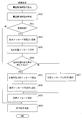
- FIG. 4 is a flowchart showing a flow of operation mode control processing executed in the mobile terminal control system 1.
- the portable terminal 100 accepts an operation mode setting operation at the operation unit 160. And the portable terminal 100 determines the presence or absence of operation mode setting operation (S201). At this time, if there is an operation mode setting operation (YES in S201), the mobile terminal 100 prompts the user to operate the operation unit 160 to set the operation mode in the drive mode (S202).
- FIG. 5 is an explanatory diagram showing an example of an operation mode setting screen in the mobile terminal 100.
- FIG. 6 is a data table showing an example of information stored in the operation content table 112.
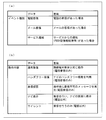
- FIG. 7 is an explanatory diagram illustrating event types and operation contents that can be set in the operation content table 112.
- the operation mode setting screen has a tab assigned to each vehicle state.
- the parking brake is raised and the vehicle is idling “when stopped”, the vehicle speed is zero, but the vehicle is idling and can start at any time (eg, waiting for a signal)
- the operation content can be set for each event type.
- event type includes a telephone call event indicating that a telephone call has been received, a mail incoming event indicating that a mail has been received, and a service notification indicating that there is a service notification which is a PUSH type information distribution means. There is an event.
- combo boxes corresponding to incoming calls, incoming emails, and service notifications are arranged, and the focus is moved up and down the cursor keys to receive incoming calls, incoming emails, and service notifications. Select the combo box. When the enter key is pressed, the combo box menu is expanded. The settable operation content can be further selected from this menu.
- a “normal incoming call” for performing a normal operation (setting state before connection to the in-vehicle device 200)
- a “hands-free incoming call” using a hands-free function provided by the in-vehicle device 200 and a message indicating that an incoming call cannot be transmitted “Reject incoming call”, “Navi display” for receiving an incoming call and displaying on the in-vehicle device 200, “Silent” for receiving an incoming call without notifying the user.
- the hands-free function is a function that allows the mobile terminal 100 to be operated by operating from an operation unit (not shown) of the in-vehicle device 200 without operating the mobile terminal 100. With this function, the operation of the mobile terminal 100 can be integrated with the operation of the in-vehicle device 200, so that safety during traveling can be improved.
- Each tab can be switched with the left and right keys. That is, when setting about each vehicle state, it should just switch to the tab of a desired vehicle state with a left-right key.
- the operation mode setting screen is provided with a “detailed setting for incoming call rejection” button, and when a call is rejected, a contact for permitting notification of the reason for rejection is individually set. You can also That is, when the “detailed call rejection setting” button is pressed, as shown in FIG. 5B, a contact to be notified of the reason for rejection when the call is rejected is displayed.
- the operation content set in (a) of FIG. 5 is stored as a table as shown in FIG. That is, for each vehicle state, it is possible to set the operation content at the time of incoming call, incoming mail, and service notification.
- the operation content is set for each event type.
- the operation content may be set in association with the relative positional relationship between the current position of the vehicle and the destination.
- the setting of “reject call” can be changed to the “hands-free call” setting within a range where there is no safety problem in driving the vehicle. it can. That is, it is possible to take measures to further ease the setting of the operation content as the destination is approached. By configuring in this way, it is possible to set operation contents that can flexibly respond to the user's request.
- the operation details may be set in association with the expected time of arrival at the destination. That is, if the destination arrives within 15 minutes, the “hands-free incoming call” setting can be changed to the “reject incoming call” setting. In other words, even if the mobile terminal 100 rejects the incoming call, it is sufficient to contact the caller 15 minutes later. By configuring in this way, it is possible to set operation contents that can flexibly respond to the user's request.
- portable terminal 100 accepts a connection request from in-vehicle device 200 in short-range communication unit 150.
- the connection request transmitted from the in-vehicle device 200 to the mobile terminal 100 includes a data item indicating a connection request of the Bluetooth standard as shown in FIG. Further, since this connection request is a connection request in the Bluetooth standard, further explanation is omitted here.
- the portable terminal 100 determines the presence or absence of the connection request from the vehicle-mounted apparatus 200 (S203). If there is no connection request from in-vehicle device 200 (NO in S203), portable terminal 100 continuously waits for a connection request (returns to S201). If there is a connection request from the in-vehicle device 200 (YES in S203), the mobile terminal 100 processes the connection request and shifts to the drive mode (S204).
- the mobile terminal management unit 234 specifies the mobile terminal 100 connected to the in-vehicle device 200 from the paired devices stored in the connection management table 212 (S250).
- the mobile terminal management unit 234 transmits a connection request to the mobile terminal 100 specified in S250 (S251).
- the portable terminal management unit 234 determines whether or not the connection request has been correctly transmitted (S252). If transmission of the connection request has failed (NO in S252), the portable terminal management unit 234 makes a connection request again (returns to S251) until the connection request is successful. On the other hand, if the transmission of the connection request is successful (YES in S252), the mobile terminal management unit 234 starts connection processing with the mobile terminal 100 in the short-range communication unit 220 (S253).
- the position acquisition unit 240 acquires the current position of the vehicle (S254). Then, the car navigation unit 250 determines whether or not a destination is set (S255). Here, when the destination is set (YES in S255), car navigation unit 250 searches for a route to the destination (S256). If the destination is not set (NO in S255), the process of S256 is omitted. Subsequently, the car navigation unit 250 updates the screen display on the display unit 260 based on the processing contents from S254 to S256 (S257). That is, the car navigation unit 250 displays the current position information acquired in S254 or the destination information and the route information searched in S256 on the display unit 260 when the destination is set.
- the vehicle state acquisition unit 238 acquires various vehicle state information indicating the state of the vehicle from the vehicle state sensor 300, analyzes the vehicle state information, and determines whether or not the vehicle state has changed ( S258). If the vehicle state has changed (YES in S258), vehicle state acquisition unit 238 transfers the vehicle state information to state data transmission unit 236. Then, the state data transmission unit 236 causes the car navigation unit 250 to calculate the required time to the current position and the destination, and acquires the required time from the car navigation unit 250 to the current position and the destination (S259).
- state data notification the information including the vehicle state information, the current position, and the required time to the destination is referred to as “state data notification”.
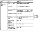
- FIG. 9 is an explanatory diagram showing the data layout of the information stored in the status data notification.
- the in-vehicle device 200 creates voice guidance corresponding to the current position and stores it in the item of current position voice.
- the current position voice stores voice guidance such as “Currently running near Nagaikecho, Abeno-ku, Osaka”.
- the time estimated to arrive at the destination is stored in the item of expected arrival time. For example, time information such as “14:30” is stored in the estimated destination arrival time.
- the voice guidance voice data corresponding to the predicted time of arrival at the destination is stored in the item of expected arrival time voice. For example, voice data “14:30” is stored in the destination arrival time expected voice. If no destination is set in the car navigation unit 250, blanks are set in the destination arrival time and destination arrival time sound items.
- various state information acquired from the vehicle state sensor 300 is stored. For example, a parking brake state indicating ON / OFF of a parking brake detected by a parking brake sensor, a vehicle speed sensor state indicating a vehicle speed (? Km / h) of a vehicle detected by a vehicle speed sensor, and a back gear detected by a back gear sensor. This is information such as the back gear sensor state indicating ON / OFF.
- the state data transmission unit 236 transmits state data notification including the vehicle state information, the current position, the required time to the destination, and the like to the mobile terminal 100 (S260; state information transmission step). If the vehicle state has not changed (NO in S258), the processes of S259 and S260 are omitted.
- the processes of S259 and S260 are performed according to the change of the vehicle state, but the processes of S259 and S260 are performed every predetermined time (for example, every minute) regardless of the change of the vehicle state. May be. In this case, this can be realized by determining the passage of the predetermined time in S258.
- the vehicle state monitoring unit 132 waits for a state data notification including vehicle state information transmitted from the in-vehicle device 200, and the state data is notified from the in-vehicle device 200. (S205; state monitoring step).
- the mode control unit 136 sets the operation content according to the vehicle state ( S206). Details of the processing in S206 (FIG. 14) will be described later.
- the mode control unit 136 transmits the set operation content as an operation content notification to the in-vehicle device 200 via the short-range communication unit 150 (S207). If vehicle state monitoring unit 132 determines that state data has not been notified from in-vehicle device 200 (NO in S205), the processes in S206 and S207 are omitted.
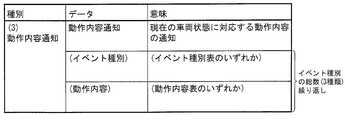
- FIG. 10 is an explanatory diagram showing the data layout of the information stored in the operation content notification.
- the operation content set for various event types is stored in the operation content notification. That is, the operation contents set for each of incoming telephone calls, incoming mails, and service notifications are stored.
- the in-vehicle device 200 determines whether an operation content notification has been received from the mobile terminal 100 (S261).
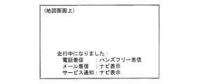
- the mobile terminal state notification unit 232 displays the content of the operation content notification on the display unit 260 (S262).
- the screen displayed on the display unit 260 is, for example, the screen shown in FIG. That is, the operation content may be displayed for each event type based on the received operation content notification from the mobile terminal 100.
- the state determination unit 134 monitors communication events such as incoming calls, incoming mails, and service notifications. When it is detected that these events have occurred (YES in S208), mode control unit 136 controls the operation of portable terminal 100 based on the operation content set for each vehicle state in accordance with the event that has occurred. (S209; operation control step). Details of the processing in S209 will be described later. Further, the state determination unit 134 causes the notification unit 140 to perform a notification operation according to the detected event. This notification operation is, for example, a screen display on the display unit 152, an audio output from the speaker 154, or a vibration in the vibration unit 156. At this time, if the notification is suppressed by setting the operation content, the notification unit 140 does not perform the notification operation.
- reporting part 140 notifies the vehicle-mounted apparatus 200 via the near field communication part 150 as content of alerting
- movement S210. If state determination unit 134 does not detect that an event has occurred (NO in S208), the processes in S209 and S210 are omitted.
- FIG. 12 is an explanatory diagram showing the data layout of the information stored in the operation execution notification.
- the operation execution notification corresponding to the event that occurred in the mobile terminal 100 is stored in the operation execution notification.
- “calling” is received at the mobile terminal 100 while “running”, in the case of the setting shown in FIG. 6, “hands-free incoming” is set as the operation content.
- An operation execution notification storing “call incoming” as the type and “hands-free incoming” as the executed operation is transmitted to the in-vehicle device 200.
- the portable terminal 100 detects whether communication is cut
- the portable terminal 100 repeats the processing from S205 to S211 again, and waits for notification of state data and occurrence of an event.
- the mobile terminal 100 initializes the operation content set as the operation mode (S212). That is, the drive mode is canceled, and the operation content is returned to the state before the in-vehicle device 200 is connected. Then, the mode shifts to a mode for performing a normal incoming call or the like, and again waits for a connection request from the in-vehicle device 200 (returns to S203).
- the in-vehicle device 200 determines whether or not an operation execution notification has been received from the mobile terminal 100 (S263).
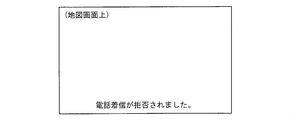
- the mobile terminal state notification unit 232 displays the content of the operation execution notification on the display unit 260 (S264; mobile) Terminal state notification step).
- the screen displayed on the display unit 260 is, for example, the screen shown in FIG. That is, the event type of the event that occurred in the mobile terminal 100 and the operation content corresponding to the event type may be displayed based on the received operation execution notification from the mobile terminal 100.
- the present invention is not limited to the screen display as shown in FIG. 13, and the above content may be notified by voice through the speaker 270.
- the in-vehicle device 200 determines whether or not the power is turned off (S265). If the power is not turned off (NO in S265), the in-vehicle device 200 further repeats the processing from S254 to S264. If the power is turned off (YES in S265), then in-vehicle device 200 ends the process in in-vehicle device 200.
- FIG. 14 is a flowchart showing a flow of operation content determination processing in the mobile terminal 100.
- the state determination unit 134 analyzes the vehicle state information included in the state data notification from the in-vehicle device 200 and determines the vehicle state (S60; state determination step). Details of the process in which the state determination unit 134 determines the vehicle state will be described later.
- the state determination unit 134 determines whether or not the vehicle state has changed as a result of determining the vehicle state (S61). Here, if the vehicle state does not change from the previous determination result (NO in S61), the operation content determination process is terminated without changing the operation content. If state determination unit 134 determines that the vehicle state has changed from the previous determination result (YES in S61), it stores the vehicle state in a temporary storage area (not shown) of storage unit 110 (S62).
- the mode control unit 136 starts control of the telephone network communication unit 120 based on the vehicle state and the operation content table 112 set in advance.
- the mode control unit 136 sets the operation at the time of incoming call according to the vehicle state (S63). The process in which the mode control unit 136 sets the operation at the time of incoming call according to the vehicle state will be described in detail later.
- the mode control unit 136 sets an operation for incoming mail (S64). Then, an operation for receiving a service notification is set (S65). Thereafter, the operation content determination process ends.
- FIG. 15 is a flowchart showing a flow of operation setting processing at the time of incoming call in the mobile terminal 100.
- the mode control unit 136 refers to the operation content stored in the operation content table 112 based on the vehicle state, and acquires the set operation content (S630). Then, the mode control unit 136 determines whether “incoming call rejection” is set (S631).
- mode control unit 136 stores the operation content setting in the temporary storage area of storage unit 110, and stores the operation content. Is determined (S639). Thereafter, the operation setting process at the time of incoming call ends.
- the mode control unit 136 assembles a voice message for responding to the caller.
- the mode control unit 136 adds the rejection message fixed form 1 (S632).
- the rejection message fixed phrase 1 is a message that informs that the user is unable to receive an incoming call, such as “cannot answer the call at present”.
- the mode control unit 136 adds a current position message.
- the mode control unit 136 assembles the current position message based on the current position information from the in-vehicle device 200.
- the current position message is, for example, a message indicating the current user position, such as “currently traveling near Nagaikecho, Abeno-ku, Osaka”.
- the mode control unit 136 determines whether or not the destination arrival prediction time voice is included in the state data notification received from the in-vehicle device 200 (S634).
- mode control unit 136 adds the destination arrival prediction time voice as an expected arrival time message (S635). That is, the voice data indicating the time such as “14:30” becomes the expected arrival time message.
- the required time to the destination may be in the form of time data that can be handled by a computer.
- the mode control unit 136 adds a rejection message template 2 (S636).
- the rejection message template 2 is a message following the expected arrival time message.
- the rejection message template 2 is composed of, for example, a message “Please call again later”. That is, the message “Please call again after 14:30” can be transmitted to the calling party by reproducing the rejection message template 2 following the expected arrival time message.
- a message indicating the required time such as “3 hours” is adopted, and a message “Please call again later” is adopted as the rejection message template 2, and a message indicating the required time is used.
- a message “Please call again in 3 hours” may be transmitted to the calling party through the rejection message template 2. That is, the timing for re-calling the call may be transmitted to the caller as a relative time.
- the mode control unit 136 adds the rejection message template 3 (S637).
- the rejection message template 3 simply notifies a message such as “Please try again”.
- the mode control unit 136 stores the voice message created in S636 or S637 in a temporary storage area (not shown) of the storage unit 110 (S638). Then, the mode control unit 136 stores the setting of the operation content “incoming call rejection” in the temporary storage area of the storage unit 110, and determines the operation content (S639). Thereafter, the operation setting process at the time of incoming call ends.
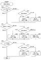
- FIG. 16 is a flowchart showing the flow of the vehicle state determination process in the mobile terminal 100.
- the vehicle state monitoring unit 132 When the vehicle state monitoring unit 132 receives the vehicle state information from the in-vehicle device 200, the vehicle state monitoring unit 132 analyzes the vehicle state information. Then, based on the analysis result, the vehicle state monitoring unit 132 determines the parking brake sensor state (S600). Here, if the vehicle state monitoring unit 132 determines that there is no change in the parking brake sensor state (no change in S600), the process proceeds to the next process. When it is determined that there is a change in the parking brake sensor state (there is a change in S600), the vehicle state monitoring unit 132 further determines the content of the change (S601).
- the vehicle state monitoring unit 132 determines that the vehicle state has changed to “still”. (S602). Further, when the content of the change in the parking brake sensor state is “OFF ⁇ ON” (OFF ⁇ ON in S601), the vehicle state monitoring unit 132 determines that the vehicle state has changed to “stopped”. Judgment is made (S603). Thus, after determining the content of the change in S602 and S603, the process proceeds to the next process.
- the vehicle state monitoring unit 132 determines the vehicle speed sensor state (S604). Here, if the vehicle state monitoring unit 132 determines that there is no change in the vehicle speed sensor state (no conversion in S604), the process proceeds to the next process. When it is determined that there is a change in the vehicle speed sensor state (change in S604), the vehicle state monitoring unit 132 further determines the content of the change (S605).
- the vehicle state monitoring unit 132 determines that the vehicle speed indicated by the vehicle speed sensor state has changed to 80 km / h or more (80 km / h or more in S605).
- the vehicle state monitoring unit 132 determines that the vehicle state has changed to “during high speed driving” (S606).
- the vehicle state monitoring unit 132 determines that the vehicle speed indicated by the vehicle speed sensor state has changed from 1 to 79 km / h (1 to 79 km / h in S605)
- the vehicle state monitoring unit 132 determines that the vehicle state has changed to “running”. (S607).
- the vehicle state monitoring unit 132 determines that the vehicle speed indicated by the vehicle speed sensor state has changed to 0 km / h (0 km / h in S605), the vehicle state monitoring unit 132 determines that the vehicle state has changed to “still” (S608). . Note that the vehicle state monitoring unit 132 may ignore the determination result when it is determined that the vehicle has moved backward. As described above, after determining the content of the change in S606 to S608, the process proceeds to the next process.
- the vehicle state monitoring unit 132 determines the back gear sensor state (S609). If the vehicle state monitoring unit 132 determines that there is no change in the back gear sensor state (no change in S609), the process proceeds to the next process. When it is determined that there is a change in the back gear sensor state (change in S609), the vehicle state monitoring unit 132 further determines the content of the change (S610).
- the vehicle state monitoring unit 132 determines that the vehicle state has changed to “still” when the content of the change in the back gear sensor state is “ON ⁇ OFF” (ON ⁇ OFF in S610). (S611). In addition, when the content of the change in the back gear sensor state is a change from “OFF ⁇ ON” (OFF ⁇ ON in S610), the vehicle state monitoring unit 132 determines that the vehicle state has changed to “reversing”. Judgment is made (S612). Thus, after determining the content of the change in S611 and S612, the process proceeds to the next process.
- the vehicle state monitoring unit 132 determines the vehicle state by determining the parking brake sensor state, the vehicle speed sensor state, and the back gear sensor state. Thereafter, the vehicle state determination process ends.
- the vehicle state determination process may be terminated without determining the next sensor state after determining the content of the change.
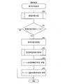
- FIG. 17 is a flowchart showing the flow of event-specific operation processing in the mobile terminal 100.
- the state determination unit 134 determines whether there is an incoming call event in the mobile terminal 100 (S90). That is, the state determination unit 134 determines whether the telephone network communication unit 120 has received communication from another mobile terminal via the mobile phone network T.
- state determination unit 134 determines that there is no incoming call in portable terminal 100 (NO in S90)
- the process proceeds to the next process.
- the state determination unit 134 determines whether or not the operation content is “reject incoming call” (S91).
- the state determination unit 134 acquires address information for specifying the transmission source, and based on the address information, an allowed address list (storage unit) that is a list of addresses that are permitted to notify the current location message. It is stored in 110. (not shown). Then, the state determination unit 134 determines whether or not the address information is permitted as a target for notifying the current position message (S92). That is, when the operation content is set to “reject call” for the incoming call event, the state determination unit 134 transmits the response voice message set in the operation setting for incoming call to the caller. The sender from which the determination unit 134 transmits a message can be specified in advance. This is because the voice message includes so-called personal information such as the current location and the destination of the user of the mobile terminal 100.
- the state determination unit 134 determines that the address information is not included in the permitted address list, that is, an address that is not permitted (YES in S92)
- the state determination unit 134 notifies the sender of the current location message. It is determined to be inappropriate, and the voice message is replaced (S93).
- the replacement voice message is, for example, “I cannot answer the phone now. Please try again”.
- the mode control unit 136 refers to the operation content table 112 and controls the telephone network communication unit 120 to execute the operation set as the operation content (S94).
- the state determination unit 134 sets the operation upon incoming call. Use the voice message as it is without replacing it. Then, the mode control unit 136 refers to the operation content table 112 and controls the telephone network communication unit 120 to execute the operation set as the operation content (S94).
- the state determination unit 134 determines the presence / absence of an incoming mail event after determining the presence / absence of an incoming call event in the mobile terminal 100 (S95). If state determining unit 134 determines that there is no mail incoming event in portable terminal 100 (NO in S95), it proceeds to the next process.
- mode control unit 136 refers to operation content table 112 and performs telephone network communication so as to execute the operation set as the operation content.
- the unit 120 is controlled (S96).
- the state determination unit 134 determines the presence / absence of a service notification event after determining the presence / absence of a mail incoming event in the mobile terminal 100 (S97).
- the state determination unit 134 ends the event-specific operation process. If state determining unit 134 determines that there is a service notification event (YES in S97), mode control unit 136 refers to operation content table 112 and performs telephone network communication so as to execute the operation set as the operation content.
- the unit 120 is controlled (S98). Thereafter, the event-specific operation process is terminated.
- the state determination unit 134 determines the presence / absence of each event of incoming call, incoming mail, and service notification in the event-specific operation processing.
- the mobile terminal control system 1 is composed of the mobile terminal 100, the in-vehicle device 200, and the vehicle state sensor 300. That is, a mobile terminal control system using a mobile terminal and an in-vehicle device as an external device has been described.
- the present invention is not limited to this, while the state of the external device is transmitted to the mobile terminal by communication means, and the mobile terminal is also used in combination with the external device that receives the operation content from the mobile terminal and performs notification by display, voice, vibration, etc.
- a control system can be configured.
- a television receiver (hereinafter referred to as a television) can be adopted as the external device.
- a mobile terminal control system When a mobile terminal control system is configured with a TV and a mobile terminal, if the TV energization status is received and it is determined that it is in a standby state, “normal incoming” is set as the operation content, and if the screen is displayed, Set “Reject incoming call” in the operation details. Then, it is possible to send the operation content to the television for display and present it to the user.
- a heating device such as a cooking utensil or a water heater can be used.
- a portable terminal control system is configured with such a thermal device and a portable terminal, the heat generation state is received by the cellular phone, and the state of the thermal device is determined by the cellular phone. That is, when it is determined that the temperature is low, “normal incoming call” is set as the operation content, and when it is determined that the ignition (heat generation) state is set, “reject incoming call” is set as the operation content. Then, it is possible to perform operations such as transmitting these operation contents to these appliances and notifying the user by voice.
- a heart-fitting / blood-pressure measuring function of the type worn on the body, a step count measuring function, an exercise assisting device with an acceleration sensor (such as a wristwatch) can be used as an external device.
- a mobile terminal control system is configured with such an exercise assistance device and a portable terminal
- information such as heart rate, blood pressure, steps per unit time, or exercise amount measured by the exercise assistance device is received by the portable terminal.
- “normal incoming” is set as the operation content, Set “Reject incoming call” in the operation details. Then, these operation contents can be transmitted to the exercise assisting device, and the user can be notified of the operation of the mobile phone by vibration or the like.
- each block of the mobile terminal 100 and the in-vehicle device 200 of the mobile terminal control system 1 in particular, the vehicle state monitoring unit 132, the state determination unit 134, the mode control unit 136, the notification unit 140, and the in-vehicle device of the mobile terminal 100.
- the 200 mobile terminal state notification unit 232, the mobile terminal management unit 234, and the state data transmission unit 236 may be configured by hardware logic, or may be realized by software using a CPU as follows.
- the mobile terminal 100 includes a CPU (central processing unit) that executes instructions of a control program that realizes each function, a ROM (read only memory) that stores the program, a RAM (random access memory) that expands the program,
- a storage device (recording medium) such as a memory for storing the program and various data is provided.
- the object of the present invention is to record the program code (execution format program, intermediate code program, source program) of the control program for the portable terminal 100 and the in-vehicle device 200, which is software that realizes the above-described functions, in a computer-readable manner. This can also be achieved by supplying the recording medium to the portable terminal 100 and the in-vehicle device 200 and reading and executing the program code recorded on the recording medium by the computer (or CPU or MPU).
- Examples of the recording medium include tapes such as magnetic tapes and cassette tapes, magnetic disks such as floppy (registered trademark) disks / hard disks, and disks including optical disks such as CD-ROM / MO / MD / DVD / CD-R.
- Card system such as IC card, IC card (including memory card) / optical card, or semiconductor memory system such as mask ROM / EPROM / EEPROM / flash ROM.
- the mobile terminal 100 and the in-vehicle device 200 may be configured to be connectable to a communication network, and the program code may be supplied via the communication network.
- the communication network is not particularly limited.
- the Internet intranet, extranet, LAN, ISDN, VAN, CATV communication network, virtual private network, telephone line network, mobile communication network, satellite communication. A net or the like is available.
- the transmission medium constituting the communication network is not particularly limited.
- infrared rays such as IrDA and remote control, Bluetooth ( (Registered trademark), 802.11 wireless, HDR, mobile phone network, satellite line, terrestrial digital network, and the like can also be used.
- the present invention can also be realized in the form of a computer data signal embedded in a carrier wave in which the program code is embodied by electronic transmission.
- the operation of the mobile terminal in response to an incoming call from the mobile phone network can be controlled in the mobile terminal according to the state of the external device located in the vicinity, the mobile terminal and an external device that can capture the user's state, for example, Since the portable terminal control system can be constructed in combination with a car navigation device or an exercise assistance device having a sensor such as a heart rate / blood pressure measurement function of the type worn on the body, it can be applied to various applications.
- Mobile terminal control system 100 Mobile terminal 120 Telephone network communication unit (second communication unit) 132 Vehicle status monitoring unit (status monitoring means) 134 State determination unit (state determination means) 136 Mode control unit (operation control means) 140 Notification unit (first notification unit, second notification unit) 150 Near Field Communication Department (First Communication Department) 200 In-vehicle device (external device) 220 Short-range communication unit (first communication unit) 232 portable terminal state notifying unit (portable terminal state notifying means) 236 Status data transmission unit (status information transmission means) 300 Vehicle state sensor (sensor) T mobile phone network
Landscapes
- Engineering & Computer Science (AREA)
- Computer Networks & Wireless Communication (AREA)
- Signal Processing (AREA)
- Multimedia (AREA)
- Telephone Function (AREA)
- Mobile Radio Communication Systems (AREA)
Applications Claiming Priority (2)
| Application Number | Priority Date | Filing Date | Title |
|---|---|---|---|
| JP2008-249001 | 2008-09-26 | ||
| JP2008249001A JP2010081419A (ja) | 2008-09-26 | 2008-09-26 | 携帯端末、携帯端末の制御方法、検知装置、検知装置の制御方法、携帯端末制御システム、携帯端末制御プログラム、検知装置制御プログラム、コンピュータ読み取り可能な記録媒体 |
Publications (1)
| Publication Number | Publication Date |
|---|---|
| WO2010035693A1 true WO2010035693A1 (ja) | 2010-04-01 |
Family
ID=42059693
Family Applications (1)
| Application Number | Title | Priority Date | Filing Date |
|---|---|---|---|
| PCT/JP2009/066286 Ceased WO2010035693A1 (ja) | 2008-09-26 | 2009-09-17 | 携帯端末、携帯端末の制御方法、検知装置、検知装置の制御方法、携帯端末制御システム、携帯端末制御プログラム、検知装置制御プログラム、コンピュータ読み取り可能な記録媒体 |
Country Status (2)
| Country | Link |
|---|---|
| JP (1) | JP2010081419A (enExample) |
| WO (1) | WO2010035693A1 (enExample) |
Cited By (2)
| Publication number | Priority date | Publication date | Assignee | Title |
|---|---|---|---|---|
| CN104041064A (zh) * | 2011-10-05 | 2014-09-10 | 高通股份有限公司 | 无线显示设备的最小认知模式 |
| CN116546129A (zh) * | 2023-03-29 | 2023-08-04 | 武汉星纪魅族科技有限公司 | 控制方法、电子设备和存储介质 |
Families Citing this family (9)
| Publication number | Priority date | Publication date | Assignee | Title |
|---|---|---|---|---|
| JP5656442B2 (ja) * | 2010-04-14 | 2015-01-21 | 株式会社デンソー | 車載通信システム |
| WO2011160679A1 (en) * | 2010-06-22 | 2011-12-29 | Tomtom International B.V. | Navigation device & method |
| JP5585545B2 (ja) * | 2011-06-28 | 2014-09-10 | 株式会社デンソー | 近距離通信システム、車両用機器および携帯通信端末 |
| JP5850223B2 (ja) * | 2011-08-06 | 2016-02-03 | 日本精機株式会社 | 車両用情報提供装置 |
| KR101860024B1 (ko) | 2011-09-26 | 2018-05-23 | 삼성전자 주식회사 | 차량 기반 통신 서비스 포워딩 방법 및 시스템과 이를 지원하는 단말기 |
| KR102004984B1 (ko) * | 2011-12-06 | 2019-10-02 | 삼성전자주식회사 | 모바일 단말을 이용한 차량 관리 시스템 및 방법 |
| US8811938B2 (en) * | 2011-12-16 | 2014-08-19 | Microsoft Corporation | Providing a user interface experience based on inferred vehicle state |
| WO2015098215A1 (ja) * | 2013-12-24 | 2015-07-02 | ソニー株式会社 | 情報処理装置、情報処理方法、プログラム、および情報処理システム |
| JP7589916B2 (ja) * | 2021-04-23 | 2024-11-26 | 株式会社スマートドライブ | 通信制御方法、通信制御装置、移動体及びプログラム |
Citations (5)
| Publication number | Priority date | Publication date | Assignee | Title |
|---|---|---|---|---|
| JPH11331417A (ja) * | 1998-05-19 | 1999-11-30 | Honda Motor Co Ltd | ナビゲーション装置 |
| JP2000091980A (ja) * | 1998-09-14 | 2000-03-31 | Nec Corp | 携帯電話機及び自動車システム |
| JP2004078100A (ja) * | 2002-08-22 | 2004-03-11 | Denso Corp | 音声出力制御システムおよびコンピュータプログラム |
| JP2005026802A (ja) * | 2003-06-30 | 2005-01-27 | Nec Corp | 携帯電話端末の着信制限システム |
| JP2006319727A (ja) * | 2005-05-13 | 2006-11-24 | Nec Infrontia Corp | 携帯端末モード設定システム、自動車車載用装置、携帯端末、携帯端末モード設定方法 |
Family Cites Families (3)
| Publication number | Priority date | Publication date | Assignee | Title |
|---|---|---|---|---|
| JP2003051896A (ja) * | 2001-05-28 | 2003-02-21 | Matsushita Electric Ind Co Ltd | 車載用通信装置及びその方法 |
| JP2003069698A (ja) * | 2001-08-22 | 2003-03-07 | Yamaha Corp | 携帯電話装置 |
| JP2007013931A (ja) * | 2005-05-30 | 2007-01-18 | Denso Corp | 車載通信装置および車載通信装置用プログラム |
-
2008
- 2008-09-26 JP JP2008249001A patent/JP2010081419A/ja active Pending
-
2009
- 2009-09-17 WO PCT/JP2009/066286 patent/WO2010035693A1/ja not_active Ceased
Patent Citations (5)
| Publication number | Priority date | Publication date | Assignee | Title |
|---|---|---|---|---|
| JPH11331417A (ja) * | 1998-05-19 | 1999-11-30 | Honda Motor Co Ltd | ナビゲーション装置 |
| JP2000091980A (ja) * | 1998-09-14 | 2000-03-31 | Nec Corp | 携帯電話機及び自動車システム |
| JP2004078100A (ja) * | 2002-08-22 | 2004-03-11 | Denso Corp | 音声出力制御システムおよびコンピュータプログラム |
| JP2005026802A (ja) * | 2003-06-30 | 2005-01-27 | Nec Corp | 携帯電話端末の着信制限システム |
| JP2006319727A (ja) * | 2005-05-13 | 2006-11-24 | Nec Infrontia Corp | 携帯端末モード設定システム、自動車車載用装置、携帯端末、携帯端末モード設定方法 |
Cited By (4)
| Publication number | Priority date | Publication date | Assignee | Title |
|---|---|---|---|---|
| CN104041064A (zh) * | 2011-10-05 | 2014-09-10 | 高通股份有限公司 | 无线显示设备的最小认知模式 |
| JP2014532367A (ja) * | 2011-10-05 | 2014-12-04 | クゥアルコム・インコーポレイテッドQualcomm Incorporated | ワイヤレスディスプレイデバイスのための最小認識モード |
| CN116546129A (zh) * | 2023-03-29 | 2023-08-04 | 武汉星纪魅族科技有限公司 | 控制方法、电子设备和存储介质 |
| CN116546129B (zh) * | 2023-03-29 | 2025-04-08 | 武汉星纪魅族科技有限公司 | 控制方法、电子设备和存储介质 |
Also Published As
| Publication number | Publication date |
|---|---|
| JP2010081419A (ja) | 2010-04-08 |
Similar Documents
| Publication | Publication Date | Title |
|---|---|---|
| WO2010035693A1 (ja) | 携帯端末、携帯端末の制御方法、検知装置、検知装置の制御方法、携帯端末制御システム、携帯端末制御プログラム、検知装置制御プログラム、コンピュータ読み取り可能な記録媒体 | |
| US9474103B2 (en) | Portable information terminal, a control method for a portable information terminal, a program of a method of controlling a personal information terminal and a recording medium having recorded therein a program of a method of controlling a personal information terminal | |
| EP2782297B1 (en) | Method and apparatus for providing state information | |
| US9467543B2 (en) | Electronic apparatus and electronic system | |
| US8254900B2 (en) | In-vehicle apparatus, cellular phone device, and method for controlling communication therebetween | |
| US20070081506A1 (en) | On-vehicle device | |
| US8131323B2 (en) | Handsfree apparatus | |
| CN108702416B (zh) | 用于在操作车辆的同时管理其操作的电子设备和方法 | |
| CN102883036A (zh) | 显示装置、移动通信终端和显示系统 | |
| CN104950728A (zh) | 平衡车管理方法及装置 | |
| JP2014202517A (ja) | 情報表示装置および情報表示方法 | |
| CN108712561A (zh) | 权限管理方法、装置、移动终端以及存储介质 | |
| US20100323673A1 (en) | Method for connecting and blocking call in portable terminal | |
| CN108632460A (zh) | 权限管理方法、装置、移动终端以及存储介质 | |
| CN104767860A (zh) | 来电提示方法、装置及终端 | |
| US8126514B2 (en) | In-vehicle apparatus, cellular phone device, and method for controlling communication therebetween | |
| CN106657645A (zh) | 呼叫请求处理方法与装置、呼叫方法与装置及相关终端 | |
| KR20090039688A (ko) | 개인 영역 네트워크 내에서 동작하는 이동국 | |
| CN107172604B (zh) | 呼叫处理方法、装置及终端电子设备 | |
| JP2006303584A (ja) | 携帯電話機から遠隔操作コマンドを受信する車載用受信装置、車載用受信装置用プログラム、携帯電話機、および携帯電話機用プログラム。 | |
| JP2003264875A (ja) | 移動通信端末および通信システム | |
| JP2011232872A (ja) | 緊急通報システムおよび緊急通報方法 | |
| JP2011234218A (ja) | 車両用の無線通信システム、車載装置、携帯通信端末、および車両用の無線通信方法 | |
| JP6250918B2 (ja) | 携帯電子機器、位置確認方法、及び位置確認プログラム | |
| CN105430170A (zh) | 消息同步方法及装置、电子设备 |
Legal Events
| Date | Code | Title | Description |
|---|---|---|---|
| 121 | Ep: the epo has been informed by wipo that ep was designated in this application |
Ref document number: 09816108 Country of ref document: EP Kind code of ref document: A1 |
|
| NENP | Non-entry into the national phase |
Ref country code: DE |
|
| 122 | Ep: pct application non-entry in european phase |
Ref document number: 09816108 Country of ref document: EP Kind code of ref document: A1 |