WO2010032372A1 - ネットワーク経路探索装置、方法及びプログラム - Google Patents
ネットワーク経路探索装置、方法及びプログラム Download PDFInfo
- Publication number
- WO2010032372A1 WO2010032372A1 PCT/JP2009/003901 JP2009003901W WO2010032372A1 WO 2010032372 A1 WO2010032372 A1 WO 2010032372A1 JP 2009003901 W JP2009003901 W JP 2009003901W WO 2010032372 A1 WO2010032372 A1 WO 2010032372A1
- Authority
- WO
- WIPO (PCT)
- Prior art keywords
- link
- node
- connection destination
- cost
- route
- Prior art date
- Legal status (The legal status is an assumption and is not a legal conclusion. Google has not performed a legal analysis and makes no representation as to the accuracy of the status listed.)
- Ceased
Links
Images


Classifications
-
- G—PHYSICS
- G01—MEASURING; TESTING
- G01C—MEASURING DISTANCES, LEVELS OR BEARINGS; SURVEYING; NAVIGATION; GYROSCOPIC INSTRUMENTS; PHOTOGRAMMETRY OR VIDEOGRAMMETRY
- G01C21/00—Navigation; Navigational instruments not provided for in groups G01C1/00 - G01C19/00
- G01C21/26—Navigation; Navigational instruments not provided for in groups G01C1/00 - G01C19/00 specially adapted for navigation in a road network
- G01C21/34—Route searching; Route guidance
- G01C21/3446—Details of route searching algorithms, e.g. Dijkstra, A*, arc-flags or using precalculated routes
Definitions
- the present invention relates to a network route search apparatus, method, and program, and more particularly, to a network route search device, method, and program based on a new data structure that represents a network, and a method for creating a new data structure that represents a network.
- a physical network such as a road network, a communication network, or a piping network is expressed by a logical network, and an optimal route is calculated on a computer and a delivery cost is calculated.
- a vehicle travel guidance device to which such network-related technology is applied is disclosed in Patent Document 1 below.
- a network in a conventional logical network (hereinafter simply referred to as a network), as described in Tables 1 and 2 of Patent Document 1, each of the links connecting nodes is defined as a network element. Can be seen.
- a network is represented by data relating to node and link attributes, and a route search or the like is performed based on the network representation.
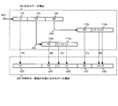
- FIG. 1A shows a configuration example of a network 1 including nodes 10 (N1 to N6) modeling a road network and links 12 (L1 to L8) connecting the nodes.
- the node code 10 is attached only to the node N1, and the others are omitted.
- the link code 12 is also attached only to the link L5, and the others are omitted.
- the link L1 connects the node N1 and the node N2
- the link L2 connects the node N2 and the node N3
- the link L3 connects the node N2 and the node N4.
- the link L4 connects the node N3 and the node N4, and the link L5 connects the node N3 and the node N5.
- the link L6 connects the node N4 and the node N5, the link L7 connects the node N4 and the node N6, and the link L8 connects the node N5 and the node N6.
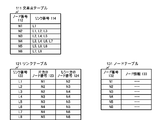
- FIG. 1B shows an example of a conventional data structure representing the network 1 shown in FIG. 1A, and includes an intersection table 111, a link table 121, and a node table 131.
- the intersection table 111 associates a node that is an intersection with a link that is a road connected to the node, and stores a link number 114 of a link connected to the node corresponding to the node number 112 of the node.
- the link number L1 is described for the node number N1
- the link numbers L1, L2, and L3 are described for the node number N2.
- L2, L4, and L5 are stored for N3, L3, L4, L6, and L7 are stored for N4, L5, L6, and L7 are stored for N5, and L7 and L8 are stored for N6.
- the portion existing on the memory is the portion from the N1 row to the N6 row. The same applies to the other tables described below.
- the link table 121 associates the link with the nodes at both ends thereof, and the node number 123 of one node connected to the link of the link number 122 and the node number of the other node with respect to the link number 122 124 is stored.
- the node number N1 and the node number N2 are stored as the link number L1
- the node number N2 and the node number N3 are stored as one node number 123 and the other node number 124 as the link number L2. Yes.
- N2 and N4 for L3, N3 and N4 for L4, N3 and N5 for L5, N4 and N5 for L6, N4 and N6 for L7, L8 N5 and N6 are stored.
- the node table 131 includes items of a node number 132 and node information 133, and stores node information such as the position of each node for each node number N1 to N6. Note that specific examples of node information are omitted.
- both nodes and links are network components, and a plurality of tables are provided.
- a route search it is necessary to refer to these multiple tables sequentially.
- the processing cost when performing the search is high. Therefore, the problem to be solved by the present invention is to provide a data structure for network expression with a small processing load during route search and a route search method using the data structure.
- the node number of one node of the link (hereinafter also referred to as the A-end node) and the other link connected to that node
- the link connection destination table storing the connection destination link number of the other node is provided as a data structure representing the network.
- the link connection destination table further includes a cost from the A-end node to the B-end node and a cost from the B-end node to the A-end node of each link, that is, a link cost. Furthermore, according to a preferred embodiment of the present invention, the link connection destination table stores the cost of connecting from each link to the link having the link number stored in the connection destination link number of the A-end and B-end nodes. be able to. A route from the start point to the end point is searched by following the link stored in the link connection destination table and the connection destination link, and an optimum route search is performed by calculating the cost of each route.
- the route search starts from the link related to the node on the start point side, and the connection destination of the node on the B end of the link connection destination table stored in the row of the link number Branch to the link of the link number, and further branch to the link of the link destination link number of the node at the B end stored in the link number row of those branched links in the link connection destination table. This is done by repeating the calculation while calculating the cost up to the link as the end node. Then, an optimum route among the routes from the start point to the end point is output as a search result.
- the branch of the route in the route search can be performed by referring only to the link number, thereby reducing the processing cost. Can do.
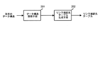
- FIG. 2A is a diagram illustrating an example of functional blocks for creating a data structure for network representation according to an embodiment of the present invention.
- Data having the conventional data structure shown in FIG. 1 is read by the data structure reading unit 201, and the link connection destination table generation unit 202 generates a link connection destination table based on the data.
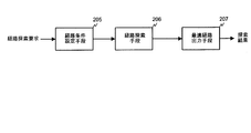
- FIG. 2B is a diagram illustrating an example of functional blocks for network route search according to an embodiment of the present invention.
- the route condition setting means 205 sets the route conditions such as the link connection destination table, the start point node, and the end point node corresponding to the network for which the route search is requested.
- the route search unit 206 searches for a route based on the conditions set by the route condition setting unit and calculates the cost of those routes.
- the optimum route output unit 207 outputs the route with the optimum cost among the routes searched by the route search unit 206 as a search result.
- FIG. 3 is a diagram illustrating a hardware configuration example according to an embodiment of the present invention.
- the route search processing and network representation data structure generation processing by the network route search device of the present invention are performed by the data processing device 301 including at least the central processing unit 302 and the cache memory 303 using the data storage device 308.
- the data storage device 308 having the link connection table 309 can be realized by the main storage device 305 or the external storage device 306, or it is possible to use a remote device connected via the communication device 307. is there.
- Each functional block such as the data structure reading unit 201 described with reference to FIGS. 2A and 2B can be realized by hardware illustrated in FIG. 3 and software having steps described later.
- the main storage device 305, the external storage device 306, and the communication device 307 are connected to the data processing device 301 by a single bus 304, but the connection method is not limited to this.
- the main storage device 305 can be in the data processing device 301.
- a temporary storage area corresponding to each process is used in order to use various values obtained during the process in a later process.
- the value stored or set in the temporary storage area may be called by the name of the temporary storage area.
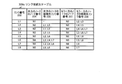
- FIG. 4A is a diagram illustrating an example of a data structure representing a network according to an embodiment of the present invention. Cost is omitted.
- the link connection destination table 309a includes a link number 232, a node number 234 of one node, a connection destination link number 235 of one node, a node number 237 of the other node, and a connection of the other node. It has an item of destination link number 238.
- each item corresponds to the network configuration example shown in FIG. 1A.
- N1 is stored in node number 234 of one node
- N2 is stored in node number 237 of the other node
- L2 and L3 are stored in connection destination link number 238 of the other node.
- Nothing is stored in the connection destination link number 235 of the node.
- the node number 234 of one node is N2
- the link destination link number 235 of one node is L1 and L3
- the node number 237 of the other node is N3
- the other node L4 and L5 are stored in the connection destination link number 238.
- N2, N3, N3, N4, N4, and N5 are assigned to the node number 234 of one node.
- N5, N6, and N6, L4 and L6 and L7, L3 and L6 and L7, L6 and L8, L5 and L8, L8, and L7 are stored in the connection destination link number 238 of the other node.
- FIG. 4B is a diagram for explaining the concept of generating network expression data according to an embodiment of the present invention from conventional network expression data.
- the conventional data structure 100 shown in the figure shows a part of the related rows of the link table 121 and the intersection table 111 shown in FIG. 1B.
- the line whose link number 122 indicated by the arrow 403 is L2 is extracted from the link table 121.
- the data structure 200 is a row in which the link number 232 of the link connection table 309a shown in FIG. 4A is L2. As indicated by the dotted arrow (A) from the link number 122 of the conventional data structure 100, the same link number as the link number 122 of the conventional data structure 100 is the link of the data structure 200 in one embodiment of the present invention.
- the number 232 is set.
- N2 row of node number 123 on one side of conventional data structure 100 is read from intersection table 111, and as indicated by dotted arrow (B), N2 of node number 112a, As indicated by the arrow (D), L1 and L3 which are not the same as the link number 122 among the link numbers 114a are respectively the node number 234 and the connection destination link of one node of the data structure 200 according to the embodiment of the present invention.
- the number 235 is set.
- the N3 row of the other node number 124 of the conventional data structure 100 is read from the intersection table 111 as indicated by the arrow 405, and the node number 112b is indicated as indicated by the dotted arrow (C).
- N3, as indicated by the dotted arrow (E), among the link numbers 114b, L4 and L5 which are not the same as the link number 122 are respectively the other node number 237 and the other of the data structure 200 in the embodiment of the present invention.
- the connection destination link number 238 of this node is set.
- FIG. 5 is a diagram illustrating an example of a processing flow for creating a data structure for network representation according to an embodiment of the present invention. Hereinafter, description will be made with reference to the illustrations of FIGS. 1A, 1B, 4A, and 4B.
- the head position of the link connection destination table is set as the link connection destination table writing position.
- the link connection destination table writing position is one of the above-described “temporary storage areas corresponding to each processing in order to use various values obtained during the processing in the subsequent processing”, This is a temporary storage area (not shown) for setting the write position of the link connection destination table.
- a temporary storage area (not shown) may be called depending on the contents of data stored or set therein.
- step S502 the head position of the link table is set as the link table reading position.
- the head position of the line whose link number 122 of the link table 121 is L1 is set.
- the link number is extracted from the link table pointed to by the link table reading position, and set to the link number that is a temporary storage area (hereinafter referred to as A only in the description of FIG. 5).
- the link number 122 at the link table read position is L2, and A is set to L2.
- one node number is read from the link table pointed to by the link table reading position, and set to one node number which is a temporary storage area (hereinafter referred to as B only in the explanation of FIG. 5).
- the node number 123 on one side of the link table reading position is N2, and N2 is set in B.
- step S505 the other node number is read from the link table pointed to by the link table reading position, and set to the other node number that is a temporary storage area (hereinafter referred to as C only in the description of FIG. 5). To do.
- the other node number 124 at the link table read position is N3, and C is set to N3.
- step S506 the link number excluding A is read from the intersection table pointed to by B, and is set to the connection link number of one node that is a temporary storage area (hereinafter referred to as D only in the description of FIG. 5).
- D a temporary storage area
- the link numbers of the intersection table pointed to by N2 set to B are L1, L2, and L3, and L1 and L3 except L2 set to A are set to D. Is done.
- step S507 the link number excluding A is read from the intersection table pointed to by C, and the connection link number of the other node that is a temporary storage area (hereinafter referred to as E only in the description of FIG. 5).
- E the connection link number of the other node that is a temporary storage area
- step S508 in the link connection destination table pointed to by the link connection destination table writing position, A as the link number, B as one node number, C as the other node number, and the connection destination of one node Set D as the link number and E as the connection destination number of the other node.
- L2 set to A in the link number 232 of the link connection destination table writing position corresponding to the arrow 403 and N2 set to B in one node number 234 are connected to one node.
- L1 and L3 set to D in the destination link number 235, N3 set to C in the other node number 237, and L4 and L5 set to E in the connection link destination number 238 of the other node Each is set.
- step S509 it is determined whether the link table read position is the end position of the link table. If it is not the end position, the next writing position is set as the link connection destination table writing position in step S510, the next reading position is set as the link table reading position in step S511, and the flow returns to step S503 to return to step S503. The processing in step S509 is repeated.
- step S509 if it is determined in step S509 that the link table read position is the last position of the link table, the link connection destination table is completed, and the process ends.
- steps S502 to S511 can be executed by the data structure reading unit 201 shown in FIG. 2A
- steps S501 and S508 can be executed by the link connection destination table generating unit 202. It should be noted that the correspondence between the above processing flow and the execution means of each step is merely an example, and it is obvious that various changes can be made.
- the link connection destination table is generated by the above processing, the data used to generate the link connection destination table can be deleted.
- the link connection destination table is connected to the start point of the route search. It is preferable to leave an intersection table for the convenience of the process of searching for a new link.
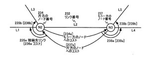
- FIG. 6A shows the cost of an embodiment of the present invention related to nodes N2 and N3 and links L1, L2, L3, L4, and L5 connected to them in the network configuration example shown in FIG. 1A. It is a concept.
- the link number 232 of the link connection destination table is L2
- the node number 234 of one node is N2
- the node of the other node B-end node
- the number 237 is N3.
- the cost [234a] to the other node from the node N2 to the node N3 and the cost [237a] to the other node from the node N3 to the node N2 are defined for the link L2. These costs are called section costs.
- connection costs to the links on the A end side and the B end side of the link are defined.
- the connection cost is defined.
- the connection cost [236a] from the link whose link number 232 is L2 to the link whose destination link number 235a of one node is L1 and the link where the link of one node is connected The connection cost [236b] to the connection destination link whose number 235b is L3 is defined.
- connection cost [239a] of the other node connection destination link number 238a to the connection link of L4 and the connection destination link number 238b of the other node to the connection destination link of L5 are connected.
- Connection cost [239b] is defined.
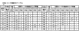
- FIG. 6B shows a link connection destination table 309b obtained by adding the above-described section cost and connection cost to the link connection destination table 309a illustrated in FIG. 4A.
- 1, 2, 3, 1, 2, 2, 3, 1 are set as examples of the cost 234a to the B end for the links with the link numbers 232 to L1 to L8, and the cost 237a to the A end is set as an example 2, 1, 2, 3, 1, 2, 2, 3 are set.
- connection cost 236a to the link 235a a connection cost 236b to the link 235b, and a connection cost 236c to the link 235c are set.
- connection cost 239a to the link 238a, the connection cost 239b to the link 238b, and the connection cost 239c to the link 238c are set as connection destination link information of the B-end node.
- connection destination link information of the node at the A end corresponding to the link number L1 of the link connection destination table 309b is not set.
- connection destination link information of the node at the B end of the link L1 1 is set for the connection cost to the link L2, and 1 is set for the connection cost to the link L3.
- connection cost to the link L1 is set to 2 as the connection destination link information of the node at the A end, and the connection cost to the link L3 is set to 1, and the connection destination link information of the node at the B end to the link L4
- the connection cost is set to 1
- the connection cost to the link L5 is set to 1.
- connection cost is set to 2
- connection cost to the link L6 is set to 2
- connection cost to the link L7 is set to 2.
- connection cost For the link L4, 1 is set as the connection cost to the link L2 and 1 is set as the connection cost to the link L5 as the connection destination link information of the node at the A end, and the link to the link L3 is set as the connection destination link information of the node at the B end.
- the connection cost is set to 2
- the connection cost to the link L6 is set to 3
- the connection cost to the link L7 is set to 3.
- connection cost is set to 1, and the connection cost to the link L8 is set to 2.
- connection cost to the link L6 is set for the connection cost to the link L3, 3 for the connection cost to the link L4, and 2 for the connection cost to the link L7 as the connection destination link information of the node at the A end.
- connection destination link information 2 is set for the connection cost to the link L5, and 3 is set for the connection cost to the link L8.
- connection destination link information of the node at the A end is set to 3 for the connection cost to the link L3, 4 to the connection cost to the link L4, and 1 to the connection cost to the link L6.
- connection destination link information 1 is set to the connection cost to the link L8.
- connection cost is set to 2.
- the actual physical network can be simulated more finely.
- relatively road-specific conditions such as road width and speed restrictions are reflected in the section cost, and traffic conditions between roads such as prohibition of right turn and presence of right turn signals are used as connection costs. It can be reflected.
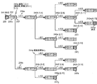
- FIG. 7A shows all routes developed in the route search starting from the node N1 of the network 1 illustrated in FIG. 1A and ending at the node N6.
- FIG. 7B shows the route search described above. It is the path
- a path expansion tree including a node (sometimes referred to as a path expansion node) having 237 and a branch (sometimes referred to as a path expansion branch) having a connection cost to a link included in a lower level path expansion node. . Therefore, the route search of the network corresponds to generating a route expansion tree and searching for the optimum route from the generated route.
- the node N1 is designated as the start point 241, and L1 is selected from the link connection destination table 309b as the link number 232 having the node number N1 as the node number 234 of one of the nodes (A-end node). 1 is extracted from the link connection destination table 309b pointed to by the link number L1 as the cost 234a to the B end, and N2 is read as the node number 237 of the B end node to generate the root node of the path expansion tree. . “0, 1” is calculated and attached to the node N2 at the B end as the route cost 242a [number of connections, accumulated cost] to N2.
- connection cost 239a to the link L2 is read as the connection cost 239a to the link L2 from the head of the connection destination link information of the B-end node from the link connection destination table 309b pointed to by the link number L1, and the connection cost is indicated by the solid line arrow.
- a route expansion branch accompanied by L2 [1] is generated.
- N2 as the node number 234 at the A end and 2 as the cost 234a to the B end are read from the link connection destination table 309b indicated by the link number L2, and N3 is read as the node number 237 of the node at the B end.
- [1, 4] is calculated as the route cost 242b to N3, and a route expansion node corresponding to the link L2 is generated.
- the accumulated cost 4 is obtained by adding the connection cost 1 from the link L1 to the link L2 and the section cost 2 of the link 2 to the accumulated cost 1 up to the node N2.
- connection cost 239b to the link L3 is read from the link connection destination table 309b indicated by the link number L1 as the next connection destination link information of the B-end node, and the link connection indicated by the link number L3.
- 3 is extracted as the cost 234a to the B end from the destination table 309b
- N4 is read as the node number 237 of the node at the B end
- [1, 5] is calculated as the path cost 242c to N4.
- 1 is read as the connection cost 239a to the link L4 from the link connection destination table 309b indicated by the link number L2, as the connection destination link information of the node at the B end, and further, the link number L4 indicates 1 is extracted as the cost 234a to the B end from the link connection destination table 309b, N4 is read as the node number 237 of the node at the B end, and [2, 6] is calculated as the path cost 242d to N4. .
- connection cost 239b to the link L5 is read from the link connection destination table 309b pointed to by the link number L2 as the connection destination link information of the node at the B end.
- 2 is extracted as the cost 234a to the B end from the link connection destination table 309b pointed to by N5
- N5 is read as the node number 237 of the node at the B end
- [2,7] is calculated as the route cost 242e to N5 Is done.
- connection cost 239a to the link L4 is read from the link connection destination table 309b pointed to by the link number L3 as the connection destination link information of the node at the B end. 1 is extracted as the cost 234a to the B end from the link connection destination table 309b to be pointed, and N4 is read as the node number 237 of the node at the B end.
- the node number set in the node number 237 at the B end of the link connection destination table 309b pointed to by the link number L4 is N4. Since the route returns to the node N4 at the B end of the connection source link L3, it is obvious that the route is unnecessary for the minimum cost calculation. Note that either the node at the A end or the node at the B end of the link at the connection destination matches the node at the B end of the link, and the node at the A end and the node at the B end of the same link match. Therefore, it is possible to determine whether or not to cancel the path expansion based on whether the A-end node of the connection destination link matches the B-end node of the connection source link.
- connection cost 239b to the link L6 is read from the link connection destination table 309b pointed to by the link number L3 as the connection destination link information of the node at the B end.
- 2 is extracted as the cost 234a to the B end from the link connection destination table 309b to point
- N5 is read as the node number 237 of the node at the B end
- [2, 9] is calculated as the route cost 242f to N5.
- connection cost 239c to the link L7 is read from the link connection destination table 309b pointed to by the link number L3 as the connection destination link information of the node at the B end. 3 is taken out from the link connection destination table 309b pointed to by B as the cost 234a to the B end, N6 is read out as the node number 237 of the node at the B end, and [2, 10] is calculated as the route cost 242g to N6 Is done. As shown in the figure, the node N6 is an end point 247g along the paths of links L1, L3, and L7.
- connection cost 239a to the link L3 is read from the link connection table 309b pointed to by the link number L4 as the connection link information of the B-end node.
- 3 is extracted as the cost 234a to the B end from the link connection destination table 309b pointed to by L3, and N4 is read as the node number 237 of the node at the B end. Accordingly, since the process returns to the node N4 at the B end of the link L4, the path cost is not calculated and the path expansion is also aborted.
- connection cost 239b to the link L6 is read from the link connection destination table 309b indicated by the link number L4 as the connection destination link information of the node at the B end. 2 is extracted as the cost 234a to the B end from the link connection destination table 309b pointed to by N5, N5 is read as the node number 237 of the node at the B end, and [3, 11] is calculated as the route cost 242h to N5 Is done.
- connection cost 239c to the link L7 is read from the link connection destination table 309b pointed to by the link number L4 as the connection destination link information of the B-end node. 3 is extracted as the cost 234a to the B end from the link connection destination table 309b pointed to by L7, N6 is read as the node number 237 of the node at the B end, and [3, 12] is set as the route cost 242i to N6. Calculated. As shown in the figure, the node N6 is an end point 247i along the route of links L1, L2, L4, and L7.
- connection cost 239b to the link L8 is read from the link connection destination table 309b pointed to by the link number L5 as the connection destination link information of the node at the B end. 1 is extracted as the cost 234a to the B end from the link connection destination table 309b pointed to by N6, N6 is read as the node number 237 of the node at the B end, and [3, 10] is calculated as the route cost 242j to N6 Is done. As shown in the figure, the node N6 is an end point 247j along the route of links L1, L2, L5, and L8.
- connection cost 239a to the link L5 is read as the connection destination link information of the B-end node from the link connection destination table 309b pointed to by the link number L6. 2 is extracted as the cost 234a to the B end from the link connection destination table 309b pointed to by L5, and N5 is read as the node number 237 of the node at the B end. Therefore, since the process returns to the node N5 at the B end of the link L6, the path cost is not calculated and the path expansion is also aborted.
- connection cost 239b to the link L8 is read from the link connection destination table 309b pointed to by the link number L8 as the connection destination link information of the node at the B end. 1 is extracted as the cost 234a to the B end from the link connection destination table 309b pointed to by N6, N6 is read as the node number 237 of the node at the B end, and [3, 13] is calculated as the route cost 242k to N6 Is done. As shown in the figure, the node N6 is an end point 247k along the route of links L1, L3, L6, and L8.
- connection cost 239a to the link L5 is read from the link connection destination table 309b pointed to by the link number L6 as the connection destination link information of the node at the B end.
- 2 is extracted as the cost 234a to the B end from the link connection destination table 309b indicated by the link number L5
- N5 is read as the node number 237 of the node at the B end. Therefore, since the process returns to the node N5 at the B end of the link L6, the path cost is not calculated and the path expansion is also aborted.
- connection cost 239b to the link L8 is read from the link connection destination table 309b pointed to by the link number L6 as the connection destination link information of the node at the B end. 1 is extracted as the cost 234a to the B end from the link connection destination table 309b indicated by the number L8, N6 is read as the node number 237 of the node at the B end, and the path cost 242m to N6 is [4, 15]. Is calculated. As shown in the figure, the node N6 is an end point 247m along the route of links L1, L2, L4, L6, and L8.
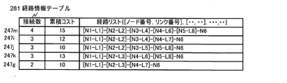
- the route information table 281 shown in FIG. 7B stores all the routes from the node N1 to the node N6 and stores the number of connections, the accumulated cost, and the route list.
- the route information table corresponds to the end points 247m, 247i, 247j, 247k, 247g shown in FIG. 7A, the number of connections is 4, 3, 3, 3, 2 and the accumulated costs are 15, 12, 10, 13, 10 Stored. Further, in the route list in which the node number and the link number of the node at the A end are combined, those corresponding to the route developed in FIG. 7A are stored. In the above description of the path expansion, the path expansion tree has been described from the upper layer.
- the path expansion tree is the position of the connection destination link information (path expansion tree) of the B-end node stored in the link connection destination table 309b.
- the upper side (right side) can be generated with priority.
- the route information stored in the route information table shown in FIG. 7B is based on the route expansion tree generated in this order.
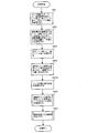
- FIG. 8A is a diagram for explaining an example of a schematic flow of a process for searching for an optimum route of a network according to an embodiment of the present invention.
- description will be made with reference to specific examples of the network configuration example shown in FIG. 1A, the link connection destination table 309b shown in FIG. 6B, the route information table 281 shown in FIG. At that time, “in the specific example,...
- a link connection destination table, a starting point node number and starting point link number for route search, and an end point node number are set.
- the link connection destination table for example, the head address and size are set by designating the name of the link connection destination table from outside the system.
- the link number of the link connected to the start point node may be set from the intersection table.
- N1 is set as the start point node number
- L1 is set as the start point link number
- N6 is set as the end point node number
- the link connection destination table 309b is set as the link connection destination table.
- step S802 the value “ ⁇ 1” is set as the number of connections in the path information, the value “0” is set as the accumulated cost, and the start node number is set as the next node number in step S803. Further, in step S804, the start link number is set as the connection destination link number, the value “0” is set in the connection cost, the link information reading position is initialized in step S804a, and the flow advances to step S805.
- N1 is set as the next node number and L1 is set as the connection destination link number.
- step S805 a route is searched based on the link connection destination table indicated by the connection destination link number, and the process proceeds to step S806. Details of the processing in step S805 will be described later with reference to FIG. 8B.
- step S806 the optimum route is output from the search result obtained in step S805, and the process ends. Details of the processing in step S806 will be described later with reference to FIG. 8C.
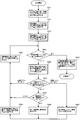
- FIG. 8B shows a detailed processing flow example of step S805 shown in FIG. 8A, and is a diagram for explaining the processing flow of network route search in one embodiment of the present invention.
- step S810 route information and link information are pushed onto the stack.
- the route information is the number of connections, the accumulated cost, the route list, and the writing position thereof
- the link information is the link connection destination indicated by the next node number, the connection destination link number, the connection cost, and the connection destination link number. This is the reading position of the contents of the table and the link information of the link connection destination table.
- the contents set in steps S801 to S804a shown in FIG. 8A are pushed onto the stack.
- step S811 the contents of the link connection destination table indicated by the connection destination link number are read out.
- the link number 232 that is the first row of the link connection destination table 309b is L1. The contents of the line are read.
- step S812 it is determined whether the next node number matches the node number at the A end of the link connection destination table read in step S811. If they match, the process proceeds to step S813, and if they do not match, the process branches to step S821.
- the node number 234 at the A end is N1
- the next node number is set as the start node number N1 in step S803 shown in FIG. 8A.
- the process proceeds to step S813. It is determined that they do not coincide with each other in a case where there is no route development indicated by a dotted arrow in the route development shown in FIG. 7A.
- step S813 1 is added to the number of connections in the path information, the connection cost and the cost to the B end of the link connection destination table read in step S811 are added to the accumulated cost, and the path information is written in the path list in the next position. The node number and the connection destination link number are written, and the writing position is updated.
- the connection cost is initially set in step S804 shown in FIG. 8A or set in step S818 described later.
- the route information is a primary storage area having an item for one line in the route information table 281 shown in FIG. 7B. In the first process in the specific example, the values “ ⁇ 1” and “0” are respectively initialized in step S802 shown in FIG.
- the link connection destination table is initialized. Since 1 is stored in the cost 234a to the B end of the read position of the link information, the number of connections and the accumulated cost of the path information are 0 and 1, respectively. Further, the next node number N1 and the connection destination link number L1 that are initially set in steps S802 and S803 shown in FIG. 8A are written at the head position of the route list of the route information.
- step S814 it is determined whether the node number at the B end of the link connection destination table read out at step S811 matches the end node number, and if it is determined that the node number at the B end does not match the end node number.
- the process branches to step S815.
- step S815 it is determined whether connection destination link information of the B-end node exists. This determination is made because if there is a dead end link in the route, there is no connection destination link information of the node at the B end, and the route cannot be expanded as described above. This is for branching to S821.
- step S815 if it is determined in step S815 that connection destination link information exists, the process advances to step S816 to set the node number at the B end to the next node number.
- step S817 the link connection destination table is set at the link information reading position. The head position of the connection destination link information of the B-end node is set. The priority of route search is determined by setting the readout position of the link information, and the route is searched with priority on the right side of the tree as described in the route search tree of the specific example.
- step S818 the connection destination link number and the connection cost are extracted and set from the connection destination link information of the B-end node of the link connection destination table indicated in step S811 indicated by the link information reading position.
- L2 and 1 stored as the link 238a and the cost 239a are extracted from the connection destination link information of the B-end node, set to the connection destination link number and the connection destination cost, and the process goes to step S810. Return.
- the determination result in step S812 is that the next node number does not match the node number at the A end (hereinafter also referred to as pruning determination), or step S814.
- the end point node number matches the B end node number (hereinafter, sometimes referred to as end point determination), or the determination result in step S818 does not include connection destination link information (hereinafter, dead end). Repeat until it becomes.
- step S820 the end point node number is written in the writing position of the path list of the path information, and the path information is sequentially written in the path information table, and the process proceeds to step S821.
- sequentially writing the route information in the route information table means writing the route information up to the end point node in the route information table while changing the row sequentially for each end point.
- step S821 route information and link information are popped from the stack, and the process proceeds to step S822.
- step S822 route information and link information are pushed onto the stack in step S810. That is, every time a route expansion node of the route expansion tree is generated, route information and link information about the generated route expansion node are pushed onto the stack.
- step S811 and subsequent steps in the loop processing described above processing is performed for a route expansion node below the route expansion node that has pushed the route information and link information onto the stack, and pruning determination, end point determination, or dead end determination is also performed. Since the processing is performed for the lower-level route expansion node, the route information and link information popped in the processing of step S821 executed after branching from the loop processing are the routes for which the pruning determination, the end point determination, or the dead end determination is performed. This is for a route expansion node higher than the expansion node.
- step S822 it is determined whether the stack is empty. If the stack is empty, the path development is completed, and the process is terminated. If not, the process proceeds to step S823. In step S822, it is determined that the stack is empty when the path is expanded to the end point 247g in the example of FIG. 7A.
- step S823 it is determined whether all the connection destination link information of the B-end node of the link connection destination table popped in step S821 has been processed. If all the processing has been completed, the process returns to step S821 to further pop the route information and link information for the route development node that is one level higher from the stack. If not all processed, the process proceeds to step S824, the next read position is set as the link information read position, the process proceeds to step S818, and the above loop processing is merged.
- the start point node is the node number of the node at the A end of the link connection destination table.
- the start point node is the node number of the node at the B end.
- the A end should be read as the B end, and the B end should be read as the A end.
- the route information and the link information during the route development are held by the stack, if the route information and the link information during the route development are stored in a format that can be identified, The retention of route information and link information during route development is not limited to the stack.
- FIG. 8C is a diagram illustrating an example of a processing flow for determining an optimum route according to an embodiment of the present invention. Description will be made with reference to the route information table 281 illustrated in FIG. 7B as appropriate.
- a maximum value (all 1 in terms of bit value) is set as the minimum number of connections and the minimum accumulated cost.
- the head position of the path information table is set as a path information reading position.
- the head position of the route information table is set as the optimum route information reading position.
- the position of the route information corresponding to the end point 247m is initially set to the read position of the route information and the read position of the optimum route information.
- step S834 it is determined whether or not all the route information tables have been processed. If not processed, the number of connections and the accumulated cost are read from the route information table pointed to by the read position of the route information in step S835.
- step S836 the magnitude relationship between the read accumulated cost and the minimum accumulated cost is determined. If the accumulated cost is smaller than the minimum accumulated cost, the process branches to step S837, and the accumulated cost read in step S835 is set as the minimum accumulated cost. Set. In the first determination process of step S836, since the maximum value is set in step S831 for the minimum accumulated cost, the process branches to step S837, and the accumulated cost at the head position of the path information table is set in the minimum accumulated cost. Proceed to step S840.
- step S836 determines whether the accumulated cost is equal to the minimum accumulated cost. If the determination result in step S838 is “Yes”, the number of connections is set as the minimum number of connections in step S839, and the process proceeds to step S840.
- step S840 the route information reading position is set as the optimum route information reading position, and the flow advances to step S841. If the determination result in step S838 is “No”, the process proceeds to step S841. If it is determined in step S836 that the accumulated cost is greater than the minimum accumulated cost, the process proceeds to step S841. In step S841, the path information read position is set to the next read position, and the process returns to step S834.
- step S842 If it is determined in step S834 that all the route information tables have been processed, in step S842, the route information table pointed to by the reading position of the optimum route information is read out and output as optimum route information, and the process is terminated.
- the network route searching apparatus of the present invention can be constructed on a computer by a storage means for storing a link connection destination table and a program for causing the computer to execute the processes shown in FIGS. 8A to 8C.
- the data structure creation method of the present invention can be realized by the program for causing the computer to execute the process for creating the data structure for the route search shown in FIG. 5 and its equivalent.
- the means etc. which produce the data structure of this invention are implement
- a data structure for route search of the present invention and a computer-readable recording medium on which data having the data structure is recorded are also included in the embodiment of the present invention.
- the link connection destination table which is a new data structure provided by the present invention described in detail above, it is possible to efficiently search for a network route.
- the present invention is not limited to this, it is very effective when applied to the optimum route search of a device equipped with a small computer such as a car navigation device.
Landscapes
- Engineering & Computer Science (AREA)
- Radar, Positioning & Navigation (AREA)
- Remote Sensing (AREA)
- Automation & Control Theory (AREA)
- Physics & Mathematics (AREA)
- General Physics & Mathematics (AREA)
- Navigation (AREA)
- Traffic Control Systems (AREA)
- Data Exchanges In Wide-Area Networks (AREA)
Priority Applications (1)
| Application Number | Priority Date | Filing Date | Title |
|---|---|---|---|
| US13/064,304 US20110170536A1 (en) | 2008-09-17 | 2011-03-17 | Network path finding apparatus, method, and program |
Applications Claiming Priority (2)
| Application Number | Priority Date | Filing Date | Title |
|---|---|---|---|
| JP2008-238539 | 2008-09-17 | ||
| JP2008238539A JP2010071767A (ja) | 2008-09-17 | 2008-09-17 | ネットワーク経路探索装置、方法及びプログラム |
Related Child Applications (1)
| Application Number | Title | Priority Date | Filing Date |
|---|---|---|---|
| US13/064,304 Continuation US20110170536A1 (en) | 2008-09-17 | 2011-03-17 | Network path finding apparatus, method, and program |
Publications (1)
| Publication Number | Publication Date |
|---|---|
| WO2010032372A1 true WO2010032372A1 (ja) | 2010-03-25 |
Family
ID=42039224
Family Applications (1)
| Application Number | Title | Priority Date | Filing Date |
|---|---|---|---|
| PCT/JP2009/003901 Ceased WO2010032372A1 (ja) | 2008-09-17 | 2009-08-14 | ネットワーク経路探索装置、方法及びプログラム |
Country Status (3)
| Country | Link |
|---|---|
| US (1) | US20110170536A1 (enExample) |
| JP (1) | JP2010071767A (enExample) |
| WO (1) | WO2010032372A1 (enExample) |
Families Citing this family (3)
| Publication number | Priority date | Publication date | Assignee | Title |
|---|---|---|---|---|
| JP5440477B2 (ja) | 2010-01-29 | 2014-03-12 | 株式会社デンソー | 電子機器 |
| US10042362B2 (en) | 2016-11-18 | 2018-08-07 | Waymo Llc | Dynamic routing for autonomous vehicles |
| US11218404B2 (en) | 2018-05-15 | 2022-01-04 | At&T Intellectual Property I, L.P. | Network diversity resolution system |
Citations (5)
| Publication number | Priority date | Publication date | Assignee | Title |
|---|---|---|---|---|
| JPH07113653A (ja) * | 1993-10-19 | 1995-05-02 | Sumitomo Electric Ind Ltd | 経路計算装置 |
| JP2005069751A (ja) * | 2003-08-21 | 2005-03-17 | Hitachi Ltd | 通信型車両ナビゲーションシステムのサーバ装置、車載端末装置及びそのプログラム |
| JP2005077299A (ja) * | 2003-09-02 | 2005-03-24 | Casio Comput Co Ltd | ナビゲーションシステム、及び、プログラム |
| JP2007101865A (ja) * | 2005-10-04 | 2007-04-19 | Denso Corp | 路線地図データの生成方法、路線地図データ更新システム、及び、路線地図データ管理装置 |
| JP2007132747A (ja) * | 2005-11-09 | 2007-05-31 | Xanavi Informatics Corp | ナビゲーションシステム及び情報取得方法 |
Family Cites Families (4)
| Publication number | Priority date | Publication date | Assignee | Title |
|---|---|---|---|---|
| US6370119B1 (en) * | 1998-02-27 | 2002-04-09 | Cisco Technology, Inc. | Computing the widest shortest path in high-speed networks |
| US7596088B2 (en) * | 2006-01-24 | 2009-09-29 | Corrigent Systems Ltd. | Route selection with bandwidth sharing optimization over rings |
| EP1990786B1 (en) * | 2006-02-28 | 2021-05-19 | Toyota Jidosha Kabushiki Kaisha | Object path prediction method and apparatus |
| US8179872B2 (en) * | 2007-05-09 | 2012-05-15 | Research In Motion Limited | Wireless router system and method |
-
2008
- 2008-09-17 JP JP2008238539A patent/JP2010071767A/ja active Pending
-
2009
- 2009-08-14 WO PCT/JP2009/003901 patent/WO2010032372A1/ja not_active Ceased
-
2011
- 2011-03-17 US US13/064,304 patent/US20110170536A1/en not_active Abandoned
Patent Citations (5)
| Publication number | Priority date | Publication date | Assignee | Title |
|---|---|---|---|---|
| JPH07113653A (ja) * | 1993-10-19 | 1995-05-02 | Sumitomo Electric Ind Ltd | 経路計算装置 |
| JP2005069751A (ja) * | 2003-08-21 | 2005-03-17 | Hitachi Ltd | 通信型車両ナビゲーションシステムのサーバ装置、車載端末装置及びそのプログラム |
| JP2005077299A (ja) * | 2003-09-02 | 2005-03-24 | Casio Comput Co Ltd | ナビゲーションシステム、及び、プログラム |
| JP2007101865A (ja) * | 2005-10-04 | 2007-04-19 | Denso Corp | 路線地図データの生成方法、路線地図データ更新システム、及び、路線地図データ管理装置 |
| JP2007132747A (ja) * | 2005-11-09 | 2007-05-31 | Xanavi Informatics Corp | ナビゲーションシステム及び情報取得方法 |
Also Published As
| Publication number | Publication date |
|---|---|
| US20110170536A1 (en) | 2011-07-14 |
| JP2010071767A (ja) | 2010-04-02 |
Similar Documents
| Publication | Publication Date | Title |
|---|---|---|
| Ziliaskopoulos et al. | A note on least time path computation considering delays and prohibitions for intersection movements | |
| CN105468702B (zh) | 一种大规模rdf数据关联路径发现方法 | |
| US10062188B2 (en) | Customizable route planning using graphics processing unit | |
| US20200249033A1 (en) | Method for producing alternative route suggestions | |
| Fischer et al. | Dynamic graph generation for the shortest path problem in time expanded networks | |
| JP2011007713A (ja) | 多点対間最短経路探索方法およびシステム | |
| CN107121146B (zh) | 基于路链深度的最优路径规划方法 | |
| JP5845016B2 (ja) | 地図差分データ作成装置及び地図差分データ作成方法 | |
| JP2011013750A (ja) | システムの構成要素の設計アーキテクチャを自動設計する自動設計装置、自動設計方法及び自動設計プログラム | |
| JP2001165681A (ja) | 交通ネットワーク経路探索方法 | |
| WO2010032372A1 (ja) | ネットワーク経路探索装置、方法及びプログラム | |
| Scano et al. | Adaptations of k-shortest path algorithms for transportation networks | |
| JPH07175621A (ja) | 最適メニュー問い合わせ方式及び階層的メニュー問い合わせによる構造データの編集方式 | |
| CN102523155B (zh) | 一种基于Boost库的K则最短路径搜索方法和系统 | |
| JP2008157698A (ja) | 経路探索方法、プログラム及びシステム | |
| CN102158388A (zh) | 极值路由确定引擎和方法 | |
| JP5132694B2 (ja) | データ生成装置、データ生成方法及び経路探索装置 | |
| US11138351B2 (en) | Estimated distance calculator, estimated distance calculation method, estimated distance calculation program, and automated planner | |
| JP2010286978A (ja) | 経路探索方法、装置及びプログラム | |
| CN115344926B (zh) | 二维钢筋数据联动方法、装置、电子设备及存储介质 | |
| CN111461408B (zh) | 最短路径搜索方法、装置及存储介质 | |
| CN114138984A (zh) | 关系图谱更新方法、装置、计算设备及存储介质 | |
| KR20120067185A (ko) | 실시간 길찾기 장치 및 방법 | |
| JP2010071767A5 (enExample) | ||
| JPWO2014207827A1 (ja) | データ分析装置、rdfデータの拡張方法、およびデータ分析プログラム |
Legal Events
| Date | Code | Title | Description |
|---|---|---|---|
| 121 | Ep: the epo has been informed by wipo that ep was designated in this application |
Ref document number: 09814218 Country of ref document: EP Kind code of ref document: A1 |
|
| NENP | Non-entry into the national phase |
Ref country code: DE |
|
| 122 | Ep: pct application non-entry in european phase |
Ref document number: 09814218 Country of ref document: EP Kind code of ref document: A1 |