WO2010026719A1 - 洗濯機 - Google Patents
洗濯機 Download PDFInfo
- Publication number
- WO2010026719A1 WO2010026719A1 PCT/JP2009/004193 JP2009004193W WO2010026719A1 WO 2010026719 A1 WO2010026719 A1 WO 2010026719A1 JP 2009004193 W JP2009004193 W JP 2009004193W WO 2010026719 A1 WO2010026719 A1 WO 2010026719A1
- Authority
- WO
- WIPO (PCT)
- Prior art keywords
- drum
- vibration
- frequency component
- receiving cylinder
- laundry
- Prior art date
Links
Images

Classifications
-
- D—TEXTILES; PAPER
- D06—TREATMENT OF TEXTILES OR THE LIKE; LAUNDERING; FLEXIBLE MATERIALS NOT OTHERWISE PROVIDED FOR
- D06F—LAUNDERING, DRYING, IRONING, PRESSING OR FOLDING TEXTILE ARTICLES
- D06F34/00—Details of control systems for washing machines, washer-dryers or laundry dryers
- D06F34/14—Arrangements for detecting or measuring specific parameters
- D06F34/16—Imbalance
-
- D—TEXTILES; PAPER
- D06—TREATMENT OF TEXTILES OR THE LIKE; LAUNDERING; FLEXIBLE MATERIALS NOT OTHERWISE PROVIDED FOR
- D06F—LAUNDERING, DRYING, IRONING, PRESSING OR FOLDING TEXTILE ARTICLES
- D06F25/00—Washing machines with receptacles, e.g. perforated, having a rotary movement, e.g. oscillatory movement, the receptacle serving both for washing and for centrifugally separating water from the laundry and having further drying means, e.g. using hot air
-
- D—TEXTILES; PAPER
- D06—TREATMENT OF TEXTILES OR THE LIKE; LAUNDERING; FLEXIBLE MATERIALS NOT OTHERWISE PROVIDED FOR
- D06F—LAUNDERING, DRYING, IRONING, PRESSING OR FOLDING TEXTILE ARTICLES
- D06F33/00—Control of operations performed in washing machines or washer-dryers
- D06F33/30—Control of washing machines characterised by the purpose or target of the control
- D06F33/48—Preventing or reducing imbalance or noise
-
- D—TEXTILES; PAPER
- D06—TREATMENT OF TEXTILES OR THE LIKE; LAUNDERING; FLEXIBLE MATERIALS NOT OTHERWISE PROVIDED FOR
- D06F—LAUNDERING, DRYING, IRONING, PRESSING OR FOLDING TEXTILE ARTICLES
- D06F49/00—Domestic spin-dryers or similar spin-dryers not suitable for industrial use
- D06F49/04—Bowl drive
-
- D—TEXTILES; PAPER
- D06—TREATMENT OF TEXTILES OR THE LIKE; LAUNDERING; FLEXIBLE MATERIALS NOT OTHERWISE PROVIDED FOR
- D06F—LAUNDERING, DRYING, IRONING, PRESSING OR FOLDING TEXTILE ARTICLES
- D06F2103/00—Parameters monitored or detected for the control of domestic laundry washing machines, washer-dryers or laundry dryers
- D06F2103/26—Unbalance; Noise level
Definitions
- the present invention relates to a drum-type washing machine that includes a rotatable drum in a receiving tube that is elastically supported, and performs washing, rinsing, and dehydration or drying of the laundry in the drum.
- the drum behavior during washing operation such as unbalance detection control during dehydration and laundry movement amount detection control during washing, and the laundry behavior in the drum are measured. ⁇ Estimated.
- the laundry situation is appropriately improved by controlling the imbalance during dehydration and controlling the amount of movement of the laundry during washing. .
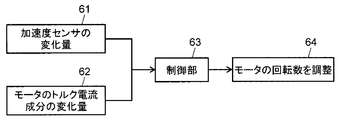
- a semiconductor acceleration sensor is attached to a drum receiving cylinder, and, as shown in FIG. 6, a laundry garment (laundry) is obtained from a change amount 61 of an acceleration sensor output and a change amount 62 of a torque current component of a motor.
- the behavior of the object The controller 63 changes the number of rotations of the motor that rotates the drum according to the estimated behavior of the laundry.
- the present invention provides a washing machine with excellent washing performance by accurately grasping the washing situation and rotating the drum at a rotation speed optimum for washing.
- the present invention includes a drum that accommodates and rotates laundry, a receiving cylinder that accommodates the drum, an elastic suspension that suspends the receiving cylinder from above the housing, and a vibration damper that supports the receiving tube from below the housing, And a motor for rotating the drum. Further, the present invention provides a vibration detection unit that detects vibration of the receiving cylinder, a frequency component calculation unit that calculates a frequency component for the vibration detected by the vibration detection unit, and a frequency component calculated by the frequency component calculation unit. And a rotation speed control unit that changes the rotation speed of the motor according to the size.
- the elastic suspension part suspends the receiving tube from a position symmetrical with respect to the rotation axis of the drum, and the vibration detection unit detects vibration in the front-rear direction of the receiving tube. Further, the rotation speed control unit changes the rotation speed of the motor according to the magnitude of the frequency component calculated for the vibration in the front-rear direction.
- the present invention also provides a drum that accommodates and rotates laundry, a receiving cylinder that accommodates the drum, an elastic suspension that suspends the receiving cylinder from above the housing, and a vibration damping damper that supports the receiving tube from below the housing. And a motor for rotating the drum. Further, the present invention provides a vibration detection unit that detects vibration of the receiving cylinder, a frequency component calculation unit that calculates a frequency component for the vibration detected by the vibration detection unit, and a frequency component calculated by the frequency component calculation unit. And a rotation speed control unit that changes the rotation speed of the motor according to the size. Further, the elastic suspension unit suspends the receiving tube from a position on the rotation axis of the drum, and the vibration detection unit detects vibration in the left-right direction of the receiving tube. Further, the rotation speed control unit changes the rotation speed of the motor according to the magnitude of the frequency component calculated for the vibration in the left-right direction.
- the direction of the vibration component derived from the vibration of the receiving tube due to the movement of the laundry is determined by the difference in the support position of the receiving tube with respect to the housing. That is, the direction of the vibration component used for calculation value calculation in the frequency component calculation unit is determined. Accordingly, it is possible to accurately grasp the movement of the laundry in the drum, perform drum rotation control suitable for washing clothes, and improve the cleaning performance.
- FIG. 1 is a schematic side view of a washing machine according to Embodiment 1 of the present invention.
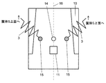
- FIG. 2 is a schematic top view showing the washing machine support structure according to Embodiment 1 of the present invention.
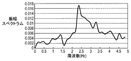
- FIG. 3A is a graph showing the longitudinal component analysis results obtained from the vibration of the receiving cylinder of the washing machine in the first embodiment of the present invention.
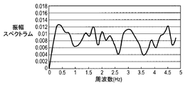
- FIG. 3B is a graph showing a left-right direction component analysis result obtained from vibration of a receiving cylinder of the washing machine in the first embodiment of the present invention.
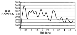
- FIG. 3C is a graph showing the vertical component analysis result obtained from the vibration of the receiving cylinder of the washing machine in the first embodiment of the present invention.
- FIG. 3A is a graph showing the longitudinal component analysis results obtained from the vibration of the receiving cylinder of the washing machine in the first embodiment of the present invention.
- FIG. 3B is a graph showing a left-right direction component analysis result obtained from vibration of a receiving cylinder of the washing machine in the first embodiment of the present invention.
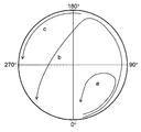
- FIG. 4 is an explanatory diagram of a washing state inside the drum of the washing machine according to the first embodiment of the present invention.
- FIG. 5 is a schematic top view showing the washing machine support structure according to Embodiment 2 of the present invention.
- FIG. 6 is a diagram for explaining the control of the motor rotation speed in a conventional washing machine.
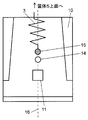
- FIG. 1 is a schematic side view of the washing machine according to the first embodiment.
- a receiving cylinder 2 containing a rotatable drum 1 is supported by a housing 5 by an elastic hanging portion 3 and a vibration damping damper 4.
- a motor 6 is fixed to the bottom of the receiving tube 2, and the drum 1 is rotated at a predetermined rotational speed via a belt 7.
- the laundry garment 9 as the laundry put into the drum 1 through the garment loading / unloading port 8 provided in the front of the washing machine is scooped up by the baffle 10 provided in the drum 1 as the drum 1 rotates. And falls from the top to the bottom.
- the cleaning effect is enhanced by the kinetic energy when struck against the bottom.
- the vibration of the receiving tube 2 generated by the movement of the laundry 9 is detected by the vibration detection unit 11 and the detection result is transmitted to the frequency component calculation unit 12. Further, the value calculated by the frequency component calculation unit 12 is transmitted to the rotation speed control unit 13, and the motor 6 is corrected and controlled by the rotation speed control unit 13 to a rotation speed at which appropriate tapping is realized.
- the support position of the vibration isolating damper 4 is attached on the substantially vertical line or on the vertical line from the center of gravity when the drum 1 and the receiving cylinder 2 are combined.
- This is detected by the vibration detection unit 11 by stabilizing the bottom of the receiving tube 2 because the vibration at the bottom is large and the shock is continuously received when the laundry 9 falls from the top of the drum 1. This is so as not to include shaking other than the movement of the laundry 9 in the signal to be performed.
- the vibration detection unit 11 of the present embodiment includes an acceleration sensor, and the acceleration sensor may be any of a semiconductor acceleration sensor, a piezoelectric acceleration sensor, and the like.
- FIG. 2 shows an example of a schematic top view showing the support structure in the present embodiment.
- the center of gravity point 14 indicates the center of gravity in a state where the drum 1 and the receiving tube 2 are combined.
- the receiving tube 2 is supported by the elastic suspension 3 at two support points 15.
- the center axis 16 indicates the rotation axis of the drum 1.
- the elastic suspension part 3 suspends the receiving tube 2 from a position symmetrical with respect to the central axis 16 line of the drum 1. More specifically, the elastic suspension portion 3 is a position on a plane including the center of gravity 14 in a state where the drum 1 and the receiving cylinder 2 are combined, and includes the center axis 16 of the drum 1 and extends in the vertical direction. The receiving tube 2 is suspended from a position symmetrical with respect to the plane.
- the frequency component calculation unit 12 performs discrete Fourier transform (DFT) or fast Fourier transform (FFT) from the received acceleration value to calculate the magnitude of the frequency component (Fourier amplitude spectrum, power spectrum).
- the rotation speed control unit 13 can increase or decrease the number of rotations of the drum according to the size of the specific frequency component calculated by the frequency component calculation unit 12 or the sum of the frequency components, thereby improving the washing performance of the laundry. Become.
- the movement of the laundry garment 9 is received with a specific cycle that occurs when the laundry 9 is placed in a tapping state that is effective for removing dirt during washing.
- the vibration from the cylinder 2 is alleviated by the elastic suspension portion 3 in the left-right direction, and is alleviated by the vibration-proof damper 4 in the up-down direction. Therefore, it becomes impossible to grasp the exact frequency component. Accordingly, in this case, the vibration in the front-rear direction reflects the movement of the laundry garment 9 moving inside the drum 1 with the least relaxation.
- an acceleration sensor of the vibration detection unit 11 that can detect only in the front-rear direction, but vibration in three axes (front-rear, left-right, up-down) can be detected, and the front and rear A configuration may be adopted in which only vibration in the direction is employed.
- the elastic suspension portion 3 that connects the receiving tube 2 and the upper portion of the housing 5 is in a symmetrical position with the center of gravity 14 on the central axis 16 as the center.
- the analysis result when the vibration from the receiving cylinder 2 is decomposed into each direction component in the supported state is shown.
- FIG. 3A to FIG. 3C cleaning evaluation was performed with the drum 1 rotating at 45 rpm and the weight of the laundry garment 9 being 2.0 kg.
- 3A is a graph showing the analysis result of the longitudinal component obtained from the vibration of the receiving cylinder 2
- FIG. 3B is a graph showing the analysis result of the horizontal component
- FIG. 3C is the analysis result of the analytic component in the vertical direction. It is a graph which shows.
- the circle in FIG. 4 represents the opening of the drum 1, and the bottom surface is represented as 0 ° and the upper portion is represented as 180 °. Since rotation of the drum is reversed at 90 ° and 270 °, there is no problem even if reversed left and right. Now, in order to improve the cleaning performance, it is most suitable to tap the washing garment 9 with the baffle 10 (see FIG. 1) and drop it from the top (trajectory b). When the laundry clothes 9 sticks to the drum 1 and moves (trajectory c), or when the laundry clothes 9 rotate around the bottom of the drum 1 (trajectory a), it is unsuitable for improving the cleaning performance. is there.
- the condition that the garment can be washed is a frequency of 1. 5 Hz to 3.0 Hz. If the frequency is less than 1.5 Hz, the laundry garment 9 rotates at the bottom and the laundry garment 9 is attached to the drum 1 at a frequency higher than 3.0 Hz.
- the sum of the peak values for each specific frequency interval (for example, 0.15 Hz) in each frequency region is the peak value for each specific frequency interval (for example, 0.15 Hz) in all frequency regions.
- the vibration direction was the front-rear direction
- the state of washing was 48%
- the grooving state was 16%
- the sticking state was 36%
- the vibration direction was the left-right direction
- the state of washing was 35%
- the grooving state was 33%
- the sticking state was 32%.
- the vibration direction was the vertical direction
- the washing state was 36%
- the grooving state was 39%
- the sticking state was 25%.
- the vibration component in the front-rear direction largely reflects the signal of the washing state and can be clearly distinguished from signals in other areas. Therefore, even when the value fluctuates with time, it can be determined that the vibration component in the front-rear direction corresponds to the movement of the clothes in the drum.
- the control is performed so that the amplitude spectrum of the frequency component resulting from the washing is increased as described above. If there are many components with a frequency longer than the frequency component region (for example, 1.5 Hz to 3.0 Hz when the drum rotational speed is 45 rpm) due to the washing with a beat, the drum It is considered that the laundry garment 9 is attached to the wall surface of the drum 1 and is rotating without falling at the upper part of the drum 1. Therefore, it is predicted that the frequency of vibration applied to the drum 1 is reduced. Therefore, control is performed such that the laundry 1 is dropped from the wall surface of the drum 1 by reducing the rotation speed of the drum 1.
- the present embodiment includes a drum 1 that accommodates and rotates laundry, a receiving cylinder 2 that accommodates the drum 1, and an elastic suspension portion 3 that suspends the receiving cylinder 2 from above the housing 5.
- the vibration isolating damper 4 that supports the receiving tube 2 from below the housing 5, the motor 6 that rotates the drum 1, the vibration detecting unit 11 that detects the vibration of the receiving tube 2, and the vibration detected by the vibration detecting unit 11
- a frequency component calculation unit 12 that calculates the frequency component
- a rotation speed control unit 13 that changes the rotation speed of the motor 6 according to the magnitude of the frequency component calculated by the frequency component calculation unit 12, and an elastic suspension unit 3 suspends the receiving tube 2 from a position symmetrical with respect to the rotation axis 16 of the drum 1,
- the vibration detecting unit 11 detects vibration in the front-rear direction of the receiving tube 2, and the rotational speed control unit 13 Calculated for vibration in direction Having the configuration of changing the rotational speed of the motor 6 according to the magnitude of the frequency component.
- the clothes rotate with the rotation of the drum 1, and when the clothes are lifted and dropped from above, they collide with the lower drum and generate vibration.
- the elastic suspension part 3 suspends the receiving tube 2 from a position symmetrical with respect to the rotation axis 16 line of the receiving tube 2. For this reason, the movement of the receiving tube in the left-right direction is alleviated by the elastic force of the elastic suspension part 3, resulting in vibration unrelated to the movement of the clothing. Similarly, the movement of the receiving cylinder 2 in the vertical direction is also mitigated by the elastic force and damping force of the vibration damping damper 4. However, the vibration in the front-rear direction of the receiving tube 2 can be sufficiently detected without being buffered by the elastic suspension part 3 or the vibration damping damper 4.
- FIG. 5 is a schematic top view showing a support structure according to Embodiment 2 of the present invention.
- the same reference numerals are used for the same components as in the first embodiment, and description thereof is omitted.
- the elastic suspension part 3 that connects the receiving tube 2 and the upper part of the housing 5 includes a center of gravity point 14 on a substantially central axis 16. Alternatively, it is supported at a support point 15 on the central axis 16. In this case, the suspension is balanced with the vibration damping damper 4 that supports the lower portion of the receiving tube 2. Therefore, periodic vibration is generated according to the movement of the laundry clothes 9 inside the drum 1.
- Other configurations of the washing machine are the same as those in the first embodiment.
- the vibration detection unit 11 detects at least one vibration component of the upper, lower, left, and right of the receiving cylinder 2, and the detected acceleration in the direction is sent to the frequency component calculation unit 12 as a signal value, and then the rotational speed control is performed. Used as output to the unit 13.
- the frequency component calculator 12 performs discrete Fourier transform (DFT) or fast Fourier transform (FFT) from the received acceleration value to calculate the magnitude of the frequency component (Fourier amplitude spectrum, power spectrum).
- DFT discrete Fourier transform
- FFT fast Fourier transform
- the rotational speed control unit 13 can improve the cleaning performance of the laundry garment 9 by increasing or decreasing the number of rotations of the drum according to the calculated magnitude of the specific frequency component and the sum of the frequency components.
- the elastic suspension part 3 suspends the receiving tube 2 from a position on the rotation axis 16 line of the drum 1 as shown in FIG. More specifically, the elastic suspension part 3 suspends the receiving tube 2 from the position of a plane including the rotation axis 16 line of the drum 1 and extending in the vertical direction.
- the number of supporting portions of the elastic suspension part 3 may be one as shown in FIG. 5 or may be two in the front-rear direction at the position of the plane. It is not limited.
- the movement of the laundry garment 9 has a specific cycle that occurs when placed in a tapping state that is effective in removing dirt.
- the vibration from the receiving cylinder 2 is relieved by the elastic suspension part 3 in the front-rear direction, and is relieved by the vibration-proof damper 4 in the up-down direction. Therefore, in this case, the vibration in the left-right direction reflects the movement of the laundry 9 that is moving inside the drum 1 without being relaxed. Therefore, in the present embodiment, it is sufficient to attach an acceleration sensor of the vibration detection unit 11 that can detect only in the left-right direction.
- vibrations in three axes front-rear, left-right, up-down
- a structure that employs only vibration in the direction may be employed.
- the vertical direction and the left and right are actually relative to the central axis 16 of the drum 1.
- vibration is relatively greater than in the front-rear direction. Therefore, detecting the vibration in the left-right direction is advantageous in this case in order to grasp the movement of the laundry 9 in the drum 1. Therefore, in the case where the support structure is as shown in FIG. 5, the cleaning performance is enhanced by controlling the rotational speed of the drum using the vibration component in the horizontal direction of the receiving tube 2 as in the first embodiment. It becomes possible.
- the rotation speed of the drum 1 is decreased to control the laundry 9 to drop from the drum 1 wall surface.
- the present embodiment includes a drum 1 that accommodates and rotates laundry, a receiving cylinder 2 that accommodates the drum 1, and an elastic suspension portion 3 that suspends the receiving cylinder 2 from above the housing 5.
- the vibration isolating damper 4 that supports the receiving tube 2 from below the housing 5, the motor 6 that rotates the drum 1, the vibration detecting unit 11 that detects the vibration of the receiving tube 2, and the vibration detected by the vibration detecting unit 11
- a frequency component calculation unit 12 that calculates the frequency component
- a rotation speed control unit 13 that changes the rotation speed of the motor 6 according to the magnitude of the frequency component calculated by the frequency component calculation unit 12, and an elastic suspension unit 3 suspends the receiving tube 2 from a position on the rotation axis 16 of the drum 1,
- the vibration detecting unit 11 detects left-right vibration of the receiving tube 2, and the rotational speed control unit 13 detects vibration in the left-right direction.
- the clothes rotate with the rotation of the drum 1, and when the clothes are lifted and dropped from above, they collide with the lower drum 1 to generate vibration.
- the elastic suspension part 3 suspends the receiving tube 2 from a position on the rotation axis 16 line of the receiving tube 2. For this reason, the movement of the receiving tube 2 in the front-rear direction is alleviated by the elastic force of the elastic suspension part 3, and the vibration is not related to the movement of the clothes. Similarly, the movement of the receiving cylinder 2 in the vertical direction is also mitigated by the elastic force and damping force of the vibration damping damper 4. However, the vibration in the left-right direction of the receiving cylinder 2 can be sufficiently detected without being buffered by the elastic suspension part 3 or the vibration damping damper 4.
- the direction of the vibration component derived from the vibration of the receiving tube due to the movement of the laundry is determined by the difference in the support position of the receiving tube with respect to the housing. That is, the direction of the vibration component used for calculation value calculation in the frequency component calculation unit is determined. Accordingly, it is possible to accurately grasp the movement of the laundry in the drum, perform drum rotation control suitable for washing clothes, and improve the cleaning performance.
- the washing machine of the present invention can improve the washing performance by controlling the rotation speed of the drum in accordance with the washing state of the clothes. This is widely applicable not only to a home-use washing machine but also to a washing / drying machine and a commercial washing machine.
Priority Applications (3)
| Application Number | Priority Date | Filing Date | Title |
|---|---|---|---|
| CN2009801344117A CN102144061B (zh) | 2008-09-02 | 2009-08-28 | 洗衣机 |
| EP09811249.3A EP2325366B1 (en) | 2008-09-02 | 2009-08-28 | Washing machine |
| KR1020117007510A KR101257174B1 (ko) | 2008-09-02 | 2009-08-28 | 세탁기 |
Applications Claiming Priority (4)
| Application Number | Priority Date | Filing Date | Title |
|---|---|---|---|
| JP2008224415 | 2008-09-02 | ||
| JP2008-224415 | 2008-09-02 | ||
| JP2009140783A JP5446489B2 (ja) | 2008-09-02 | 2009-06-12 | 洗濯機 |
| JP2009-140783 | 2009-06-12 |
Publications (1)
| Publication Number | Publication Date |
|---|---|
| WO2010026719A1 true WO2010026719A1 (ja) | 2010-03-11 |
Family
ID=41796905
Family Applications (1)
| Application Number | Title | Priority Date | Filing Date |
|---|---|---|---|
| PCT/JP2009/004193 WO2010026719A1 (ja) | 2008-09-02 | 2009-08-28 | 洗濯機 |
Country Status (6)
| Country | Link |
|---|---|
| EP (1) | EP2325366B1 (zh) |
| JP (1) | JP5446489B2 (zh) |
| KR (1) | KR101257174B1 (zh) |
| CN (1) | CN102144061B (zh) |
| TW (1) | TW201020363A (zh) |
| WO (1) | WO2010026719A1 (zh) |
Cited By (1)
| Publication number | Priority date | Publication date | Assignee | Title |
|---|---|---|---|---|
| WO2023163418A1 (ko) * | 2022-02-22 | 2023-08-31 | 엘지전자 주식회사 | 의류처리장치 및 그 제어방법 |
Families Citing this family (4)
| Publication number | Priority date | Publication date | Assignee | Title |
|---|---|---|---|---|
| CN103852155A (zh) * | 2014-02-21 | 2014-06-11 | 合肥荣事达三洋电器股份有限公司 | 一种用于双滚筒洗衣机脱水阶段振动噪音的检测装置及检测方法 |
| CN108360212B (zh) * | 2018-02-01 | 2023-11-28 | 惠而浦(中国)股份有限公司 | 一种通过加速度传感器判断洗涤效果的方法 |
| CN109372923A (zh) * | 2018-11-14 | 2019-02-22 | 珠海格力电器股份有限公司 | 减震支撑块、车辆 |
| CN111691122B (zh) * | 2020-05-30 | 2022-12-27 | 广东蓝水花智能电子有限公司 | 一种洗衣振动控制方法 |
Citations (4)
| Publication number | Priority date | Publication date | Assignee | Title |
|---|---|---|---|---|
| JP2006034755A (ja) * | 2004-07-29 | 2006-02-09 | Matsushita Electric Ind Co Ltd | ドラム式洗濯機 |
| JP2006346270A (ja) | 2005-06-17 | 2006-12-28 | Toshiba Corp | 洗濯機 |
| JP2008142231A (ja) * | 2006-12-08 | 2008-06-26 | Matsushita Electric Ind Co Ltd | 洗濯機 |
| JP2009189677A (ja) * | 2008-02-18 | 2009-08-27 | Panasonic Corp | ドラム式洗濯機 |
Family Cites Families (6)
| Publication number | Priority date | Publication date | Assignee | Title |
|---|---|---|---|---|
| JP3173079B2 (ja) * | 1991-12-02 | 2001-06-04 | 松下電器産業株式会社 | ドラム式洗濯機 |
| JP3435721B2 (ja) * | 1993-03-09 | 2003-08-11 | 松下電器産業株式会社 | ドラム式洗濯機の制御方法 |
| MY115384A (en) * | 1994-12-06 | 2003-05-31 | Sharp Kk | Drum type washing machine and drier |
| JP3442576B2 (ja) * | 1996-06-25 | 2003-09-02 | シャープ株式会社 | ドラム式回転処理装置 |
| US6477867B1 (en) * | 1998-12-23 | 2002-11-12 | Fisher & Paykel Limited | Laundry appliance |
| JP4682881B2 (ja) * | 2006-03-08 | 2011-05-11 | パナソニック株式会社 | 洗濯機 |
-
2009
- 2009-06-12 JP JP2009140783A patent/JP5446489B2/ja not_active Expired - Fee Related
- 2009-08-28 EP EP09811249.3A patent/EP2325366B1/en not_active Not-in-force
- 2009-08-28 CN CN2009801344117A patent/CN102144061B/zh active Active
- 2009-08-28 KR KR1020117007510A patent/KR101257174B1/ko not_active IP Right Cessation
- 2009-08-28 WO PCT/JP2009/004193 patent/WO2010026719A1/ja active Application Filing
- 2009-09-01 TW TW098129395A patent/TW201020363A/zh unknown
Patent Citations (4)
| Publication number | Priority date | Publication date | Assignee | Title |
|---|---|---|---|---|
| JP2006034755A (ja) * | 2004-07-29 | 2006-02-09 | Matsushita Electric Ind Co Ltd | ドラム式洗濯機 |
| JP2006346270A (ja) | 2005-06-17 | 2006-12-28 | Toshiba Corp | 洗濯機 |
| JP2008142231A (ja) * | 2006-12-08 | 2008-06-26 | Matsushita Electric Ind Co Ltd | 洗濯機 |
| JP2009189677A (ja) * | 2008-02-18 | 2009-08-27 | Panasonic Corp | ドラム式洗濯機 |
Non-Patent Citations (1)
| Title |
|---|
| See also references of EP2325366A4 |
Cited By (1)
| Publication number | Priority date | Publication date | Assignee | Title |
|---|---|---|---|---|
| WO2023163418A1 (ko) * | 2022-02-22 | 2023-08-31 | 엘지전자 주식회사 | 의류처리장치 및 그 제어방법 |
Also Published As
| Publication number | Publication date |
|---|---|
| EP2325366A4 (en) | 2012-03-14 |
| EP2325366A1 (en) | 2011-05-25 |
| CN102144061A (zh) | 2011-08-03 |
| EP2325366B1 (en) | 2016-04-13 |
| JP2010082424A (ja) | 2010-04-15 |
| KR20110046581A (ko) | 2011-05-04 |
| KR101257174B1 (ko) | 2013-04-22 |
| CN102144061B (zh) | 2013-02-27 |
| JP5446489B2 (ja) | 2014-03-19 |
| TW201020363A (en) | 2010-06-01 |
Similar Documents
| Publication | Publication Date | Title |
|---|---|---|
| JP4577373B2 (ja) | ドラム式洗濯機 | |
| EP1297209B1 (en) | Low-speed prebalancing for washing machines | |
| US11603616B2 (en) | Washing machine and method of controlling the same | |
| JP6064148B2 (ja) | ドラム式洗濯機 | |
| WO2010026719A1 (ja) | 洗濯機 | |
| JP2009189677A5 (zh) | ||
| JP2010069293A (ja) | 洗濯機 | |
| JP4941319B2 (ja) | 洗濯機、ドラム回転速度制御方法およびプログラム | |
| JP2010082424A5 (zh) | ||
| US20130340485A1 (en) | Method and device for detecting an imbalance in a laundry treatment appliance | |
| JP5768209B2 (ja) | ドラム式洗濯機 | |
| EP2340325B1 (en) | A washer/dryer | |
| JP2010051432A (ja) | 衣類乾燥機、乾燥制御方法およびプログラム | |
| JP2010051431A (ja) | 洗濯機、洗濯物状態判定方法およびプログラム | |
| JP5515203B2 (ja) | 洗濯機、ドラム回転速度制御方法およびプログラム | |
| JP4853528B2 (ja) | 洗濯機 | |
| JP4858557B2 (ja) | 洗濯機 | |
| JP4983579B2 (ja) | ドラム式洗濯機 | |
| JP2014079487A (ja) | ドラム式洗濯機 | |
| JP2010194216A (ja) | 洗濯機 | |
| JP2009254613A (ja) | 洗濯機、ドラム回転速度制御方法およびプログラム | |
| JP4877339B2 (ja) | 洗濯機 | |
| JP4983544B2 (ja) | 洗濯機、ドラム回転速度制御方法およびプログラム | |
| JP2011101667A (ja) | 洗濯機 | |
| JP2011101668A (ja) | 洗濯機 |
Legal Events
| Date | Code | Title | Description |
|---|---|---|---|
| WWE | Wipo information: entry into national phase |
Ref document number: 200980134411.7 Country of ref document: CN |
|
| 121 | Ep: the epo has been informed by wipo that ep was designated in this application |
Ref document number: 09811249 Country of ref document: EP Kind code of ref document: A1 |
|
| WWE | Wipo information: entry into national phase |
Ref document number: 2009811249 Country of ref document: EP |
|
| NENP | Non-entry into the national phase |
Ref country code: DE |
|
| ENP | Entry into the national phase |
Ref document number: 20117007510 Country of ref document: KR Kind code of ref document: A |