WO2010024318A1 - イオン拡散装置およびイオン発生カートリッジ - Google Patents
イオン拡散装置およびイオン発生カートリッジ Download PDFInfo
- Publication number
- WO2010024318A1 WO2010024318A1 PCT/JP2009/064932 JP2009064932W WO2010024318A1 WO 2010024318 A1 WO2010024318 A1 WO 2010024318A1 JP 2009064932 W JP2009064932 W JP 2009064932W WO 2010024318 A1 WO2010024318 A1 WO 2010024318A1
- Authority
- WO
- WIPO (PCT)
- Prior art keywords
- ion
- cartridge
- negative
- positive
- ion generation
- Prior art date
- Legal status (The legal status is an assumption and is not a legal conclusion. Google has not performed a legal analysis and makes no representation as to the accuracy of the status listed.)
- Ceased
Links
Images

Classifications
-
- H—ELECTRICITY
- H01—ELECTRIC ELEMENTS
- H01T—SPARK GAPS; OVERVOLTAGE ARRESTERS USING SPARK GAPS; SPARKING PLUGS; CORONA DEVICES; GENERATING IONS TO BE INTRODUCED INTO NON-ENCLOSED GASES
- H01T23/00—Apparatus for generating ions to be introduced into non-enclosed gases, e.g. into the atmosphere
-
- A—HUMAN NECESSITIES
- A61—MEDICAL OR VETERINARY SCIENCE; HYGIENE
- A61L—METHODS OR APPARATUS FOR STERILISING MATERIALS OR OBJECTS IN GENERAL; DISINFECTION, STERILISATION OR DEODORISATION OF AIR; CHEMICAL ASPECTS OF BANDAGES, DRESSINGS, ABSORBENT PADS OR SURGICAL ARTICLES; MATERIALS FOR BANDAGES, DRESSINGS, ABSORBENT PADS OR SURGICAL ARTICLES
- A61L9/00—Disinfection, sterilisation or deodorisation of air
- A61L9/16—Disinfection, sterilisation or deodorisation of air using physical phenomena
- A61L9/22—Ionisation
-
- B—PERFORMING OPERATIONS; TRANSPORTING
- B03—SEPARATION OF SOLID MATERIALS USING LIQUIDS OR USING PNEUMATIC TABLES OR JIGS; MAGNETIC OR ELECTROSTATIC SEPARATION OF SOLID MATERIALS FROM SOLID MATERIALS OR FLUIDS; SEPARATION BY HIGH-VOLTAGE ELECTRIC FIELDS
- B03C—MAGNETIC OR ELECTROSTATIC SEPARATION OF SOLID MATERIALS FROM SOLID MATERIALS OR FLUIDS; SEPARATION BY HIGH-VOLTAGE ELECTRIC FIELDS
- B03C3/00—Separating dispersed particles from gases or vapour, e.g. air, by electrostatic effect
- B03C3/32—Transportable units, e.g. for cleaning room air
-
- B—PERFORMING OPERATIONS; TRANSPORTING
- B03—SEPARATION OF SOLID MATERIALS USING LIQUIDS OR USING PNEUMATIC TABLES OR JIGS; MAGNETIC OR ELECTROSTATIC SEPARATION OF SOLID MATERIALS FROM SOLID MATERIALS OR FLUIDS; SEPARATION BY HIGH-VOLTAGE ELECTRIC FIELDS
- B03C—MAGNETIC OR ELECTROSTATIC SEPARATION OF SOLID MATERIALS FROM SOLID MATERIALS OR FLUIDS; SEPARATION BY HIGH-VOLTAGE ELECTRIC FIELDS
- B03C3/00—Separating dispersed particles from gases or vapour, e.g. air, by electrostatic effect
- B03C3/34—Constructional details or accessories or operation thereof
- B03C3/38—Particle charging or ionising stations, e.g. using electric discharge, radioactive radiation or flames
- B03C3/383—Particle charging or ionising stations, e.g. using electric discharge, radioactive radiation or flames using radiation
-
- F—MECHANICAL ENGINEERING; LIGHTING; HEATING; WEAPONS; BLASTING
- F24—HEATING; RANGES; VENTILATING
- F24F—AIR-CONDITIONING; AIR-HUMIDIFICATION; VENTILATION; USE OF AIR CURRENTS FOR SCREENING
- F24F7/00—Ventilation
-
- F—MECHANICAL ENGINEERING; LIGHTING; HEATING; WEAPONS; BLASTING
- F24—HEATING; RANGES; VENTILATING
- F24F—AIR-CONDITIONING; AIR-HUMIDIFICATION; VENTILATION; USE OF AIR CURRENTS FOR SCREENING
- F24F8/00—Treatment, e.g. purification, of air supplied to human living or working spaces otherwise than by heating, cooling, humidifying or drying
- F24F8/10—Treatment, e.g. purification, of air supplied to human living or working spaces otherwise than by heating, cooling, humidifying or drying by separation, e.g. by filtering
- F24F8/192—Treatment, e.g. purification, of air supplied to human living or working spaces otherwise than by heating, cooling, humidifying or drying by separation, e.g. by filtering by electrical means, e.g. by applying electrostatic fields or high voltages
-
- F—MECHANICAL ENGINEERING; LIGHTING; HEATING; WEAPONS; BLASTING
- F24—HEATING; RANGES; VENTILATING
- F24F—AIR-CONDITIONING; AIR-HUMIDIFICATION; VENTILATION; USE OF AIR CURRENTS FOR SCREENING
- F24F8/00—Treatment, e.g. purification, of air supplied to human living or working spaces otherwise than by heating, cooling, humidifying or drying
- F24F8/30—Treatment, e.g. purification, of air supplied to human living or working spaces otherwise than by heating, cooling, humidifying or drying by ionisation
-
- A—HUMAN NECESSITIES
- A61—MEDICAL OR VETERINARY SCIENCE; HYGIENE
- A61L—METHODS OR APPARATUS FOR STERILISING MATERIALS OR OBJECTS IN GENERAL; DISINFECTION, STERILISATION OR DEODORISATION OF AIR; CHEMICAL ASPECTS OF BANDAGES, DRESSINGS, ABSORBENT PADS OR SURGICAL ARTICLES; MATERIALS FOR BANDAGES, DRESSINGS, ABSORBENT PADS OR SURGICAL ARTICLES
- A61L2209/00—Aspects relating to disinfection, sterilisation or deodorisation of air
- A61L2209/10—Apparatus features
- A61L2209/11—Apparatus for controlling air treatment
- A61L2209/111—Sensor means, e.g. motion, brightness, scent, contaminant sensors
-
- A—HUMAN NECESSITIES
- A61—MEDICAL OR VETERINARY SCIENCE; HYGIENE
- A61L—METHODS OR APPARATUS FOR STERILISING MATERIALS OR OBJECTS IN GENERAL; DISINFECTION, STERILISATION OR DEODORISATION OF AIR; CHEMICAL ASPECTS OF BANDAGES, DRESSINGS, ABSORBENT PADS OR SURGICAL ARTICLES; MATERIALS FOR BANDAGES, DRESSINGS, ABSORBENT PADS OR SURGICAL ARTICLES
- A61L2209/00—Aspects relating to disinfection, sterilisation or deodorisation of air
- A61L2209/10—Apparatus features
- A61L2209/13—Dispensing or storing means for active compounds
- A61L2209/133—Replaceable cartridges, refills
-
- Y—GENERAL TAGGING OF NEW TECHNOLOGICAL DEVELOPMENTS; GENERAL TAGGING OF CROSS-SECTIONAL TECHNOLOGIES SPANNING OVER SEVERAL SECTIONS OF THE IPC; TECHNICAL SUBJECTS COVERED BY FORMER USPC CROSS-REFERENCE ART COLLECTIONS [XRACs] AND DIGESTS
- Y02—TECHNOLOGIES OR APPLICATIONS FOR MITIGATION OR ADAPTATION AGAINST CLIMATE CHANGE
- Y02A—TECHNOLOGIES FOR ADAPTATION TO CLIMATE CHANGE
- Y02A50/00—TECHNOLOGIES FOR ADAPTATION TO CLIMATE CHANGE in human health protection, e.g. against extreme weather
- Y02A50/20—Air quality improvement or preservation, e.g. vehicle emission control or emission reduction by using catalytic converters
Definitions
- the present invention relates to an ion diffusing device including an ion generating device and a blower, and more particularly to an ion diffusing device and an ion generating cartridge capable of easily replacing the ion generating device and maintaining a stable ion supply capability.
- the ion generating part that generates positive ions and negative ions is discharged between the needle-like positive and negative discharge electrodes and the plate-like induction electrode, respectively, and generates positive ions from the positive discharge electrode part.
- a plasma discharge type that generates negative ions from a negative discharge electrode is known.
- Plasma discharge at the needle-like positive and negative discharge electrode portions ionizes air and water vapor, generating positive ions and negative ions.
- As positive ions H + (H 2 O) m (m is a natural number) with a plurality of water molecules attached around hydrogen ions, and as negative ions, O + with a plurality of water molecules attached around oxygen ions.
- 2 ⁇ (H 2 O) n (n is a natural number) is mainly generated.
- the amount of positive ions and negative ions attached to the bacteria is required, so more than a predetermined amount of positive ions and negative ions per unit volume is required. Therefore, it is preferable to repair or replace the cause of the ion generation part whose ion generation effect has deteriorated.
- the amount of positive ions and negative ions remaining in the air is preferably a predetermined amount or more, and preferably the same amount.
- an ion diffusing apparatus that generates positive and negative ions uniformly, increases the residual amount per unit volume delivered into the room, and has the same ratio. Furthermore, it is desired to have a configuration that facilitates maintenance of the ion generator.
- the present invention provides an ion diffusing device that can be delivered far away in the room while facilitating maintenance by making the ion generating device detachable and generating positive ions and negative ions evenly.
- An object is to provide an ion generating cartridge.
- the present invention provides an ion diffusing device for diffusing positive ions and negative ions generated by plasma discharge into a room, and the air sucked from the suction port is passed through a flow path formed in the device.
- a blower that generates an air flow for blowing out from the outlet through the room, a positive ion generator and a negative ion generator, and generated from the positive ions and negative ions generated from the positive ions generator
- An ion generator that includes negative ions in the air that passes through the flow path, and matches the flow surface of one surface that forms the wall surface of the flow path, so that the ion generation surface of the ion generator is In an exposed position, a difference is provided in which an ion generator accommodating portion for accommodating the ion generator is provided and the ion generator is provided on the outlet side.
- the ion generating surface is exposed to a posture that matches the flow surface of the flow path, and the ion generating device that is detachable from the ion generating device housing portion is provided, so that maintenance is easy.
- the ions emitted from the ion generation surface can be released by placing them on a laminar flow along the flow surface, and can be sent far into the room without neutralizing by suppressing the collision between positive ions and negative ions.
- An ion diffusing device can be obtained.
- the present invention is characterized in that, in the ion diffusing apparatus having the above-described configuration, the one surface is formed of a lower transverse wind direction plate that forms a lower wall surface of the flow passage. According to this configuration, it is possible to obtain an ion diffusing device that sends positive and negative ions horizontally in the room along the flow surface of the lower cross wind direction plate. Negative ions can be released.
- the ion generator includes an ion generator having a positive ion generation unit and a negative ion generation unit, and the insertion guide unit and the positioning guide unit that store the ion generator.
- the ion generating cartridge is integrally provided with a lever member that is locked and fixed to the locking portion on the apparatus main body side, and the ion generating device is inserted from the insertion port through the insertion guide portion and the positioning guide portion. Then, it is pushed into the ion generating device accommodating portion, and the ion generating surface is fixed in a posture matched with the flow surface through the positioning guide and the lever member.
- the cartridge-type ion generating device is integrally provided with the insertion guide portion, the positioning guide portion, and the lever member, the ion generating device can be easily maintained. Moreover, the ion generating surface made into the curved surface which matched the flow surface of the lower cross wind direction board can be correctly exposed and fixed to the notch part provided in a lower cross wind direction board.
- the present invention provides the ion diffusing device configured as described above, wherein the ion generating device includes an ion generator that isolates the positive ion generating unit and the negative ion generating unit in a direction intersecting the air flow direction, Further, the present invention is characterized in that a vertical wind direction plate is provided which is divided into a flow path for each of the ion generation units of the positive ion generation unit and the negative ion generation unit. According to this configuration, positive ions and negative ions can be conveyed separately, so that collisions with both positive and negative ions can be more effectively suppressed, and the ions can be sent far into the room without being neutralized. A possible ion diffusion device can be obtained.
- an intermediate cross wind direction plate that partitions a flow path between the lower cross wind direction plate and an upper cross wind direction plate that forms an upper wall surface of the flow path.
- the flow path from the air outlet to the outlet is divided into a plurality of laminar flow passages, and the positive ion generators and the negative ion generators are alternately arranged in a line at a predetermined pitch along the flow surface of the lower transverse wind direction plate.
- a plurality of the ion generators are provided side by side so as to form a long ion generation surface, and the vertical wind direction plates that are divided into the flow paths for the respective ion generation units are arranged so as to penetrate the plurality of laminar flow passages. It is characterized by having installed. According to this configuration, each ion generating device including the positive ion generating unit and the negative ion generating unit is detachable, so that not only the operation becomes easy, but also fine maintenance is possible. In addition, since a flow path is provided for each electrode, neutralization of both positive and negative ions can be suppressed, and it can be sent far into the room.
- each vertical wind direction plate is angled so that the vertical wind direction plate is blown out at a wide angle with respect to the width direction in which the ion generator is provided. Yes. According to this configuration, since the flow path provided for each ion generation section is widened at a wide angle, ions can be dispersed in a predetermined range in the room.
- the ion generation cartridge is connected to an external electrode for input / output, and an input / output connector portion generates positive ions by power obtained through the input / output connector portion. And an ion sensor that detects ions generated by the ion generation unit.
- a cartridge type that can be connected to an external power source or an external terminal via an input / output connector part, and can be easily confirmed whether or not it is operating normally via an ion sensor provided in advance. Ion generator.
- the present invention is characterized in that, in the ion diffusing apparatus having the above-described configuration, the ion sensor is a negative ion detection sensor installed on the leeward side of the negative ion generation portion of the ion generation cartridge. According to this configuration, the amount of negative ions generated from the negative ion generator during operation of the ion diffusion device is detected to detect whether the ion generation cartridge is operating normally and how much it has deteriorated. can do.
- the positive ion generating electrode provided in the positive ion generating unit of the ion generator and the negative ion generating electrode provided in the negative ion generating unit are disposed close to each other. It is characterized by the double electrode type provided. According to this configuration, the amount of generated ions can be increased.
- the ion generating cartridge is arranged in two stages in the ion generator, and the positive ion generating electrode and the negative ion generating electrode of each ion generator are connected to the positive and negative electrodes. It is characterized by a two-stage ion generator type with reversed polarity. According to this configuration, it is possible to drive the two-stage ion generators at the same time to simultaneously release positive and negative ions into the same flow path, or to drive the two-stage ion generators separately to perform the same flow. It is also possible to discharge positive and negative ions alternately into the flow path.
- the present invention is characterized in that, in the ion diffusing apparatus having the above-described configuration, the ion generators of the respective stages of the two-stage ion generator type ion generating cartridge are alternately operated. According to this configuration, the lifetime of the ion generating cartridge can be extended by a factor of two.
- an opening / closing cover for closing and opening the insertion port is provided, the ion generating cartridge is inserted to a predetermined position, and the hook portion of the lever member is connected to the main body side.
- the opening / closing cover cannot be closed, so that the mounting failure of the ion generating cartridge can be easily detected. it can.
- an operation stop operation unit is provided in the apparatus main body, and an operation mode setting unit for setting the rotation speed of the blower and a new ion generation cartridge are mounted on the operation unit.
- a cartridge installation time setting unit, a timer setting unit, a replacement recommendation display unit that recommends replacement of a cartridge after a predetermined time has elapsed after installing a new ion generation cartridge, and each ion generation cartridge And a level display unit for displaying whether or not the amount of generated ions is greater than or less than a predetermined amount.
- the ion generation cartridge has a predetermined usage time, it is possible to display a recommendation for replacement from the elapsed time since the installation of a new cartridge, and notify that the replacement time is approaching. it can. Further, when the generated ions are less than or equal to a predetermined amount, this is displayed, so that it can be known that maintenance is necessary.
- the present invention is an ion generator for generating positive ions and negative ions by plasma discharge, which is connected to an external power supply and inputs / outputs signals, a positive ion generating electrode, and negative ion generation
- An ion generator provided with an electrode, an ion sensor for detecting ions generated by the ion generator, a control board for driving and controlling the ion generator with electric power obtained through the input / output connector unit, It is characterized by being an ion generating cartridge provided with.
- each of the positive ion and negative ion generators is provided, it is easy to handle as a cartridge type ion generator that generates positive and negative ions simultaneously. Moreover, since the ion sensor is provided, it is possible to obtain an ion generating cartridge that can easily confirm whether or not it is operating normally.
- the present invention is also characterized in that, in the ion generation cartridge having the above-described configuration, the ion sensor is a negative ion detection sensor that detects negative ions generated from a negative ion generation electrode.
- the ion sensor is a negative ion detection sensor that detects negative ions generated from a negative ion generation electrode.
- a lever member including a handle portion that is gripped when the cartridge is inserted and removed and a hook portion that is fixed to a predetermined position after being inserted is attached to a side portion of the cartridge frame.
- a guide protrusion, a contact surface, and a guide surface that exhibit a guide function when the cartridge is inserted are provided. According to this configuration, it is possible to obtain an ion generating cartridge that can be easily attached to and detached from a predetermined position of the ion diffusing device via the guide protrusion, the contact surface, the guide surface, and the lever member including the hook portion that exhibit the id function.
- the present invention is the ion generation cartridge having the above-described configuration, wherein the ion generation cartridge has a rectangular shape in a plan view when viewed from above the ion generation surface from which the positive and negative ion generation electrodes are exposed.
- the ion generation electrode section is a two-stage ion generator type in which the positive and negative polarities are reversed and arranged in two stages, and the ion generation surface is a curved surface that matches the flow surface on which the ion generation cartridge is mounted. It is characterized by. According to this configuration, by providing the rectangular cutout portion on the flow surface on which the ion generation cartridge is installed, the ion generation cartridge can be mounted with the ion generation surface aligned with the flow surface. . It is also possible to send positive and negative ions simultaneously and alternately to the partitioned flow path.
- the present invention is characterized in that, in the ion generation cartridge having the above-described configuration, the ion generators of the respective stages of the two-stage ion generator type ion generation cartridge are alternately operated. According to this configuration, it is possible to obtain an ion generation cartridge in which positive and negative ions are alternately sent to the partitioned flow path and the lifetime is doubled.
- the ion generation surface is matched with the flow surface of the flow path from the blower to the outlet, and the positive ion and the negative ion are included in the air passing through the flow path, and the ion generator is accommodated. Because the ion diffusion device is equipped with an ion generator that can be attached to and detached from the unit, it is easy to maintain and can be delivered to far away in the room without neutralizing by suppressing the collision between positive ions and negative ions. An ion diffusion device can be obtained.
- the ion generator is an ion generation cartridge including an input / output connector section, an ion generator that generates positive ions and negative ions, an ion sensor, and a control board, the positive and negative ions are simultaneously switched. It becomes easy to handle as a cartridge-type ion generator that generates evenly. Moreover, since the ion sensor is provided, it is possible to obtain an ion generating cartridge that can easily confirm whether or not it is operating normally.
- the ion diffusing device is an ion diffusing device that includes an ion generating device and a blower and sends out the ions generated by the ion generating device into the room.
- an air blower 3 and an ion generator 10 including an ion generator having a positive ion generator and a negative ion generator are provided.
- produces outside the apparatus is provided in the front surface of the apparatus main body 2, and the suction inlet 5 is provided in the other surface side (for example, bottom face) of the apparatus main body 2. .
- An air filter can be attached to the suction port 5 for sucking air, and the air sucked from the suction port 5 is sent to the ion generator 10 that performs plasma discharge via the blower 3, and the air and water vapor. Is ionized and sent out from the outlet 4.
- the ion generator 10 includes an ion generator including positive and negative electrode pairs each performing plasma discharge, and includes a positive ion generation unit including a positive ion generation electrode and a negative ion generation electrode, as will be described later. Negative ion generators are disposed at a predetermined distance.
- a lower side wind direction plate 22A serving as a lower wall surface of the flow path from the blower 3 to the blower outlet 4 and an upper side wind direction plate 22E serving as an upper wall surface are provided.
- positioning the said ion generator 10 is made to match
- the insertion port 6 is provided in the blower outlet side, and the said ion generator 10 can be taken in / out from the apparatus front surface of the ion diffusion apparatus 1.
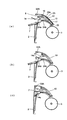
- the ion generation device 10 is of a cartridge type and is installed in an ion generation device housing portion provided in the main body of the device so that the ion generation device 10 is detachable and easy to replace. Therefore, in this embodiment, the ion generating device 10 is integrated with the insertion guide portion, the positioning guide portion, and the lever member 14 that locks and fixes the position of the ion generating device 10 to the engaging portion provided in the ion generating device accommodating portion on the main body side. As a cartridge type provided for the above, the ion generating surface is configured to be detachable through the lever member 14 so as to be exposed to the flow surface side.
- the ion generation device 10 is a cartridge type and is detachable so that the ion generation surface matches the flow surface forming the flow path, the ion generation is provided with a positive ion generation unit and a negative ion generation unit.
- the surface is preferably shaped to match the flow surface.
- the plus and minus ion generation units include a plus ion generation unit and a minus ion generation unit that are spaced apart from each other in a direction intersecting the flow direction.
- the ion generation surface of the ion generator 10 is a curved surface that matches the flow surface of the curved lower transverse wind direction plate 22A. It is preferable.
- an ion generator 10 that is a cartridge type that integrally includes an insertion guide portion, a positioning guide portion, and a lever member 14 that is locked and fixed to a locking portion provided in the ion generator housing portion on the main body side, By inserting from the insertion port 6 provided in the front of the apparatus and mounting the ion generation surface exposed to the flow surface from the outside of the flow path, the ion generation surface matches the flow surface and the air flow Without disturbing the air, the ions can be included in the air flowing through the flow path.
- the positive and negative ions generated at the positive and negative ion generators provided on the ion generation surface can be sent along the laminar flow on the flow surface of the flow path without confusion. It becomes.
- the ion generator housing part is provided in the lower side wind direction plate 22A that forms the lower wall surface of the flow path, the laminar flow formed on the lower wall surface is used to stabilize positive and negative ions in the horizontal direction. Can be sent out.
- the cartridge-type ion generation is performed from the insertion port 6 provided at the lower part of the outlet 4 by providing the ion generating device accommodating portion in the apparatus main body on the lower side of the flow passage of the lower side wind direction plate 22A.
- the apparatus 10 can be inserted to be detachable from the outer side of the lower transverse wind direction plate 22A to the posture where the ion generation surface is exposed to the flow surface.
- the ion generation surface may be used as a part of the flow surface of the horizontal wind direction plate 22, It can be realized by installing the ion generator 10 in parallel with the horizontal wind direction plate 22 or by installing the ion generator 10 by cutting out a part of the flow surface of the horizontal wind direction plate 22. Therefore, in the present embodiment, a notch portion 22a (see FIG. 2A) that exposes the ion generation surface is provided in the lower side wind direction plate 22A, and the ion generation surface of the ion generator 10 is exposed in this notch portion.
- the configuration is provided in the lower side wind direction plate 22A, and the ion generation surface of the ion generator 10 is exposed in this notch portion.
- the ion generator 10 is configured to include a positive and negative electrode pair of a positive ion generating electrode and a negative ion generating electrode, each of which performs plasma discharge, the positive ion and the negative ion are uniformly sent far away in the room. In order to make it possible, in order to prevent the generated positive ions and negative ions from colliding with each other and neutralizing, it is preferable to carry them through different flow paths.
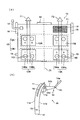
- the ion diffusing apparatus 1 has a horizontally long apparatus main body 2, and a plurality of ion generators 10 (10A, 10B, 10C, 10D) are disposed therein.
- the configuration in order to send out the ion which these ion generators generate
- FIG. 1 (b) in order to send out the ion which these ion generators generate
- the ion generators 10 including a positive ion generator and a negative ion generator are provided in a line, so that positive ions A generation
- production part can be arrange
- the vertical airflow direction plates 21 21a to 21j that partition the flow paths for the respective ion generators are provided, and different flow paths are provided. It sends out in the flow path.
- each vertical wind direction plate can be angled and blown into the room at a wide angle.
- the angle of the vertical wind direction plate 21d in the middle is set to 0, the angle is gradually increased toward the outside, and the angle of the vertical wind direction plates 21a and 21j at both ends is set to a large angle toward the outside, thereby blowing out at a wide angle.
- the vertical wind direction plates 21a to 21j that partition the positive and negative ion generation sections of the ion generators 10A, 10B, 10C, and 10D are larger as the outer vertical wind direction plates.
- a flow path that opens and blows out at a wide angle can be formed.
- the ions generated in the respective ion generators can be sent out without colliding with adjacent ions of different polarities, so that they can be sent out even far into the room.
- the ion generator having a double electrode type in which the plus ion generating electrode and the minus ion generating electrode are respectively provided in close proximity to each other in two stages is arranged in two stages, respectively.
- the inventors have found that when the ion concentration is 7,000 / cm 3 at the laboratory level, 99% of the avian influenza virus can be removed in 10 minutes and 99.9% at 50,000 / cm 3 . discovered.
- the meaning of both removal rates indicates that 10 / cm 3 and 1 / remain, respectively, assuming that 1,000 viruses / cm 3 virus were present in the air. That is, by increasing the ion concentration from 7,000 / 50,000 to 50,000 /, the remaining virus becomes 1/10. For this reason, it is very important not only to send out high-concentration ions in living spaces and work spaces where people live, but also to increase the ion concentration throughout the space in preventing infections and purifying the environment. It turns out that it is.
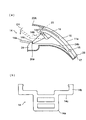
- the ion generation cartridge 10 shown in FIG. 4 includes an ion generator 12A including a double electrode type positive ion generation unit 13A and a negative ion generation unit 13B, a double electrode type negative ion generation unit 13B, and a positive ion generation unit 13A. Is a two-stage ion generator type provided in parallel with two stages of ion generators 12B.
- Each of the positive and negative ion generation electrodes is provided with a needle-like discharge electrode HD, and generates plasma by performing plasma discharge with the surrounding plate-like induction electrode. Further, if each discharge electrode HD is a double electrode type, the positive ion generation part 13A includes two electrodes, positive ion generation electrodes 13Aa and 13Ab, and the negative ion generation part 13B includes two negative ion generation electrodes 13Ba and 13Bb. Since each electrode is provided, the discharge amount is doubled, and a predetermined amount or more of ions can be stably generated.
- ions sent out by the air flow F1 are ions. While the generator 12A is operating, positive ions are sent out, and while the ion generator 12B is operating, negative ions are sent out.
- the ions delivered by the air flow F2 are configured such that the ion generator 12A operates to send negative ions, and the ion generator 12B operates to send positive ions.
- ions having opposite polarities are intermittently sent, and when viewed on a time average basis, positive ions and negative ions are equally distributed in the respective flow paths. Can be released.
- one ion generation cartridge 10 operates the two ion generators 12A and 12B alternately, the lifetime as the ion generation cartridge 10 is doubled and can be used for a long period of time.
- the position of the vertical wind direction plate 21 that divides the flow path for each ion generator may be any position where the air flow F1 and the air flow F2 can be partitioned, and generates a parallel air flow. If it is a blower, it can also be installed from the front end part vicinity of the ion generation cartridge 10. FIG.
- the ion generation cartridge 10 has a frame 11 having a rectangular shape in plan view when the ion generation surface from which the positive ion generation unit 13A and the negative ion generation unit 13B are exposed is viewed from above. As shown in FIG. 4B, the ion generation surface 11a is a curved surface that matches the flow surface.
- the frame 11 is connected to an external power source and inputs / outputs signals, and an input / output connector unit 19 that generates a predetermined discharge voltage from the electric power obtained through the input / output connector unit.
- Ion generators 12A and 12B and an ion sensor 18 for detecting ions generated by the ion generator are provided.
- a lever member 14 having a handle portion that is gripped when the cartridge is inserted and removed and a hook portion that is fixed to a predetermined position after insertion is mounted, and a guide function is exhibited at the side portion of the frame 11 of the cartridge when the cartridge is inserted.
- a guide protrusion 15, a contact surface 17, and a guide surface 16 are provided.
- the lever member 14 is rotatably mounted on the frame frame 11c on the back surface 11b of the frame body 11 via a shaft support portion 14d.
- the ion sensor 18 is a negative ion detection sensor that is provided in the vicinity of the downstream side of the negative ion generator 13B of the ion generator 12A and detects negative ions generated from the negative ion generator 13B.
- the ion current output according to the negative ion concentration captured by the electrode capturing the ions can be detected by converting to a voltage, but is not particularly limited to this type, and more than a predetermined amount
- An ion sensor having a function of detecting that negative ions are generated can be used.
- the positive ion generator 13A constantly generates positive ions, and the negative ion generator 13B always generates negative ions.
- the generated positive and negative ions are substantially the same amount, and the amount of one ion during the operation of the ion diffusion device is reduced.
- the guide protrusion 15 provided on the side of the frame 11 of the ion generating cartridge 10 abuts on a guide frame 24b (see FIG. 3A) that forms the ion generating device accommodating portion when the cartridge is inserted.
- the ion generating cartridge 10 is pushed in while the guide protrusions 15 on both sides of the frame 11 are in contact with the guide frames on both sides.
- the contact surface 17 is a portion that becomes a tip surface of the frame 11 when the ion generating cartridge 10 is mounted in the ion generating device accommodating portion, and is in contact with the accommodating portion frame 25 that forms the ion generating device accommodating portion. The surface to be positioned.
- the guide surface 16 abuts against the back frame 23 of the lower lateral wind direction plate 22A when the hook portion 14c of the lever member 14 is locked to a locking portion 24a (see FIG. 3A) and fixed in place.
- the surface to be positioned In this way, the contact surface 17 that defines the insertion end position and the guide surface 16 that defines the fixed position serve as a positioning guide portion.
- the ion generating device accommodating portion that accommodates the ion generating cartridge 10 is formed inside the insertion port 6, the accommodating portion frame 25 that restricts the insertion end of the cartridge, and the guide that restricts the side portion of the cartridge.
- the frame 24b, a notch 22a that exposes the ion generation surface of the cartridge, a back frame 23 that restricts the fixing position of the cartridge, and a locking portion 24a are provided, depending on the number of ion generation cartridges 10 installed.
- each ion generator housing portion is disposed.
- the lever member 14 is rotatably mounted on the ion generating cartridge 10 via a shaft support portion 14d, and includes an arm 14b and a handle portion 14a that is gripped when the cartridge is inserted and removed. After that, a hook portion 14c that is locked and fixed to a locking portion provided on the main device side is provided.
- the handle portion 14a can be gripped and rotated in the direction of the arrow D1 in the drawing, so that the hook portion 14c can be locked and locked to a locking portion 24a provided on the main body side.
- the handle portion 14a extends from the arm 14b on which the shaft support portion 14d is formed, bent at a predetermined angle to facilitate operation. Moreover, the hook part 14c should just be provided in either of the lever members 14 to rotate, and can be provided in the said arm 14b or the handle part 14a. In the present embodiment, as shown in FIG. 3 (b), the handle portion 14a protrudes from the arm 14b in a convex shape, and a portion corresponding to the distal end portions of the arms 14b on both sides of the handle portion 14a An arcuate hook portion 14c that is locked to a locking portion 24a formed on the apparatus-side frame 24 is provided.
- the hook portion 14c is formed in the middle portion of the lever member 14, and the lever portion 14 is rotated by holding the handle portion 14a provided on the distal end side of the lever member 14 to be locked.
- the operation of locking and fixing the position to the portion 24a and the operation of releasing the hook portion 14c from the locking portion 24a and releasing the force are less than the fitting resistance force between the hook portion 14c and the locking portion 24a. And can be easily operated.
- the lever member 14 including the handle portion 14a that is gripped when the cartridge is inserted and removed and the hook portion 14c that is fixed to a predetermined position after the cartridge is inserted is attached to the side of the cartridge frame when the cartridge is inserted.
- the opening / closing cover 7 is opened to open the insertion port 6, and the ion generation cartridge 10 is inserted from the opened insertion port 6.
- the lever member 14 is gripped and inserted until the contact surface 17 abuts against the accommodating portion frame 25. Further, the guide projection 15 slides on the guide frame 24b during the insertion operation.
- the ion generating cartridge 10 can be fitted into the notch portion 22a provided on the lower side wind direction plate 22A by an operation of pushing down the lever member 14 and locking the hook portion 14c with the locking portion 24a on the main unit side. Further, the guide surface 16 provided on the side surface of the frame of the ion generating cartridge 10 is in contact with the back surface frame 23 of the lower horizontal wind direction plate 22A so that the fitting posture is defined.
- the ion generation surface of the ion generation cartridge 10 is exposed to the notch 22a. Fix it.
- This posture is a posture exposed by matching the ion generation surface with the flow surface, and ions generated on the ion generation surface can be reliably discharged into the air flow.
- the opened opening / closing cover 7 can be closed.
- the opening / closing cover 7 to be closed interferes with the handle portion 14a of the lever member 14. If it is this structure, the closing of the opening-and-closing cover 7 can be prevented using the lever member 14 which is not in a regular position.
- the lever member 14 obstructs the closing of the opening / closing cover 7 so that it can be easily confirmed whether or not the ion generating cartridge 10 is correctly mounted.
- the input / output connector portion 19 is connected to a connection terminal provided in the main body device, and the mounting operation of the ion generating cartridge 10 is completed.
- the blower 3 to be used is the plurality of ion generation cartridges.
- a cross-flow blower having a fan length that blows air toward the row in which the air flow is disposed is preferable. If it is a cross flow blower, it is suitable as a blower used for the ion-diffusion apparatus 1 installed in the living space in which the quietness is high and it can drive
- the flow path divided into the several laminar flow path is divided into the lower side wind direction board 22A and the next 2nd side wind direction board 22B of the inner peripheral side near a cross flow fan.
- the wind speed K1 of the first passage 4A on the inner peripheral side is set to the slowest wind speed
- the wind speed K4 of the flow path can be made the fastest. If it is this structure, since the slowest 1st flow path 4A will convey the ion which the ion generator (ion generation cartridge) 10 generate
- each flow passage changes by adjusting the gap between the horizontal wind direction plates of the upper and lower horizontal wind direction plates and the intermediate horizontal wind direction plate, and by adjusting the number of rotations of the cross flow blower. Can be made.
- the operation stop operation part 8 (refer FIG.1 (b)) for driving the ion-diffusion apparatus 1 by operating a crossflow blower is provided in the front side of the apparatus main body.
- an operation mode setting unit for setting the rotation speed of the crossflow blower and a cartridge mounting time for setting that a new ion generating cartridge is mounted are included in the operation stop operation unit 8.
- a setting section, a timer setting section, a replacement recommendation display section for recommending cartridge replacement after a predetermined time has elapsed after installing a new ion generation cartridge, and a predetermined amount of ions generated by each ion generation cartridge A level display unit that displays whether the above or below can be provided.
- the ion generation cartridge has a predetermined usage time, it is recommended to replace it by setting the fact that a new ion generation cartridge is installed when a new cartridge is installed, and from the elapsed time due to subsequent use of the apparatus.
- a display can be made to notify that the replacement time is approaching. Further, when the number of ions generated during use of the apparatus is less than or equal to a predetermined amount, this is displayed, so that it can be known that maintenance of the ion generation unit is necessary.
- the ion generating device has a curved surface whose ion generating surface matches the flow surface of the wind direction plate, and the insertion guide portion, the positioning guide portion, and the locking portion on the device main body side.
- the ion diffusion device has a configuration in which a vertical wind direction plate is provided in the flow path for delivering ions to separate the flow paths for each of the positive and negative ion generation sections, so that positive ions and negative ions are generated evenly.
- the ion generator includes a double-electrode type positive ion generation unit and a negative ion generation unit each having two ion generation electrodes provided close to each other and an ion generation cartridge including an ion sensor, plus and minus It is easy to handle as a cartridge-type ion generator that generates a large amount of ions, and it can be easily confirmed whether or not it is operating normally. Therefore, an easily replaceable ion generating cartridge can be obtained.
- the ion generator having the double electrode type ion generation unit is a two-stage ion generator type ion generation cartridge arranged in two stages with the polarity of the ion generation electrode of the ion generation unit reversed, the same air Both positive and negative ions can be released into the flow at the same time or intermittently at predetermined discharge intervals to mix both positive and negative ions at a predetermined density.
- the passage from the blower to the outlet is divided into a plurality of laminar passages, the laminar passage for sending ions is the slowest bottom passage, and a fast laminar passage is formed in order on it. Since the configuration is adopted, it is possible to form an air wall that prevents diffusion of ions and to form a predetermined space that maintains the ion concentration. Furthermore, by using a cross-flow blower as the blower, it is possible to obtain an ion diffusion device that is highly silent and can be operated from a light breeze region and is suitable for a living space where quiet operation is required.
- the target where the ion diffusing apparatus of the present embodiment is installed is not limited to a living room, and may be a room where an unspecified person stays for a certain period of time (for example, a waiting room of a station or a hospital, a hall, a classroom, etc.). . Moreover, if the ventilation rate is below a certain level, the room may be opened by a window or ventilated by a ventilator. Moreover, the room air-conditioned by the air conditioner may be used. Furthermore, by arranging a plurality of ion diffusing devices of this embodiment at intervals, a sufficient ion concentration can be ensured in a wide area of a non-partitioned space (for example, a lobby of a hotel, airport, etc.).
- the ion diffusing device and the ion generating cartridge according to the present invention serve as an ion diffusing device capable of maintaining a high concentration of positive and negative ions remaining in the living space, and an ion generating cartridge that is easy to maintain. It becomes possible to use suitably for the ion diffusion apparatus for ensuring the living space of a person.
Landscapes
- Engineering & Computer Science (AREA)
- Health & Medical Sciences (AREA)
- General Health & Medical Sciences (AREA)
- Mechanical Engineering (AREA)
- General Engineering & Computer Science (AREA)
- Combustion & Propulsion (AREA)
- Chemical & Material Sciences (AREA)
- Toxicology (AREA)
- Epidemiology (AREA)
- Life Sciences & Earth Sciences (AREA)
- Animal Behavior & Ethology (AREA)
- Public Health (AREA)
- Veterinary Medicine (AREA)
- Disinfection, Sterilisation Or Deodorisation Of Air (AREA)
- Elimination Of Static Electricity (AREA)
Abstract
Description
2 装置本体
3 送風機
4 吹出口
5 吸込口
6 差込口
7 開閉カバー
8 運転停止操作部
10 イオン発生装置(イオン発生カートリッジ)
11a イオン発生面
12 イオン発生器
13A プラスイオン発生部
13Aa、13Ab プラスイオン発生電極
13B マイナスイオン発生部
13Ba、13Bb マイナスイオン発生電極
14 レバー部材
14a 取っ手部
14c フック部
15 ガイド突部
16 ガイド面
17 当り面
18 イオンセンサ
19 入出力コネクタ部
21 縦風向板
22 横風向板
22A 下部横風向板
22E 上部横風向板
Claims (18)
- プラズマ放電により発生させたプラスイオン及びマイナスイオンを室内に拡散させるイオン拡散装置において、
吸込口から吸い込んだ空気を、装置内に形成された通流路を通って吹出口から室内へ吹き出すための空気流を生成する送風機と、
プラスイオン発生部及びマイナスイオン発生部を有し、前記プラスイオン発生部から発生したプラスイオン及び前記マイナスイオン発生部から発生したマイナスイオンを前記通流路を通過する空気に含ませるイオン発生装置と、を設け、
前記通流路の壁面を形成する一面の通流面に合致させて、前記イオン発生装置のイオン発生面を露出する姿勢で、前記イオン発生装置を収容するイオン発生装置収容部を設け、
前記イオン発生装置を、前記吹出口側に設ける差込口から出し入れ可能とし、前記イオン発生装置収容部に着脱自在としたことを特徴とするイオン拡散装置。 - 前記一面が前記通流路の下部壁面を形成する下部横風向板から形成されたことを特徴とする請求項1に記載のイオン拡散装置。
- 前記イオン発生装置を、プラスイオン発生部及びマイナスイオン発生部を有するイオン発生器と、前記イオン発生器を収納すると共に挿入ガイド部と位置決めガイド部と、装置本体側の係止部に係止して位置固定するレバー部材を一体に備えるイオン発生カートリッジとし、
前記挿入ガイド部と位置決めガイド部を介して、前記イオン発生装置を前記差込口から挿入して前記イオン発生装置収容部まで押し込み、前記位置決めガイドと前記レバー部材を介して、前記イオン発生面を前記通流面に合致させた姿勢で固定する構成としたことを特徴とする請求項2に記載のイオン拡散装置。 - 前記イオン発生装置は、空気の通流方向に交差する方向にプラスイオン発生部及びマイナスイオン発生部を隔離するイオン発生器を含み、前記通流路に、プラスイオン発生部及びマイナスイオン発生部のそれぞれのイオン発生部毎の通流路に仕切る縦風向板を設けたことを特徴とする請求項3に記載のイオン拡散装置。
- 前記下部横風向板と通流路の上部壁面を形成する上部横風向板との間の通流路を仕切る中間横風向板を設けて、前記送風機から前記吹出口に至る通流路を複数段の層流通路に仕切ると共に、
前記下部横風向板の通流面に沿ってプラスイオン発生部及びマイナスイオン発生部を交互に所定ピッチで一列に備える長尺なイオン発生面を形成するように前記イオン発生装置を複数併設し、
それぞれのイオン発生部毎の通流路に仕切る前記縦風向板を前記複数段の層流通路を貫通するように配設したことを特徴とする請求項4に記載のイオン拡散装置。 - 前記縦風向板を、前記イオン発生装置を併設した幅方向に対して広角度に吹き出すようにそれぞれの縦風向板に角度を付けたことを特徴とする請求項5に記載のイオン拡散装置。
- 前記イオン発生カートリッジが、外部電極に接続して入出力を行う入出力コネクタ部と、該入出力コネクタ部を介して得られた電力によりプラスイオン発生部及びマイナスイオン発生部を所定間隔で駆動制御する制御基板と、前記イオン発生部にて発生されるイオンを検出するイオンセンサとを備えていることを特徴とする請求項3に記載のイオン拡散装置。
- 前記イオンセンサを、前記イオン発生カートリッジのマイナスイオン発生部の風下側に設置するマイナスイオン検知センサとしたことを特徴とする請求項7に記載のイオン拡散装置。
- 前記イオン発生器のプラスイオン発生部が備えるプラスイオン発生電極及びマイナスイオン発生部が備えるマイナスイオン発生電極とを、それぞれ二個の発生電極を近接して設けたダブル電極型としたことを特徴とする請求項3に記載のイオン拡散装置。
- 前記イオン発生カートリッジを、前記イオン発生器を二段に並列すると共に、それぞれのイオン発生器のプラスイオン発生電極とマイナスイオン発生電極を、その正負の極性を逆とした二段イオン発生器型としたことを特徴とする請求項9に記載のイオン拡散装置。
- 前記二段イオン発生器型イオン発生カートリッジのそれぞれの段のイオン発生器を交互に作動させることを特徴とする請求項10に記載のイオン拡散装置。
- 前記差込口を閉止・開放する開閉カバーを設け、前記イオン発生カートリッジを所定位置まで挿入して、前記レバー部材が有するフック部を本体側の係止部に係止させる固定ロック位置に前記レバー部材を回動したときに、前記開閉カバーの閉止を可能とし、前記レバー部材が固定ロック位置まで回動されていない状態では、前記レバー部材が前記開閉カバーの閉止を妨害することを特徴とする請求項3に記載のイオン拡散装置。
- 装置本体に運転停止操作部を設けると共に、該操作部に、前記送風機の回転速度を設定する運転モード設定部と、新たなイオン発生カートリッジを装着したことを設定するカートリッジ装着時期設定部と、タイマー設定部と、新たなイオン発生カートリッジを装着して運転開始後の所定時間経過後に、カートリッジ交換を推奨する交換推奨表示部と、それぞれのイオン発生カートリッジが発生するイオンが所定量以上か以下かを表示するレベル表示部とを配設したことを特徴とする請求項3から12のいずれかに記載のイオン拡散装置。
- プラズマ放電によりプラスイオン及びマイナスイオンを発生するイオン発生装置であって、
外部電源に接続すると共に信号の入出力を行う入出力コネクタ部と、プラスイオン発生電極とマイナスイオン発生電極とをそれぞれ設けたイオン発生器と、該イオン発生器が発生するイオンを検出するイオンセンサと、前記入出力コネクタ部を介して得られた電力によりイオン発生器を駆動制御する制御基板と、を備えたことを特徴とするイオン発生カートリッジ。 - 前記イオンセンサが、マイナスイオン発生電極から発生するマイナスイオンを検知するマイナスイオン検知センサであることを特徴とする請求項14に記載のイオン発生カートリッジ。
- カートリッジ挿脱時に把持する取っ手部と、挿入した後で所定位置に固定するフック部とを備えるレバー部材を装着し、カートリッジの枠体の側部に、カートリッジ挿入時にガイド機能を発揮するガイド突部と、当り面と、ガイド面を設けたことを特徴とする請求項14に記載のイオン発生カートリッジ。
- 前記イオン発生カートリッジが、正負のイオン発生電極が露出しているイオン発生面を上から見て平面視矩形状であって、前記イオン発生器を、そのイオン発生電極部の正負の極性を逆として二段に並列した二段イオン発生器型とすると共に、前記イオン発生面を前記イオン発生カートリッジが装着される通流面に合致した曲面としたことを特徴とする請求項14に記載のイオン発生カートリッジ。
- 前記二段イオン発生器型イオン発生カートリッジのそれぞれの段のイオン発生器を交互に作動させることを特徴とする請求項17に記載のイオン発生カートリッジ。
Priority Applications (2)
| Application Number | Priority Date | Filing Date | Title |
|---|---|---|---|
| KR1020117004517A KR101224699B1 (ko) | 2008-08-28 | 2009-08-27 | 이온 확산 장치 및 이온 발생 카트리지 |
| US13/056,894 US8625252B2 (en) | 2008-08-28 | 2009-08-27 | Ion diffusing apparatus and ion generating cartridge |
Applications Claiming Priority (2)
| Application Number | Priority Date | Filing Date | Title |
|---|---|---|---|
| JP2008-219848 | 2008-08-28 | ||
| JP2008219848A JP4551953B2 (ja) | 2008-08-28 | 2008-08-28 | イオン拡散装置 |
Publications (1)
| Publication Number | Publication Date |
|---|---|
| WO2010024318A1 true WO2010024318A1 (ja) | 2010-03-04 |
Family
ID=41721484
Family Applications (1)
| Application Number | Title | Priority Date | Filing Date |
|---|---|---|---|
| PCT/JP2009/064932 Ceased WO2010024318A1 (ja) | 2008-08-28 | 2009-08-27 | イオン拡散装置およびイオン発生カートリッジ |
Country Status (6)
| Country | Link |
|---|---|
| US (1) | US8625252B2 (ja) |
| JP (1) | JP4551953B2 (ja) |
| KR (1) | KR101224699B1 (ja) |
| CN (1) | CN201551620U (ja) |
| MY (1) | MY152310A (ja) |
| WO (1) | WO2010024318A1 (ja) |
Cited By (2)
| Publication number | Priority date | Publication date | Assignee | Title |
|---|---|---|---|---|
| CN103918145A (zh) * | 2011-11-11 | 2014-07-09 | 夏普株式会社 | 离子发生单元和电气设备 |
| CN104067697A (zh) * | 2012-02-28 | 2014-09-24 | 夏普株式会社 | 除电装置 |
Families Citing this family (18)
| Publication number | Priority date | Publication date | Assignee | Title |
|---|---|---|---|---|
| JP5284413B2 (ja) * | 2011-05-18 | 2013-09-11 | シャープ株式会社 | イオン発生装置 |
| JP5863404B2 (ja) * | 2011-11-10 | 2016-02-16 | シャープ株式会社 | ヘアケア装置 |
| US20130206738A1 (en) * | 2012-02-10 | 2013-08-15 | First Solar, Inc. | In situ inductive ablation meter |
| CN105650006A (zh) * | 2012-04-03 | 2016-06-08 | 夏普株式会社 | 送风装置、离子送出装置、电气设备以及遥控器保持结构 |
| KR101936749B1 (ko) * | 2012-09-28 | 2019-01-10 | 엘지전자 주식회사 | 이동식 이온 발생 장치 |
| JP2014154416A (ja) * | 2013-02-12 | 2014-08-25 | Sharp Corp | イオン発生装置及びこれを用いた除電器 |
| US9808547B2 (en) | 2013-04-18 | 2017-11-07 | Dm Tec, Llc | Sanitizer |
| US9950086B2 (en) | 2014-03-12 | 2018-04-24 | Dm Tec, Llc | Fixture sanitizer |
| US9700643B2 (en) | 2014-05-16 | 2017-07-11 | Michael E. Robert | Sanitizer with an ion generator |
| US9476603B2 (en) * | 2014-12-12 | 2016-10-25 | Dong Guan Song Wei Electric Technology Co., Ltd | Heater with humidifying device |
| US10124083B2 (en) | 2015-06-18 | 2018-11-13 | Dm Tec, Llc | Sanitizer with an ion generator and ion electrode assembly |
| FR3039407B1 (fr) * | 2015-07-30 | 2021-04-30 | Atelier Elio Sa | Dispositif de diffusion |
| US10265431B2 (en) * | 2017-06-08 | 2019-04-23 | Henkel IP & Holding GmbH | Volatile diffuser pods and related systems |
| US10907656B2 (en) * | 2018-02-04 | 2021-02-02 | Richard Down Newberry | Silent airflow generation equipment |
| JP7185550B2 (ja) * | 2019-02-12 | 2022-12-07 | シャープ株式会社 | 送風装置 |
| KR102609063B1 (ko) * | 2022-03-14 | 2023-12-01 | 왕태철 | 연속공급을 위한 리던던시 기능을 갖는 플라스마 발생기 |
| CN119901014B (zh) * | 2023-10-20 | 2025-12-09 | 宁波奥克斯电气有限公司 | 一种可均匀出风的离子风空调组件 |
| WO2026036005A1 (en) * | 2024-08-09 | 2026-02-12 | Illinois Tool Works Inc. | Methods and apparatus for ionizing blowers having angled/rotatable collimation |
Citations (7)
| Publication number | Priority date | Publication date | Assignee | Title |
|---|---|---|---|---|
| JP2004363088A (ja) * | 2003-05-15 | 2004-12-24 | Sharp Corp | イオン発生素子、イオン発生装置、電気機器 |
| JP2005156027A (ja) * | 2003-11-26 | 2005-06-16 | Sharp Corp | 空気調和機、ファンヒータおよび抗原性物質を失活させる方法 |
| JP2006170476A (ja) * | 2004-12-13 | 2006-06-29 | Sharp Corp | イオン発生装置及びこれを備えた空気調節装置 |
| JP2007287368A (ja) * | 2006-04-13 | 2007-11-01 | Koganei Corp | 除電装置および放電モジュール |
| JP2007335092A (ja) * | 2006-06-12 | 2007-12-27 | Sharp Corp | イオン発生装置およびこれを備えた空気調整装置 |
| JP2008059795A (ja) * | 2006-08-29 | 2008-03-13 | Sharp Corp | イオン発生装置 |
| JP2008192556A (ja) * | 2007-02-07 | 2008-08-21 | U-Tec Kk | イオン発生器 |
Family Cites Families (1)
| Publication number | Priority date | Publication date | Assignee | Title |
|---|---|---|---|---|
| JP4114602B2 (ja) | 2003-12-08 | 2008-07-09 | マックス株式会社 | 空気処理装置及びイオン発生装置並びに空調装置並びに建物 |
-
2008
- 2008-08-28 JP JP2008219848A patent/JP4551953B2/ja not_active Expired - Fee Related
-
2009
- 2009-08-24 CN CN2009201701681U patent/CN201551620U/zh not_active Expired - Lifetime
- 2009-08-27 MY MYPI20110309 patent/MY152310A/en unknown
- 2009-08-27 KR KR1020117004517A patent/KR101224699B1/ko not_active Expired - Fee Related
- 2009-08-27 WO PCT/JP2009/064932 patent/WO2010024318A1/ja not_active Ceased
- 2009-08-27 US US13/056,894 patent/US8625252B2/en not_active Expired - Fee Related
Patent Citations (7)
| Publication number | Priority date | Publication date | Assignee | Title |
|---|---|---|---|---|
| JP2004363088A (ja) * | 2003-05-15 | 2004-12-24 | Sharp Corp | イオン発生素子、イオン発生装置、電気機器 |
| JP2005156027A (ja) * | 2003-11-26 | 2005-06-16 | Sharp Corp | 空気調和機、ファンヒータおよび抗原性物質を失活させる方法 |
| JP2006170476A (ja) * | 2004-12-13 | 2006-06-29 | Sharp Corp | イオン発生装置及びこれを備えた空気調節装置 |
| JP2007287368A (ja) * | 2006-04-13 | 2007-11-01 | Koganei Corp | 除電装置および放電モジュール |
| JP2007335092A (ja) * | 2006-06-12 | 2007-12-27 | Sharp Corp | イオン発生装置およびこれを備えた空気調整装置 |
| JP2008059795A (ja) * | 2006-08-29 | 2008-03-13 | Sharp Corp | イオン発生装置 |
| JP2008192556A (ja) * | 2007-02-07 | 2008-08-21 | U-Tec Kk | イオン発生器 |
Cited By (4)
| Publication number | Priority date | Publication date | Assignee | Title |
|---|---|---|---|---|
| CN103918145A (zh) * | 2011-11-11 | 2014-07-09 | 夏普株式会社 | 离子发生单元和电气设备 |
| US9125961B2 (en) | 2011-11-11 | 2015-09-08 | Sharp Kabushiki Kaisha | Ion generating unit and electric device |
| CN103918145B (zh) * | 2011-11-11 | 2016-03-09 | 夏普株式会社 | 离子发生单元和电气设备 |
| CN104067697A (zh) * | 2012-02-28 | 2014-09-24 | 夏普株式会社 | 除电装置 |
Also Published As
| Publication number | Publication date |
|---|---|
| MY152310A (en) | 2014-09-15 |
| KR20110050477A (ko) | 2011-05-13 |
| US20110133098A1 (en) | 2011-06-09 |
| US8625252B2 (en) | 2014-01-07 |
| KR101224699B1 (ko) | 2013-01-21 |
| JP2010055946A (ja) | 2010-03-11 |
| CN201551620U (zh) | 2010-08-18 |
| JP4551953B2 (ja) | 2010-09-29 |
Similar Documents
| Publication | Publication Date | Title |
|---|---|---|
| JP4551953B2 (ja) | イオン拡散装置 | |
| JP4718639B2 (ja) | イオン発生カートリッジ | |
| CN101658689B (zh) | 净化室内的方法 | |
| JP4740663B2 (ja) | 殺菌方法、殺菌装置及びこれを用いたイオン発生装置、電気機器、空気浄化装置 | |
| JP2003284766A (ja) | イオン発生装置を備えた表示装置、および電子装置 | |
| WO2010023980A1 (ja) | イオン発生装置及び空気清浄装置 | |
| JP2010017520A (ja) | 空気清浄機 | |
| US20180147312A1 (en) | Ventilation Duct to Eradicate Indoor Odor and Microbes | |
| JP5150412B2 (ja) | イオン拡散装置 | |
| JP2005076906A (ja) | 空気調節装置 | |
| JP2010075664A (ja) | イオン発生装置及び空気清浄装置 | |
| CN218120100U (zh) | 用于空调器的空气调节装置 | |
| JP4163540B2 (ja) | 換気装置並びにこれを用いた建物 | |
| KR20120036214A (ko) | 공기제균장치 및 이를 이용하는 공기정화방법 | |
| JP3051083B2 (ja) | 空気清浄機 | |
| JP4223306B2 (ja) | 給気口構造及び換気システム及びこれを用いた建物 | |
| KR20070036763A (ko) | 피에이치아이 모듈을 적용한 조립식 환기유니트 | |
| JP4913705B2 (ja) | 給気口構造及び換気システム及びこれを用いた建物 | |
| KR102222474B1 (ko) | 비말 내 부유 미생물 살균기 | |
| JP5087121B2 (ja) | 給気口構造及び換気システム及びこれを用いた建物 | |
| JP4690111B2 (ja) | 換気装置 | |
| JP2006132842A (ja) | 換気装置及び換気システム並びに住宅構造 | |
| CN218884198U (zh) | 空气净化设备 | |
| WO2010119733A1 (ja) | イオン発生装置及び空気清浄装置 | |
| JP2004103279A (ja) | 空気浄化機能付き照明器具 |
Legal Events
| Date | Code | Title | Description |
|---|---|---|---|
| 121 | Ep: the epo has been informed by wipo that ep was designated in this application |
Ref document number: 09809968 Country of ref document: EP Kind code of ref document: A1 |
|
| WWE | Wipo information: entry into national phase |
Ref document number: 13056894 Country of ref document: US |
|
| ENP | Entry into the national phase |
Ref document number: 20117004517 Country of ref document: KR Kind code of ref document: A |
|
| WWE | Wipo information: entry into national phase |
Ref document number: 1367/CHENP/2011 Country of ref document: IN |
|
| NENP | Non-entry into the national phase |
Ref country code: DE |
|
| 122 | Ep: pct application non-entry in european phase |
Ref document number: 09809968 Country of ref document: EP Kind code of ref document: A1 |