WO2010024047A1 - 塗装ブース - Google Patents
塗装ブース Download PDFInfo
- Publication number
- WO2010024047A1 WO2010024047A1 PCT/JP2009/062427 JP2009062427W WO2010024047A1 WO 2010024047 A1 WO2010024047 A1 WO 2010024047A1 JP 2009062427 W JP2009062427 W JP 2009062427W WO 2010024047 A1 WO2010024047 A1 WO 2010024047A1
- Authority
- WO
- WIPO (PCT)
- Prior art keywords
- gas
- painting
- opening
- passage
- door
- Prior art date
- Legal status (The legal status is an assumption and is not a legal conclusion. Google has not performed a legal analysis and makes no representation as to the accuracy of the status listed.)
- Ceased
Links
Images


Classifications
-
- B—PERFORMING OPERATIONS; TRANSPORTING
- B05—SPRAYING OR ATOMISING IN GENERAL; APPLYING FLUENT MATERIALS TO SURFACES, IN GENERAL
- B05B—SPRAYING APPARATUS; ATOMISING APPARATUS; NOZZLES
- B05B16/00—Spray booths
- B05B16/60—Ventilation arrangements specially adapted therefor
Definitions
- the present invention relates to a painting booth that enables painting of objects such as automobiles and trains in a clean environment.
- Patent Documents 1 and 2 disclose a painting booth that performs vertical push-pull ventilation in which the painting space is ventilated by a downward airflow generated by the power supply means and the power exhaust means. Has been.
- air is supplied into the painting space from almost the entire area of the ceiling surface that is wider than the size of the object to be painted in plan view, while the floor surface portion that is wider than the size of the object to be painted in plan view is drawn.
- the gas in the painting space flows out from substantially the entire area, thereby ventilating the coating space in layers.
- a painting booth in which horizontal push-pull ventilation is performed, in which a horizontal air flow is generated by the power supply means and the power exhaust means, and the painting space is ventilated by the horizontal air flow, It is possible to do.
- Patent Document 3 shows a painting booth where horizontal push-pull ventilation is performed.
- This painting booth is used to carry in and out the object to be painted on the surrounding wall that surrounds the side of the painting space between the air supply port of the power supply means and the exhaust port of the power exhaust means. Since the opening is formed, an automobile or a train must be set from the side of the painting space. Traveling vehicles such as automobiles and trains are long in the front-rear direction and must be ventilated over a large area at the air supply and exhaust ports.
- a gas passage 8A in the door is provided at both ends in the width direction on the upper side of the opening / closing port 4 of the painting space 100a.
- a horizontal airflow is generated in the painting space 100a by being supplied into the painting space 100a through 8A and exhausted outward from the painting space 100a by the power exhaust means 40, and the airflow is applied to the painting space 100a.
- the present invention does not require pits and the like, and provides a painting booth that can perform solvent-based painting of elongated objects such as automobiles and trains while ventilating the painting space with relatively little energy. It is intended to provide.
- the present invention forms a push-pull ventilation passage in which a ventilation port portion is horizontally opposed to a painting space surrounded by upper, lower, left and right side wall surfaces, and gas is pumped and sucked between them.
- the other vent is also provided on the opposite side of the door, When the open / close door is closed, a push-pull ventilation passage is formed through the gas passage opening, the gas passage opening, the internal passage, the one ventilation opening, the painting space, and the other ventilation opening. It is characterized by doing.
- an elongated traveling vehicle such as an automobile or a train is opened from the opening / closing port in a state where the traveling direction (in most cases, the longitudinal direction) is aligned with the direction of the horizontal airflow. Even if the painting space is not wide enough to change the direction of an elongated object such as an automobile or a train by carrying it into the painting space, the longitudinal direction of the object is horizontal. In addition, when painting is completed, the object to be painted can be taken out from the painting space through the opening / closing port without any trouble.
- the cross-sectional area of the ventilation passage in the painting space during painting is narrower to the extent that it is larger than the projected area of the front and rear surfaces of the traveling vehicle, it can be performed with relatively little energy. Equipment costs can be reduced by reducing the capacity of exhaust fans, burners, coolers, etc. Furthermore, since the ventilation in the painting space is performed with a horizontal airflow, there is no need to provide a pit for ventilation on the floor surface of the painting space, and it can be constructed in a short period of time and at a low cost.
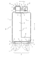
- FIG. 1 is a side view showing a first embodiment of a painting booth according to the present invention
- FIG. 2 is a plan view of the painting booth
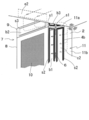
- FIG. 3 is a view of an opening / closing door
- FIG. 4 is a perspective view of the opening / closing door. is there.
- the painting booth of this embodiment is used for repair painting of automobiles, and includes a box-shaped main body 100, an air supply unit 101, and an exhaust unit 102 as shown in FIGS.
- 1 is a horizontal floor surface
- 2 is a vertical wall surrounding the side
- 3 is a horizontal zenith surface covering the top surface.
- the inner space of the surrounding wall 2 is a sealed painting space 100a.
- a rectangular first opening / closing port 4 through which an object (car, train, etc.) w is carried in and out of the painting space 100a is formed on the front surface of the surrounding wall 2, and a painting space is formed on the side surface of the surrounding wall 2.
- the 2nd opening-and-closing port 5 for an operator to go in and out with respect to 100a is formed.
- the painting space 100a is set to the minimum necessary size that can accommodate and paint the workpiece w.
- the planned painting object w is a traveling vehicle such as an automobile or a train.
- the dimension in the left-right direction f1 is about 4 m
- the dimension in the front-rear direction f2 is about 7 to 10 m
- the height is about 3 m.
- the first opening / closing port 4 includes a rectangular opening 4a (FIG. 2) formed in the surrounding wall 2 and two door bodies 7a provided in the inside thereof via a hinge 6 (FIG. 3). 7b.
- the two door bodies 7a and 7b are positioned in a single plane and close the opening 4a in an airtight manner, or are swung around the vertical axis along the left and right side edges 4b and 4b of the opening 4a. 2 is opened in a double-spread form as indicated by a virtual line a1.
- Each door body 7a, 7b has a flat box shape.
- a relatively wide space on the inner lower side serves as a gas passage 8 in the door, and a relatively narrow space on the inner upper side serves as a gas side passage 9. ing.
- the gas passage 8 in the door has a vent portion (air supply port portion) 10 that can be vented on the rear surface, and a gas passage port portion b1 is formed in a substantially full height range of a side surface on the hinge 6 mounting side of the outer peripheral surface.
- the other front and outer peripheral surfaces are surrounded by plate members, and the gas flowing into the door gas passage 8 from the gas passage port b1 flows out from the entire surface of the vent port 10 at a uniform flow rate.
- the vent portion 10 includes a lattice surface member 10a fixed to the rear edge of the outer peripheral member of the gas passage 8 in the door so as to cover the entire inner surface thereof, and a filter attached to the entire front surface of the lattice member 10a.
- each door body 7a, 7b has a box shape that is long in the left-right direction f1, and is outside except for the gas inlet port b2 on the rear surface and the gas passage port portion b3 on the side surface on the hinge 6 mounting side.
- the periphery is hermetically surrounded by plate members.
- a vertical front gas passage 11 extending over the entire height range of the surrounding wall 2 is formed on the left and right sides of the first opening / closing port 4 on the front surface of the surrounding wall 2.
- This longitudinally front gas passage 11 includes a longitudinal longitudinal surface 11a located on the center side of the body portion width, a lateral longitudinal surface 11b located on the rear side, a curved longitudinal surface 11c surrounding the front side and the lateral outer side, an upper end surface, and
- Each of the lower end surfaces is provided with a vertically long space surrounded by a plate member in an airtight manner, and a gas communication port c1 is formed in a lateral position of the gas horizontal passage 9 at the upper part of the longitudinal surface 11a in the front-rear direction and the gas communication port It is set as the structure by which the gas passage opening part c2 over the substantially full height range of the gas passage 8 in a door was formed in the lower side of the part c1.
- the gas passage c1 is airtight through a seal member s1 such as packing to the gas passage port b3 of the gas lateral passage 9.
- the gas passage c2 is connected to the gas passage port b1 of the door gas passage 8 via a seal member s2 such as packing. It is designed to communicate in an airtight manner.
- a gas guide plate (not shown) is installed to allow the gas in the vertically front gas passage 9 to flow evenly into the entire height range in the door gas passage 8 as necessary.
- a square planar vent hole portion (exhaust port portion) 12 is formed on the rear surface portion of the surrounding wall 2.
- This vent portion 12 is parallel to the plane formed by the two vent portions 10 and faced in the same shape, and has a rectangular planar opening 12a formed in the rear surface portion of the surrounding wall 2 and an inner side of the opening 12a.
- the grid member 12b is fixed so as to cover the entire surface, and the filter 12c is attached to the entire front side of the grid member 12b.
- An exhaust chamber 14 that surrounds the entire rear surface of the vent portion 12 with the floor surface 1 and the plate member 13 is formed on the rear side of the vent portion 12.
- the exhaust chamber 14 has a front space d1 that has substantially the same size as the vent portion 12 and is covered with the vent portion 12, and a front side space d1 that is continuous with the front space d1 and on one side behind the front space d1.
- a rear space d2 which is located on the floor surface 1 and whose height is about half of the front space d1.
- a duct (referred to as an upper duct) 15 is formed horizontally on the zenith surface 3.
- the upper duct 15 has a ventilation portion 15a having a width that is substantially half the width of the main body portion 100 in the front-rear direction f2, and a ventilation portion 15b that communicates with the ventilation portion 15a and has a size over the entire length of the main body portion 100. It is made up of.
- a part of the rear end surface (upper side in FIG. 2) of the ventilation portion 15a is opened to form a gas port e1. Further, the front end surface (lower side of the drawing in FIG.
- each door 7a is closed, each gas passage opening e2 is sealed with a seal such as packing on the gas passage opening b2 of the corresponding gas side passages 9, 9. It communicates in an airtight manner via the member s3.
- FIGS. 1 and 2 17 is an air supply fan, 18 is a burner installation passage portion, and 19 is an air supply duct.
- the air supply fan 17 pumps gas to the painting space 100, and is a path for introducing outside air from the outside air filter 21 via the damper 22 and a path for introducing gas from the exhaust unit 102 described later via the damper 33. And a path to be introduced from the cooling path 38 from the cooler 23 through the damper circulation 37.
- the air supply fan 17 sends these gases to the cooler 23, and the cooler 23 cools and dehumidifies the gases and sends them to the burner installation passage 18.
- the air supply fan 17 is capable of obtaining an air volume of about 160 cubic meters per minute, and a rated output of about 3.7 kw is used.
- the burner 25 of the burner installation passage section 18 is for heating the gas sent from the air supply fan 17 with a thermal power such as gas fuel, and in this embodiment, has a capacity of about 80000 kcal / h.
- the air supply / delivery duct 19 is formed by communicating the gas outlet portion of the burner installation passage portion 18 with the gas inlet portion e1 of the upper air supply duct 15, and the gas flowing out of the burner installation passage portion 18 is allowed to flow through the upper duct 15. To flow into.
- Each part of the air supply unit 101 described above is installed in a space-saving manner immediately after the front space d1 at the lateral position of the rear space d2 of the exhaust chamber section 14.
- the exhaust fan 26 includes a fan device 29 fixed to a support frame 28 fixed on the floor surface 1 of the exhaust chamber portion 14, and an electric motor 30 fixed to the support frame 28 and driving the fan device 29. .
- an air volume of about 160 cubic meters per minute is obtained, and the electric motor 30 having a rated output of about 3.7 kW is used.
- the exhaust discharge cylinder 27 rises higher than the main body 100 from the upper surface plate of the rear space d2 of the exhaust chamber section 14, and the lower end communicates with the exhaust discharge port of the exhaust fan 26 in an airtight manner and the upper end is opened to the atmosphere side.
- a damper 31 is provided in the middle of the length.
- 32 is an exhaust passage for gas circulation control
- 33 is a damper provided in the middle of the length of the exhaust passage 32.
- one end of the exhaust passage 32 is communicated with the inner space of the exhaust upstream side of the damper 31 in the middle of the length of the exhaust discharge upright cylinder 27.
- 34 is a translucent part formed in the surrounding wall 2
- 35 is a translucent part of the door in which the second opening / closing port 5 is formed
- 36 is a smoke exhaust cylinder for releasing the combustion gas of the burner 25.
- the push-pull ventilation passage is formed with the two door bodies 7a and 7b closed again.
- the vent 10 and the vent 12 have at least the outer shape of the portion to be painted of the automobile w.
- the state is included in each of the twelve outer shape ranges. Further, the damper 22 and the damper 31 are opened, and the damper 33 is closed.
- the air supply fan 17 and the exhaust fan 26 are put into operation.
- the outside air has a relatively large flow rate (for example, about 160 cubic meters per minute), the outside air filter 21, the damper 22, the air supply fan 17, the burner installation passage portion 18, the gas delivery duct 19, the upper air supply duct 15, and the gas.
- the gas in the painting space 100a reaches the vent 12 when the gas is supplied to the painting space 100a via the horizontal passage 9, the vertical front gas passage 11, the gas passage 8 in the door, and the vent portion 10, the exhaust gas is exhausted.
- the vent portion 12 After passing through the vent portion 12 at a relatively large flow rate (for example, about 160 cubic meters per minute), it is discharged to the outside through the exhaust chamber portion 14, the exhaust fan 26, the damper 31, and the exhaust discharge upright cylinder 27. .
- ⁇ An operator enters the painting space 100a where the layered ventilation is performed and performs painting. At this time, harmful substances are emitted from the paint.
- the worker always places the emission source in the trapped air flow and prevents it from entering between the emission source and the vent portion 12. Specifically, the worker places the coating gun held in his / her hand in the captured airflow while being positioned outside the captured airflow range at the side in the painting space 100a, and directs the paint toward the portion to be painted of the automobile w. Either the spraying is performed, or the paint is sprayed from the coating gun by being positioned upstream of the captured airflow from the position of the coating gun held in the hand.
- the burner 25 When the paint on the painted surface of the object to be coated w is dried after the completion of the solvent-based coating, the burner 25 is operated under the ventilation state with the same air supply and exhaust flow rate as described above, and the painting space The supply air that passes through the burner installation passage portion 18 is heated so that the temperature of the supply air in 100a is maintained at, for example, about 80 ° C. As a result, the paint on the painted surface is efficiently dried. After the drying is completed, the two door bodies 7a and 7b are opened again, and the automobile as the object to be coated w is moved and moved in a straight line in the longitudinal direction by the rotation of its own traveling wheel. Take out the outside.
- the exhaust in the exhaust chamber 14 is caused to flow into the intake fan 17 at a flow rate of, for example, about 120 cubic meters per minute, and the opening degree of the damper 22 is reduced to supply outside air.
- the suction force of the air fan 17 allows the gas to flow simultaneously at a flow rate of, for example, about 40 cubic meters per minute, and then these gases sent by the air supply fan are cooled and dehumidified by the cooler 23 and heated by the burner 25 every minute.
- the flow of about 160 cubic meters is made to flow into the painting space 100a, and on the other hand, the opening of the damper 31 is reduced to release the exhaust in the painting space 100a into the atmosphere at a flow rate of about 40 cubic meters per minute, for example.
- the cross-sectional area perpendicular to the direction of the trapped airflow is reduced, and the flow rate of the supply air is sufficient by about one third. Therefore, the output of the electric motors 24 and 30 of the air supply fan 17 and the exhaust fan 26 can be reduced, the heating capacity of the burner 25 can be reduced, and the cross-sectional area of the gas passage for supply and exhaust can be made relatively small. Therefore, the facility cost is greatly reduced as compared with the case of generating the vertically captured airflow, and the energy consumed by the air supply fan 17, the exhaust fan 26, the burner 25, etc. is reduced to about one third.
- the output of the electric motors 24 and 30 of the air supply fan 17 and the exhaust fan 26 can be reduced, the heating capacity of the burner 25 can be reduced, and the cross-sectional area of the gas passage for supply and exhaust can be made relatively small. Therefore, the facility cost is greatly reduced as compared with the case of generating the vertically captured airflow, and the energy consumed by the air supply fan 17, the exhaust fan 26, the burner 25, etc. is reduced to about one third.
- the air supply is led from the upper duct 15 through the gas horizontal passage 9 and the vertical front gas passage 11 into the door gas passage 8.
- the vertical front gas passage 11 is used instead.
- the air side passage 9 and the in-door gas passage 8 are communicated with each other, the air supply is led from the duct 15 into the door, and then immediately flows downward to be introduced into the in-door gas passage 8. You may make it flow out of.
- a gas guide plate or the like is provided in the gas passage 8 in the door so that the gas flows out from the vent portion 10 evenly.
- the automobile w is stopped as the object to be coated w at the painting position on the floor surface 1 in the painting space 100a, and then the air supply fan 17 and the exhaust fan 6 are set in the operating state. Then, a horizontal trapped air flow is generated in the painting space 100a.
- the gas sucked by the air supply fan 17 is first cooled by the cooler 23 and then heated by the burner 25.
- the gas treated in this way flows into the painting space 100a from the vent 10 at a rate of, for example, about 160 cubic meters per minute.
- the damper 33 is opened, and the exhaust gas in the painting space 100a flows into the gas introduction part 16 through the gas circulation control passage part 103 at a flow rate of about 140 cubic meters per minute, for example. Since the exhaust gas in the painting space 100a does not contain harmful volatile components such as those in organic solvents, a relatively large amount of gas that generates a trapped airflow in the painting space 100a is repeatedly introduced into the painting space 100a and circulated. There is no problem even if it is done.
- the opening of the damper 22 is reduced, so that the outside air is sucked into the gas introduction section 16 from the outside air introduction path 20 at a relatively small flow rate (for example, about 10 to 20 cubic meters per minute).
- the opening of the damper 31 is also reduced, so that the exhaust in the exhaust chamber 14 is released into the atmosphere at a relatively small flow rate (for example, about 10 to 20 cubic meters per minute).
- the gas cooling means 38 cools the gas to, for example, 15 ° C.
- the moisture in the gas is removed, and then the gas heating means 39 is operated so as to heat the gas at 15 ° C. to, for example, 25 ° C. and reduce its humidity to, for example, about 40%.
- the situation is arbitrarily changed and adjusted by operating an adjustment member of the cooler 23 or the like.
- the outside air is continuously supplied into the painting space 100a at a relatively small flow rate (for example, about 10 to 20 cubic meters per minute), while ventilation is performed so that the same amount of exhaust is discharged into the atmosphere. Since the gas exchange in the system is performed, the energy required for adjusting the temperature and humidity by the cooler 23 is significantly less than when the gas exchange is performed at the same flow rate as the flow rate in the ventilation system.
- FIG. 5 is an explanatory view showing a second embodiment of the painting booth according to the present invention.
- 24 is a humidifying spray.
- the humidifying spray 24 adjusts the humidity to maintain the dry quality.
- Other configurations are substantially the same as those of the first embodiment.
- the air vent 10 provided in the open / close door is the air supply side and the air vent 12 is the exhaust side.
- the connection between the air supply unit 101 and the air unit 102 is reversed and the air vent 12 is connected. May be the air supply side and the vent 10 may be the exhaust side.
- exhaust containing mist flows through the inside of the door and the upper duct 15, it is necessary to be careful because it may accumulate in the middle and hinder the opening and closing of the door.
Landscapes
- Details Or Accessories Of Spraying Plant Or Apparatus (AREA)
Applications Claiming Priority (2)
| Application Number | Priority Date | Filing Date | Title |
|---|---|---|---|
| JP2008-220663 | 2008-08-29 | ||
| JP2008220663A JP4630361B2 (ja) | 2008-08-29 | 2008-08-29 | 塗装ブース |
Publications (1)
| Publication Number | Publication Date |
|---|---|
| WO2010024047A1 true WO2010024047A1 (ja) | 2010-03-04 |
Family
ID=41721221
Family Applications (1)
| Application Number | Title | Priority Date | Filing Date |
|---|---|---|---|
| PCT/JP2009/062427 Ceased WO2010024047A1 (ja) | 2008-08-29 | 2009-07-08 | 塗装ブース |
Country Status (2)
| Country | Link |
|---|---|
| JP (1) | JP4630361B2 (enExample) |
| WO (1) | WO2010024047A1 (enExample) |
Cited By (1)
| Publication number | Priority date | Publication date | Assignee | Title |
|---|---|---|---|---|
| GB2486704A (en) * | 2010-12-23 | 2012-06-27 | Spraybooth Technology Ltd | Spray booth ventilation system with nozzles for blowing air transverse the main airflow |
Families Citing this family (1)
| Publication number | Priority date | Publication date | Assignee | Title |
|---|---|---|---|---|
| JP6225291B1 (ja) * | 2017-07-04 | 2017-11-01 | アンデックス株式会社 | 換気ブース |
Citations (3)
| Publication number | Priority date | Publication date | Assignee | Title |
|---|---|---|---|---|
| JPS345069Y1 (enExample) * | 1956-02-04 | 1959-04-11 | ||
| JPS5159466U (enExample) * | 1974-11-01 | 1976-05-11 | ||
| JPS52130835A (en) * | 1976-04-28 | 1977-11-02 | Kyowa Seisakusho Kk | Painting booth |
Family Cites Families (4)
| Publication number | Priority date | Publication date | Assignee | Title |
|---|---|---|---|---|
| JPS5223576Y2 (enExample) * | 1975-05-27 | 1977-05-30 | ||
| JPS6021364U (ja) * | 1983-07-15 | 1985-02-14 | トヨタ自動車株式会社 | 空調空気循環型塗装ブ−ス |
| JPH06503750A (ja) * | 1990-12-03 | 1994-04-28 | ブリスベン リフィニッシュ サプライズ ピーティワイ リミテッド | 除湿装置 |
| JPH0634763U (ja) * | 1993-05-20 | 1994-05-10 | 有限会社アバンティ | 携帯用飛散防止器 |
-
2008
- 2008-08-29 JP JP2008220663A patent/JP4630361B2/ja active Active
-
2009
- 2009-07-08 WO PCT/JP2009/062427 patent/WO2010024047A1/ja not_active Ceased
Patent Citations (3)
| Publication number | Priority date | Publication date | Assignee | Title |
|---|---|---|---|---|
| JPS345069Y1 (enExample) * | 1956-02-04 | 1959-04-11 | ||
| JPS5159466U (enExample) * | 1974-11-01 | 1976-05-11 | ||
| JPS52130835A (en) * | 1976-04-28 | 1977-11-02 | Kyowa Seisakusho Kk | Painting booth |
Cited By (2)
| Publication number | Priority date | Publication date | Assignee | Title |
|---|---|---|---|---|
| GB2486704A (en) * | 2010-12-23 | 2012-06-27 | Spraybooth Technology Ltd | Spray booth ventilation system with nozzles for blowing air transverse the main airflow |
| GB2486704B (en) * | 2010-12-23 | 2013-04-10 | Spraybooth Technology Ltd | Spray booths |
Also Published As
| Publication number | Publication date |
|---|---|
| JP2010051904A (ja) | 2010-03-11 |
| JP4630361B2 (ja) | 2011-02-09 |
Similar Documents
| Publication | Publication Date | Title |
|---|---|---|
| JP5302223B2 (ja) | 塗装設備 | |
| CN105195372B (zh) | 空气能热泵喷漆烤漆一体房 | |
| US6533654B2 (en) | Integrated air flow booth and methods | |
| JP4630361B2 (ja) | 塗装ブース | |
| KR100657808B1 (ko) | 환기장치 | |
| JP2004050021A (ja) | 自動車ボディの加熱冷却装置及び方法 | |
| JP2012000543A (ja) | 温冷加湿エアーボックス | |
| KR101350855B1 (ko) | 유성 및 수성 페인트 겸용 자동차 도장부스 | |
| KR20100119056A (ko) | 복합형 전열교환 환기장치 | |
| KR101291140B1 (ko) | 선박 거주구 건조용 공기순환시스템 | |
| JP3112582B2 (ja) | 自動車塗装ブース並びに乾燥ブース | |
| CN102589077A (zh) | 送排风加热一体装置 | |
| CN114585431A (zh) | 除湿系统 | |
| KR100737325B1 (ko) | 상부 가열실을 갖는 도장부스 | |
| JP4017245B2 (ja) | 試験室の空調方法及び空調設備 | |
| KR100632131B1 (ko) | 자동차 도장 열처리 설비 | |
| KR20050086399A (ko) | 할로겐히터 도장 건조장치 | |
| KR100619427B1 (ko) | 루비코트 근적외선히터를 이용한 도장건조장치 | |
| KR200218791Y1 (ko) | 도장 부스의 바이패스 장치 | |
| KR20030063868A (ko) | 환기장치 | |
| KR102587034B1 (ko) | 열처리 시스템을 구비하는 차량용 도장부스 | |
| JP5906351B1 (ja) | 塗装ブース | |
| CN221694071U (zh) | 一种具有循环风干功能的喷漆房 | |
| CN116078443B (zh) | 生物安全柜 | |
| JP2006118784A (ja) | 焼付乾燥炉 |
Legal Events
| Date | Code | Title | Description |
|---|---|---|---|
| 121 | Ep: the epo has been informed by wipo that ep was designated in this application |
Ref document number: 09809702 Country of ref document: EP Kind code of ref document: A1 |
|
| NENP | Non-entry into the national phase |
Ref country code: DE |
|
| 122 | Ep: pct application non-entry in european phase |
Ref document number: 09809702 Country of ref document: EP Kind code of ref document: A1 |