WO2010021185A1 - ユニバーサルジョイント用密封装置 - Google Patents
ユニバーサルジョイント用密封装置 Download PDFInfo
- Publication number
- WO2010021185A1 WO2010021185A1 PCT/JP2009/060484 JP2009060484W WO2010021185A1 WO 2010021185 A1 WO2010021185 A1 WO 2010021185A1 JP 2009060484 W JP2009060484 W JP 2009060484W WO 2010021185 A1 WO2010021185 A1 WO 2010021185A1
- Authority
- WO
- WIPO (PCT)
- Prior art keywords
- lip
- sealing device
- universal joint
- bearing
- outer peripheral
- Prior art date
- Legal status (The legal status is an assumption and is not a legal conclusion. Google has not performed a legal analysis and makes no representation as to the accuracy of the status listed.)
- Ceased
Links
Images



Classifications
-
- F—MECHANICAL ENGINEERING; LIGHTING; HEATING; WEAPONS; BLASTING
- F16—ENGINEERING ELEMENTS AND UNITS; GENERAL MEASURES FOR PRODUCING AND MAINTAINING EFFECTIVE FUNCTIONING OF MACHINES OR INSTALLATIONS; THERMAL INSULATION IN GENERAL
- F16D—COUPLINGS FOR TRANSMITTING ROTATION; CLUTCHES; BRAKES
- F16D3/00—Yielding couplings, i.e. with means permitting movement between the connected parts during the drive
- F16D3/16—Universal joints in which flexibility is produced by means of pivots or sliding or rolling connecting parts
- F16D3/26—Hooke's joints or other joints with an equivalent intermediate member to which each coupling part is pivotally or slidably connected
- F16D3/38—Hooke's joints or other joints with an equivalent intermediate member to which each coupling part is pivotally or slidably connected with a single intermediate member with trunnions or bearings arranged on two axes perpendicular to one another
- F16D3/40—Hooke's joints or other joints with an equivalent intermediate member to which each coupling part is pivotally or slidably connected with a single intermediate member with trunnions or bearings arranged on two axes perpendicular to one another with intermediate member provided with two pairs of outwardly-directed trunnions on intersecting axes
- F16D3/41—Hooke's joints or other joints with an equivalent intermediate member to which each coupling part is pivotally or slidably connected with a single intermediate member with trunnions or bearings arranged on two axes perpendicular to one another with intermediate member provided with two pairs of outwardly-directed trunnions on intersecting axes with ball or roller bearings
-
- F—MECHANICAL ENGINEERING; LIGHTING; HEATING; WEAPONS; BLASTING
- F16—ENGINEERING ELEMENTS AND UNITS; GENERAL MEASURES FOR PRODUCING AND MAINTAINING EFFECTIVE FUNCTIONING OF MACHINES OR INSTALLATIONS; THERMAL INSULATION IN GENERAL
- F16C—SHAFTS; FLEXIBLE SHAFTS; ELEMENTS OR CRANKSHAFT MECHANISMS; ROTARY BODIES OTHER THAN GEARING ELEMENTS; BEARINGS
- F16C21/00—Combinations of sliding-contact bearings with ball or roller bearings, for exclusively rotary movement
- F16C21/005—Combinations of sliding-contact bearings with ball or roller bearings, for exclusively rotary movement the external zone of a bearing with rolling members, e.g. needles, being cup-shaped, with or without a separate thrust-bearing disc or ring, e.g. for universal joints
-
- F—MECHANICAL ENGINEERING; LIGHTING; HEATING; WEAPONS; BLASTING
- F16—ENGINEERING ELEMENTS AND UNITS; GENERAL MEASURES FOR PRODUCING AND MAINTAINING EFFECTIVE FUNCTIONING OF MACHINES OR INSTALLATIONS; THERMAL INSULATION IN GENERAL
- F16C—SHAFTS; FLEXIBLE SHAFTS; ELEMENTS OR CRANKSHAFT MECHANISMS; ROTARY BODIES OTHER THAN GEARING ELEMENTS; BEARINGS
- F16C33/00—Parts of bearings; Special methods for making bearings or parts thereof
- F16C33/72—Sealings
- F16C33/76—Sealings of ball or roller bearings
- F16C33/78—Sealings of ball or roller bearings with a diaphragm, disc, or ring, with or without resilient members
- F16C33/7803—Sealings of ball or roller bearings with a diaphragm, disc, or ring, with or without resilient members suited for particular types of rolling bearings
- F16C33/7809—Sealings of ball or roller bearings with a diaphragm, disc, or ring, with or without resilient members suited for particular types of rolling bearings for needle roller bearings
-
- F—MECHANICAL ENGINEERING; LIGHTING; HEATING; WEAPONS; BLASTING
- F16—ENGINEERING ELEMENTS AND UNITS; GENERAL MEASURES FOR PRODUCING AND MAINTAINING EFFECTIVE FUNCTIONING OF MACHINES OR INSTALLATIONS; THERMAL INSULATION IN GENERAL
- F16D—COUPLINGS FOR TRANSMITTING ROTATION; CLUTCHES; BRAKES
- F16D3/00—Yielding couplings, i.e. with means permitting movement between the connected parts during the drive
- F16D3/16—Universal joints in which flexibility is produced by means of pivots or sliding or rolling connecting parts
- F16D3/26—Hooke's joints or other joints with an equivalent intermediate member to which each coupling part is pivotally or slidably connected
- F16D3/38—Hooke's joints or other joints with an equivalent intermediate member to which each coupling part is pivotally or slidably connected with a single intermediate member with trunnions or bearings arranged on two axes perpendicular to one another
- F16D3/382—Hooke's joints or other joints with an equivalent intermediate member to which each coupling part is pivotally or slidably connected with a single intermediate member with trunnions or bearings arranged on two axes perpendicular to one another constructional details of other than the intermediate member
- F16D3/385—Bearing cup; Bearing construction; Bearing seal; Mounting of bearing on the intermediate member
-
- F—MECHANICAL ENGINEERING; LIGHTING; HEATING; WEAPONS; BLASTING
- F16—ENGINEERING ELEMENTS AND UNITS; GENERAL MEASURES FOR PRODUCING AND MAINTAINING EFFECTIVE FUNCTIONING OF MACHINES OR INSTALLATIONS; THERMAL INSULATION IN GENERAL
- F16C—SHAFTS; FLEXIBLE SHAFTS; ELEMENTS OR CRANKSHAFT MECHANISMS; ROTARY BODIES OTHER THAN GEARING ELEMENTS; BEARINGS
- F16C2361/00—Apparatus or articles in engineering in general
- F16C2361/41—Couplings
Definitions
- the present invention relates to a universal joint sealing device that seals a bearing of a universal joint used as a connecting means for a propeller shaft or a steering shaft of an automobile.
- Universal joints in automobile propeller shafts, etc. connect a yoke provided at the shaft end of the drive side rotating shaft and a yoke provided at the shaft end of the driven side rotating shaft via a cross-shaped spider so that they can be angularly displaced from each other.
- the rotational force is transmitted from the driving side to the driven side via the cross-shaped spider.
- the four shaft portions protruding so as to form a cross shape in the cruciform spider are inserted into the connecting rings formed at the end portions of the bifurcated arm in the drive side or driven side yoke through bearings, respectively.
- the bearing is sealed by a sealing device in order to prevent the grease sealed in the inside from leaking and prevent intrusion of muddy water and the like from the outside.
- FIG. 5 is a half cross-sectional view of a mounting state showing a typical prior art of the universal joint sealing device
- FIG. 6 is a half cross-sectional view of the sealing device of FIG.
- reference numeral 110 is a cruciform spider of a universal joint
- reference numeral 120 is an outer ring 121 that is disposed in a loosely fitted state on a shaft portion 111 of the cruciform spider 110 and is fitted to a connecting ring 132 of a yoke 130.
- the bearing is composed of a large number of cylindrical rolling elements 122 interposed between the outer ring 121 and the shaft portion 111.
- the sealing device 100 is formed by integrally molding a metal ring 101 with a rubber-like elastic material.
- the sealing device 100 includes a fixing portion 102 that is press-fitted to the outer peripheral surface of the shaft portion 111 of the cruciform spider 110, and an outer ring 121 of the bearing 120.
- An inner lip 103 that is slidably in contact with an end surface of an inward flange portion 121a that is bent to prevent the rolling element 122 from coming off at the end portion, and an inner peripheral surface of the tip portion are provided on the outer peripheral side thereof.
- an outer lip 104 slidably in contact with the outer peripheral surface of the outer ring 121 (see, for example, Patent Document 1).
- the outer lip 104 formed in a cylindrical shape as shown in FIG. 6 is deformed into a conical shape toward the outer diameter side in the mounted state of FIG.
- the volume of the space S sealed between 103 is small, so that the action of absorbing the internal pressure change of the bearing 120 is small. Therefore, when the internal pressure of the bearing 120 rises, the internal grease tends to flow out, and when the grease flows out, there is a possibility that the inside of the bearing 120 becomes negative pressure and muddy water or the like enters from the outside when the temperature drops.
- the present invention has been made in view of the above points, and its technical problem is to effectively prevent leakage of grease and intrusion of foreign matter from the outside due to a change in internal pressure of the bearing in the universal joint. is there.
- a sealing device for a universal joint includes a fixing portion fitted on an outer peripheral surface of a shaft portion of a cruciform spider in the universal joint, and the shaft portion.
- An inner lip that is slidably in close contact with the end face of the outer ring of the bearing that supports the shaft in a relatively rotatable manner, an outer lip that is provided on the outer peripheral side of the inner lip, and a protrusion that projects from the tip of the outer lip.
- an inner peripheral surface of a tip portion of the outer lip is slidably in contact with an outer peripheral surface of the outer ring, and the protruding portion is in close contact with an end surface provided on the outer peripheral side of the outer ring. They are close to each other in the axial direction.
- the protrusion protruding from the tip of the outer lip is closely or axially opposed to the end surface provided on the outer peripheral side of the outer ring of the bearing.
- FIG. 1 is a half sectional view of a mounted state showing a first form of a universal joint sealing device according to the present invention.
- FIG. 3 is a half sectional view showing the universal joint sealing device of FIG. 2 alone. It is a half sectional view of the wearing state which shows the 2nd form of the sealing device for universal joints concerning the present invention. It is a half sectional view of the mounting state which shows the typical prior art of the sealing device for universal joints.
- FIG. 6 is a half sectional view showing an unmounted state of the sealing device of FIG. 5.
- FIG. 1 is a perspective view showing a universal joint
- FIG. 2 is a half sectional view showing a first embodiment of a universal joint sealing device according to the present invention
- FIG. 3 is a universal joint sealing device of FIG. FIG.
- the universal joint is obtained by connecting yokes 130, 130 provided at the shaft ends of the drive-side rotation shaft and the driven-side rotation shaft so as to be angularly displaceable with each other via a cross-shaped spider 110.
- the cruciform spider 110 includes four shaft portions (reference numeral 111 in FIG. 2) that project in a direction perpendicular to each other so as to form a cruciform shape, and a boss portion 112 that rises in the outer diameter direction from the crossing side of each other.
- Each of the shaft portions 111 is inserted into the connecting rings 132 and 132 formed at the end portions of the bifurcated arms 131 and 131 in the yokes 130 and 130 via bearings 120, respectively.
- the bearing 120 is disposed on the outer periphery of the shaft portion 111 of the cross-shaped spider 110 and is made of a metal press-molded product that is fitted to the connecting ring 132 in the yoke 130 shown in FIG. 1. It comprises a bottom cylindrical outer ring 121 and a number of steel cylindrical rolling elements 122 interposed between the outer ring 121 and the shaft portion 111, and the inside is lubricated with grease (not shown).
- a universal joint sealing device (hereinafter simply referred to as a sealing device) 1 according to the present invention includes a metal ring 11 manufactured by stamping and pressing a metal plate such as a steel plate, and the like.
- a fixed seal portion 12, an inner lip 13, an outer lip 14, and a ridge portion 15 made of a synthetic resin material having rubber or rubber-like elasticity provided by integral molding (vulcanization adhesion) on the metal ring 11 are provided.
- the fixed seal portion 12 in the sealing device 1 corresponds to the fixed portion described in claim 1, is formed on the inner peripheral side of the metal ring 11 having a U-shaped cross section, and the shaft portion of the cross-shaped spider 110.
- the outer peripheral surface 111 is press-fitted with an appropriate crushing allowance.
- the inner lip 13 in the sealing device 1 has a conical cylindrical shape whose tip side has a large diameter, and the side surface 13 a of the tip portion has a bearing 120 shown in FIG. 2.
- the end of the outer ring 121 is slidably in contact with the end surface of the inward flange portion 121a that is bent in order to prevent the rolling element 122 from coming off with an appropriate tightening margin.
- the outer lip 14 in the sealing device 1 extends longer than the inner lip 13, with the outer peripheral side of the inner lip 13 having a shape in which the middle part of the protruding direction swells to the outer diameter side. Therefore, the inner peripheral surface 14a of the tip end portion is brought into close contact with the outer peripheral surface of the outer ring 121 of the bearing 120 shown in FIG.
- the protrusion 15 in the sealing device 1 protrudes in the axial direction from the intermediate portion in the thickness direction at the tip of the outer lip 14, and the bearing 120 shown in FIG.
- the outer ring 121 is slidably in close contact with the end surface 132a of the connecting ring 132 of the yoke 130 into which the outer ring 121 is press-fitted.
- the end face 132 a of the connecting ring 132 corresponds to “an end face provided on the outer peripheral side of the outer ring” according to claim 1.
- the sealing device 1 configured as described above prevents the grease enclosed in the bearing 120 from leaking to the outside of the outer ring 121 and prevents intrusion of muddy water, dirt, and the like from the outside. .
- the sealing device 1 of the present invention since the middle part of the outer lip 14 swells toward the outer diameter side, the space S defined between the inner lip 13 and the outer lip 14 is relatively small. A large volume is ensured, so that a change in the internal pressure of the bearing 120 can be effectively reduced. Accordingly, the grease that tends to flow out from the sliding portion between the side surface 13a of the inner lip 13 and the inward flange portion 121a of the outer ring 121 due to the increase in the internal pressure of the bearing 120 is sufficiently retained in the space S.
- the internal pressure of the bearing 120 rises, the grease does not easily flow out to the outside, and a part of the grease is held in the space S and the gap G1, so that the sliding portions of the inner lip 13, the outer lip 14, and the protrusion 15 are Is lubricated to reduce the torque.
- the internal pressure of the bearing 120 is unlikely to become a negative pressure, so that intrusion of foreign matters such as muddy water from the outside is effectively prevented.
- FIG. 4 is a half sectional view of the mounted state showing a second embodiment of the universal joint sealing device according to the present invention.
- the sealing device 1 itself is the same as that shown in FIG. 3 described above, but the protrusion 15 is close to and opposed to the end surface 132a of the connecting ring 132 in the axial direction in the mounted state. This is different from FIG.
- the labyrinth-shaped gap G2 is formed between the end surface 132a of the connecting ring 132 and the protrusion 15. Therefore, due to the increase in the internal pressure of the space S, a part of the grease held in the space S flows out from the sliding portion between the tip inner peripheral surface 14a of the outer lip 14 and the outer peripheral surface of the outer ring 121 of the bearing 120 to the outer peripheral side. Even if it tries, this grease will be hold
Landscapes
- Engineering & Computer Science (AREA)
- General Engineering & Computer Science (AREA)
- Mechanical Engineering (AREA)
- Sealing Of Bearings (AREA)
Abstract
ユニバーサルジョイントにおけるベアリング120の内圧変化によるグリースの漏出や外部からの異物の侵入を有効に防止する。十字形スパイダ110の軸部111の外周面に嵌着される固定部12と、前記軸部111を相対回転可能に支持するベアリング120の外輪121の端面に摺動可能に密接される内側リップ13と、この内側リップ13の外周側に設けられた外側リップ14と、この外側リップ14の先端部に突設された突条部15とを備え、前記外側リップ14の先端部の内周面14aが、前記外輪121の外周面に摺動可能に密接され、前記突条部15が、前記外輪121の外周側に設けられた端面132aと密接又は軸方向に近接対向された構成とする。
Description
本発明は、自動車のプロペラシャフトやステアリングシャフトなどの連結手段として用いられるユニバーサルジョイントのベアリングをシールするユニバーサルジョイント用密封装置に関する。
自動車のプロペラシャフト等におけるユニバーサルジョイントは、駆動側回転軸の軸端に設けられるヨークと、従動側回転軸の軸端に設けられるヨークとを、十字形スパイダを介して互いに角変位可能に連結し、前記十字形スパイダを介して駆動側から従動側へ回転力を伝達するものである。十字形スパイダにおける互いに十字形をなすように突出した四本の軸部は、前記駆動側又は従動側のヨークにおける二股状のアームの各端部に形成された連結環にそれぞれベアリングを介して挿入されている。そしてベアリングは、その内部に封入されたグリースが漏洩するのを防止すると共に外部からの泥水等の侵入を防止するために、密封装置によってシールされている。
図5は、ユニバーサルジョイント用密封装置の典型的な従来技術を示す装着状態の半断面図、図6は、図5の密封装置の未装着状態を示す半断面図である。
図5において、参照符号110はユニバーサルジョイントの十字形スパイダ、参照符号120は十字形スパイダ110の軸部111に遊嵌状態に配置されると共にヨーク130の連結環132に嵌着される外輪121と、この外輪121と前記軸部111との間に介在された多数の円柱状の転動体122からなるベアリングである。
密封装置100は、金属環101にゴム状弾性材料で一体成形したものであって、十字形スパイダ110の軸部111の外周面に圧入嵌着される固定部102と、ベアリング120の外輪121の端部に転動体122の抜け止めのために屈曲形成された内向きフランジ部121aの端面に摺動可能に密接される内側リップ103と、その外周側に設けられ、先端部の内周面が前記外輪121の外周面に摺動可能に密接される外側リップ104とを備える(例えば特許文献1参照)。
しかしながら、この種の密封装置100は、図6のように円筒状に形成された外側リップ104が、図5の装着状態では外径側へ円錐状に変形されるので、外側リップ104と内側リップ103の間で密閉された空間Sの容積が小さく、このためベアリング120の内圧変化を吸収する作用が小さい。したがってベアリング120の内圧上昇時には内部のグリースが外部へ流出しやすく、しかもグリースが流出すると、温度低下時にベアリング120の内部が負圧になって外部から泥水等が侵入してしまうおそれがあった。
また、これを防止するためにベアリング120の外輪121に対する内側リップ103及び外側リップ104の締め代を大きくした場合は、摺動トルクの増大を来たしてしまうので好ましくない。
本発明は、以上のような点に鑑みてなされたものであって、その技術的課題は、ユニバーサルジョイントにおけるベアリングの内圧変化によるグリースの漏出や外部からの異物の侵入を有効に防止することにある。
上述した技術的課題を有効に解決するための手段として、本発明に係るユニバーサルジョイント用密封装置は、ユニバーサルジョイントにおける十字形スパイダの軸部の外周面に嵌着される固定部と、前記軸部を相対回転可能に支持するベアリングの外輪の端面に摺動可能に密接される内側リップと、前記内側リップの外周側に設けられた外側リップと、この外側リップの先端部に突設された突条部とを備え、前記外側リップの先端部の内周面が、前記外輪の外周面に摺動可能に密接され、前記突条部が、前記外輪の外周側に設けられた端面と密接又は軸方向に近接対向されたものである。
本発明に係るユニバーサルジョイント用密封装置によれば、外側リップの先端部に突設された突条部が、ベアリングの外輪の外周側に設けられた端面と密接又は軸方向に近接対向されることによって、ベアリングの内圧上昇時に外側リップから漏出するグリースを前記外輪との間に保持するので、グリースが外部へ流出しにくく、その結果、ベアリング内が負圧になりにくく、しかも外側リップの良好な潤滑性が保持され、ベアリング内が負圧になっても、前記突条部に保持されたグリースによって、外部からの異物の侵入が有効に防止される。
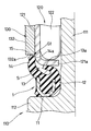
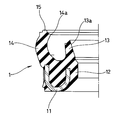
以下、本発明に係るユニバーサルジョイント用密封装置の好ましい実施の形態について、図面を参照しながら説明する。図1は、ユニバーサルジョイントを示す斜視図、図2は、本発明に係るユニバーサルジョイント用密封装置の第一の形態を示す装着状態の半断面図、図3は、図2のユニバーサルジョイント用密封装置を単独で示す半断面図である。
ユニバーサルジョイントは、図1に示されるように、駆動側回転軸及び従動側回転軸のそれぞれの軸端に設けられるヨーク130,130を、十字形スパイダ110を介して互いに角変位可能に連結したものである。十字形スパイダ110は、十字形をなすように互いに直角方向へ突出した四本の軸部(図2における参照符号111)と、その互いの交差部側から外径方向へ立ち上がるボス部112とを有し、各軸部111は、ヨーク130,130における二股状のアーム131,131の各端部に形成された連結環132,132にそれぞれベアリング120を介して嵌挿されている。
図2に示されるように、ベアリング120は、十字形スパイダ110の軸部111の外周に配置されると共に図1に示されるヨーク130における連結環132に嵌着される金属プレス成形品からなる有底円筒状の外輪121と、この外輪121と前記軸部111との間に介在された鋼製の多数の円柱状転動体122からなり、内部が不図示のグリースで潤滑されている。
本発明に係るユニバーサルジョイント用密封装置(以下、単に密封装置という)1は、図2及び図3に示されるように、鋼板等の金属板の打ち抜きプレス成形によって製作された金属環11と、この金属環11に一体成形(加硫接着)により設けられたゴム又はゴム状弾性を有する合成樹脂材料からなる固定シール部12、内側リップ13、外側リップ14及び突条部15とを備える。
密封装置1における固定シール部12は、請求項1に記載された固定部に相当するものであって、断面U字形をなす金属環11の内周側に形成され、十字形スパイダ110の軸部111の外周面に、適当なつぶし代をもって圧入嵌着されるものである。
密封装置1における内側リップ13は、図3に示されるように、先端側が大径となるような円錐筒状をなすものであって、その先端部の側面13aが、図2に示されるベアリング120の外輪121の端部に転動体122の抜け止めのために屈曲形成された内向きフランジ部121aの端面と適当な締め代をもって摺動可能に密接される。
密封装置1における外側リップ14は、図3に示されるように、内側リップ13の外周側を、突出方向の中腹部が外径側へ膨らんだ形状をなして、内側リップ13より長く延びるものであって、その先端部内周面14aが、図2に示されるベアリング120の外輪121の外周面と適当な締め代をもって摺動可能に密接される。
密封装置1における突条部15は、図3に示されるように、外側リップ14の先端部における厚さ方向中間部から軸方向へ突設されたものであって、図2に示されるベアリング120の外輪121が圧入されたヨーク130の連結環132の端面132aに、摺動可能に密接されている。なお、連結環132の端面132aは、請求項1に記載の「外輪の外周側に設けられた端面」に相当する。
以上のように構成された密封装置1は、ベアリング120の内部に封入されたグリースが外輪121の外部へ漏洩するのを防止すると共に、外部からの泥水や土埃等の侵入を防止するものである。
ここで、ベアリング120の作動時の発熱や雰囲気温度の変化によって内部のグリースが膨張あるいは収縮するので、これに伴ってベアリング120の内圧が変化する。しかしながら本発明の密封装置1によれば、外側リップ14の中腹部が外径側へ膨らんだ形状をなしているので、内側リップ13と外側リップ14の間に画成された空間Sは比較的大きな容積が確保されており、このためベアリング120の内圧変化を有効に緩和することができる。したがってベアリング120の内圧上昇によって内側リップ13の側面13aと外輪121の内向きフランジ部121aとの摺動部から外周側へ流出しようとするグリースは、空間S内に十分に保持される。そして、更に空間S自体の内圧上昇によって、この空間S内に保持されたグリースの一部が外側リップ14の先端部内周面14aとベアリング120の外輪121の外周面との摺動部から外周側へ流出しようとしても、このグリースは、連結環132の端面132aと摺動可能に密接された突条部15との間の密閉隙間G1に保持される。
したがって、ベアリング120の内圧上昇時にグリースが外部へ流出しにくく、また、グリースの一部が空間S及び隙間G1に保持されるので、内側リップ13、外側リップ14及び突条部15の摺動部が潤滑され、低トルク化が図られる。しかもグリースの流出が抑制される結果、ベアリング120の内圧が負圧になりにくく、したがって外部からの泥水等異物の侵入も有効に防止される。
次に図4は、本発明に係るユニバーサルジョイント用密封装置の第二の形態を示す装着状態の半断面図である。この形態では、密封装置1自体は先に説明した図3と同様のものであるが、装着状態において、突条部15が連結環132の端面132aと非接触で軸方向に近接対向された点で、図2と異なっている。
この構成によれば、連結環132の端面132aと突条部15との間にラビリンス状の隙間G2が形成される。したがって、空間Sの内圧上昇によって、この空間S内に保持されたグリースの一部が外側リップ14の先端部内周面14aとベアリング120の外輪121の外周面との摺動部から外周側へ流出しようとしても、このグリースは、前記ラビリンス状隙間G2に保持されることになる。このため、第一の形態と同様の効果が得られるのに加えて、突条部15が連結環132の端面132aと非接触であるため、一層の低トルク化が図られる。
1 密封装置
11 金属環
12 固定シール部(固定部)
13 内側リップ
14 外側リップ
15 突条部
110 十字形スパイダ
111 軸部
120 ベアリング
121 外輪
130 ヨーク
131 アーム
132 連結環
132a 端面
G1,G2 隙間
11 金属環
12 固定シール部(固定部)
13 内側リップ
14 外側リップ
15 突条部
110 十字形スパイダ
111 軸部
120 ベアリング
121 外輪
130 ヨーク
131 アーム
132 連結環
132a 端面
G1,G2 隙間
Claims (1)
- ユニバーサルジョイントにおける十字形スパイダの軸部の外周面に嵌着される固定部と、前記軸部を相対回転可能に支持するベアリングの外輪の端面に摺動可能に密接される内側リップと、前記内側リップの外周側に設けられた外側リップと、この外側リップの先端部に突設された突条部とを備え、前記外側リップの先端部の内周面が、前記外輪の外周面に摺動可能に密接され、前記突条部が、前記外輪の外周側に設けられた端面と密接又は軸方向に近接対向されたことを特徴とするユニバーサルジョイント用密封装置。
Applications Claiming Priority (2)
| Application Number | Priority Date | Filing Date | Title |
|---|---|---|---|
| JP2008213977A JP2010048354A (ja) | 2008-08-22 | 2008-08-22 | ユニバーサルジョイント用密封装置 |
| JP2008-213977 | 2008-08-22 |
Publications (1)
| Publication Number | Publication Date |
|---|---|
| WO2010021185A1 true WO2010021185A1 (ja) | 2010-02-25 |
Family
ID=41707065
Family Applications (1)
| Application Number | Title | Priority Date | Filing Date |
|---|---|---|---|
| PCT/JP2009/060484 Ceased WO2010021185A1 (ja) | 2008-08-22 | 2009-06-09 | ユニバーサルジョイント用密封装置 |
Country Status (2)
| Country | Link |
|---|---|
| JP (1) | JP2010048354A (ja) |
| WO (1) | WO2010021185A1 (ja) |
Cited By (1)
| Publication number | Priority date | Publication date | Assignee | Title |
|---|---|---|---|---|
| WO2014086613A1 (de) * | 2012-12-03 | 2014-06-12 | Gelenkwellenwerk Stadtilm GmbH | Zapfenkreuz für ein kreuzgelenk |
Families Citing this family (1)
| Publication number | Priority date | Publication date | Assignee | Title |
|---|---|---|---|---|
| JP2014214812A (ja) * | 2013-04-25 | 2014-11-17 | 株式会社ショーワ | 継手 |
Citations (3)
| Publication number | Priority date | Publication date | Assignee | Title |
|---|---|---|---|---|
| JPS5460151U (ja) * | 1977-10-03 | 1979-04-25 | ||
| JPS6059825U (ja) * | 1983-09-30 | 1985-04-25 | エヌオーケー株式会社 | ベアリングシ−ル |
| JPH0414819U (ja) * | 1990-05-29 | 1992-02-06 |
-
2008
- 2008-08-22 JP JP2008213977A patent/JP2010048354A/ja active Pending
-
2009
- 2009-06-09 WO PCT/JP2009/060484 patent/WO2010021185A1/ja not_active Ceased
Patent Citations (3)
| Publication number | Priority date | Publication date | Assignee | Title |
|---|---|---|---|---|
| JPS5460151U (ja) * | 1977-10-03 | 1979-04-25 | ||
| JPS6059825U (ja) * | 1983-09-30 | 1985-04-25 | エヌオーケー株式会社 | ベアリングシ−ル |
| JPH0414819U (ja) * | 1990-05-29 | 1992-02-06 |
Cited By (1)
| Publication number | Priority date | Publication date | Assignee | Title |
|---|---|---|---|---|
| WO2014086613A1 (de) * | 2012-12-03 | 2014-06-12 | Gelenkwellenwerk Stadtilm GmbH | Zapfenkreuz für ein kreuzgelenk |
Also Published As
| Publication number | Publication date |
|---|---|
| JP2010048354A (ja) | 2010-03-04 |
Similar Documents
| Publication | Publication Date | Title |
|---|---|---|
| JP5348365B2 (ja) | ユニバーサルジョイント用密封装置 | |
| WO2010113842A1 (ja) | 環状密封装置 | |
| JP6050080B2 (ja) | 密封型転がり軸受 | |
| JP6208665B2 (ja) | 密封装置 | |
| JP6439758B2 (ja) | 密封型スラスト玉軸受 | |
| WO2011001899A1 (ja) | 嵌合部の密封構造 | |
| JP2010025138A (ja) | 密封装置 | |
| WO2013176172A1 (ja) | 外輪回転用軸受 | |
| JP2013522551A (ja) | 改善されたシール要素接合部を有する低トルクシャフトシール | |
| KR101301075B1 (ko) | 휠 베어링용 실링 캡 | |
| CN210734273U (zh) | 转向中间轴防尘装置和电动汽车 | |
| JP2012500951A (ja) | クラッチレリーズ軸受 | |
| CN105465207B (zh) | 万向节 | |
| JP2017024522A (ja) | プロペラシャフト支持構造 | |
| WO2010021185A1 (ja) | ユニバーサルジョイント用密封装置 | |
| JP2017067166A (ja) | 密封装置及び密封装置付ハブユニット軸受 | |
| JP3191013U (ja) | オイルシール | |
| JP5348404B2 (ja) | ユニバーサルジョイント用密封装置 | |
| JP5196123B2 (ja) | ユニバーサルジョイント用密封装置 | |
| JP2013249875A (ja) | 摩擦伝動式波動変速機 | |
| JP3138507U (ja) | 密封装置 | |
| JP2005325924A (ja) | 密封装置 | |
| KR101404789B1 (ko) | 더스트캡을 갖는 베어링 | |
| KR100822573B1 (ko) | 자동차 등속 조인트용 부트 장치 | |
| KR20130137931A (ko) | 휠 베어링의 씰링 장치 |
Legal Events
| Date | Code | Title | Description |
|---|---|---|---|
| 121 | Ep: the epo has been informed by wipo that ep was designated in this application |
Ref document number: 09808121 Country of ref document: EP Kind code of ref document: A1 |
|
| NENP | Non-entry into the national phase |
Ref country code: DE |
|
| 122 | Ep: pct application non-entry in european phase |
Ref document number: 09808121 Country of ref document: EP Kind code of ref document: A1 |