WO2010021091A1 - Réfrigérateur - Google Patents
Réfrigérateur Download PDFInfo
- Publication number
- WO2010021091A1 WO2010021091A1 PCT/JP2009/003608 JP2009003608W WO2010021091A1 WO 2010021091 A1 WO2010021091 A1 WO 2010021091A1 JP 2009003608 W JP2009003608 W JP 2009003608W WO 2010021091 A1 WO2010021091 A1 WO 2010021091A1
- Authority
- WO
- WIPO (PCT)
- Prior art keywords
- container
- storage case
- refrigerator
- door
- storage chamber
- Prior art date
Links
Images


Classifications
-
- F—MECHANICAL ENGINEERING; LIGHTING; HEATING; WEAPONS; BLASTING
- F25—REFRIGERATION OR COOLING; COMBINED HEATING AND REFRIGERATION SYSTEMS; HEAT PUMP SYSTEMS; MANUFACTURE OR STORAGE OF ICE; LIQUEFACTION SOLIDIFICATION OF GASES
- F25D—REFRIGERATORS; COLD ROOMS; ICE-BOXES; COOLING OR FREEZING APPARATUS NOT OTHERWISE PROVIDED FOR
- F25D25/00—Charging, supporting, and discharging the articles to be cooled
- F25D25/02—Charging, supporting, and discharging the articles to be cooled by shelves
- F25D25/024—Slidable shelves
- F25D25/025—Drawers
-
- F—MECHANICAL ENGINEERING; LIGHTING; HEATING; WEAPONS; BLASTING
- F25—REFRIGERATION OR COOLING; COMBINED HEATING AND REFRIGERATION SYSTEMS; HEAT PUMP SYSTEMS; MANUFACTURE OR STORAGE OF ICE; LIQUEFACTION SOLIDIFICATION OF GASES
- F25D—REFRIGERATORS; COLD ROOMS; ICE-BOXES; COOLING OR FREEZING APPARATUS NOT OTHERWISE PROVIDED FOR
- F25D23/00—General constructional features
- F25D23/06—Walls
- F25D23/065—Details
- F25D23/067—Supporting elements
-
- F—MECHANICAL ENGINEERING; LIGHTING; HEATING; WEAPONS; BLASTING
- F25—REFRIGERATION OR COOLING; COMBINED HEATING AND REFRIGERATION SYSTEMS; HEAT PUMP SYSTEMS; MANUFACTURE OR STORAGE OF ICE; LIQUEFACTION SOLIDIFICATION OF GASES
- F25D—REFRIGERATORS; COLD ROOMS; ICE-BOXES; COOLING OR FREEZING APPARATUS NOT OTHERWISE PROVIDED FOR
- F25D2400/00—General features of, or devices for refrigerators, cold rooms, ice-boxes, or for cooling or freezing apparatus not covered by any other subclass
- F25D2400/22—Cleaning means for refrigerating devices
Definitions
- the present invention relates to a refrigerator, and particularly to a refrigerator provided with a drawer-type container.
- refrigerators are often provided with a pull-out type container from the viewpoint of being able to be stored without waste and easy to use. Since various foods and the like are stored in such a drawer-type container, an increase in the storage capacity of the container and ease of taking in and out the food and the like are required.
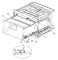
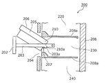
- FIG. 13 is a view showing the structure around the drawer-type container 206 in the conventional refrigerator 300. As shown in FIG.
- the conventional refrigerator 300 includes a box body 208.
- the space in the box 208 is partitioned by two partition walls 208a. Thereby, the storage room 220, the storage room 230, and the storage room 240 are formed in the box 208.
- the door 202 is provided in the opening part 204 of the front surface of the storage chamber 220, and the frame 203 is connected near the center part of the door 202 in the up-down direction.
- the container 206 accommodated in the storage chamber 220 has a flange portion 205.
- the frame 203 detachably supports the container 206 with a flange portion 205.
- the container 206 has an inclined portion 210 having an inclined surface 210a at the lower end of the rear end of the flange portion 205.
- the container 206 can be tilted to an angle at which the container 206 can be taken out of the refrigerator 300 without interference between the container 206 and the door 202.
- the user can remove the container 206 from the refrigerator 300 by tilting the container 206 in this way.
- the container 206 is provided using the space in the storage chamber 230 effectively.
- at least the space below the frame 203 is an invalid space that is not used for storing articles.
- the container 206 needs to be taken out while being inclined, and the container 206 needs to be attached to the frame 203 after being inserted into the storage chamber 230 while being inclined. Therefore, it cannot be said that the container 206 is easily attached and detached.
- the maximum pull-out distance of the container 206 is also restricted by the distance in which the rear portion of the container 206 remains in the storage chamber 230 by the locking projection 203a. For this reason, it is not easy to confirm the entire interior of the container 206, and it cannot be said that it is easy to put food in and out of the container 206.
- a refrigerator that is not a drawer type but has a hinged door with one opening, opens the hinged door, and pulls out the container from the opening of the storage room.
- Such a drawer-type container is required to be easy to put in and take out food and the like, and to be easily attached and detached, like the container that is pulled out integrally with the door.
- the technology for the conventional refrigerator 300 is a technology that enables the container that is pulled out integrally with the door to be attached and detached.
- the present invention has been made in consideration of the above-described conventional problems, and an object of the present invention is to provide a refrigerator including a user-friendly container that is a drawer-type container disposed inside a hinge-type door.
- a refrigerator includes a heat insulating box including an outer box, an inner box, a heat insulating material provided between the outer box and the inner box, and the heat insulation.
- a refrigerator comprising a storage chamber disposed inside the box and having an opening on the front surface, and a hinged door that closes the opening of the storage chamber so as to be openable and closable, and is disposed in the storage chamber.
- the rail member moves forward By sliding with the fixing member while being supported by the fixing member, the position of the rear end of the container in the front-rear direction is another component of the refrigerator than the front end of the component above the container. Also extends to the front position.
- the maximum pull-out distance of the container is a distance at which the position in the front-rear direction of the rear end of the container is a position ahead of the front ends of other components existing above the container.
- the container when the container is pulled out, it can be taken out of the refrigerator by lifting it vertically. That is, the container can be easily taken out from the refrigerator.
- the container when the container is attached to the refrigerator, the container can be attached to the refrigerator by lowering the container vertically from above the rail members with the left and right rail members extended. That is, the container can be easily attached to the refrigerator.
- the present invention can provide a refrigerator that is a drawer-type container disposed inside a hinged door and is easy to use.
- the drawer track means further comprises: another storage chamber disposed above the storage chamber and having an opening on the front surface; and another door for closing the opening of the other storage chamber so that the opening can be opened and closed.
- Another storage chamber disposed above the storage chamber and having an opening on the front surface
- another door for closing the opening of the other storage chamber so that the opening can be opened and closed.
- the position of the rear end of the container in the front-rear direction is a position ahead of the front of the upper storage chamber door.
- the container can be pulled out until Thereby, taking in and out of the food etc. with respect to the said container becomes easy, and attachment or detachment with respect to the refrigerator of the said container becomes easy.
- the other storage chamber disposed above the storage chamber and having an opening on the front surface, and the storage chamber and the other storage chamber are partitioned by vertically dividing an inner space of the heat insulating box.
- a partition for partitioning wherein the door is one door that closes an opening of the storage chamber so as to be openable and closable, and also closes an opening of the other storage chamber so as to be openable and closable. Is extended until the position in the front-rear direction of the rear end of the container is positioned in front of the front end of the partition which is the other end of the refrigerator and the front end of the upper component of the container. Also good.
- the container housed in the lower storage chamber has a position in the front-rear direction of the rear end of the container.
- the container can be pulled out to a position ahead of the front end of the partition.
- the rear end of the container is located up to a position ahead of the front end surface of the partition, so that the container is lifted vertically upward, or Even if it does not reach the place where it is lowered and attached, it can be attached and detached relatively easily while the container is slightly inclined.
- the storage space is located above the container.
- the container When the container is pulled out by opening the door of the storage chamber, the container has a rear end located at a position ahead of the front end surface of the partition, and the container can be opened by opening the door of the storage chamber. Can be attached or detached by lifting the plate vertically upward or down.
- a refrigerator in order to solve the above-described conventional problems, includes an outer box, an inner box, a heat insulating box body including a heat insulating material provided between the outer box and the inner box, A refrigerator comprising a storage chamber disposed inside the heat insulation box and having an opening on a front surface, and a hinged door that closes the opening of the storage chamber so as to be openable and closable, and is disposed in the storage chamber A first container for storing articles; and a drawer track means for supporting the first container so as to be attachable and detachable in the vertical direction, and for extending and retracting to support the first container.
- the track means is elongate in the front-rear direction, a rail member that is detachably attached to each of both ends in the left-right direction at the lower part of the first container, and supports the rail member slidably in the front-rear direction And a fixing member fixed in the storage chamber.
- each of the left and right rail members is attached to the lower part and the left and right ends of the first container.
- the present invention can provide a refrigerator that is a drawer-type container disposed inside a hinged door and is easy to use.
- the first container has attachment holes disposed at both ends in the left and right direction at the lower part of the first container, and the rail member has a protrusion that protrudes upward and engages with the attachment hole.
- the drawer track means supports the first container so as to be detachable in the vertical direction by allowing the protrusions of the left and right rail members to be inserted into and removed from the left and right mounting holes of the first container. You may do that.
- the first container is firmly held by the drawing track means by inserting the protruding portion of the rail member into the mounting hole of the first container.
- the user can easily remove the first container from the drawing track means by lifting the first container upward.
- the first container may be formed of a light-transmitting resin that can visually recognize the stored contents in the first container from the side of the first container. According to this structure, the visibility with respect to the inside of the first container is improved. Further, since the rail member is attached to the lower portion of the first container, the visibility of the inside of the first container from the side is particularly good. Thereby, the user can confirm easily the kind and number, etc. of the foodstuffs accommodated in the 1st container, for example.
- a second container that is shallower than the first container and that supports the left end and the right end of the first container on the left end and the right end of the upper part of the first container may be provided.
- the user can selectively use the first container and the second container.
- the second container suppresses the distortion amount of the first container when a heavy food is stored in the first container.
- the present invention can provide a refrigerator including a user-friendly container that is a drawer-type container disposed inside a hinge-type door.
- FIG. 1 is a front view of the refrigerator according to Embodiment 1 of the present invention.
- FIG. 2 is a longitudinal sectional view of the refrigerator according to the first embodiment.
- FIG. 3 is an enlarged perspective view showing the appearance of the storage case in the first embodiment.
- FIG. 4 is a plan sectional view showing the storage case and the drawer unit according to the first embodiment.
- FIG. 5 is a schematic diagram showing the maximum pull-out distance of the storage case in the first embodiment.
- FIG. 6 is a front view of the refrigerator according to the second embodiment of the present invention.
- FIG. 7 is a schematic diagram showing the maximum pull-out distance of the storage case in the second embodiment.
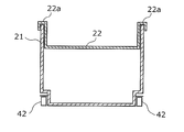
- FIG. 8A is a view showing a longitudinal section of the storage case in the third embodiment.
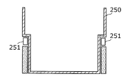
- FIG. 8B is a view showing a longitudinal section of a conventional general pull-out type container.
- FIG. 9 is a diagram showing a mounting hole of the storage case and a protruding portion of the rail member in the third embodiment.
- FIG. 10A is a schematic cross-sectional view illustrating a manner in which the accessory case is attached to the storage case in the third embodiment.
- FIG. 10B is a first diagram illustrating another example of how the accessory case is attached to the storage case in the third embodiment.
- FIG. 10C is a second diagram illustrating another example of the attachment of the accessory case to the storage case in the third embodiment.
- FIG. 11 is a schematic diagram showing the maximum pull-out distance of the storage case in the third embodiment.
- FIG. 12 is a schematic diagram showing the maximum pull-out distance of the storage case in the fourth embodiment.
- FIG. 13 is a view showing a structure around a drawer-type container in a conventional refrigerator.
- FIG. 1 is a front view of a refrigerator 100 according to Embodiment 1 of the present invention.
- the refrigerator 100 is a refrigerator including two doors, and includes a storage room partitioned into three in a heat insulating box 70.
- the heat insulation box 70 is constituted by a heat insulation wall in which a foam heat insulation 73 is filled in a space constituted by an inner box 71 obtained by vacuum molding a resin body such as ABS and an outer box 72 using a metal material such as a pre-coated steel plate. Has been.
- the refrigerator 100 includes a refrigerator compartment 10, a vegetable compartment 20, and a freezer compartment 30.
- rectangular dotted lines represent the openings of the respective storage chambers.
- the vegetable compartment 20 accommodates a drawer-type container described later.
- a heat insulating door filled with a foam heat insulating material such as urethane is provided.
- a hinge-type first door 11 is provided that closes the opening of the refrigerator compartment 10 and the vegetable compartment 20 so as to be freely opened and closed.
- the first door 11 is provided with a hinge at the left end, and rotates around a vertical rotation axis.
- the first door 11 is an example of a hinged door in the refrigerator of the present invention.
- the freezer compartment 30 is provided with a drawer-type second door 31.
- the refrigerator compartment 10 is cooled by a direct cooling method, and the vegetable compartment 20 and the freezer compartment 30 are cooled by an indirect cooling method.
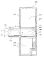
- FIG. 2 is a longitudinal sectional view of the refrigerator 100 according to the first embodiment.
- the refrigerator compartment 10 and the vegetable compartment 20 are partitioned by the upper partition 15 in the heat insulating box 70.
- the vegetable compartment 20 and the freezer compartment 30 are partitioned by a lower partition 25.
- the refrigerator 100 includes two coolers. Specifically, the first cooler 12 is provided on the back side of the back surface 10 a of the refrigerator compartment 10. The back surface 10 a of the refrigerator compartment 10 is cooled by heat conduction from the first cooler 12. The air in the refrigerator compartment 10 is cooled by the cooled back surface 10a.
- the first cooler 12 has a cooling pipe 12a and a metal plate 12b.
- the back surface 10a of the refrigerator compartment 10 is directly cooled by the metal plate 12b attached so as to contact the back side of the back surface 10a.
- the refrigerator 100 includes a second cooler 32 on the back side of the back surface of the freezer compartment 30.
- the inside of the freezer compartment 30 is cooled by circulating the cool air discharged from the second cooler 32.
- the cold air discharged from the second cooler 32 is also supplied to the vegetable compartment 20 and is maintained in a temperature zone between, for example, the temperature zone of the refrigerator compartment 10 and the temperature zone of the freezer compartment 30 by opening / closing control of the damper.
- the vegetable compartment 20 accommodates a drawer-type storage case 21, and the user can pull out the storage case 21 by opening the first door 11.
- the storage case 21 is an example of a container in the refrigerator of the present invention.
- the refrigerator 100 according to the first embodiment is characterized in that food and the like can be easily taken in and out of the storage case 21 and the storage case 21 can be easily attached and detached.
- the storage case 21 and its drawer configuration will be described with reference to FIGS.
- FIG. 3 is an enlarged perspective view showing an appearance of the storage case 21 in the first embodiment.
- the storage case 21 is supported by a rail member 42.
- the rail member 42 is long in the front-rear direction, and is supported by a fixing member 41 fixed in the vegetable compartment 20 so as to be slidable in the front-rear direction.
- the storage case 21 has holding portions 23 that protrude to the outside of the warehouse at both ends in the left-right direction, more specifically, at the bottom of the storage case 21 and at both ends in the left-right direction.
- the holding portion 23 is provided with an attachment hole 23a for detachably attaching the storage case 21 to the rail member 42.
- the rail member 42 is provided with a protruding portion 43 that protrudes upward and engages with the mounting hole 23a.
- Each of the protrusions 43 of the left and right rail members 42 of the storage case 21 can be inserted into and removed from the mounting hole 23a.
- the drawer unit 40 supports the storage case 21 so as to be detachable in the vertical direction.
- the storage case 21 is formed of a light-transmitting resin capable of confirming the storage items in the storage case 21 from the side of the storage case 21. That is, the storage case 21 is made of a resin having a relatively high transparency.
- the type and number of food items stored in the storage case 21 can be easily confirmed from the side of the storage case 21.
- an accessory case 22 shallower than the storage case 21 is detachably attached to the upper part and the rear part of the storage case 21.
- the storage case 21 and the accessory case 22 can be properly used.
- the small case 22 suppresses the amount of distortion of the storage case 21 when a heavy food is stored in the storage case 21.
- the drawer unit 40 is an example of a drawer track means in the refrigerator of the present invention, and is constituted by the left and right rail members 42 and the fixing member 41 of the storage case 21.
- FIG. 4 is a plan sectional view showing the storage case 21 and the drawer unit 40 in the first embodiment.
- the drawer unit 40 includes a fixing member 41 and a rail member 42 arranged on the left and right sides of the storage case 21.
- each of the two rail members 42 includes a middle rail 42a and a support rail 42b.
- the support rail 42b is a rail that directly supports the storage case 21, and is slidable in the front-rear direction with respect to the middle rail 42a. Further, the middle rail 42 a can slide in the front-rear direction with respect to the fixing member 41.
- the entire drawing unit 40 can be expanded and contracted in the front-rear direction.
- the storage case 21 is pulled by the user when the first door 11 rotates as shown in FIG. 4 about the rotation shaft 50 of the hinge, that is, when the first door 11 is opened.
- the drawer unit 40 is extended, and the storage case 21 is pulled out from the vegetable compartment 20.
- the maximum pull-out distance of the storage case 21 is a distance that improves the usability of the storage case 21.
- FIG. 5 is a schematic diagram showing the maximum pull-out distance of the storage case 21 in the first embodiment.
- the position of the rear end A of the storage case 21 in the front-rear direction is more forward than the front end B of the upper partition 15 above the storage case 21. Stretch until positioned.
- the upper partition 15 in this Embodiment 1 is an example of the structure part above the container in the refrigerator of this invention.
- the user can easily confirm what is stored in the storage case 21. Further, when food is stored in the storage case 21, it can be easily stored at any position in the storage case 21.
- the user when taking out food or the like from the storage case 21, the user can easily take out the food at any position in the storage case 21.
- the user can take out the storage case 21 from the refrigerator 100 only by lifting the storage case 21 vertically without performing an operation for avoiding the upper partition 15 such as tilting the storage case 21.
- the user can attach the storage case 21 to the drawer unit 40 only by lowering the storage case 21 from above the rail member 42 while the drawer unit 40 is extended as shown in FIG. it can.
- the refrigerator 100 includes the drawer-type storage case 21 accommodated in the vegetable compartment 20.
- the maximum pull-out distance is a distance at which the position of the rear end A of the storage case 21 in the front-rear direction is positioned forward of the front end B of the upper partition 15 above the storage case 21.
- the user can easily check the stored items in the storage case 21 and put in and out foods from the storage case 21.
- the fact that the storage case 21 is easily attached and detached also means that the ease of cleaning of the storage case 21 is improved, which is very useful for keeping the storage case 21 in which food is stored clean. is there.
- the refrigerator 100 is a refrigerator 100 that is a drawer-type storage case 21 arranged on the inner side of the hinge-type first door 11 and includes an easy-to-use storage case 21.
- FIG. 6 is a front view of the refrigerator 200 according to the second embodiment of the present invention.
- the refrigerator 200 is a refrigerator including three doors, and includes three storage chambers in the heat insulating box 170.
- the refrigerator 200 includes a refrigerator compartment 110, a vegetable compartment 120 whose room temperature can be changed, and a freezer compartment 130.
- a heat insulating door is provided at the opening of each storage room.
- the refrigerator 200 opens and closes the upper door 111 that opens and closes the opening of the refrigerator compartment 110, the middle door 121 that closes the opening of the vegetable compartment 120, and the opening of the freezer compartment 130. And a lower door 131 that is freely closed.
- rectangular dotted lines represent the openings of the respective storage rooms.
- the upper door 111 and the middle door 121 are hinge type doors, each provided with a hinge at the left end, and rotated around a vertical rotation axis.
- the middle door 121 is another example of a hinged door in the refrigerator of the present invention.
- the upper door 111 is an example of the other door in the refrigerator of this invention.
- the cooling method for each of the three storage rooms is the same as that in the first embodiment. That is, the refrigerator compartment 110 is cooled by a direct cooling method, and the vegetable compartment 120 and the freezer compartment 130 are cooled by an indirect cooling method.
- a drawer-type storage case 21 is stored, and is detachably supported by a drawer unit 140 described later.
- the refrigerator 200 of the second embodiment is provided with a door in each of the refrigerator compartment 110 and the vegetable compartment 120.
- the maximum pull-out distance of the storage case 21 in the second embodiment is different from the maximum pull-out distance of the storage case 21 in the first embodiment.
- FIG. 7 is a schematic diagram showing the maximum pull-out distance of the storage case 21 in the second embodiment.
- the storage case 21 is arranged in a vegetable compartment 120 whose upper and lower sides are partitioned by an upper partition 115 and a lower partition 125, and is supported by the drawer unit 140.
- the basic configuration of the drawer unit 140 is the same as that of the drawer unit 40 of the first embodiment, and the fixing member 141 and the rail member 142 arranged on the left and right sides (the back side and the near side in FIG. 7) of the storage case 21, respectively. And have.
- the rail member 142 is composed of two rails that slide on each other.
- the rail member 142 is provided with a protruding portion 143 and engages with the mounting hole 23a of the storage case 21 so as to be able to be put in and out. That is, the storage case 21 is detachably supported by the rail member 142 in the vertical direction.
- the drawer unit 140 has the same basic configuration as the drawer unit 40 of the first embodiment. However, the drawer unit 140 is configured such that the maximum drawer distance of the storage case 21 is longer than the maximum drawer distance by the drawer unit 40 of the first embodiment.
- the drawer unit 140 is positioned until the position of the rear end A of the storage case 21 in the front-rear direction (left-right direction in FIG. 7) is more forward than the front surface C of the upper door 111 above the storage case 21. Elongate.
- the user can easily check the contents of the storage case 21 and easily put food in and out of the storage case 21.
- a relatively large food can be taken in and out of the storage case 21.
- the storage case 21 when the storage case 21 is pulled out to the maximum pull-out distance and is removed from the rail member 142 by lifting the storage case 21, the storage case 21 does not interfere with the upper door 111 that is another component.
- the user can remove the storage case 21 from the rail member 142 only by lifting the storage case 21 upward without performing an operation for avoiding the upper door 111.
- the user can attach the storage case 21 to the rail member 142 only by the operation of lowering the storage case 21 toward the rail member 42.
- the refrigerator 200 according to the second embodiment is a refrigerator 200 that is a drawer-type storage case 21 disposed inside the hinged inner door 121 and includes the user-friendly storage case 21.
- the drawer unit 140 may extend until the position in the front-rear direction of the rear end A of the storage case 21 is located between the front end of the upper partition 115 and the front surface C of the upper door 111.
- the upper door 111 may not be a substantial obstacle that hinders the usability of the storage case 21.
- the storage case 21 can be taken out of the refrigerator 200 without causing the rear end of the storage case 21 to interfere with the upper door 111.
- the operation necessary for taking out the storage case 21 is not only the operation of lifting the storage case 21 vertically.
- the operation for avoiding the upper door 111 required when taking out the storage case 21 is very small.
- the presence of the upper door 111 does not become an obstacle that significantly reduces the confirmation of the contents and the ease of taking in and out the food.
- the drawer unit 140 is extended until the position in the front-rear direction of the rear end A of the storage case 21 is located between the front end of the upper partition 115 and the front surface C of the upper door 111.
- the convenience of the storage case 21 is better than that of a conventional drawer-type container.
- the rear end of the container is located up to a position ahead of the front end surface of the partition, so that the container is lifted vertically upward, or Even if it does not reach the place where it is lowered and attached, it can be attached and detached relatively easily while the container is slightly inclined.
- the storage space is located above the container.
- the rear end of the container is positioned to a position ahead of the front end surface of the partition.
- the container can be attached or detached by lifting it vertically upward or lowering it.
- the direct cooling method and the indirect cooling method are adopted as the cooling methods for the three storage rooms.
- the cooling method of each storage room is not limited to a specific one.
- all of the refrigerator compartment 10, the vegetable compartment 20, and the freezer compartment 30 may be cooled by an indirect cooling method.
- each storage room is not limited to the type described in the first and second embodiments.
- the vegetable room 20 and the vegetable room 120 may be a storage room called a variable temperature room in which a user can set a temperature zone.
- the hinge type doors such as the first door 11 and the middle door 121 are so-called single-open doors.
- the hinged doors such as the first door 11 and the middle door 121 are double doors in which each of the two door plates arranged on the left and right pivots around a pivot axis near the outer edge. There may be.
- one first door 11 may be constituted by two door plates. The same applies to the middle door 121.
- the effect of improving the usability of the storage case 21, which is the effect of the present invention is exhibited without depending on the type of storage room, the cooling method, and the like.
- FIGS. A front view, a longitudinal sectional view, an enlarged perspective view showing the appearance of the storage case, and a plan sectional view showing the storage case and the drawer unit of the refrigerator 100 according to the third embodiment of the present invention are shown in FIGS. Since it is the same as the front view of the refrigerator 100 of Embodiment 1, the longitudinal cross-sectional view, the expansion perspective view which shows the external appearance of a storage case, and the plane sectional view which shows a storage case and a drawer unit, description is abbreviate
- the storage case 21 shown in FIG. 2 is an example of a first container in the refrigerator of the present invention.
- the accessory case 22 is an example of a second container in the refrigerator of the present invention. The manner in which the accessory case 22 is attached to the storage case 21 will be described later with reference to FIG. 10A.
- the storage case 21 is provided by effectively using the space in the vegetable compartment 20.
- FIG. 8A is a diagram showing a longitudinal section of the storage case 21 according to the third embodiment
- FIG. 8B is a diagram showing a longitudinal section of a conventional general drawer-type container 250.
- the left and right rail members 251 are generally attached to the center in the vertical direction at both ends of the container 250.
- the left and right rail members 42 are attached to the lower portion and the end portion of the storage case 21.
- the storage case 21 according to the third embodiment is provided in the refrigerator 100 by effectively using an invalid space existing outside the conventional container 250.
- the storage capacity is larger when the storage case 21 is provided.
- the storage case 21 is formed of a highly transparent resin, and the rail member 42 is disposed at the lower part of the storage case 21. Therefore, the visibility inside the storage case 21 when the storage case 21 is viewed from the side is very good.
- the user can easily check the type and number of food items stored in the storage case 21 from the side of the storage case 21.
- the storage case 21 is securely attached to the rail member 42, so that it is firmly held by the drawer unit 40 and can be easily detached from the rail member 42.
- FIG. 9 is a diagram showing the mounting hole 23a of the storage case 21 and the protrusion 43 of the rail member 42 in the third embodiment.
- the rail member 42 has a protrusion 43 near the tip of the support rail 42b.
- the protrusion part 43 has an elastic member which the upper end part and the lower end part inclined before and after (left and right in FIG. 9).
- the width in the front-rear direction of the protruding portion 43 is larger than the width of the mounting hole 23 a arranged in the holding portion 23 of the storage case 21.
- the protrusion 43 is inserted into the attachment hole 23a while reducing the width.
- the storage case 21 is firmly held by the drawer unit 40 by the protrusion 43 being inserted into the mounting hole 23a of the storage case 21.
- the protruding portion 43 is extracted from the mounting hole 23a while reducing the width.
- the storage case 21 can be easily detached from the rail member 42 by lifting the storage case 21 upward with respect to the rail member 42.
- the accessory case 22 is detachably attached to the storage case 21.
- the amount of distortion of the storage case 21 is suppressed.
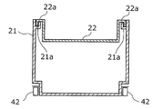
- FIG. 10A is a schematic cross-sectional view showing an aspect of attachment of the accessory case 22 to the storage case 21 in the third embodiment.
- the accessory case 22 is provided with locking portions 22a having return portions downward at both ends.
- the accessory case 22 is attached to the storage case 21 so that these locking portions 22 a are hung on the upper ends of the left and right side walls of the storage case 21.
- the user can use the storage case 21 and the accessory case 22 properly.
- the amount of inclination of the side wall of the storage case 21 when the heavy food is stored in the storage case 21 is suppressed. That is, the distortion amount of the storage case 21 is suppressed by the accessory case 22.
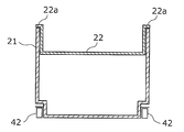
- FIG. 1 Another aspect may be sufficient as the aspect of attachment with respect to the storage case 21 of the accessory case 22.
- a mounting portion 21a having a groove may be provided on the inner upper ends of the left and right side walls of the storage case 21.
- the accessory case 22 is attached to the storage case 21 by inserting the engaging portions 22a at both ends of the accessory case 22 into the grooves of the left and right attachment portions 21a.
- the accessory case 22 may be attached to the storage case 21 so that a locking portion 22 a having no downward return portion is placed on the upper ends of the left and right side walls of the storage case 21. .
- the accessory case 22 is attached to the storage case 21 so that the left end and the right end of the storage case 21 are supported by the left end and the right end of the upper portion of the storage case 21. The amount of distortion is suppressed.
- the maximum pull-out distance of the storage case 21 is a distance that improves the usability of the storage case 21.
- FIG. 11 is a schematic diagram showing the maximum pull-out distance of the storage case 21 in the third embodiment.
- the position of the rear end A of the storage case 21 in the front-rear direction is more forward than the front end B of the upper partition 15 above the storage case 21. Stretch until positioned.
- the user can easily confirm what is stored in the storage case 21. Further, when food is stored in the storage case 21, it can be easily stored at any position in the storage case 21.
- the user when taking out food or the like from the storage case 21, the user can easily take out the food at any position in the storage case 21.
- the user can take out the storage case 21 from the refrigerator 100 only by lifting the storage case 21 vertically without performing an operation for avoiding the upper partition 15 such as tilting the storage case 21.
- the user can attach the storage case 21 to the drawer unit 40 only by lowering the storage case 21 from above the rail member 42 with the drawer unit 40 extended as shown in FIG. it can.
- the refrigerator 100 includes the drawer-type storage case 21 accommodated in the vegetable compartment 20.
- each of the left and right rail members 42 that support the storage case 21 is attached to the lower portion and the end of the storage case 21.
- the stability when the storage case 21 is pulled out and pushed back is ensured, and the invalid space existing outside the storage case 21 can be minimized. That is, the capacity of the storage case 21 can be increased as compared with the conventional case.
- the storage case 21 is formed of a highly transparent resin and the rail member 42 is disposed at the lower part of the storage case 21, the internal visibility from the side of the storage case 21 is very good.
- the storage case 21 is attached to the rail member 42 by the protrusion 43 of the rail member 42 being inserted into the attachment hole 23 a at the lower part of the storage case 21. Thereby, the storage case 21 is firmly held by the drawer unit 40. Further, the storage case 21 can be easily detached from the drawer unit 40.
- the accessory case 22 is attached to the storage case 21, the amount of distortion of the storage case 21 is suppressed.
- the maximum pull-out distance of the storage case 21 is a distance at which the position of the rear end A of the storage case 21 in the front-rear direction is positioned forward of the front end B of the upper partition 15 above the storage case 21.
- the user can easily check the stored items in the storage case 21 and put in and out foods from the storage case 21.
- the fact that the storage case 21 is easily attached and detached also means that the ease of cleaning of the storage case 21 is improved, which is very useful for keeping the storage case 21 in which food is stored clean. is there.
- the refrigerator 100 is a drawer 100 that is a drawer-type storage case 21 disposed inside the hinge-type first door 11 and has a convenient storage case 21.
- Embodiment 4 As a fourth embodiment, a refrigerator including three doors will be described.
- the front view of the refrigerator 200 of this Embodiment 4 is the same as that of the refrigerator 200 of Embodiment 2 shown by FIG. 6, description is abbreviate
- FIG. 12 is a schematic diagram showing the maximum pull-out distance of the storage case 21 in the fourth embodiment.
- the storage case 21 is arranged in a vegetable compartment 120 whose upper and lower sides are partitioned by an upper partition 115 and a lower partition 125, and is supported by the drawer unit 140.
- the basic configuration of the drawer unit 140 is the same as that of the drawer unit 40 of the third embodiment.
- the fixing member 141 and the rail member 142 are arranged on the left and right sides (the back side and the near side in FIG. 12) of the storage case 21, respectively. And have.
- the rail member 142 is composed of two rails that slide on each other.
- the rail member 142 is provided with a protrusion 143.
- the storage case 21 is attached to the rail member 142 by inserting the protruding portion 143 into the attachment hole 23 a in the lower part of the storage case 21.
- each of the left and right rail members 142 is attached to the lower portion and the end portion of the storage case 21.
- the stability when the storage case 21 is pulled out and pushed back is ensured, and the invalid space existing outside the storage case 21 can be minimized. Moreover, the internal visibility from the side of the storage case 21 is very good.
- the storage case 21 is firmly held by the drawer unit 140 by inserting the protruding portion 143 into the mounting hole 23a at the bottom of the storage case 21. Further, the storage case 21 can be easily detached from the drawer unit 140.
- the drawer unit 140 has the same basic configuration as the drawer unit 40 of the third embodiment. However, the drawer unit 140 is configured such that the maximum pull-out distance of the storage case 21 is longer than the maximum pull-out distance by the pull-out unit 40 of the third embodiment.
- the position of the rear end A of the storage case 21 in the front-rear direction (left-right direction in FIG. 12) is positioned forward of the front surface C of the upper door 111 above the storage case 21. Elongate.
- the user can easily check the contents of the storage case 21 and easily put food in and out of the storage case 21.
- a relatively large food can be taken in and out of the storage case 21.
- the storage case 21 when the storage case 21 is pulled out to the maximum pull-out distance and is removed from the rail member 142 by lifting the storage case 21, the storage case 21 does not interfere with the upper door 111 that is another component.
- the user can remove the storage case 21 from the rail member 142 only by lifting the storage case 21 upward without performing an operation for avoiding the upper door 111.
- the user can attach the storage case 21 to the rail member 142 only by the operation of lowering the storage case 21 toward the rail member 42.
- the refrigerator 200 according to the fourth embodiment is a drawer 200 that is a drawer-type storage case 21 that is arranged inside the hinged inner door 121 and is provided with an easy-to-use storage case 21.
- the drawer unit 140 may extend until the position in the front-rear direction of the rear end A of the storage case 21 is located between the front end of the upper partition 115 and the front surface C of the upper door 111.
- the upper door 111 may not be a substantial obstacle that hinders the usability of the storage case 21.
- the storage case 21 can be taken out of the refrigerator 200 without causing the rear end of the storage case 21 to interfere with the upper door 111.
- the operation necessary for taking out the storage case 21 is not only the operation of lifting the storage case 21 vertically.
- the operation for avoiding the upper door 111 required when taking out the storage case 21 is very small.
- the presence of the upper door 111 does not become an obstacle that significantly reduces the confirmation of the contents and the ease of taking in and out the food.
- the drawer unit 140 is extended until the position in the front-rear direction of the rear end A of the storage case 21 is located between the front end of the upper partition 115 and the front surface C of the upper door 111.
- the convenience of the storage case 21 is better than the conventional drawer-type container.
- the direct cooling method and the indirect cooling method are adopted as the cooling methods for the three storage rooms.
- the cooling method of each storage room is not limited to a specific one.
- all of the refrigerator compartment 10, the vegetable compartment 20, and the freezer compartment 30 may be cooled by an indirect cooling method.
- each storage room is not limited to the type described in the third and fourth embodiments.
- the vegetable room 20 and the vegetable room 120 may be a storage room called a variable temperature room in which a user can set a temperature zone.
- the hinge type doors such as the first door 11 and the middle door 121 are so-called single-open doors.
- the hinged doors such as the first door 11 and the middle door 121 are double doors in which each of the two door plates arranged on the left and right pivots around a pivot axis near the outer edge. There may be.
- one first door 11 may be constituted by two door plates. The same applies to the middle door 121.
- the effect of improving the usability of the storage case 21, which is the effect of the present invention is exhibited without depending on the type of storage room, the cooling method, and the like.
- the present invention can provide a refrigerator including a user-friendly container that is a drawer-type container disposed inside a hinge-type door. Therefore, the present invention is useful as refrigerators of various types and sizes such as home use and business use.
Landscapes
- Engineering & Computer Science (AREA)
- Chemical & Material Sciences (AREA)
- Combustion & Propulsion (AREA)
- Physics & Mathematics (AREA)
- Mechanical Engineering (AREA)
- Thermal Sciences (AREA)
- General Engineering & Computer Science (AREA)
- Refrigerator Housings (AREA)
Abstract
L'invention porte sur un réfrigérateur équipé d'un bac de type coulissant, facile à utiliser, qui est disposé à l'intérieur du réfrigérateur et qui possède une porte à charnière. Le réfrigérateur (100) est équipé d'un compartiment isotherme (70), d'un compartiment à légumes (20) qui est disposé à l'intérieur du compartiment isotherme (70) et qui possède une partie ouverte sur sa surface avant, et d'une première porte à charnière (11) qui obstrue la partie ouverte du compartiment à légumes (20) et qui peut être librement ouverte et fermée. De plus, le réfrigérateur est équipé d'une boîte de stockage (21) qui est disposée à l'intérieur du compartiment à légumes (20) et qui stocke des produits, et d'une unité coulissante (40) qui porte la boîte de stockage (21) de telle sorte qu'elle peut être sortie. L'unité coulissante (40) possède un élément de rail (42) et un élément stationnaire (41) et, par l'intermédiaire de l'élément de rail (42) qui glisse vers l’avant avec l'élément stationnaire (41) tout en étant portée par l'élément stationnaire (41), la position de l'extrémité arrière (A) de la boîte de stockage (21) dans la direction longitudinale est étendue vers une position plus avant que l'extrémité avant (B) d'un composant structurel qui est au-dessus de la boîte de stockage (21) et qui est un autre composant structurel du réfrigérateur.
Priority Applications (2)
| Application Number | Priority Date | Filing Date | Title |
|---|---|---|---|
| CN2009801324202A CN102124289B (zh) | 2008-08-19 | 2009-07-30 | 冷藏库 |
| EP09808027.8A EP2320180A4 (fr) | 2008-08-19 | 2009-07-30 | Réfrigérateur |
Applications Claiming Priority (4)
| Application Number | Priority Date | Filing Date | Title |
|---|---|---|---|
| JP2008210429A JP2011214725A (ja) | 2008-08-19 | 2008-08-19 | 冷蔵庫 |
| JP2008-210428 | 2008-08-19 | ||
| JP2008210428A JP2011214724A (ja) | 2008-08-19 | 2008-08-19 | 冷蔵庫 |
| JP2008-210429 | 2008-08-19 |
Publications (1)
| Publication Number | Publication Date |
|---|---|
| WO2010021091A1 true WO2010021091A1 (fr) | 2010-02-25 |
Family
ID=41706984
Family Applications (1)
| Application Number | Title | Priority Date | Filing Date |
|---|---|---|---|
| PCT/JP2009/003608 WO2010021091A1 (fr) | 2008-08-19 | 2009-07-30 | Réfrigérateur |
Country Status (3)
| Country | Link |
|---|---|
| EP (1) | EP2320180A4 (fr) |
| CN (1) | CN102124289B (fr) |
| WO (1) | WO2010021091A1 (fr) |
Cited By (7)
| Publication number | Priority date | Publication date | Assignee | Title |
|---|---|---|---|---|
| US20120306338A1 (en) * | 2010-03-25 | 2012-12-06 | Panasonic Corporation | Refrigerator |
| JP2013064567A (ja) * | 2011-09-20 | 2013-04-11 | Panasonic Corp | 冷蔵庫 |
| JP2013064527A (ja) * | 2011-09-16 | 2013-04-11 | Panasonic Corp | 冷蔵庫 |
| JP2013253752A (ja) * | 2012-06-08 | 2013-12-19 | Hitachi Appliances Inc | 冷蔵庫 |
| US20190293340A1 (en) * | 2018-03-26 | 2019-09-26 | Lg Electronics Inc. | Refrigerator |
| US10598426B2 (en) * | 2018-03-16 | 2020-03-24 | Lg Electronics Inc. | Refrigerator |
| CN113491400A (zh) * | 2020-04-03 | 2021-10-12 | 合肥华凌股份有限公司 | 隔板组件及储物柜 |
Families Citing this family (6)
| Publication number | Priority date | Publication date | Assignee | Title |
|---|---|---|---|---|
| CN102954657B (zh) * | 2011-08-27 | 2017-05-17 | 博西华家用电器有限公司 | 家用电器 |
| CN103765138B (zh) * | 2011-08-31 | 2016-07-06 | 松下电器产业株式会社 | 冰箱 |
| JP5783983B2 (ja) * | 2012-09-26 | 2015-09-24 | 日立アプライアンス株式会社 | 冷蔵庫 |
| KR101860713B1 (ko) * | 2013-02-23 | 2018-05-24 | 삼성전자주식회사 | 슬라이딩 장치 및 이를 갖는 냉장고 |
| WO2015021589A1 (fr) * | 2013-08-13 | 2015-02-19 | 海信容声(广东)冰箱有限公司 | Réfrigérateur pourvu d'une zone de température variable individuellement |
| CN116105425B (zh) * | 2023-04-11 | 2023-06-23 | 合肥市超港食品有限公司 | 一种食品加工用冷藏装置 |
Citations (4)
| Publication number | Priority date | Publication date | Assignee | Title |
|---|---|---|---|---|
| JPS626694U (fr) | 1985-06-26 | 1987-01-16 | ||
| JP2000039256A (ja) * | 1998-07-27 | 2000-02-08 | Fujitsu General Ltd | 冷蔵庫 |
| JP2005300035A (ja) * | 2004-04-13 | 2005-10-27 | Matsushita Electric Ind Co Ltd | 冷蔵庫 |
| JP2008039295A (ja) * | 2006-08-07 | 2008-02-21 | Toshiba Corp | 冷凍冷蔵庫 |
Family Cites Families (4)
| Publication number | Priority date | Publication date | Assignee | Title |
|---|---|---|---|---|
| DE9314893U1 (de) * | 1993-10-01 | 1994-02-10 | Grass Ag | Schubladenführung mit Verbindungseinrichtung zwischen Schublade und Führungsschiene |
| CA2453680A1 (fr) * | 2003-12-18 | 2005-06-18 | Camco Inc. | Bac a legumes ou a fruits de refrigerateur |
| JP4434133B2 (ja) * | 2004-11-26 | 2010-03-17 | パナソニック株式会社 | 冷蔵庫 |
| DE102007006611A1 (de) * | 2007-02-06 | 2008-08-07 | BSH Bosch und Siemens Hausgeräte GmbH | Kältegerät mit Teleskopauszug |
-
2009
- 2009-07-30 EP EP09808027.8A patent/EP2320180A4/fr not_active Withdrawn
- 2009-07-30 WO PCT/JP2009/003608 patent/WO2010021091A1/fr active Application Filing
- 2009-07-30 CN CN2009801324202A patent/CN102124289B/zh active Active
Patent Citations (4)
| Publication number | Priority date | Publication date | Assignee | Title |
|---|---|---|---|---|
| JPS626694U (fr) | 1985-06-26 | 1987-01-16 | ||
| JP2000039256A (ja) * | 1998-07-27 | 2000-02-08 | Fujitsu General Ltd | 冷蔵庫 |
| JP2005300035A (ja) * | 2004-04-13 | 2005-10-27 | Matsushita Electric Ind Co Ltd | 冷蔵庫 |
| JP2008039295A (ja) * | 2006-08-07 | 2008-02-21 | Toshiba Corp | 冷凍冷蔵庫 |
Non-Patent Citations (1)
| Title |
|---|
| See also references of EP2320180A4 * |
Cited By (10)
| Publication number | Priority date | Publication date | Assignee | Title |
|---|---|---|---|---|
| US20120306338A1 (en) * | 2010-03-25 | 2012-12-06 | Panasonic Corporation | Refrigerator |
| JP2013064527A (ja) * | 2011-09-16 | 2013-04-11 | Panasonic Corp | 冷蔵庫 |
| JP2013064567A (ja) * | 2011-09-20 | 2013-04-11 | Panasonic Corp | 冷蔵庫 |
| JP2013253752A (ja) * | 2012-06-08 | 2013-12-19 | Hitachi Appliances Inc | 冷蔵庫 |
| US10598426B2 (en) * | 2018-03-16 | 2020-03-24 | Lg Electronics Inc. | Refrigerator |
| US10900709B2 (en) | 2018-03-16 | 2021-01-26 | Lg Electronics Inc. | Refrigerator |
| US20190293340A1 (en) * | 2018-03-26 | 2019-09-26 | Lg Electronics Inc. | Refrigerator |
| US10724788B2 (en) * | 2018-03-26 | 2020-07-28 | Lg Electronics Inc. | Refrigerator |
| US11047618B2 (en) | 2018-03-26 | 2021-06-29 | Lg Electronics Inc. | Refrigerator |
| CN113491400A (zh) * | 2020-04-03 | 2021-10-12 | 合肥华凌股份有限公司 | 隔板组件及储物柜 |
Also Published As
| Publication number | Publication date |
|---|---|
| CN102124289A (zh) | 2011-07-13 |
| EP2320180A4 (fr) | 2014-05-14 |
| EP2320180A1 (fr) | 2011-05-11 |
| CN102124289B (zh) | 2012-11-07 |
Similar Documents
| Publication | Publication Date | Title |
|---|---|---|
| WO2010021091A1 (fr) | Réfrigérateur | |
| JP5633368B2 (ja) | レール装置とこれを用いた冷蔵庫 | |
| JP4283291B2 (ja) | 冷蔵庫 | |
| WO2011118137A1 (fr) | Réfrigérateur | |
| JP2009228948A (ja) | 冷蔵庫 | |
| US20080203876A1 (en) | Refrigerator with tray cover | |
| CA2638299A1 (fr) | Congelateur jumele de fond a tiroirs et meneau | |
| JP5246193B2 (ja) | 冷蔵庫 | |
| JP2004353941A (ja) | 冷蔵庫 | |
| KR101467271B1 (ko) | 냉장고 | |
| JP2011214725A (ja) | 冷蔵庫 | |
| JP5246192B2 (ja) | 冷蔵庫 | |
| JP5119081B2 (ja) | 冷蔵庫 | |
| JP2007093130A (ja) | 冷蔵庫 | |
| JP2003302150A (ja) | 冷蔵庫 | |
| KR101641403B1 (ko) | 냉장고 | |
| JP2011214724A (ja) | 冷蔵庫 | |
| JP2003185331A (ja) | 冷蔵庫 | |
| JP2013057472A (ja) | 冷蔵庫 | |
| JP4353315B1 (ja) | 冷蔵庫 | |
| JP3573887B2 (ja) | 冷蔵庫等の棚装置 | |
| JP6186115B2 (ja) | 冷蔵庫 | |
| JP3946674B2 (ja) | 冷蔵庫 | |
| US20210310722A1 (en) | Refrigerator | |
| JP2009068748A (ja) | 冷蔵庫 |
Legal Events
| Date | Code | Title | Description |
|---|---|---|---|
| WWE | Wipo information: entry into national phase |
Ref document number: 200980132420.2 Country of ref document: CN |
|
| 121 | Ep: the epo has been informed by wipo that ep was designated in this application |
Ref document number: 09808027 Country of ref document: EP Kind code of ref document: A1 |
|
| WWE | Wipo information: entry into national phase |
Ref document number: 2009808027 Country of ref document: EP |
|
| NENP | Non-entry into the national phase |
Ref country code: DE |
|
| NENP | Non-entry into the national phase |
Ref country code: JP |