WO2010021091A1 - 冷蔵庫 - Google Patents
冷蔵庫 Download PDFInfo
- Publication number
- WO2010021091A1 WO2010021091A1 PCT/JP2009/003608 JP2009003608W WO2010021091A1 WO 2010021091 A1 WO2010021091 A1 WO 2010021091A1 JP 2009003608 W JP2009003608 W JP 2009003608W WO 2010021091 A1 WO2010021091 A1 WO 2010021091A1
- Authority
- WO
- WIPO (PCT)
- Prior art keywords
- container
- storage case
- refrigerator
- door
- storage chamber
- Prior art date
Links
Images


Classifications
-
- F—MECHANICAL ENGINEERING; LIGHTING; HEATING; WEAPONS; BLASTING
- F25—REFRIGERATION OR COOLING; COMBINED HEATING AND REFRIGERATION SYSTEMS; HEAT PUMP SYSTEMS; MANUFACTURE OR STORAGE OF ICE; LIQUEFACTION SOLIDIFICATION OF GASES
- F25D—REFRIGERATORS; COLD ROOMS; ICE-BOXES; COOLING OR FREEZING APPARATUS NOT OTHERWISE PROVIDED FOR
- F25D25/00—Charging, supporting, and discharging the articles to be cooled
- F25D25/02—Charging, supporting, and discharging the articles to be cooled by shelves
- F25D25/024—Slidable shelves
- F25D25/025—Drawers
-
- F—MECHANICAL ENGINEERING; LIGHTING; HEATING; WEAPONS; BLASTING
- F25—REFRIGERATION OR COOLING; COMBINED HEATING AND REFRIGERATION SYSTEMS; HEAT PUMP SYSTEMS; MANUFACTURE OR STORAGE OF ICE; LIQUEFACTION SOLIDIFICATION OF GASES
- F25D—REFRIGERATORS; COLD ROOMS; ICE-BOXES; COOLING OR FREEZING APPARATUS NOT OTHERWISE PROVIDED FOR
- F25D23/00—General constructional features
- F25D23/06—Walls
- F25D23/065—Details
- F25D23/067—Supporting elements
-
- F—MECHANICAL ENGINEERING; LIGHTING; HEATING; WEAPONS; BLASTING
- F25—REFRIGERATION OR COOLING; COMBINED HEATING AND REFRIGERATION SYSTEMS; HEAT PUMP SYSTEMS; MANUFACTURE OR STORAGE OF ICE; LIQUEFACTION SOLIDIFICATION OF GASES
- F25D—REFRIGERATORS; COLD ROOMS; ICE-BOXES; COOLING OR FREEZING APPARATUS NOT OTHERWISE PROVIDED FOR
- F25D2400/00—General features of, or devices for refrigerators, cold rooms, ice-boxes, or for cooling or freezing apparatus not covered by any other subclass
- F25D2400/22—Cleaning means for refrigerating devices
Definitions
- the present invention relates to a refrigerator, and particularly to a refrigerator provided with a drawer-type container.
- refrigerators are often provided with a pull-out type container from the viewpoint of being able to be stored without waste and easy to use. Since various foods and the like are stored in such a drawer-type container, an increase in the storage capacity of the container and ease of taking in and out the food and the like are required.
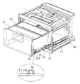
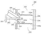
- FIG. 13 is a view showing the structure around the drawer-type container 206 in the conventional refrigerator 300. As shown in FIG.
- the conventional refrigerator 300 includes a box body 208.
- the space in the box 208 is partitioned by two partition walls 208a. Thereby, the storage room 220, the storage room 230, and the storage room 240 are formed in the box 208.
- the door 202 is provided in the opening part 204 of the front surface of the storage chamber 220, and the frame 203 is connected near the center part of the door 202 in the up-down direction.
- the container 206 accommodated in the storage chamber 220 has a flange portion 205.
- the frame 203 detachably supports the container 206 with a flange portion 205.
- the container 206 has an inclined portion 210 having an inclined surface 210a at the lower end of the rear end of the flange portion 205.
- the container 206 can be tilted to an angle at which the container 206 can be taken out of the refrigerator 300 without interference between the container 206 and the door 202.
- the user can remove the container 206 from the refrigerator 300 by tilting the container 206 in this way.
- the container 206 is provided using the space in the storage chamber 230 effectively.
- at least the space below the frame 203 is an invalid space that is not used for storing articles.
- the container 206 needs to be taken out while being inclined, and the container 206 needs to be attached to the frame 203 after being inserted into the storage chamber 230 while being inclined. Therefore, it cannot be said that the container 206 is easily attached and detached.
- the maximum pull-out distance of the container 206 is also restricted by the distance in which the rear portion of the container 206 remains in the storage chamber 230 by the locking projection 203a. For this reason, it is not easy to confirm the entire interior of the container 206, and it cannot be said that it is easy to put food in and out of the container 206.
- a refrigerator that is not a drawer type but has a hinged door with one opening, opens the hinged door, and pulls out the container from the opening of the storage room.
- Such a drawer-type container is required to be easy to put in and take out food and the like, and to be easily attached and detached, like the container that is pulled out integrally with the door.
- the technology for the conventional refrigerator 300 is a technology that enables the container that is pulled out integrally with the door to be attached and detached.
- the present invention has been made in consideration of the above-described conventional problems, and an object of the present invention is to provide a refrigerator including a user-friendly container that is a drawer-type container disposed inside a hinge-type door.
- a refrigerator includes a heat insulating box including an outer box, an inner box, a heat insulating material provided between the outer box and the inner box, and the heat insulation.
- a refrigerator comprising a storage chamber disposed inside the box and having an opening on the front surface, and a hinged door that closes the opening of the storage chamber so as to be openable and closable, and is disposed in the storage chamber.
- the rail member moves forward By sliding with the fixing member while being supported by the fixing member, the position of the rear end of the container in the front-rear direction is another component of the refrigerator than the front end of the component above the container. Also extends to the front position.
- the maximum pull-out distance of the container is a distance at which the position in the front-rear direction of the rear end of the container is a position ahead of the front ends of other components existing above the container.
- the container when the container is pulled out, it can be taken out of the refrigerator by lifting it vertically. That is, the container can be easily taken out from the refrigerator.
- the container when the container is attached to the refrigerator, the container can be attached to the refrigerator by lowering the container vertically from above the rail members with the left and right rail members extended. That is, the container can be easily attached to the refrigerator.
- the present invention can provide a refrigerator that is a drawer-type container disposed inside a hinged door and is easy to use.
- the drawer track means further comprises: another storage chamber disposed above the storage chamber and having an opening on the front surface; and another door for closing the opening of the other storage chamber so that the opening can be opened and closed.
- Another storage chamber disposed above the storage chamber and having an opening on the front surface
- another door for closing the opening of the other storage chamber so that the opening can be opened and closed.
- the position of the rear end of the container in the front-rear direction is a position ahead of the front of the upper storage chamber door.
- the container can be pulled out until Thereby, taking in and out of the food etc. with respect to the said container becomes easy, and attachment or detachment with respect to the refrigerator of the said container becomes easy.
- the other storage chamber disposed above the storage chamber and having an opening on the front surface, and the storage chamber and the other storage chamber are partitioned by vertically dividing an inner space of the heat insulating box.
- a partition for partitioning wherein the door is one door that closes an opening of the storage chamber so as to be openable and closable, and also closes an opening of the other storage chamber so as to be openable and closable. Is extended until the position in the front-rear direction of the rear end of the container is positioned in front of the front end of the partition which is the other end of the refrigerator and the front end of the upper component of the container. Also good.
- the container housed in the lower storage chamber has a position in the front-rear direction of the rear end of the container.
- the container can be pulled out to a position ahead of the front end of the partition.
- the rear end of the container is located up to a position ahead of the front end surface of the partition, so that the container is lifted vertically upward, or Even if it does not reach the place where it is lowered and attached, it can be attached and detached relatively easily while the container is slightly inclined.
- the storage space is located above the container.
- the container When the container is pulled out by opening the door of the storage chamber, the container has a rear end located at a position ahead of the front end surface of the partition, and the container can be opened by opening the door of the storage chamber. Can be attached or detached by lifting the plate vertically upward or down.
- a refrigerator in order to solve the above-described conventional problems, includes an outer box, an inner box, a heat insulating box body including a heat insulating material provided between the outer box and the inner box, A refrigerator comprising a storage chamber disposed inside the heat insulation box and having an opening on a front surface, and a hinged door that closes the opening of the storage chamber so as to be openable and closable, and is disposed in the storage chamber A first container for storing articles; and a drawer track means for supporting the first container so as to be attachable and detachable in the vertical direction, and for extending and retracting to support the first container.
- the track means is elongate in the front-rear direction, a rail member that is detachably attached to each of both ends in the left-right direction at the lower part of the first container, and supports the rail member slidably in the front-rear direction And a fixing member fixed in the storage chamber.
- each of the left and right rail members is attached to the lower part and the left and right ends of the first container.
- the present invention can provide a refrigerator that is a drawer-type container disposed inside a hinged door and is easy to use.
- the first container has attachment holes disposed at both ends in the left and right direction at the lower part of the first container, and the rail member has a protrusion that protrudes upward and engages with the attachment hole.
- the drawer track means supports the first container so as to be detachable in the vertical direction by allowing the protrusions of the left and right rail members to be inserted into and removed from the left and right mounting holes of the first container. You may do that.
- the first container is firmly held by the drawing track means by inserting the protruding portion of the rail member into the mounting hole of the first container.
- the user can easily remove the first container from the drawing track means by lifting the first container upward.
- the first container may be formed of a light-transmitting resin that can visually recognize the stored contents in the first container from the side of the first container. According to this structure, the visibility with respect to the inside of the first container is improved. Further, since the rail member is attached to the lower portion of the first container, the visibility of the inside of the first container from the side is particularly good. Thereby, the user can confirm easily the kind and number, etc. of the foodstuffs accommodated in the 1st container, for example.
- a second container that is shallower than the first container and that supports the left end and the right end of the first container on the left end and the right end of the upper part of the first container may be provided.
- the user can selectively use the first container and the second container.
- the second container suppresses the distortion amount of the first container when a heavy food is stored in the first container.
- the present invention can provide a refrigerator including a user-friendly container that is a drawer-type container disposed inside a hinge-type door.
- FIG. 1 is a front view of the refrigerator according to Embodiment 1 of the present invention.
- FIG. 2 is a longitudinal sectional view of the refrigerator according to the first embodiment.
- FIG. 3 is an enlarged perspective view showing the appearance of the storage case in the first embodiment.
- FIG. 4 is a plan sectional view showing the storage case and the drawer unit according to the first embodiment.
- FIG. 5 is a schematic diagram showing the maximum pull-out distance of the storage case in the first embodiment.
- FIG. 6 is a front view of the refrigerator according to the second embodiment of the present invention.
- FIG. 7 is a schematic diagram showing the maximum pull-out distance of the storage case in the second embodiment.
- FIG. 8A is a view showing a longitudinal section of the storage case in the third embodiment.
- FIG. 8B is a view showing a longitudinal section of a conventional general pull-out type container.
- FIG. 9 is a diagram showing a mounting hole of the storage case and a protruding portion of the rail member in the third embodiment.
- FIG. 10A is a schematic cross-sectional view illustrating a manner in which the accessory case is attached to the storage case in the third embodiment.
- FIG. 10B is a first diagram illustrating another example of how the accessory case is attached to the storage case in the third embodiment.
- FIG. 10C is a second diagram illustrating another example of the attachment of the accessory case to the storage case in the third embodiment.
- FIG. 11 is a schematic diagram showing the maximum pull-out distance of the storage case in the third embodiment.
- FIG. 12 is a schematic diagram showing the maximum pull-out distance of the storage case in the fourth embodiment.
- FIG. 13 is a view showing a structure around a drawer-type container in a conventional refrigerator.
- FIG. 1 is a front view of a refrigerator 100 according to Embodiment 1 of the present invention.
- the refrigerator 100 is a refrigerator including two doors, and includes a storage room partitioned into three in a heat insulating box 70.
- the heat insulation box 70 is constituted by a heat insulation wall in which a foam heat insulation 73 is filled in a space constituted by an inner box 71 obtained by vacuum molding a resin body such as ABS and an outer box 72 using a metal material such as a pre-coated steel plate. Has been.
- the refrigerator 100 includes a refrigerator compartment 10, a vegetable compartment 20, and a freezer compartment 30.
- rectangular dotted lines represent the openings of the respective storage chambers.
- the vegetable compartment 20 accommodates a drawer-type container described later.
- a heat insulating door filled with a foam heat insulating material such as urethane is provided.
- a hinge-type first door 11 is provided that closes the opening of the refrigerator compartment 10 and the vegetable compartment 20 so as to be freely opened and closed.
- the first door 11 is provided with a hinge at the left end, and rotates around a vertical rotation axis.
- the first door 11 is an example of a hinged door in the refrigerator of the present invention.
- the freezer compartment 30 is provided with a drawer-type second door 31.
- the refrigerator compartment 10 is cooled by a direct cooling method, and the vegetable compartment 20 and the freezer compartment 30 are cooled by an indirect cooling method.
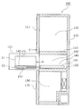
- FIG. 2 is a longitudinal sectional view of the refrigerator 100 according to the first embodiment.
- the refrigerator compartment 10 and the vegetable compartment 20 are partitioned by the upper partition 15 in the heat insulating box 70.
- the vegetable compartment 20 and the freezer compartment 30 are partitioned by a lower partition 25.
- the refrigerator 100 includes two coolers. Specifically, the first cooler 12 is provided on the back side of the back surface 10 a of the refrigerator compartment 10. The back surface 10 a of the refrigerator compartment 10 is cooled by heat conduction from the first cooler 12. The air in the refrigerator compartment 10 is cooled by the cooled back surface 10a.
- the first cooler 12 has a cooling pipe 12a and a metal plate 12b.
- the back surface 10a of the refrigerator compartment 10 is directly cooled by the metal plate 12b attached so as to contact the back side of the back surface 10a.
- the refrigerator 100 includes a second cooler 32 on the back side of the back surface of the freezer compartment 30.
- the inside of the freezer compartment 30 is cooled by circulating the cool air discharged from the second cooler 32.
- the cold air discharged from the second cooler 32 is also supplied to the vegetable compartment 20 and is maintained in a temperature zone between, for example, the temperature zone of the refrigerator compartment 10 and the temperature zone of the freezer compartment 30 by opening / closing control of the damper.
- the vegetable compartment 20 accommodates a drawer-type storage case 21, and the user can pull out the storage case 21 by opening the first door 11.
- the storage case 21 is an example of a container in the refrigerator of the present invention.
- the refrigerator 100 according to the first embodiment is characterized in that food and the like can be easily taken in and out of the storage case 21 and the storage case 21 can be easily attached and detached.
- the storage case 21 and its drawer configuration will be described with reference to FIGS.
- FIG. 3 is an enlarged perspective view showing an appearance of the storage case 21 in the first embodiment.
- the storage case 21 is supported by a rail member 42.
- the rail member 42 is long in the front-rear direction, and is supported by a fixing member 41 fixed in the vegetable compartment 20 so as to be slidable in the front-rear direction.
- the storage case 21 has holding portions 23 that protrude to the outside of the warehouse at both ends in the left-right direction, more specifically, at the bottom of the storage case 21 and at both ends in the left-right direction.
- the holding portion 23 is provided with an attachment hole 23a for detachably attaching the storage case 21 to the rail member 42.
- the rail member 42 is provided with a protruding portion 43 that protrudes upward and engages with the mounting hole 23a.
- Each of the protrusions 43 of the left and right rail members 42 of the storage case 21 can be inserted into and removed from the mounting hole 23a.
- the drawer unit 40 supports the storage case 21 so as to be detachable in the vertical direction.
- the storage case 21 is formed of a light-transmitting resin capable of confirming the storage items in the storage case 21 from the side of the storage case 21. That is, the storage case 21 is made of a resin having a relatively high transparency.
- the type and number of food items stored in the storage case 21 can be easily confirmed from the side of the storage case 21.
- an accessory case 22 shallower than the storage case 21 is detachably attached to the upper part and the rear part of the storage case 21.
- the storage case 21 and the accessory case 22 can be properly used.
- the small case 22 suppresses the amount of distortion of the storage case 21 when a heavy food is stored in the storage case 21.
- the drawer unit 40 is an example of a drawer track means in the refrigerator of the present invention, and is constituted by the left and right rail members 42 and the fixing member 41 of the storage case 21.
- FIG. 4 is a plan sectional view showing the storage case 21 and the drawer unit 40 in the first embodiment.
- the drawer unit 40 includes a fixing member 41 and a rail member 42 arranged on the left and right sides of the storage case 21.
- each of the two rail members 42 includes a middle rail 42a and a support rail 42b.
- the support rail 42b is a rail that directly supports the storage case 21, and is slidable in the front-rear direction with respect to the middle rail 42a. Further, the middle rail 42 a can slide in the front-rear direction with respect to the fixing member 41.
- the entire drawing unit 40 can be expanded and contracted in the front-rear direction.
- the storage case 21 is pulled by the user when the first door 11 rotates as shown in FIG. 4 about the rotation shaft 50 of the hinge, that is, when the first door 11 is opened.
- the drawer unit 40 is extended, and the storage case 21 is pulled out from the vegetable compartment 20.
- the maximum pull-out distance of the storage case 21 is a distance that improves the usability of the storage case 21.
- FIG. 5 is a schematic diagram showing the maximum pull-out distance of the storage case 21 in the first embodiment.
- the position of the rear end A of the storage case 21 in the front-rear direction is more forward than the front end B of the upper partition 15 above the storage case 21. Stretch until positioned.
- the upper partition 15 in this Embodiment 1 is an example of the structure part above the container in the refrigerator of this invention.
- the user can easily confirm what is stored in the storage case 21. Further, when food is stored in the storage case 21, it can be easily stored at any position in the storage case 21.
- the user when taking out food or the like from the storage case 21, the user can easily take out the food at any position in the storage case 21.
- the user can take out the storage case 21 from the refrigerator 100 only by lifting the storage case 21 vertically without performing an operation for avoiding the upper partition 15 such as tilting the storage case 21.
- the user can attach the storage case 21 to the drawer unit 40 only by lowering the storage case 21 from above the rail member 42 while the drawer unit 40 is extended as shown in FIG. it can.
- the refrigerator 100 includes the drawer-type storage case 21 accommodated in the vegetable compartment 20.
- the maximum pull-out distance is a distance at which the position of the rear end A of the storage case 21 in the front-rear direction is positioned forward of the front end B of the upper partition 15 above the storage case 21.
- the user can easily check the stored items in the storage case 21 and put in and out foods from the storage case 21.
- the fact that the storage case 21 is easily attached and detached also means that the ease of cleaning of the storage case 21 is improved, which is very useful for keeping the storage case 21 in which food is stored clean. is there.
- the refrigerator 100 is a refrigerator 100 that is a drawer-type storage case 21 arranged on the inner side of the hinge-type first door 11 and includes an easy-to-use storage case 21.
- FIG. 6 is a front view of the refrigerator 200 according to the second embodiment of the present invention.
- the refrigerator 200 is a refrigerator including three doors, and includes three storage chambers in the heat insulating box 170.
- the refrigerator 200 includes a refrigerator compartment 110, a vegetable compartment 120 whose room temperature can be changed, and a freezer compartment 130.
- a heat insulating door is provided at the opening of each storage room.
- the refrigerator 200 opens and closes the upper door 111 that opens and closes the opening of the refrigerator compartment 110, the middle door 121 that closes the opening of the vegetable compartment 120, and the opening of the freezer compartment 130. And a lower door 131 that is freely closed.
- rectangular dotted lines represent the openings of the respective storage rooms.
- the upper door 111 and the middle door 121 are hinge type doors, each provided with a hinge at the left end, and rotated around a vertical rotation axis.
- the middle door 121 is another example of a hinged door in the refrigerator of the present invention.
- the upper door 111 is an example of the other door in the refrigerator of this invention.
- the cooling method for each of the three storage rooms is the same as that in the first embodiment. That is, the refrigerator compartment 110 is cooled by a direct cooling method, and the vegetable compartment 120 and the freezer compartment 130 are cooled by an indirect cooling method.
- a drawer-type storage case 21 is stored, and is detachably supported by a drawer unit 140 described later.
- the refrigerator 200 of the second embodiment is provided with a door in each of the refrigerator compartment 110 and the vegetable compartment 120.
- the maximum pull-out distance of the storage case 21 in the second embodiment is different from the maximum pull-out distance of the storage case 21 in the first embodiment.
- FIG. 7 is a schematic diagram showing the maximum pull-out distance of the storage case 21 in the second embodiment.
- the storage case 21 is arranged in a vegetable compartment 120 whose upper and lower sides are partitioned by an upper partition 115 and a lower partition 125, and is supported by the drawer unit 140.
- the basic configuration of the drawer unit 140 is the same as that of the drawer unit 40 of the first embodiment, and the fixing member 141 and the rail member 142 arranged on the left and right sides (the back side and the near side in FIG. 7) of the storage case 21, respectively. And have.
- the rail member 142 is composed of two rails that slide on each other.
- the rail member 142 is provided with a protruding portion 143 and engages with the mounting hole 23a of the storage case 21 so as to be able to be put in and out. That is, the storage case 21 is detachably supported by the rail member 142 in the vertical direction.
- the drawer unit 140 has the same basic configuration as the drawer unit 40 of the first embodiment. However, the drawer unit 140 is configured such that the maximum drawer distance of the storage case 21 is longer than the maximum drawer distance by the drawer unit 40 of the first embodiment.
- the drawer unit 140 is positioned until the position of the rear end A of the storage case 21 in the front-rear direction (left-right direction in FIG. 7) is more forward than the front surface C of the upper door 111 above the storage case 21. Elongate.
- the user can easily check the contents of the storage case 21 and easily put food in and out of the storage case 21.
- a relatively large food can be taken in and out of the storage case 21.
- the storage case 21 when the storage case 21 is pulled out to the maximum pull-out distance and is removed from the rail member 142 by lifting the storage case 21, the storage case 21 does not interfere with the upper door 111 that is another component.
- the user can remove the storage case 21 from the rail member 142 only by lifting the storage case 21 upward without performing an operation for avoiding the upper door 111.
- the user can attach the storage case 21 to the rail member 142 only by the operation of lowering the storage case 21 toward the rail member 42.
- the refrigerator 200 according to the second embodiment is a refrigerator 200 that is a drawer-type storage case 21 disposed inside the hinged inner door 121 and includes the user-friendly storage case 21.
- the drawer unit 140 may extend until the position in the front-rear direction of the rear end A of the storage case 21 is located between the front end of the upper partition 115 and the front surface C of the upper door 111.
- the upper door 111 may not be a substantial obstacle that hinders the usability of the storage case 21.
- the storage case 21 can be taken out of the refrigerator 200 without causing the rear end of the storage case 21 to interfere with the upper door 111.
- the operation necessary for taking out the storage case 21 is not only the operation of lifting the storage case 21 vertically.
- the operation for avoiding the upper door 111 required when taking out the storage case 21 is very small.
- the presence of the upper door 111 does not become an obstacle that significantly reduces the confirmation of the contents and the ease of taking in and out the food.
- the drawer unit 140 is extended until the position in the front-rear direction of the rear end A of the storage case 21 is located between the front end of the upper partition 115 and the front surface C of the upper door 111.
- the convenience of the storage case 21 is better than that of a conventional drawer-type container.
- the rear end of the container is located up to a position ahead of the front end surface of the partition, so that the container is lifted vertically upward, or Even if it does not reach the place where it is lowered and attached, it can be attached and detached relatively easily while the container is slightly inclined.
- the storage space is located above the container.
- the rear end of the container is positioned to a position ahead of the front end surface of the partition.
- the container can be attached or detached by lifting it vertically upward or lowering it.
- the direct cooling method and the indirect cooling method are adopted as the cooling methods for the three storage rooms.
- the cooling method of each storage room is not limited to a specific one.
- all of the refrigerator compartment 10, the vegetable compartment 20, and the freezer compartment 30 may be cooled by an indirect cooling method.
- each storage room is not limited to the type described in the first and second embodiments.
- the vegetable room 20 and the vegetable room 120 may be a storage room called a variable temperature room in which a user can set a temperature zone.
- the hinge type doors such as the first door 11 and the middle door 121 are so-called single-open doors.
- the hinged doors such as the first door 11 and the middle door 121 are double doors in which each of the two door plates arranged on the left and right pivots around a pivot axis near the outer edge. There may be.
- one first door 11 may be constituted by two door plates. The same applies to the middle door 121.
- the effect of improving the usability of the storage case 21, which is the effect of the present invention is exhibited without depending on the type of storage room, the cooling method, and the like.
- FIGS. A front view, a longitudinal sectional view, an enlarged perspective view showing the appearance of the storage case, and a plan sectional view showing the storage case and the drawer unit of the refrigerator 100 according to the third embodiment of the present invention are shown in FIGS. Since it is the same as the front view of the refrigerator 100 of Embodiment 1, the longitudinal cross-sectional view, the expansion perspective view which shows the external appearance of a storage case, and the plane sectional view which shows a storage case and a drawer unit, description is abbreviate
- the storage case 21 shown in FIG. 2 is an example of a first container in the refrigerator of the present invention.
- the accessory case 22 is an example of a second container in the refrigerator of the present invention. The manner in which the accessory case 22 is attached to the storage case 21 will be described later with reference to FIG. 10A.
- the storage case 21 is provided by effectively using the space in the vegetable compartment 20.
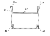
- FIG. 8A is a diagram showing a longitudinal section of the storage case 21 according to the third embodiment
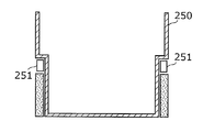
- FIG. 8B is a diagram showing a longitudinal section of a conventional general drawer-type container 250.
- the left and right rail members 251 are generally attached to the center in the vertical direction at both ends of the container 250.
- the left and right rail members 42 are attached to the lower portion and the end portion of the storage case 21.
- the storage case 21 according to the third embodiment is provided in the refrigerator 100 by effectively using an invalid space existing outside the conventional container 250.
- the storage capacity is larger when the storage case 21 is provided.
- the storage case 21 is formed of a highly transparent resin, and the rail member 42 is disposed at the lower part of the storage case 21. Therefore, the visibility inside the storage case 21 when the storage case 21 is viewed from the side is very good.
- the user can easily check the type and number of food items stored in the storage case 21 from the side of the storage case 21.
- the storage case 21 is securely attached to the rail member 42, so that it is firmly held by the drawer unit 40 and can be easily detached from the rail member 42.
- FIG. 9 is a diagram showing the mounting hole 23a of the storage case 21 and the protrusion 43 of the rail member 42 in the third embodiment.
- the rail member 42 has a protrusion 43 near the tip of the support rail 42b.
- the protrusion part 43 has an elastic member which the upper end part and the lower end part inclined before and after (left and right in FIG. 9).
- the width in the front-rear direction of the protruding portion 43 is larger than the width of the mounting hole 23 a arranged in the holding portion 23 of the storage case 21.
- the protrusion 43 is inserted into the attachment hole 23a while reducing the width.
- the storage case 21 is firmly held by the drawer unit 40 by the protrusion 43 being inserted into the mounting hole 23a of the storage case 21.
- the protruding portion 43 is extracted from the mounting hole 23a while reducing the width.
- the storage case 21 can be easily detached from the rail member 42 by lifting the storage case 21 upward with respect to the rail member 42.
- the accessory case 22 is detachably attached to the storage case 21.
- the amount of distortion of the storage case 21 is suppressed.
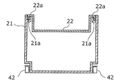
- FIG. 10A is a schematic cross-sectional view showing an aspect of attachment of the accessory case 22 to the storage case 21 in the third embodiment.
- the accessory case 22 is provided with locking portions 22a having return portions downward at both ends.
- the accessory case 22 is attached to the storage case 21 so that these locking portions 22 a are hung on the upper ends of the left and right side walls of the storage case 21.
- the user can use the storage case 21 and the accessory case 22 properly.
- the amount of inclination of the side wall of the storage case 21 when the heavy food is stored in the storage case 21 is suppressed. That is, the distortion amount of the storage case 21 is suppressed by the accessory case 22.
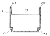
- FIG. 1 Another aspect may be sufficient as the aspect of attachment with respect to the storage case 21 of the accessory case 22.
- a mounting portion 21a having a groove may be provided on the inner upper ends of the left and right side walls of the storage case 21.
- the accessory case 22 is attached to the storage case 21 by inserting the engaging portions 22a at both ends of the accessory case 22 into the grooves of the left and right attachment portions 21a.
- the accessory case 22 may be attached to the storage case 21 so that a locking portion 22 a having no downward return portion is placed on the upper ends of the left and right side walls of the storage case 21. .
- the accessory case 22 is attached to the storage case 21 so that the left end and the right end of the storage case 21 are supported by the left end and the right end of the upper portion of the storage case 21. The amount of distortion is suppressed.
- the maximum pull-out distance of the storage case 21 is a distance that improves the usability of the storage case 21.
- FIG. 11 is a schematic diagram showing the maximum pull-out distance of the storage case 21 in the third embodiment.
- the position of the rear end A of the storage case 21 in the front-rear direction is more forward than the front end B of the upper partition 15 above the storage case 21. Stretch until positioned.
- the user can easily confirm what is stored in the storage case 21. Further, when food is stored in the storage case 21, it can be easily stored at any position in the storage case 21.
- the user when taking out food or the like from the storage case 21, the user can easily take out the food at any position in the storage case 21.
- the user can take out the storage case 21 from the refrigerator 100 only by lifting the storage case 21 vertically without performing an operation for avoiding the upper partition 15 such as tilting the storage case 21.
- the user can attach the storage case 21 to the drawer unit 40 only by lowering the storage case 21 from above the rail member 42 with the drawer unit 40 extended as shown in FIG. it can.
- the refrigerator 100 includes the drawer-type storage case 21 accommodated in the vegetable compartment 20.
- each of the left and right rail members 42 that support the storage case 21 is attached to the lower portion and the end of the storage case 21.
- the stability when the storage case 21 is pulled out and pushed back is ensured, and the invalid space existing outside the storage case 21 can be minimized. That is, the capacity of the storage case 21 can be increased as compared with the conventional case.
- the storage case 21 is formed of a highly transparent resin and the rail member 42 is disposed at the lower part of the storage case 21, the internal visibility from the side of the storage case 21 is very good.
- the storage case 21 is attached to the rail member 42 by the protrusion 43 of the rail member 42 being inserted into the attachment hole 23 a at the lower part of the storage case 21. Thereby, the storage case 21 is firmly held by the drawer unit 40. Further, the storage case 21 can be easily detached from the drawer unit 40.
- the accessory case 22 is attached to the storage case 21, the amount of distortion of the storage case 21 is suppressed.
- the maximum pull-out distance of the storage case 21 is a distance at which the position of the rear end A of the storage case 21 in the front-rear direction is positioned forward of the front end B of the upper partition 15 above the storage case 21.
- the user can easily check the stored items in the storage case 21 and put in and out foods from the storage case 21.
- the fact that the storage case 21 is easily attached and detached also means that the ease of cleaning of the storage case 21 is improved, which is very useful for keeping the storage case 21 in which food is stored clean. is there.
- the refrigerator 100 is a drawer 100 that is a drawer-type storage case 21 disposed inside the hinge-type first door 11 and has a convenient storage case 21.
- Embodiment 4 As a fourth embodiment, a refrigerator including three doors will be described.
- the front view of the refrigerator 200 of this Embodiment 4 is the same as that of the refrigerator 200 of Embodiment 2 shown by FIG. 6, description is abbreviate
- FIG. 12 is a schematic diagram showing the maximum pull-out distance of the storage case 21 in the fourth embodiment.
- the storage case 21 is arranged in a vegetable compartment 120 whose upper and lower sides are partitioned by an upper partition 115 and a lower partition 125, and is supported by the drawer unit 140.
- the basic configuration of the drawer unit 140 is the same as that of the drawer unit 40 of the third embodiment.
- the fixing member 141 and the rail member 142 are arranged on the left and right sides (the back side and the near side in FIG. 12) of the storage case 21, respectively. And have.
- the rail member 142 is composed of two rails that slide on each other.
- the rail member 142 is provided with a protrusion 143.
- the storage case 21 is attached to the rail member 142 by inserting the protruding portion 143 into the attachment hole 23 a in the lower part of the storage case 21.
- each of the left and right rail members 142 is attached to the lower portion and the end portion of the storage case 21.
- the stability when the storage case 21 is pulled out and pushed back is ensured, and the invalid space existing outside the storage case 21 can be minimized. Moreover, the internal visibility from the side of the storage case 21 is very good.
- the storage case 21 is firmly held by the drawer unit 140 by inserting the protruding portion 143 into the mounting hole 23a at the bottom of the storage case 21. Further, the storage case 21 can be easily detached from the drawer unit 140.
- the drawer unit 140 has the same basic configuration as the drawer unit 40 of the third embodiment. However, the drawer unit 140 is configured such that the maximum pull-out distance of the storage case 21 is longer than the maximum pull-out distance by the pull-out unit 40 of the third embodiment.
- the position of the rear end A of the storage case 21 in the front-rear direction (left-right direction in FIG. 12) is positioned forward of the front surface C of the upper door 111 above the storage case 21. Elongate.
- the user can easily check the contents of the storage case 21 and easily put food in and out of the storage case 21.
- a relatively large food can be taken in and out of the storage case 21.
- the storage case 21 when the storage case 21 is pulled out to the maximum pull-out distance and is removed from the rail member 142 by lifting the storage case 21, the storage case 21 does not interfere with the upper door 111 that is another component.
- the user can remove the storage case 21 from the rail member 142 only by lifting the storage case 21 upward without performing an operation for avoiding the upper door 111.
- the user can attach the storage case 21 to the rail member 142 only by the operation of lowering the storage case 21 toward the rail member 42.
- the refrigerator 200 according to the fourth embodiment is a drawer 200 that is a drawer-type storage case 21 that is arranged inside the hinged inner door 121 and is provided with an easy-to-use storage case 21.
- the drawer unit 140 may extend until the position in the front-rear direction of the rear end A of the storage case 21 is located between the front end of the upper partition 115 and the front surface C of the upper door 111.
- the upper door 111 may not be a substantial obstacle that hinders the usability of the storage case 21.
- the storage case 21 can be taken out of the refrigerator 200 without causing the rear end of the storage case 21 to interfere with the upper door 111.
- the operation necessary for taking out the storage case 21 is not only the operation of lifting the storage case 21 vertically.
- the operation for avoiding the upper door 111 required when taking out the storage case 21 is very small.
- the presence of the upper door 111 does not become an obstacle that significantly reduces the confirmation of the contents and the ease of taking in and out the food.
- the drawer unit 140 is extended until the position in the front-rear direction of the rear end A of the storage case 21 is located between the front end of the upper partition 115 and the front surface C of the upper door 111.
- the convenience of the storage case 21 is better than the conventional drawer-type container.
- the direct cooling method and the indirect cooling method are adopted as the cooling methods for the three storage rooms.
- the cooling method of each storage room is not limited to a specific one.
- all of the refrigerator compartment 10, the vegetable compartment 20, and the freezer compartment 30 may be cooled by an indirect cooling method.
- each storage room is not limited to the type described in the third and fourth embodiments.
- the vegetable room 20 and the vegetable room 120 may be a storage room called a variable temperature room in which a user can set a temperature zone.
- the hinge type doors such as the first door 11 and the middle door 121 are so-called single-open doors.
- the hinged doors such as the first door 11 and the middle door 121 are double doors in which each of the two door plates arranged on the left and right pivots around a pivot axis near the outer edge. There may be.
- one first door 11 may be constituted by two door plates. The same applies to the middle door 121.
- the effect of improving the usability of the storage case 21, which is the effect of the present invention is exhibited without depending on the type of storage room, the cooling method, and the like.
- the present invention can provide a refrigerator including a user-friendly container that is a drawer-type container disposed inside a hinge-type door. Therefore, the present invention is useful as refrigerators of various types and sizes such as home use and business use.
Abstract
ヒンジ式の扉の庫内側に配置される引き出し式の容器であって、使い勝手の良い容器を備える冷蔵庫を提供すること。 断熱箱体(70)と、断熱箱体(70)の内方に配置され前面に開口部を有する野菜室(20)と、野菜室(20)の開口部を開閉自在に閉塞するヒンジ式の第一扉(11)とを備える冷蔵庫(100)であって、野菜室(20)内に配置され、物品を収納する収納ケース(21)と、収納ケース(21)を引き出し可能に支持する引出ユニット(40)とを備え、引出ユニット(40)は、レール部材(42)と、固定部材(41)とを有し、レール部材(42)が前方に移動するように固定部材(41)に支持されながら固定部材(41)と摺動することにより、収納ケース(21)の後端Aの前後方向の位置が、冷蔵庫の他の構成部であって収納ケース(21)の上方の構成部の前端Bよりも前方の位置となるまで伸長する。
Description
本発明は、冷蔵庫に関し、特に引き出し式の容器を備える冷蔵庫に関する。
従来、冷蔵庫は、奥まで無駄なく貯蔵できる、使い勝手がよい等の観点から、引き出し式の容器を備えることが多い。このような引き出し式の容器には各種の食品等が収納されるため、容器の収納容量の増加およびこれら食品等の出し入れの容易性が求められている。
また、容器の清掃等を行う場合、容器を冷蔵庫から取り外す必要がある。そのため、容器の冷蔵庫からの取り外しおよび冷蔵庫への取り付けの容易性も求められている。
そこで、引き出し式の容器の使い勝手を向上させる技術も開示されている(例えば、特許文献1参照)。
図13は、従来の冷蔵庫300における引き出し式の容器206の周辺の構造を示す図である。
図13に示すように、従来の冷蔵庫300は箱体208を備える。箱体208内の空間は、2枚の仕切壁208aで区画されている。これにより、箱体208内に、貯蔵室220、貯蔵室230、および貯蔵室240が形成されている。
貯蔵室220の前面の開口部204には扉202が設けられており、扉202の上下方向の中央部付近にはフレーム203が連結されている。
貯蔵室220の内部に収容された容器206は、フランジ部205を有する。フレーム203は、フランジ部205により容器206を着脱可能に支持している。
使用者により、扉202が引っ張られると、フレーム203に設けられた係止突部203aがローラ207と当接するまで、フレーム203に支持されている容器206が引き出される。
このような容器206の周囲の構造において、容器206はフランジ部205の後端下部に傾斜面210aを有する傾斜部210を有している。
これにより、図13に示すように、容器206と扉202とが干渉することなく容器206を冷蔵庫300から取り出すことができる角度まで、容器206を傾けることができる。
使用者は、このように容器206を傾けることで、容器206を冷蔵庫300から取り外すことができる。
しかしながら上記従来の冷蔵庫300では、容器206は貯蔵室230内の空間を有効に利用して備えられているとは言えない。例えば、少なくともフレーム203の下方の空間は、物品の収納には使用されない無効な空間である。
また、上記従来の冷蔵庫300では、容器206を傾けながら取り出す必要があり、また、容器206を傾けながら貯蔵室230に挿入した後にフレーム203に取り付ける必要がある。従って、容器206の着脱が容易であるとは言えない。
また、容器206の最大引き出し距離も、係止突部203aにより容器206の後部が貯蔵室230内に残る距離に規制されている。そのため、容器206内の全体を確認することは容易ではなく、容器206に対する食品等の出し入れも容易であるとは言えない。
また、引き出し式ではなく、片開きのヒンジ式の扉を備え、ヒンジ式の扉を開けて、貯蔵室の開口部から容器を引き出すタイプの冷蔵庫も存在する。
このような引き出し式の容器も、扉と一体に引き出される容器と同様に、食品等の出し入れの容易性および着脱の容易性等が求められている。
しかし、上記従来の冷蔵庫300についての技術は、扉と一体に引き出される容器の着脱を可能とする技術である。
つまり、容器の着脱の邪魔となる扉が容器の前方に存在することを前提としている技術である。従って、ヒンジ式の扉を開けて引き出される容器の使い勝手を向上させるために適した技術であるとは言えない。
なお、容器の奥行き方向の長さを短くすることで、収納物の確認および容器に対する食品等の出し入れが容易となるとも考えられる。また、容器を引き出して垂直に持ち上げて取り外すことが可能となり、容器の着脱の容易性が向上するとも考えられる。
しかしこの場合、容器の容量が小さくなり、収納量が減少するという問題、および、当該容器を収容する貯蔵室内の無駄な空間が増加するという問題が発生する。
そのため容器の奥行き方向の長さを短くすることは容器の使い勝手を向上させる現実的な方策ではない。
本発明は、上記従来の課題を考慮し、ヒンジ式の扉の庫内側に配置される引き出し式の容器であって使い勝手の良い容器を備える冷蔵庫を提供することを目的とする。
上記従来の課題を解決するために、本発明の一態様に係る冷蔵庫は、外箱と内箱と前記外箱および前記内箱の間に設けた断熱材とからなる断熱箱体と、前記断熱箱体の内方に配置され前面に開口部を有する貯蔵室と、前記貯蔵室の前記開口部を開閉自在に閉塞するヒンジ式の扉とを備える冷蔵庫であって、前記貯蔵室内に配置され、物品を収納する容器と、前記容器を上下方向に着脱可能に支持し、かつ、伸縮することで前記容器を引き出し可能に支持する引出軌道手段とを備え、前記引出軌道手段は、前後方向に長尺状であり前記容器の左右方向の両端部それぞれに着脱可能に取り付けられるレール部材と、前記レール部材を前後方向に摺動可能に支持し、前記貯蔵室内に固定される固定部材とを有し、前記レール部材が前方に移動するように前記固定部材に支持されながら前記固定部材と摺動することにより、前記容器の後端の前後方向の位置が、前記冷蔵庫の他の構成部であって前記容器の上方の構成部の前端よりも前方の位置となるまで伸長する。
この構成により、本発明の冷蔵庫では、ヒンジ式の扉を開けると、左右それぞれをレール部材に支持された容器を引き出すことができる。
また、容器の最大引き出し距離は、容器の後端の前後方向の位置が、容器の上方に存在する他の構成部の前端よりも前方の位置となる距離である。
これにより、容器内の収納物の確認および容器に対する食品等の出し入れ自体の容易性が向上する。また、比較的大きな物品の出し入れも容易になる。
また、容器を引き出した場合、垂直に持ち上げることで容器を冷蔵庫から取り出すことができる。つまり、容器を冷蔵庫から容易に取り出すことができる。
また、容器を冷蔵庫に取り付ける場合も、左右のレール部材が伸長した状態で、これらレール部材の上方から容器を垂直に降ろすことにより、容器を冷蔵庫に取り付けることができる。つまり、容器を容易に冷蔵庫に取り付けることができる。
このように、本発明は、ヒンジ式の扉の庫内側に配置される引き出し式の容器であって使い勝手の良い容器を備える冷蔵庫を提供することができる。
また、さらに、前記貯蔵室の上に配置され前面に開口部を有する他の貯蔵室と、前記他の貯蔵室の開口部を開閉自在に閉塞する他の扉とを備え、前記引出軌道手段は、前記容器の後端の前後方向の位置が、前記冷蔵庫の他の構成部であって前記容器の上方の構成部の前端である前記他の扉の前端よりも前方に位置するまで伸長するとしてもよい。
この構成により、引き出された容器の上方に他の貯蔵室の扉が存在する場合であっても、容器の後端の前後方向の位置が、上の貯蔵室の扉の前面よりも前方の位置となるまで容器を引き出すことができる。これにより、当該容器に対する食品等の出し入れが容易となり、かつ、当該容器の冷蔵庫に対する着脱が容易となる。
また、さらに、前記貯蔵室の上に配置され前面に開口部を有する他の貯蔵室と、前記断熱箱体の内方の空間を上下に仕切ることにより前記貯蔵室と前記他の貯蔵室とを区画する仕切体とを備え、前記扉は、前記貯蔵室の開口部を開閉自在に閉塞するとともに、前記他の貯蔵室の開口部を開閉自在に閉塞する一つの扉であり、前記引出軌道手段は、前記容器の後端の前後方向の位置が、前記冷蔵庫の他の構成部であって前記容器の上方の構成部の前端である前記仕切体の前端よりも前方に位置するまで伸長するとしてもよい。
この構成により、二つの貯蔵室の開閉のために一つのヒンジ式の扉が配置された場合であっても、下の貯蔵室に収容された容器は、容器の後端の前後方向の位置が、仕切体の前端よりも前方の位置となるまで容器を引き出すことができる。これにより、当該容器に対する食品等の出し入れが容易となり、かつ、当該容器の冷蔵庫に対する着脱が容易となる。すなわち、たとえば上の貯蔵室の扉の前面よりは後方であっても、仕切体の前端面よりは前方の位置まで容器の後端が位置することで、容器を鉛直上方に持ち上げて、あるいは、下ろして着脱するところまでは至らなくとも、容器をやや傾けながら比較的容易に着脱することができる。
また、当該貯蔵室の扉を開いた際に、その上部に別の扉を備えた貯蔵室が存在しない場合や、当該貯蔵室内の下部のスペースに容器が備えられて容器の上方には貯蔵空間が形成される場合などは、当該貯蔵室の扉をいて容器を引き出すときに、仕切体の前端面より前方の位置まで容器の後端が位置することで、当該貯蔵室の扉を開けば容器を鉛直上方に持ち上げて、あるいは、下ろして着脱することができる。
また、上記従来の課題を解決するために、本発明の一態様に係る冷蔵庫は、外箱と内箱と前記外箱および前記内箱の間に設けた断熱材とからなる断熱箱体と、前記断熱箱体の内方に配置され前面に開口部を有する貯蔵室と、前記貯蔵室の前記開口部を開閉自在に閉塞するヒンジ式の扉とを備える冷蔵庫であって、前記貯蔵室内に配置され、物品を収納する第一容器と、前記第一容器を上下方向に着脱可能に支持し、かつ、伸縮することで前記第一容器を引き出し可能に支持する引出軌道手段とを備え、前記引出軌道手段は、前後方向に長尺状であり、前記第一容器の下部であって左右方向の両端部それぞれに着脱可能に取り付けられるレール部材と、前記レール部材を前後方向に摺動可能に支持し、前記貯蔵室内に固定される固定部材とを有する。
この構成により、本発明の冷蔵庫では、ヒンジ式の扉を開けると、左右それぞれをレール部材に支持された第一容器を引き出すことができる。
また、左右のレール部材のそれぞれは、第一容器の下部かつ左右の端部に取り付けられている。これにより、第一容器の引き出しおよび押し戻しの際の安定性は担保され、かつ、上記従来の冷蔵庫に存在するような、レール部材の下方の無効な空間を極小化できる。つまり、第一容器の容量を従来よりも増加させることができる。
このように、本発明は、ヒンジ式の扉の庫内側に配置される引き出し式の容器であって使い勝手の良い容器を備える冷蔵庫を提供することができる。
また、前記第一容器は、前記第一容器の下部であって左右方向の両端部に配置された取付穴を有し、前記レール部材は、上方に突出し前記取付穴と係合する突出部を有し、前記引出軌道手段は、左右の前記レール部材の前記突出部が、前記第一容器の左右の前記取付穴に挿抜可能であることにより、前記第一容器を上下方向に着脱可能に支持するとしてもよい。
この構成によれば、レール部材の突出部が第一容器の取付穴に差し込まれることで、第一容器は引出軌道手段にしっかりと保持される。また、使用者は、第一容器を上方に持ち上げることで、第一容器を容易に引出軌道手段から取り外すことができる。
また、前記第一容器は、前記第一容器の側方から前記第一容器内の収納物を視認可能な光透過性のある樹脂で形成されているとしてもよい。この構成によれば、第一容器の内部に対する視認性が向上する。また、レール部材は第一容器の下部に取り付けられるため、特に側方からの第一容器の内部に対する視認性は非常に良好なものとなる。これにより、使用者は、例えば第一容器に収容された食品の種類および数などを容易に確認することができる。
また、さらに、前記第一容器よりも浅く、かつ、前記第一容器の上部の左端部と右端部とに、自身の左端部と右端部とを支持される第二容器を備えるとしてもよい。
これにより、例えば、使用者は、第一容器と第二容器を使い分けることが可能となる。また、例えば、第一容器に重量の大きな食品を収納した場合の第一容器の歪み量が第二容器により抑制される。
本発明は、ヒンジ式の扉の庫内側に配置される引き出し式の容器であって使い勝手の良い容器を備える冷蔵庫を提供することができる。
以下、本発明の冷蔵庫の実施の形態について、図面を参照しながら説明する。なお、この実施の形態によってこの発明が限定されるものではない。
(実施の形態1)
図1は、本発明の実施の形態1の冷蔵庫100の正面図である。
図1は、本発明の実施の形態1の冷蔵庫100の正面図である。
図1に示すように冷蔵庫100は、2つの扉を備える冷蔵庫であり、断熱箱体70内に3つに区画された貯蔵室を備えている。
断熱箱体70は、ABSなどの樹脂体を真空成型した内箱71とプリコート鋼板などの金属材料を用いた外箱72とで構成された空間に発泡断熱材73が充填された断熱壁で構成されている。
断熱箱体70内には、上述の3つの貯蔵室が備えられている。具体的には冷蔵庫100は、冷蔵室10、野菜室20、および冷凍室30を備えている。なお、図では矩形の点線がそれぞれの貯蔵室の開口部を表している。また、野菜室20には、後述する引き出し式の容器が収容されている。
各貯蔵室の開口部には、例えばウレタンのような発泡断熱材を発泡充填した断熱扉が設けられている。
具体的には、冷蔵室10および野菜室20の開口部を開閉自在に閉塞するヒンジ式の第一扉11が設けられている。第一扉11は向かって左の端部にヒンジが設けられており、縦方向の回動軸を中心に回動する。なお、第一扉11は、本発明の冷蔵庫における、ヒンジ式の扉の一例である。
また、冷凍室30には、引き出し式の第二扉31が設けられている。
このような基本構成を有する本実施の形態1の冷蔵庫100では、冷蔵室10は直接冷却方式により冷却され、野菜室20および冷凍室30は間接冷却方式により冷却される。
図2は、本実施の形態1の冷蔵庫100の縦断面図である。
図2に示すように、断熱箱体70内において、冷蔵室10と野菜室20とは、上仕切体15により仕切られている。また、野菜室20と冷凍室30とは下仕切体25により仕切られている。
また、冷蔵庫100は、2つの冷却器を備えている。具体的には、冷蔵室10の奥面10aの裏側に第一冷却器12を備えている。冷蔵室10の奥面10aは第一冷却器12からの熱伝導によって冷却される。冷蔵室10内の空気は、この冷却された奥面10aにより冷却される。
第一冷却器12は、冷却パイプ12aと金属板12bとを有する。冷蔵室10の奥面10aは、奥面10aの裏側に接するように取り付けられた金属板12bにより直接的に冷却される。
また、冷蔵庫100は、冷凍室30の奥面の裏側に第二冷却器32を備える。冷凍室30内は、第二冷却器32から放出される冷気が循環することにより冷却される。
第二冷却器32から放出される冷気は、野菜室20にも供給され、ダンパーの開閉制御により、例えば、冷蔵室10の温度帯と冷凍室30の温度帯との間の温度帯に維持される。
また、野菜室20には、引き出し式の収納ケース21が収容されており、使用者は、第一扉11を開くことにより、収納ケース21を引き出すことができる。なお、収納ケース21は本発明の冷蔵庫における容器の一例である。
本実施の形態1の冷蔵庫100は、収納ケース21に対する食品等の出し入れが容易であり、かつ、収納ケース21の着脱を容易に行うことができるという特徴を有する。以下に、収納ケース21およびその引き出し構成について図3から図5を用いて説明する。
図3は、本実施の形態1における収納ケース21の外観を示す拡大斜視図である。
図3に示すように、収納ケース21はレール部材42に支持されている。また、レール部材42は前後方向に長尺状であり、野菜室20内に固定される固定部材41により前後方向に摺動可能に支持されている。
具体的には、収納ケース21は、左右方向の両端部、より詳しくは収納ケース21の下部であって左右方向の両端部それぞれに庫外側に突出した保持部23を有する。
また、保持部23には、レール部材42に収納ケース21を着脱可能に取り付けるための取付穴23aが配置されている。
レール部材42には、上方に突出し取付穴23aと係合する突出部43が設けられている。収納ケース21の左右のレール部材42の突出部43のそれぞれは、取付穴23aに挿抜可能である。
これにより、引出ユニット40は、収納ケース21は上下方向に着脱可能に支持している。
また、収納ケース21は、収納ケース21の側方から収納ケース21内の収納物を確認可能な光透過性のある樹脂で形成されている。つまり、収納ケース21は、透明度の比較的高い樹脂で作成されている。
これにより、例えば、収納ケース21に収納されている食品の種類および数などを、収納ケース21の側方から容易に確認することができる。
また、収納ケース21の上部かつ後部には、収納ケース21よりも浅い小物ケース22が着脱可能に取り付けられている。これにより、例えば、収納ケース21と小物ケース22との使い分けが可能になる。また、例えば、収納ケース21に重量の大きな食品を収納した場合の収納ケース21の歪み量が小物ケース22により抑制される。
なお、引出ユニット40は、本発明の冷蔵庫における引出軌道手段の一例であり、収納ケース21の左右のレール部材42と固定部材41とにより構成されている。
図4は、本実施の形態1における収納ケース21と引出ユニット40とを示す平面断面図である。
図4に示すように、引出ユニット40は、収納ケース21の左右それぞれに配置された、固定部材41とレール部材42とを有している。
また、2つのレール部材42のそれぞれは、ミドルレール42aと支持レール42bとから構成されている。
支持レール42bは、収納ケース21を直接的に支持するレールであり、ミドルレール42aに対して前後方向に摺動可能である。また、ミドルレール42aは固定部材41に対して前後方向に摺動可能である。
レール部材42がこのような構成であることにより、引出ユニット40全体として前後方向に伸縮することができる。
つまり、第一扉11が、ヒンジの回動軸50を中心に図4に示すように回動した場合、つまり、第一扉11が開かれた場合、収納ケース21が使用者に引っ張られることにより、引出ユニット40が伸長し、収納ケース21は野菜室20から引き出される。
また、収納ケース21の最大引き出し距離は、収納ケース21の使い勝手を向上させる距離である。
図5は、本実施の形態1における収納ケース21の最大引き出し距離を示す概要図である。
図5に示すように、引出ユニット40は、収納ケース21の後端Aの前後方向(図5における左右方向)の位置が、収納ケース21の上方の上仕切体15の前端Bよりも前方に位置するまで伸長する。
なお、本実施の形態1における上仕切体15は、本発明の冷蔵庫における容器の上方の構成部の一例である。
これにより、使用者は、収納ケース21内に何が収容されているかを容易に確認することができる。また、収納ケース21に食品を収める場合に、その収容位置が収納ケース21内のどの位置であっても、容易に収めることができる。
また、使用者は、収納ケース21から食品等を取り出す場合に、その食品の収容位置が収納ケース21内のどの位置であっても、容易に取り出すことができる。
また、収納ケース21に対し、比較的大きな食品を出し入れすることも可能となる。
さらに、使用者は、収納ケース21を傾けるなど、上仕切体15を避けるための動作をすることなく、収納ケース21を垂直に持ち上げるだけで、収納ケース21を冷蔵庫100から取り出すことができる。
また、使用者は、図5に示すように引出ユニット40が伸長している状態で、収納ケース21をレール部材42上方から降ろす動作をするだけで、収納ケース21を引出ユニット40に取り付けることができる。
このように、本実施の形態1の冷蔵庫100は、野菜室20に収容された引き出し式の収納ケース21を備える。また、その最大引き出し距離は、収納ケース21の後端Aの前後方向の位置が、収納ケース21の上方の上仕切体15の前端Bよりも前方に位置する距離である。
これにより、使用者は、収納ケース21内の収納物の確認および収納ケース21に対する食品等の出し入れを容易に行うことができる。
また、収納ケース21の着脱が容易であるということは、収納ケース21の清掃の容易性が向上することをも意味し、食品が収納される収納ケース21を清浄に保つ上で非常に有用である。
このように、本実施の形態1の冷蔵庫100は、ヒンジ式の第一扉11の庫内側に配置される引き出し式の収納ケース21であって使い勝手の良い収納ケース21を備える冷蔵庫100である。
(実施の形態2)
実施の形態2として、扉を三つ備える冷蔵庫について説明する。
実施の形態2として、扉を三つ備える冷蔵庫について説明する。
図6は、本発明の実施の形態2の冷蔵庫200の正面図である。
図6に示すように冷蔵庫200は、三つの扉を備える冷蔵庫であり、断熱箱体170内に三つの貯蔵室を備えている。
具体的には冷蔵庫200は、冷蔵室110、室内の温度が変更可能な野菜室120、および冷凍室130を備えている。
各貯蔵室の開口部には断熱扉が設けられている。具体的には冷蔵庫200は、冷蔵室110の開口部を開閉自在に閉塞する上扉111と、野菜室120の開口部を開閉自在に閉塞する中扉121と、冷凍室130の開口部を開閉自在に閉塞する下扉131とを備える。図では矩形の点線がそれぞれの貯蔵室の開口部を表している。
また、上扉111および中扉121は、ヒンジ式の扉であり、それぞれ、向かって左の端部にヒンジが設けられており、縦方向の回動軸を中心に回動する。
なお、中扉121は、本発明の冷蔵庫におけるヒンジ式の扉の別の一例である。また、上扉111は、本発明の冷蔵庫における他の扉の一例である。
また、上記3つの貯蔵室のそれぞれの冷却方式は、実施の形態1と同じである。すなわち、冷蔵室110は直接冷却方式により冷却され、野菜室120および冷凍室130は間接冷却方式により冷却される。
さらに、野菜室120には、実施の形態1と同じく、引き出し式の収納ケース21が収容されており、後述する引出ユニット140に着脱可能に支持されている。
しかし、実施の形態2の冷蔵庫200は、実施の形態1の冷蔵庫100とは異なり、冷蔵室110と野菜室120のそれぞれに扉が備えられている。
つまり、収納ケース21を引き出す場合に、上扉111が閉められている状態で中扉121を開けると、収納ケース21の、野菜室120の開口部から引き出された部分の上方には上扉111が存在する。
そのため、実施の形態2における収納ケース21の最大引き出し距離は、実施の形態1における収納ケース21の最大引き出し距離と異なる。
図7は、本実施の形態2における収納ケース21の最大引き出し距離を示す概要図である。
図7に示すように、収納ケース21は、上下を上仕切体115と下仕切体125とにより仕切られた野菜室120に配置されており、引出ユニット140に支持されている。
なお、引出ユニット140の基本的な構成は、実施の形態1の引出ユニット40と同じく、収納ケース21の左右(図7において奥側と手前側)それぞれに配置された固定部材141とレール部材142とを有する。
また、レール部材142は、互いに摺動する二つのレールで構成されている。レール部材142には突出部143が設けられており、収納ケース21の取付穴23aに出し入れ可能に係合する。つまり、収納ケース21は上下方向にレール部材142に着脱可能に支持されている。
このように、引出ユニット140は、実施の形態1の引出ユニット40と基本的な構成は同じである。しかし、引出ユニット140は、収納ケース21の最大引き出し距離が、実施の形態1の引出ユニット40による最大引き出し距離よりも長くなるよう構成されている。
具体的には、引出ユニット140は、収納ケース21の後端Aの前後方向(図7における左右方向)の位置が、収納ケース21の上方の上扉111の前面Cよりも前方に位置するまで伸長する。
これにより、使用者は、収納ケース21の内容物の確認および収納ケース21に対する食品等の出し入れを容易に行うことができる。また、収納ケース21に対し、比較的大きな食品を出し入れすることも可能となる。
また、収納ケース21を最大引き出し距離まで引き出して、収納ケース21を持ち上げることによりレール部材142から取り外す場合、収納ケース21が、他の構成部である上扉111と干渉することがない。
つまり、実施の形態1と同じく、使用者は、上扉111を避けるための動作をすることなく、収納ケース21を上方に持ち上げる動作のみで、収納ケース21をレール部材142から取り外すことができる。
また、使用者は収納ケース21をレール部材42に向かって降ろす動作のみで、収納ケース21をレール部材142に取り付けることができる。
このように、本実施の形態2の冷蔵庫200は、ヒンジ式の中扉121の庫内側に配置される引き出し式の収納ケース21であって使い勝手の良い収納ケース21を備える冷蔵庫200である。
なお、引出ユニット140は、収納ケース21の後端Aの前後方向の位置が、上仕切体115の前端と、上扉111の前面Cとの間に位置するまで伸長してもよい。
これは、収納ケース21が最大引き出し位置にある状態において、収納ケース21の後端Aの前後方向の位置が上扉111の前面Cよりも前方に位置しない場合であっても、後端Aが上仕切体115の前端よりも前方に位置すれば、従来よりも収納ケース21の使い勝手は向上するからである。
つまり、上扉111が収納ケース21の使い勝手の向上を妨げる実質的な障害とはならない場合があるからである。
例えば、収納ケース21の前端を上に持ち上げて僅かに前方に移動させることで、収納ケース21の後端部を上扉111と干渉させることなく、収納ケース21を冷蔵庫200から取り出すことができる。
すなわち、収納ケース21の取り出しに必要な動作は、収納ケース21を垂直に持ち上げる動作のみではない。しかし、特に上扉111の厚みが比較的薄い場合などでは、収納ケース21を取り出す際に必要な、上扉111を避けるための動作はごく僅かである。
また、収納ケース21の後端Aの前後方向の位置が、上仕切体115の前端よりも前方にある場合、収納ケース21のほとんどと言っていい部分が冷蔵庫200外に引き出されていることになる。
そのため、上扉111の存在が、内容物の確認および食品等の出し入れの容易性を著しく低下させるほどの障害とはならない。
このように、引出ユニット140が、収納ケース21の後端Aの前後方向の位置が、上仕切体115の前端と、上扉111の前面Cとの間に位置するまで伸長する場合であっても、収納ケース21の使い勝手は、従来の引き出し式の容器よりも良いと言える。
すなわち、たとえば上の貯蔵室の扉の前面よりは後方であっても、仕切体の前端面よりは前方の位置まで容器の後端が位置することで、容器を鉛直上方に持ち上げて、あるいは、下ろして着脱するところまでは至らなくとも、容器をやや傾けながら比較的容易に着脱することができる。
また、当該貯蔵室の扉を開いた際に、その上部に別の扉を備えた貯蔵室が存在しない場合や、当該貯蔵室内の下部のスペースに容器が備えられて容器の上方には貯蔵空間が形成される場合などは、当該貯蔵室の扉を開いて容器を引き出すときに、仕切体の前端面より前方の位置まで容器の後端が位置することで、当該貯蔵室の扉を開けば容器を鉛直上方に持ち上げて、あるいは、下ろして着脱することができる。
このようにして、容器内の視認性が従来と比べて実用上十分に高められると同時に、容器の着脱性は実質的に極めて良好なものとなり、容器を取り外して洗浄し、衛生的な環境に保ちたいという近年高まる消費者ニーズに即した、使い勝手のよい引き出し容器構造を提供できる実用効果の高いものとなる。
以上説明した実施の形態1および2において、3つの貯蔵室の冷却方式として、直接冷却方式と間接冷却方式とが採用されているとした。しかし、本発明の実施に際し、各貯蔵室の冷却方式は特定なものに限定されない。
例えば、実施の形態1の冷蔵庫100において、冷蔵室10、野菜室20および冷凍室30の全てが間接冷却方式により冷却されてもよい。実施の形態2の冷蔵庫200についても同様である。
また、各貯蔵室の種類も実施の形態1および2で説明した種類に限定されない。例えば、野菜室20および野菜室120が、使用者が温度帯の設定が可能な変温室と呼ばれる貯蔵室であってもよい。
また、第一扉11および中扉121等のヒンジ式の扉は、いわゆる片開き式の扉である。しかしながら、第一扉11および中扉121等のヒンジ式の扉は、左右に並ぶ2枚の扉板のそれぞれが、外側の端辺付近の回動軸を中心に回動する観音開き式の扉であってもよい。
つまり、2枚の扉板により一つの第一扉11が構成されていてもよい。中扉121も同様である。
つまり、本発明の効果である収納ケース21の使い勝手の向上という効果は、貯蔵室の種類および冷却方式等に依存することなく発揮される。
(実施の形態3)
本発明の実施の形態3の冷蔵庫100の正面図、縦断面図、収納ケースの外観を示す拡大斜視図、および収納ケースと引出ユニットとを示す平面断面図は、図1~図4に示された実施の形態1の冷蔵庫100の正面図、縦断面図、収納ケースの外観を示す拡大斜視図、および収納ケースと引出ユニットとを示す平面断面図と同様であるため、説明を省略する。
本発明の実施の形態3の冷蔵庫100の正面図、縦断面図、収納ケースの外観を示す拡大斜視図、および収納ケースと引出ユニットとを示す平面断面図は、図1~図4に示された実施の形態1の冷蔵庫100の正面図、縦断面図、収納ケースの外観を示す拡大斜視図、および収納ケースと引出ユニットとを示す平面断面図と同様であるため、説明を省略する。
なお、図2に示された収納ケース21は、本発明の冷蔵庫における第一容器の一例である。また、小物ケース22は、本発明の冷蔵庫における第二容器の一例である。また、小物ケース22の収納ケース21に対する取り付けの態様については、図10Aを用いて後述する。
また、図2及び図4に示されたように、このような構成を有する冷蔵庫100では、収納ケース21は野菜室20内の空間を有効に利用して設けられている。
図8Aは、本実施の形態3における収納ケース21の縦断面を示す図であり、図8Bは、従来の一般的な引き出し式の容器250の縦断面を示す図である。
図8Bに示すように、従来の引き出し式の容器250では、容器250の両端の上下方向の中央部に左右のレール部材251が取り付けられることが一般的である。
そのため、レール部材251の下方に、食品等の収納に使用されない無効な空間(図8Bではドットが付された領域)が存在する。
一方、図8Aに示すように、本実施の形態3において、左右のレール部材42は収納ケース21の下部かつ端部に取り付けられている。
つまり、本実施の形態3の収納ケース21は、従来の容器250の外方に存在していた無効な空間を有効に利用して、冷蔵庫100に備えられている。
すなわち、同じ大きさの貯蔵室に収納ケース21を備えた場合と、容器250を備えた場合とを想定すると、収納ケース21備えた場合の方が収納容量は大きくなる。
また、収納ケース21が透明度の高い樹脂で形成され、かつ、レール部材42が収納ケース21の下部に配置されている。そのため、収納ケース21を側方から見た場合の、収納ケース21内部の視認性が非常に良好である。
これにより、使用者は、収納ケース21に収納されている食品の種類および数などを、収納ケース21の側方から容易に確認することができる。
また、収納ケース21は、レール部材42に確実に取り付けられることで、引出ユニット40にしっかりと保持され、かつ、容易にレール部材42から取り外しが可能である。
図9は、本実施の形態3における、収納ケース21の取付穴23aと、レール部材42の突出部43とを示す図である。
図9に示すように、レール部材42は、支持レール42bの先端近くに突出部43を有している。また、突出部43は、前後(図9においては左右)に、上端部と下端部とが傾斜した弾性部材を有する。
突出部43の前後方向の幅は、収納ケース21の保持部23に配置された取付穴23aの幅よりも大きい。
しかし、収納ケース21がレール部材42に取り付けられる場合、突出部43は幅を縮めながら取付穴23aに挿入される。
このように、収納ケース21の取付穴23aに突出部43が差し込まれることにより、収納ケース21は引出ユニット40にしっかりと保持される。
また、収納ケース21がレール部材42から取り外される場合、突出部43は幅を縮めながら取付穴23aから抜き出される。
つまり、図9に示すように、レール部材42に対し収納ケース21を上方に持ち上げることで、容易に収納ケース21をレール部材42から取り外すことが出来る。
また、上述のように、収納ケース21には小物ケース22が着脱可能に取り付けられている。この小物ケース22により、収納ケース21の歪み量は抑制される。
図10Aは、本実施の形態3における小物ケース22の収納ケース21に対する取り付けの態様を示す断面概要図である。
図10Aに示すように、小物ケース22は、両端部に、下方への返し部分を有する係止部22aを備えている。
これら係止部22aが、収納ケース21の左右の側壁の上端に掛けられるようにして小物ケース22が収納ケース21に取り付けられる。
このように、収納ケース21に小物ケース22を取り付けることにより、例えば、使用者は、収納ケース21と小物ケース22との使い分けが可能になる。
また、例えば、収納ケース21に重量の大きな食品を収納した場合の収納ケース21の側壁の外方への傾き量が抑制される。つまり、収納ケース21の歪み量が小物ケース22により抑制される。
なお、小物ケース22の収納ケース21に対する取り付けの態様は別の態様であってもよい。
例えば、図10Bに示すように、収納ケース21の左右の側壁の内側上端部に、溝を有する取付部21aを備えてもよい。
この場合、この左右の取付部21aの溝に、小物ケース22の両端部の係止部22aが挿入されることで、小物ケース22が収納ケース21に取り付けられる。
収納ケース21と小物ケース22とをこのような形状にすることでも、収納ケース21の歪み量が小物ケース22により抑制される。
また、例えば、図10Cに示すように、収納ケース21の左右の側壁の上端に、下方への返し部分のない係止部22aを載せるようにして小物ケース22を収納ケース21に取り付けてもよい。
この場合、少なくとも、収納ケース21の側壁の内方への傾き量が抑制される。つまり、収納ケース21の歪み量が小物ケース22により抑制される。
このように、小物ケース22が、収納ケース21の上部の左端部と右端部とに自身の左端部と右端部とを支持されるように、収納ケース21に取り付けられることにより、収納ケース21の歪み量が抑制される。
これにより、例えば、収納ケース21の変形、および変形に伴う収納ケース21の出し入れ時の円滑性の低下が防止される。
また、収納ケース21の最大引き出し距離は、収納ケース21の使い勝手を向上させる距離である。
図11は、本実施の形態3における収納ケース21の最大引き出し距離を示す概要図である。
図11に示すように、引出ユニット40は、収納ケース21の後端Aの前後方向(図11における左右方向)の位置が、収納ケース21の上方の上仕切体15の前端Bよりも前方に位置するまで伸長する。
これにより、使用者は、収納ケース21内に何が収容されているかを容易に確認することができる。また、収納ケース21に食品を収める場合に、その収容位置が収納ケース21内のどの位置であっても、容易に収めることができる。
また、使用者は、収納ケース21から食品等を取り出す場合に、その食品の収容位置が収納ケース21内のどの位置であっても、容易に取り出すことができる。
また、収納ケース21に対し、比較的大きな食品を出し入れすることも可能となる。
さらに、使用者は、収納ケース21を傾けるなど、上仕切体15を避けるための動作をすることなく、収納ケース21を垂直に持ち上げるだけで、収納ケース21を冷蔵庫100から取り出すことができる。
また、使用者は、図11に示すように引出ユニット40が伸長している状態で、収納ケース21をレール部材42上方から降ろす動作をするだけで、収納ケース21を引出ユニット40に取り付けることができる。
このように、本実施の形態3の冷蔵庫100は、野菜室20に収容された引き出し式の収納ケース21を備える。
また、収納ケース21を支持する左右のレール部材42のそれぞれは、収納ケース21の下部かつ端部に取り付けられる。
これにより、収納ケース21の引き出しおよび押し戻しの際の安定性は担保され、かつ、収納ケース21の外側に存在する無効な空間を極小化できる。つまり、収納ケース21の容量を従来よりも増加させることができる。
また、収納ケース21が透明度の高い樹脂で形成され、かつ、レール部材42が収納ケース21の下部に配置されているため、収納ケース21側方からの内部の視認性が非常に良好である。
また、レール部材42の突出部43が、収納ケース21の下部の取付穴23aに挿入されることで、収納ケース21がレール部材42に取り付けられる。これにより、収納ケース21は引出ユニット40にしっかりと保持される。また、引出ユニット40から収納ケース21を容易に取り外すことができる。
また、小物ケース22が収納ケース21に取り付けられていることにより、収納ケース21の歪み量が抑制される。
また、その収納ケース21の最大引き出し距離は、収納ケース21の後端Aの前後方向の位置が、収納ケース21の上方の上仕切体15の前端Bよりも前方に位置する距離である。
これにより、使用者は、収納ケース21内の収納物の確認および収納ケース21に対する食品等の出し入れを容易に行うことができる。
また、収納ケース21の着脱が容易であるということは、収納ケース21の清掃の容易性が向上することをも意味し、食品が収納される収納ケース21を清浄に保つ上で非常に有用である。
このように、本実施の形態3の冷蔵庫100は、ヒンジ式の第一扉11の庫内側に配置される引き出し式の収納ケース21であって使い勝手の良い収納ケース21を備える冷蔵庫100である。
(実施の形態4)
実施の形態4として、扉を三つ備える冷蔵庫について説明する。なお、本実施の形態4の冷蔵庫200の正面図は、図6に示された実施の形態2の冷蔵庫200の正面図と同様であるため、説明を省略する。
実施の形態4として、扉を三つ備える冷蔵庫について説明する。なお、本実施の形態4の冷蔵庫200の正面図は、図6に示された実施の形態2の冷蔵庫200の正面図と同様であるため、説明を省略する。
図12は、本実施の形態4における収納ケース21の最大引き出し距離を示す概要図である。
図12に示すように、収納ケース21は、上下を上仕切体115と下仕切体125とにより仕切られた野菜室120に配置されており、引出ユニット140に支持されている。
なお、引出ユニット140の基本的な構成は、実施の形態3の引出ユニット40と同じく、収納ケース21の左右(図12において奥側と手前側)それぞれに配置された固定部材141とレール部材142とを有する。
また、レール部材142は、互いに摺動する二つのレールで構成されている。レール部材142には突出部143が設けられている。突出部143が収納ケース21の下部の取付穴23aに挿入されることで、収納ケース21がレール部材142に取り付けられる。
つまり、実施の形態3と同様に、左右のレール部材142のそれぞれは、収納ケース21の下部かつ端部に取り付けられる。
そのため、実施の形態3の冷蔵庫100と同じく、収納ケース21の引き出しおよび押し戻しの際の安定性は担保され、かつ、収納ケース21の外側に存在する無効な空間を極小化できる。また、収納ケース21側方からの内部の視認性が非常に良好である。
さらに、突出部143が収納ケース21の下部の取付穴23aに挿入されることで、収納ケース21は引出ユニット140にしっかりと保持される。また、引出ユニット140から収納ケース21を容易に取り外すことができる。
このように、引出ユニット140は、実施の形態3の引出ユニット40と基本的な構成は同じである。しかし、引出ユニット140は、収納ケース21の最大引き出し距離が、実施の形態3の引出ユニット40による最大引き出し距離よりも長くなるよう構成されている。
具体的には、引出ユニット140は、収納ケース21の後端Aの前後方向(図12における左右方向)の位置が、収納ケース21の上方の上扉111の前面Cよりも前方に位置するまで伸長する。
これにより、使用者は、収納ケース21の内容物の確認および収納ケース21に対する食品等の出し入れを容易に行うことができる。また、収納ケース21に対し、比較的大きな食品を出し入れすることも可能となる。
また、収納ケース21を最大引き出し距離まで引き出して、収納ケース21を持ち上げることによりレール部材142から取り外す場合、収納ケース21が、他の構成部である上扉111と干渉することがない。
つまり、実施の形態3と同じく、使用者は、上扉111を避けるための動作をすることなく、収納ケース21を上方に持ち上げる動作のみで、収納ケース21をレール部材142から取り外すことができる。
また、使用者は収納ケース21をレール部材42に向かって降ろす動作のみで、収納ケース21をレール部材142に取り付けることができる。
このように、本実施の形態4の冷蔵庫200は、ヒンジ式の中扉121の庫内側に配置される引き出し式の収納ケース21であって使い勝手の良い収納ケース21を備える冷蔵庫200である。
なお、引出ユニット140は、収納ケース21の後端Aの前後方向の位置が、上仕切体115の前端と、上扉111の前面Cとの間に位置するまで伸長してもよい。
これは、収納ケース21が最大引き出し位置にある状態において、収納ケース21の後端Aの前後方向の位置が上扉111の前面Cよりも前方に位置しない場合であっても、後端Aが上仕切体115の前端よりも前方に位置すれば、従来よりも収納ケース21の使い勝手は向上するからである。
つまり、上扉111が収納ケース21の使い勝手の向上を妨げる実質的な障害とはならない場合があるからである。
例えば、収納ケース21の前端を上に持ち上げて僅かに前方に移動させることで、収納ケース21の後端部を上扉111と干渉させることなく、収納ケース21を冷蔵庫200から取り出すことができる。
すなわち、収納ケース21の取り出しに必要な動作は、収納ケース21を垂直に持ち上げる動作のみではない。しかし、特に上扉111の厚みが比較的薄い場合などでは、収納ケース21を取り出す際に必要な、上扉111を避けるための動作はごく僅かである。
また、収納ケース21の後端Aの前後方向の位置が、上仕切体115の前端よりも前方にある場合、収納ケース21のほとんどと言っていい部分が冷蔵庫200外に引き出されていることになる。
そのため、上扉111の存在が、内容物の確認および食品等の出し入れの容易性を著しく低下させるほどの障害とはならない。
このように、引出ユニット140が、収納ケース21の後端Aの前後方向の位置が、上仕切体115の前端と、上扉111の前面Cとの間に位置するまで伸長する場合であっても、収納ケース21の使い勝手は、従来の引き出し式の容器よりも良いと言える。
(実施の形態3および4の補足事項)
以上説明した実施の形態3および4において、3つの貯蔵室の冷却方式として、直接冷却方式と間接冷却方式とが採用されているとした。しかし、本発明の実施に際し、各貯蔵室の冷却方式は特定なものに限定されない。
以上説明した実施の形態3および4において、3つの貯蔵室の冷却方式として、直接冷却方式と間接冷却方式とが採用されているとした。しかし、本発明の実施に際し、各貯蔵室の冷却方式は特定なものに限定されない。
例えば、実施の形態3の冷蔵庫100において、冷蔵室10、野菜室20および冷凍室30の全てが間接冷却方式により冷却されてもよい。実施の形態4の冷蔵庫200についても同様である。
また、各貯蔵室の種類も実施の形態3および4で説明した種類に限定されない。例えば、野菜室20および野菜室120が、使用者が温度帯の設定が可能な変温室と呼ばれる貯蔵室であってもよい。
また、第一扉11および中扉121等のヒンジ式の扉は、いわゆる片開き式の扉である。しかしながら、第一扉11および中扉121等のヒンジ式の扉は、左右に並ぶ2枚の扉板のそれぞれが、外側の端辺付近の回動軸を中心に回動する観音開き式の扉であってもよい。
つまり、2枚の扉板により一つの第一扉11が構成されていてもよい。中扉121も同様である。
つまり、本発明の効果である収納ケース21の使い勝手の向上という効果は、貯蔵室の種類および冷却方式等に依存することなく発揮される。
以上、本発明に係る冷蔵庫について、上記実施の形態を用いて説明したが、本発明は、これに限定されるものではない。
つまり、今回開示された実施の形態はすべての点で例示であって制限的なものではないと考えられるべきである。本発明の範囲は上記した説明ではなくて請求の範囲によって示され、請求の範囲と均等の意味及び範囲内でのすべての変更が含まれることが意図される。
また、発明の趣旨を逸脱しない範囲で、上記複数の実施の形態における各構成要素を任意に組み合わせても良い。
本発明は、ヒンジ式の扉の庫内側に配置される引き出し式の容器であって、使い勝手の良い容器を備える冷蔵庫を提供することができる。従って、本発明は、家庭用および業務用など様々な種類および大きさの冷蔵庫等として有用である。
10、110 冷蔵室
10a 奥面
11 第一扉
12 第一冷却器
12a 冷却パイプ
12b 金属板
15、115 上仕切体
20、120 野菜室
21 収納ケース
21a 取付部
22 小物ケース
22a 係止部
23 保持部
23a 取付穴
25、125 下仕切体
30、130 冷凍室
31 第二扉
32 第二冷却器
40、140 引出ユニット
41、141 固定部材
42、142、251 レール部材
42a ミドルレール
42b 支持レール
43、143 突出部
50 回動軸
70、170 断熱箱体
71 内箱
72 外箱
73 発泡断熱材
100、200 冷蔵庫
111 上扉
121 中扉
131 下扉
10a 奥面
11 第一扉
12 第一冷却器
12a 冷却パイプ
12b 金属板
15、115 上仕切体
20、120 野菜室
21 収納ケース
21a 取付部
22 小物ケース
22a 係止部
23 保持部
23a 取付穴
25、125 下仕切体
30、130 冷凍室
31 第二扉
32 第二冷却器
40、140 引出ユニット
41、141 固定部材
42、142、251 レール部材
42a ミドルレール
42b 支持レール
43、143 突出部
50 回動軸
70、170 断熱箱体
71 内箱
72 外箱
73 発泡断熱材
100、200 冷蔵庫
111 上扉
121 中扉
131 下扉
Claims (7)
- 外箱と内箱と前記外箱および前記内箱の間に設けた断熱材とからなる断熱箱体と、前記断熱箱体の内方に配置され前面に開口部を有する貯蔵室と、前記貯蔵室の前記開口部を開閉自在に閉塞するヒンジ式の扉とを備える冷蔵庫であって、
前記貯蔵室内に配置され、物品を収納する容器と、
前記容器を上下方向に着脱可能に支持し、かつ、伸縮することで前記容器を引き出し可能に支持する引出軌道手段とを備え、
前記引出軌道手段は、
前後方向に長尺状であり前記容器の左右方向の両端部それぞれに着脱可能に取り付けられるレール部材と、
前記レール部材を前後方向に摺動可能に支持し、前記貯蔵室内に固定される固定部材とを有し、
前記レール部材が前方に移動するように前記固定部材に支持されながら前記固定部材と摺動することにより、前記容器の後端の前後方向の位置が、前記冷蔵庫の他の構成部であって前記容器の上方の構成部の前端よりも前方の位置となるまで伸長する
冷蔵庫。 - さらに、
前記貯蔵室の上に配置され前面に開口部を有する他の貯蔵室と、
前記他の貯蔵室の開口部を開閉自在に閉塞する他の扉とを備え、
前記引出軌道手段は、前記容器の後端の前後方向の位置が、前記冷蔵庫の他の構成部であって前記容器の上方の構成部の前端である前記他の扉の前面よりも前方に位置するまで伸長する
請求項1に記載の冷蔵庫。 - さらに、
前記貯蔵室の上に配置され前面に開口部を有する他の貯蔵室と、
前記断熱箱体の内方の空間を上下に仕切ることにより前記貯蔵室と前記他の貯蔵室とを区画する仕切体とを備え、
前記扉は、前記貯蔵室の開口部を開閉自在に閉塞するとともに、前記他の貯蔵室の開口部を開閉自在に閉塞する一つの扉であり、
前記引出軌道手段は、前記容器の後端の前後方向の位置が、前記冷蔵庫の他の構成部であって前記容器の上方の構成部の前端である前記仕切体の前端よりも前方に位置するまで伸長する
請求項1に記載の冷蔵庫。 - 外箱と内箱と前記外箱および前記内箱の間に設けた断熱材とからなる断熱箱体と、前記断熱箱体の内方に配置され前面に開口部を有する貯蔵室と、前記貯蔵室の前記開口部を開閉自在に閉塞するヒンジ式の扉とを備える冷蔵庫であって、
前記貯蔵室内に配置され、物品を収納する第一容器と、
前記第一容器を上下方向に着脱可能に支持し、かつ、伸縮することで前記第一容器を引き出し可能に支持する引出軌道手段とを備え、
前記引出軌道手段は、
前後方向に長尺状であり、前記第一容器の下部であって左右方向の両端部それぞれに着脱可能に取り付けられるレール部材と、
前記レール部材を前後方向に摺動可能に支持し、前記貯蔵室内に固定される固定部材とを有する
冷蔵庫。 - 前記第一容器は、前記第一容器の下部であって左右方向の両端部に配置された取付穴を有し、
前記レール部材は、上方に突出し前記取付穴と係合する突出部を有し、
前記引出軌道手段は、左右の前記レール部材の前記突出部が、前記第一容器の左右の前記取付穴に挿抜可能であることにより、前記第一容器を上下方向に着脱可能に支持する
請求項4に記載の冷蔵庫。 - 前記第一容器は、前記第一容器の側方から前記第一容器内の収納物を視認可能な光透過性のある樹脂で形成されている
請求項4または5に記載の冷蔵庫。 - さらに、前記第一容器よりも浅く、かつ、前記第一容器の上部の左端部と右端部とに、自身の左端部と右端部とを支持される第二容器を備える
請求項4から6のいずれか一項に記載の冷蔵庫。
Priority Applications (2)
| Application Number | Priority Date | Filing Date | Title |
|---|---|---|---|
| CN2009801324202A CN102124289B (zh) | 2008-08-19 | 2009-07-30 | 冷藏库 |
| EP09808027.8A EP2320180A4 (en) | 2008-08-19 | 2009-07-30 | FRIDGE |
Applications Claiming Priority (4)
| Application Number | Priority Date | Filing Date | Title |
|---|---|---|---|
| JP2008210428A JP2011214724A (ja) | 2008-08-19 | 2008-08-19 | 冷蔵庫 |
| JP2008-210429 | 2008-08-19 | ||
| JP2008-210428 | 2008-08-19 | ||
| JP2008210429A JP2011214725A (ja) | 2008-08-19 | 2008-08-19 | 冷蔵庫 |
Publications (1)
| Publication Number | Publication Date |
|---|---|
| WO2010021091A1 true WO2010021091A1 (ja) | 2010-02-25 |
Family
ID=41706984
Family Applications (1)
| Application Number | Title | Priority Date | Filing Date |
|---|---|---|---|
| PCT/JP2009/003608 WO2010021091A1 (ja) | 2008-08-19 | 2009-07-30 | 冷蔵庫 |
Country Status (3)
| Country | Link |
|---|---|
| EP (1) | EP2320180A4 (ja) |
| CN (1) | CN102124289B (ja) |
| WO (1) | WO2010021091A1 (ja) |
Cited By (7)
| Publication number | Priority date | Publication date | Assignee | Title |
|---|---|---|---|---|
| US20120306338A1 (en) * | 2010-03-25 | 2012-12-06 | Panasonic Corporation | Refrigerator |
| JP2013064567A (ja) * | 2011-09-20 | 2013-04-11 | Panasonic Corp | 冷蔵庫 |
| JP2013064527A (ja) * | 2011-09-16 | 2013-04-11 | Panasonic Corp | 冷蔵庫 |
| JP2013253752A (ja) * | 2012-06-08 | 2013-12-19 | Hitachi Appliances Inc | 冷蔵庫 |
| US20190293340A1 (en) * | 2018-03-26 | 2019-09-26 | Lg Electronics Inc. | Refrigerator |
| US10598426B2 (en) * | 2018-03-16 | 2020-03-24 | Lg Electronics Inc. | Refrigerator |
| CN113491400A (zh) * | 2020-04-03 | 2021-10-12 | 合肥华凌股份有限公司 | 隔板组件及储物柜 |
Families Citing this family (6)
| Publication number | Priority date | Publication date | Assignee | Title |
|---|---|---|---|---|
| CN102954657B (zh) * | 2011-08-27 | 2017-05-17 | 博西华家用电器有限公司 | 家用电器 |
| EP2751506B1 (en) * | 2011-08-31 | 2017-06-28 | Panasonic Corporation | Refrigerator |
| JP5783983B2 (ja) * | 2012-09-26 | 2015-09-24 | 日立アプライアンス株式会社 | 冷蔵庫 |
| KR101860713B1 (ko) * | 2013-02-23 | 2018-05-24 | 삼성전자주식회사 | 슬라이딩 장치 및 이를 갖는 냉장고 |
| WO2015021589A1 (zh) * | 2013-08-13 | 2015-02-19 | 海信容声(广东)冰箱有限公司 | 一种设有独立变温区的冰箱 |
| CN116105425B (zh) * | 2023-04-11 | 2023-06-23 | 合肥市超港食品有限公司 | 一种食品加工用冷藏装置 |
Citations (4)
| Publication number | Priority date | Publication date | Assignee | Title |
|---|---|---|---|---|
| JPS626694U (ja) | 1985-06-26 | 1987-01-16 | ||
| JP2000039256A (ja) * | 1998-07-27 | 2000-02-08 | Fujitsu General Ltd | 冷蔵庫 |
| JP2005300035A (ja) * | 2004-04-13 | 2005-10-27 | Matsushita Electric Ind Co Ltd | 冷蔵庫 |
| JP2008039295A (ja) * | 2006-08-07 | 2008-02-21 | Toshiba Corp | 冷凍冷蔵庫 |
Family Cites Families (4)
| Publication number | Priority date | Publication date | Assignee | Title |
|---|---|---|---|---|
| DE9314893U1 (de) * | 1993-10-01 | 1994-02-10 | Grass Ag | Schubladenführung mit Verbindungseinrichtung zwischen Schublade und Führungsschiene |
| CA2453680A1 (en) * | 2003-12-18 | 2005-06-18 | Camco Inc. | Refrigerator crisper assembly |
| JP4434133B2 (ja) * | 2004-11-26 | 2010-03-17 | パナソニック株式会社 | 冷蔵庫 |
| DE102007006611A1 (de) * | 2007-02-06 | 2008-08-07 | BSH Bosch und Siemens Hausgeräte GmbH | Kältegerät mit Teleskopauszug |
-
2009
- 2009-07-30 EP EP09808027.8A patent/EP2320180A4/en not_active Withdrawn
- 2009-07-30 CN CN2009801324202A patent/CN102124289B/zh active Active
- 2009-07-30 WO PCT/JP2009/003608 patent/WO2010021091A1/ja active Application Filing
Patent Citations (4)
| Publication number | Priority date | Publication date | Assignee | Title |
|---|---|---|---|---|
| JPS626694U (ja) | 1985-06-26 | 1987-01-16 | ||
| JP2000039256A (ja) * | 1998-07-27 | 2000-02-08 | Fujitsu General Ltd | 冷蔵庫 |
| JP2005300035A (ja) * | 2004-04-13 | 2005-10-27 | Matsushita Electric Ind Co Ltd | 冷蔵庫 |
| JP2008039295A (ja) * | 2006-08-07 | 2008-02-21 | Toshiba Corp | 冷凍冷蔵庫 |
Non-Patent Citations (1)
| Title |
|---|
| See also references of EP2320180A4 * |
Cited By (10)
| Publication number | Priority date | Publication date | Assignee | Title |
|---|---|---|---|---|
| US20120306338A1 (en) * | 2010-03-25 | 2012-12-06 | Panasonic Corporation | Refrigerator |
| JP2013064527A (ja) * | 2011-09-16 | 2013-04-11 | Panasonic Corp | 冷蔵庫 |
| JP2013064567A (ja) * | 2011-09-20 | 2013-04-11 | Panasonic Corp | 冷蔵庫 |
| JP2013253752A (ja) * | 2012-06-08 | 2013-12-19 | Hitachi Appliances Inc | 冷蔵庫 |
| US10598426B2 (en) * | 2018-03-16 | 2020-03-24 | Lg Electronics Inc. | Refrigerator |
| US10900709B2 (en) | 2018-03-16 | 2021-01-26 | Lg Electronics Inc. | Refrigerator |
| US20190293340A1 (en) * | 2018-03-26 | 2019-09-26 | Lg Electronics Inc. | Refrigerator |
| US10724788B2 (en) * | 2018-03-26 | 2020-07-28 | Lg Electronics Inc. | Refrigerator |
| US11047618B2 (en) | 2018-03-26 | 2021-06-29 | Lg Electronics Inc. | Refrigerator |
| CN113491400A (zh) * | 2020-04-03 | 2021-10-12 | 合肥华凌股份有限公司 | 隔板组件及储物柜 |
Also Published As
| Publication number | Publication date |
|---|---|
| CN102124289B (zh) | 2012-11-07 |
| EP2320180A4 (en) | 2014-05-14 |
| CN102124289A (zh) | 2011-07-13 |
| EP2320180A1 (en) | 2011-05-11 |
Similar Documents
| Publication | Publication Date | Title |
|---|---|---|
| WO2010021091A1 (ja) | 冷蔵庫 | |
| JP5633368B2 (ja) | レール装置とこれを用いた冷蔵庫 | |
| US8011744B2 (en) | Refrigerator with tray cover | |
| WO2011118137A1 (ja) | 冷蔵庫 | |
| JP2009228948A (ja) | 冷蔵庫 | |
| JP4283291B2 (ja) | 冷蔵庫 | |
| CA2638299A1 (en) | A dual drawer bottom mount freezer and mullion | |
| JP5246193B2 (ja) | 冷蔵庫 | |
| JP2004353941A (ja) | 冷蔵庫 | |
| KR101467271B1 (ko) | 냉장고 | |
| JP2011214725A (ja) | 冷蔵庫 | |
| JP5246192B2 (ja) | 冷蔵庫 | |
| JP5119081B2 (ja) | 冷蔵庫 | |
| JP2007093130A (ja) | 冷蔵庫 | |
| JP2003302150A (ja) | 冷蔵庫 | |
| KR101641403B1 (ko) | 냉장고 | |
| JP2011214724A (ja) | 冷蔵庫 | |
| JP2003185331A (ja) | 冷蔵庫 | |
| JP2013057472A (ja) | 冷蔵庫 | |
| JP3573887B2 (ja) | 冷蔵庫等の棚装置 | |
| JP6186115B2 (ja) | 冷蔵庫 | |
| JP3946674B2 (ja) | 冷蔵庫 | |
| JP4353315B1 (ja) | 冷蔵庫 | |
| JP2009068748A (ja) | 冷蔵庫 | |
| KR20040082705A (ko) | 냉장고의 서랍식 도어 개폐구조 |
Legal Events
| Date | Code | Title | Description |
|---|---|---|---|
| WWE | Wipo information: entry into national phase |
Ref document number: 200980132420.2 Country of ref document: CN |
|
| 121 | Ep: the epo has been informed by wipo that ep was designated in this application |
Ref document number: 09808027 Country of ref document: EP Kind code of ref document: A1 |
|
| WWE | Wipo information: entry into national phase |
Ref document number: 2009808027 Country of ref document: EP |
|
| NENP | Non-entry into the national phase |
Ref country code: DE |
|
| NENP | Non-entry into the national phase |
Ref country code: JP |